Article

Data-Driven Feedforward Force Control of a Single-Acting Pneumatic Cylinder with a Nonlinear Hysteresis Characteristic

1
School of Mechanical Engineering, Changzhou Institute of Technology, Changzhou 213032, China
2
School of Mechanical Engineering, Nanjing University of Science and Technology, Nanjing 210094, China
*
Author to whom correspondence should be addressed.
Actuators 2025, 14(4), 162; https://doi.org/10.3390/act14040162
Submission received: 17 February 2025 / Revised: 8 March 2025 / Accepted: 13 March 2025 / Published: 24 March 2025

Abstract

:
Pneumatic force control has a broad application background in the automation field, such as in industrial polishing, robotic grasping, and humanoid robots. Nonlinear hysteresis characteristics are one of the major factors that affect the feedforward force control performance of a pneumatic system. The primary motivation of this paper is to develop an accurate feedforward actuating force control method for a single-acting pneumatic cylinder with a nonlinear hysteresis characteristic. A data-driven neural network modeling method is presented to achieve accurate actuating force modeling. The modeling accuracy of the neural network model under different configurations of the input layer is quantitatively analyzed to determine the essential modeling variables. The real-time execution speed of neural network models with different numbers of hidden neurons is evaluated to achieve a balance between the modeling accuracy and the real-time computing speed of the neural network model. Then, a single-acting pneumatic system is fabricated to experimentally verify the effectiveness of the proposed modeling and control method. The experimental results reveal that the actuating force can achieve ideal tracking of the target. In both the loading and the unloading process, the amplitude of the control error is less than 0.5 N. The overall RMS value of the control error is about 1 N. An instruction smoothing operation could reduce the percentage overshoot and steady-state error of the feedforward step actuating force control.

1. Introduction

Pneumatic servo systems have a broad application background in the automation field, such as in industrial polishing [1,2,3], robotic grasping [4,5,6,7], and humanoid robots [8], due to their advantages of small size, cleanness, safety, and cost-effectiveness [9,10,11]. There are two main actuating types of pneumatic cylinders: double-acting and single-acting pneumatic cylinders. Among these, the double-acting type is the most widely utilized at present. Generally, a double-acting pneumatic cylinder requires two servo valves [4] and pressure sensors [12] to control the extension and retraction motion of the piston rod, which can lead to complexity in the hardware structure and hinder its application in a compact environment, such as robotic grasping [13]. In a pneumatic control system, the servo valve and pressure sensor are expansive elements that can greatly increase the cost of the pneumatic system. Compared with a double-acting pneumatic cylinder, the retraction motion of a single-acting pneumatic cylinder is actuated by its internal spring. Only a pipeline is required for a single-acting pneumatic cylinder [14]. Therefore, its hardware composition can be greatly reduced. Due to the aforementioned characteristic, a single-acting pneumatic cylinder is more suitable for applications with unidirectional actuating and compactness requirements, such as robotic grippers [15,16,17] and polishing [18].
Accurate force control performance is an essential requirement for pneumatic systems. At present, feedforward force control is the most widely utilized method. Because it is inconvenient for the force sensor to be installed on the piston rod, in feedforward control, the actuating force is controlled by closed-loop control of the actuating pressure. If there is friction between the piston and cylinder wall, the actuating force control of the pneumatic system will be disturbed and exhibit a nonlinear hysteresis characteristic in the loading-to-unloading or unloading-to-loading switching process [19,20,21,22]. The inherent nonlinearities of a pneumatic system can affect the force control performance significantly [23,24] and, subsequently, the position [9,25] and stiffness control performance [26].
A variety of methods have been proposed for the nonlinearity modeling and control of pneumatic systems. Hua and Liao [27,28] proposed the universal Bezier Calibration Method (BCM) and the Sparse Piecewise Calibration Method (SPCM) [29] for modeling a system with a nonlinear hysteresis characteristic. To solve the problem of time-varying nonlinear modeling, the neural network method has been widely utilized. Chen and Tao [30] developed an adaptive robust neural network controller (ARNNC) to estimate the unmodeled dynamics, random disturbances, and residual estimation errors of a pneumatic cylinder system in order to achieve high-precision tracking control. Li and Cao [31] presented a neural network-based predictive control method for bending deformation control of a soft pneumatic actuator, which exhibited a strong nonlinear behavior. Disturbance of a pneumatic system can be aggravated by relative humidity [32,33,34] and pipeline volume [35]. For a single-acting pneumatic cylinder, the disturbance of the actuating force will be more complex. In addition to the hysteresis characteristic, the inherent nonlinearity of the stiffness of the internal spring can produce a nonlinear disturbance to the actuating force under different actuating displacements. Determining how to model and compensate for the system nonlinearity and enhance the force control accuracy is still a challenging problem. Until now, to the best knowledge of the authors, there have been no reports in the literature on the nonlinearity modeling and control of a single-acting pneumatic cylinder.
The primary motivation of this research is to develop a feedforward actuating force control method for a single-acting pneumatic cylinder with a nonlinear hysteresis characteristic. To achieve this goal, a data-driven neural network modeling method is presented to achieve accurate actuating force modeling. A single-acting pneumatic system, which is composed of a single-acting pneumatic cylinder and a micro-linear potentiometer, is fabricated to verify the effectiveness of the proposed modeling and control method. The contributions of this study are as follows:
(1)
A data-driven neural network modeling method is presented to achieve accurate actuating force modeling and feedforward control.
(2)
The input layer of the neural network is analyzed to reveal the effect of different elements on the accuracy of the neural network model in modeling the actuating force, which could provide a reference for studying the modeling and control mechanisms of a single-acting pneumatic system.
(3)
An instruction smoothing method for feedforward step force control is proposed to enhance the open-loop actuating force control performance of the single-acting pneumatic system.
The rest of this paper is organized as following. Section 2 presents a system description of the single-acting pneumatic system. Neural network modeling of the actuating force and control structure is described in Section 3. Experimental results are discussed in Section 4. Section 5 presents the conclusions.

2. Pneumatic Force Control System

2.1. Hardware Description

Figure 1A displays the composition of the single-acting pneumatic system. The single-acting pneumatic cylinder (AirTAC International Group Co., Ltd., Taipei, Taiwan) is primarily composed of a cylinder wall, piston rod, and spring. The main difference between the single-acting and double-acting pneumatic cylinder is that the single-acting one only needs an actuating pressure line to actuate the piston rod to produce extension motion. The retraction motion of the piston rod is achieved by its internal return spring. Therefore, the single-acting pneumatic cylinder only has a unidirectional actuating ability, which is appropriate for unidirectional actuating situations, such as robotic grasping [4,5,6]. In robotic grasping applications, the single-acting pneumatic cylinder offers the advantages of being more compact and cost-effective when compared with the double-acting pneumatic cylinder. This is because only one of pneumatic actuation system, which includes an expensive servo valve (AirTAC International Group Co., Ltd., Taipei, Taiwan), is required for the single-acting pneumatic cylinder.
To support the subsequent modeling, a micro linear potentiometer (Changzhou Kunhang Robot Technology Co., Ltd, Changzhou, China) with a nominal resistance of 10 kΩ and a measurement range of 60 mm is used to measure actuating displacement x a , as shown in Figure 1B. An experimental calibration is performed to enhance the measurement accuracy of the linear potentiometer using the Bezier Calibration Method (BCM) [27], which is characterized by its accuracy and rapidity in real-time measurements.
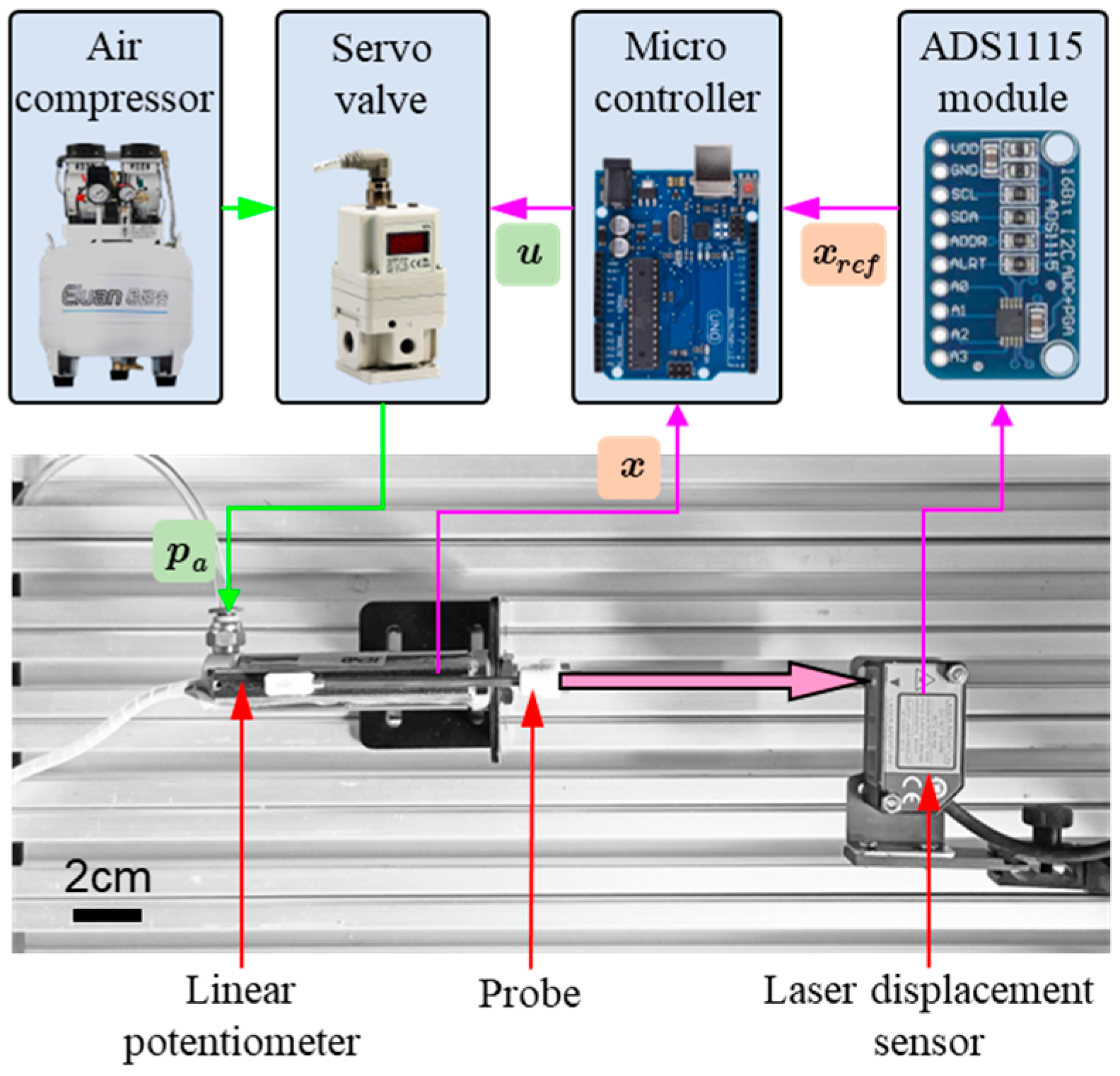
The experimental platform for the calibration of linear potentiometer is displayed in Figure 2. A laser displacement sensor (Sharp Corporation, Osaka, Japan), which has a measurement range, repeatability, and linearity of 160 mm, 0.2 mm, and ±0.2% F.S., respectively, is utilized to measure the displacement of the piston rod.
The calibration process begins with data acquisition. The output of linear potentiometer x and laser displacement sensor x r e f are sampled by the Arduino UNO (Changzhou Kunhang Robot Technology Co., Ltd, Changzhou, China) Analog to Digital Converter (ADC) module and an ADS1115 module, respectively. The ADS1115 module was manufactured by Texas Instruments, Dallas, TX, USA. During the experiments, a varying actuating pressure p a is utilized to control the displacement of the piston rod to produce reciprocating motion within the motion range of the pneumatic cylinder. This data collection process captures both increasing and decreasing motion states to account for potential hysteresis effects. Following data acquisition, the BCM model is formulated based on rational Bezier curves, which introduce weight coefficients to enhance the flexibility and accuracy of the calibration curve. The model parameters, including control points and weights, are optimized using MATLAB R2022B’s fmincon solver to minimize the Euclidean norm of the residual error between the calibrated output and the true value. This optimization ensures that the BCM achieves a smooth and accurate calibration with lower-order models compared to traditional polynomial methods. Finally, the calibrated model is validated against a separate dataset to confirm its effectiveness, demonstrating significant improvements in calibration accuracy and reduced computational cost, making it suitable for real-time applications.
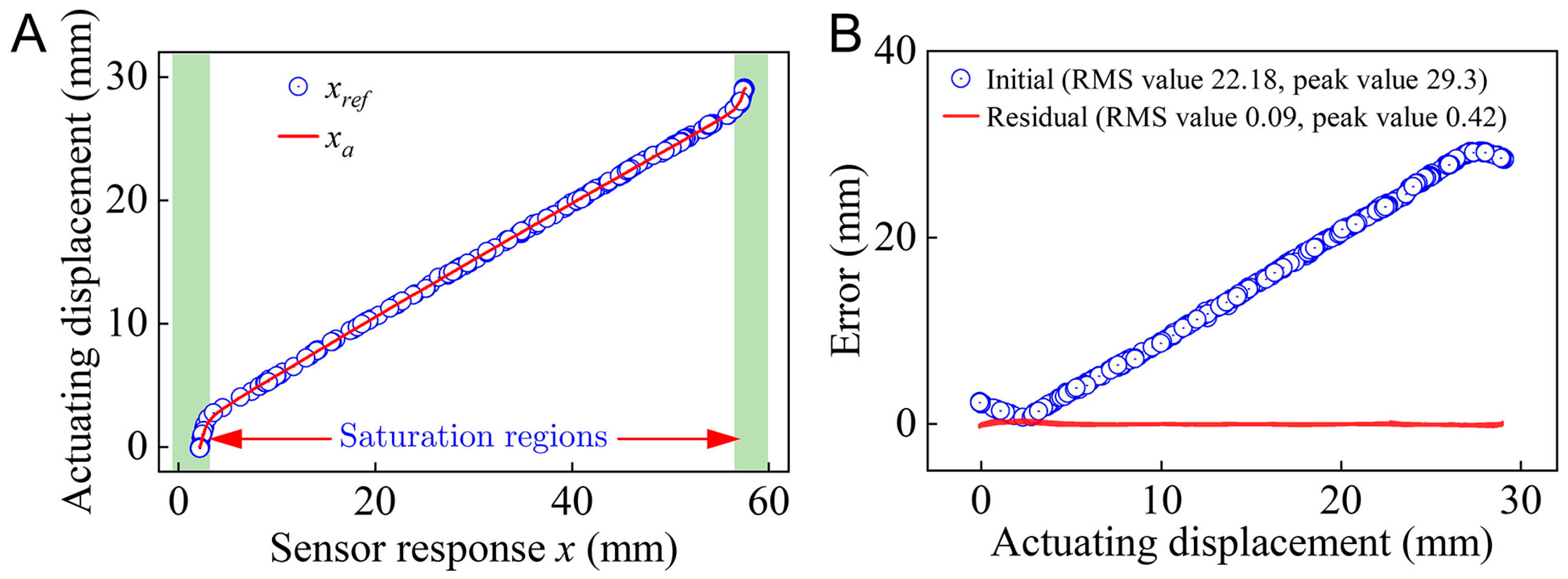
The measured reference value x r e f with respect to x is displayed in Figure 3A. It reveals that due to the inherent nonlinearity, the linear potentiometer exhibits two saturation regions at the two sides of the measurement range. Through the BCM, the calibrated measurement results of linear potentiometer x a are compared with the reference value shown in Figure 3A. The corresponding measurement errors are computed and shown in Figure 3B. The results reveal that through the BCM calibration, the RMS value of the initial measurement error could be reduced to approximately 0.09 mm, with a reduction of approximately 99.6%. This level of error reduction essentially fulfills the requirements for subsequent modeling and control.

2.2. Problem Description

As illustrated in Figure 1A, by neglecting the dynamic effects, the actuating force F a of the piston rod can be modeled as
F a = p a s a F s x a F r x a , x ˙ a , s x a
where p a and s a denote the actuating pressure and piston area, respectively, and F s and F r denote the restoring force of the spring and the friction between the piston and cylinder wall, respectively. For a standard single-acting pneumatic cylinder, its internal spring is generally designed to be in a compressed state to yield preload F s o . Therefore, the restoring force of the spring can be given as
F s x a = k x x a + F s o
where k x denotes the stiffness of the spring. Due to uncontrollable factors in the spring fabrication process, spring stiffness k x will inevitably exhibit nonlinear and hysteresis characteristics under different spring lengths.
For a pneumatic cylinder, the friction between the piston and cylinder wall depends on a variety of factors, such as piston displacement x a , piston speed x ˙ a , humidity [32,33], and so on. For the present single-acting pneumatic system, piston displacement x a , speed x ˙ a , and the motion state are considered as the influencing factors of friction F r , where the motion state s x a of the piston is given by
s x a = u j u j 1
where u denotes the actuating voltage of the servo valve and subscript j denotes the discrete time series. For an ideal servo valve, actual actuating pressure p a can be controlled by input voltage instruction u as
p a = k u u
where k u denotes the constant gain coefficient.
According to Equations (1)–(4), the target actuating voltage instruction for a given actuating force F a can be obtained as
u = F a + F s x a + F r x a , x ˙ a , s x a k u s a = f u F a , x a , x ˙ a , s x a
Similarly, actuating force F a can be predicted by
F a = k u s a u F s x a F r x a , x ˙ a , s x a = f F u , x a , x ˙ a , s x a

3. Neural Network Modeling

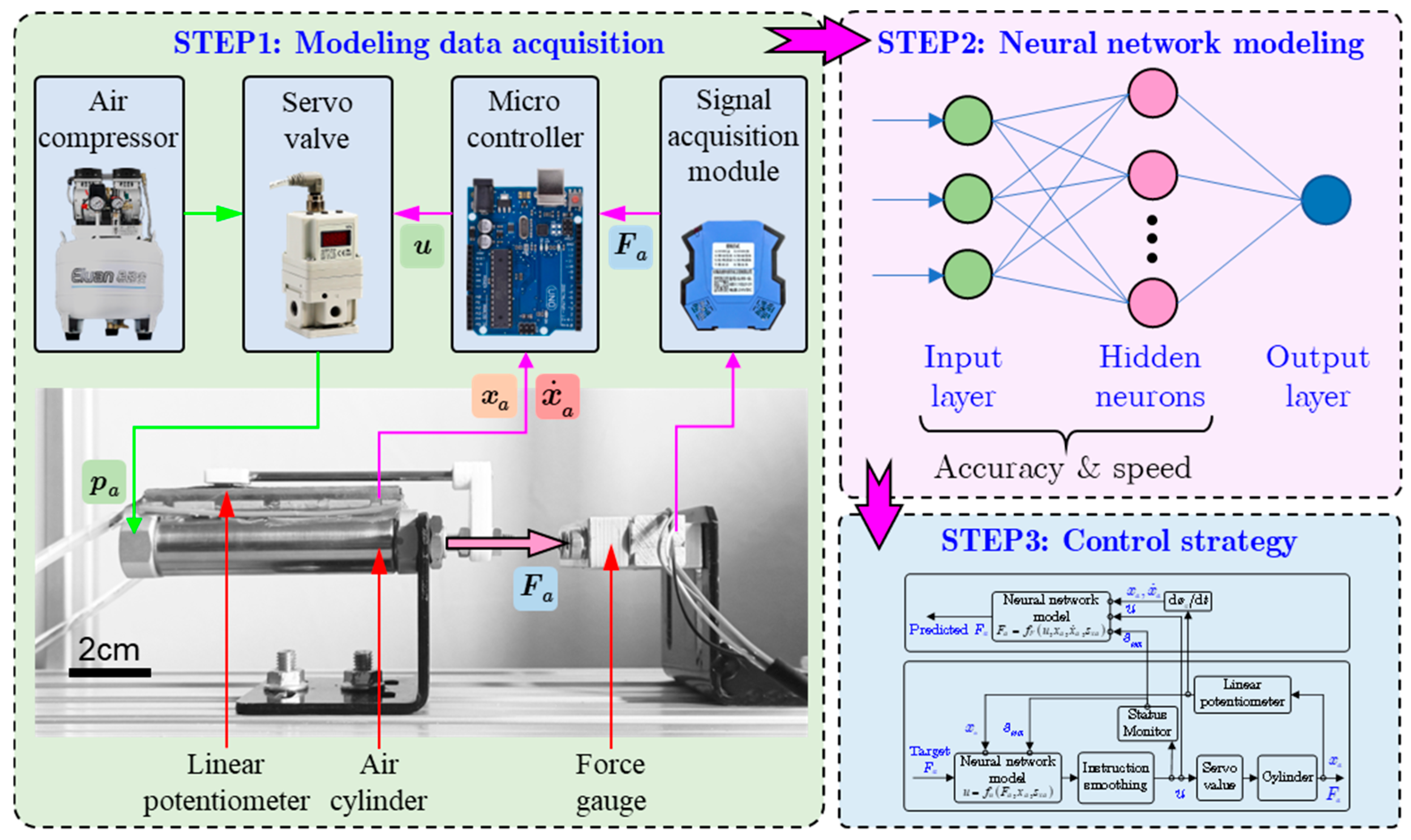
As described above, due to the nonlinear unknown factors, theoretical control modeling is quite difficult in practical control applications. The neural network method is more appropriate for nonlinear and complex modeling problems. The overall modeling procedure for the actuating force of the single-acting pneumatic system is depicted in Figure 4, which is mainly composed of three steps:
(1)
Data acquisition. Sampe the essential data for the input and output layers of the neural network model according to Equations (5) and (6).
(2)
Neural network modeling and analysis. Train and obtain an optimal neural network model based on the data from the input and output layers. Since execution speed is an essential requirement for real-time control, a larger dimension of the input layer and a greater number of hidden neurons could lead to a reduction in the real-time execution speed. Therefore, the effects of different input layer designs and different numbers of hidden neurons on modeling accuracy and execution speed will be quantitatively evaluated to obtain an optimal balance between the modeling accuracy and real-time execution speed.
(3)
Control strategy design. Construct the control strategy for the feedforward actuating force control based on the neural network model.

3.1. Experimental Setup

To acquire the modeling data, an experimental platform for the actuating force control of the single-acting pneumatic system is established and shown in Figure 4. The actuating pressure p a of the pneumatic cylinder is controlled by a servo valve, of which actuating voltage instruction u is given by a Micro Controller Unit (MCU). Actuating displacement x a and velocity x ˙ a are sampled by the internal 10-bit ADC module of the MCU. Piston motion state s x a is computed according to Equation (3). Actuating force F a is measured by a force sensor, which has a measurement range of 100 N, F.S. nonlinearity of 0.1%, repeatability of 0.05%, and hysteresis of 0.05%.

3.2. Data Acquisition

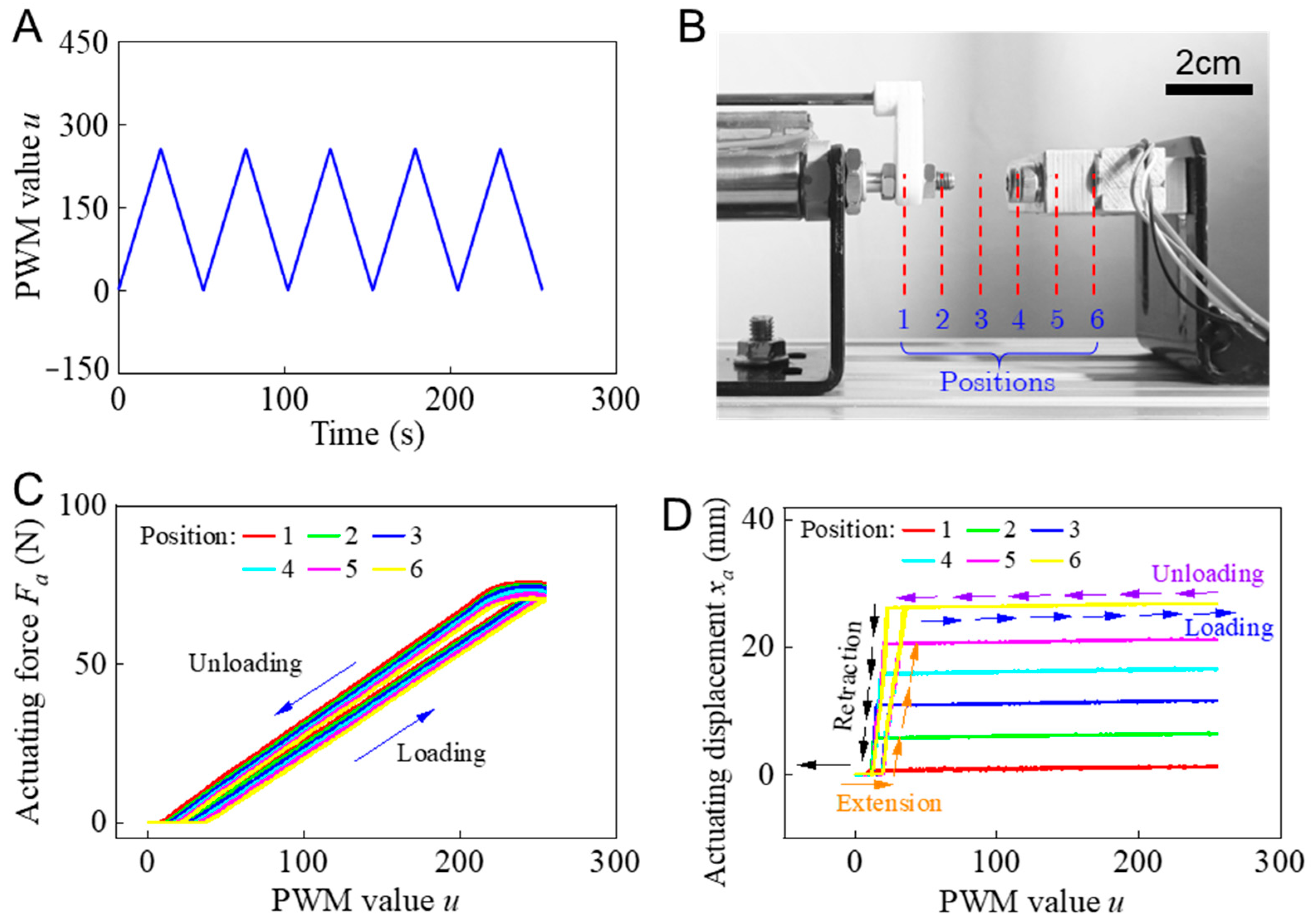
Taking into consideration the hysteresis characteristics of the spring and friction F r , the loading and unloading experiment of the pneumatic cylinder was performed five times by controlling actuating voltage instruction u , as shown in Figure 5A. Taking into consideration the stiffness nonlinearity of the spring, the above experiment was performed under different displacements by adjusting the position of the force sensor, as depicted in Figure 5B. Some typical results, such as actuating force and displacement with respect to different actuating voltage instruction u are shown in Figure 5C and Figure 5D, respectively. Figure 5C reveals that the actuating force exhibits a hysteresis loop during the loading and unloading process. As the actuating displacement varies, the hysteresis loop shifts accordingly.

3.3. Neural Network Structure Analysis

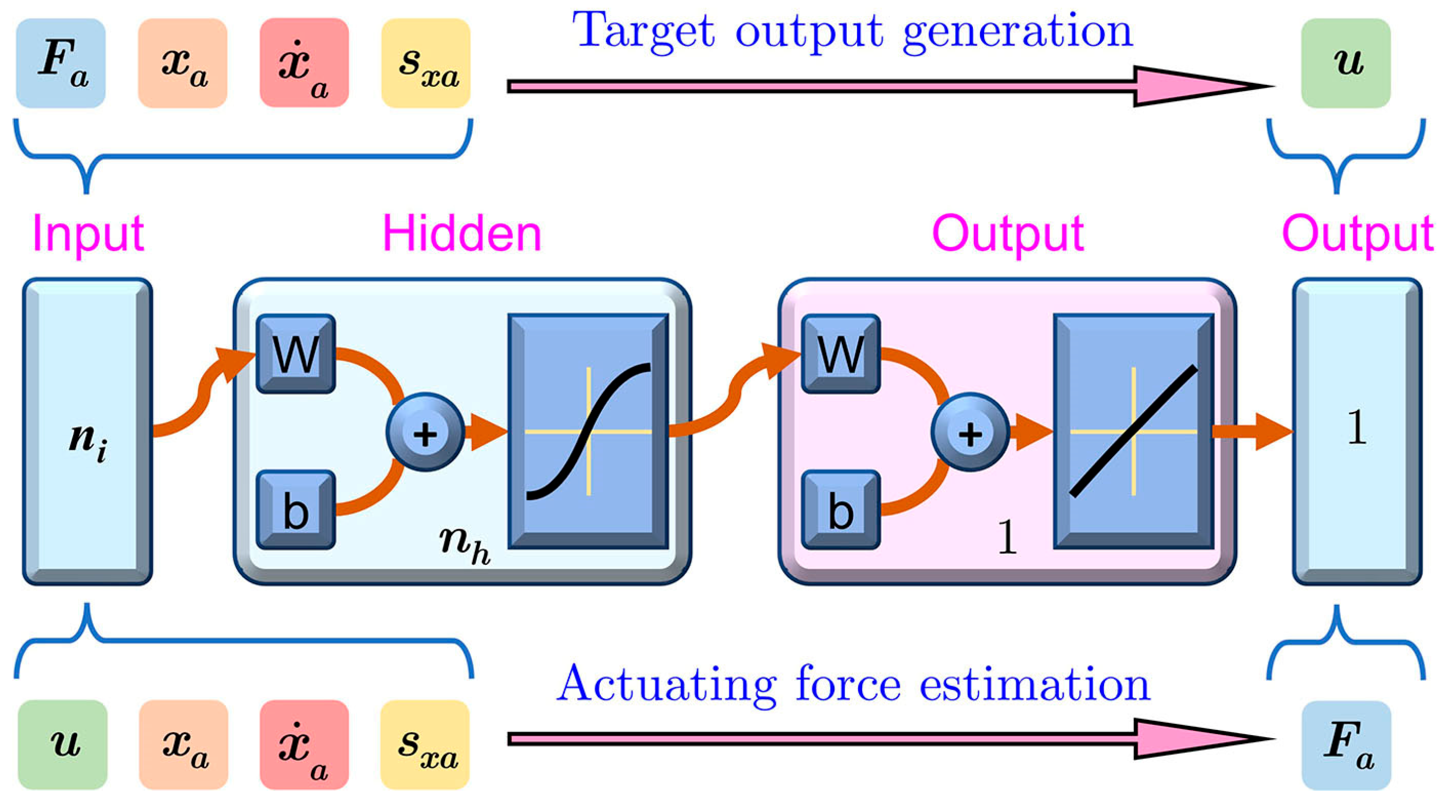
According to Equations (5) and (6), the structure of the neural network model is designed, as shown in Figure 6. The neural network model consists of an input layer, one or more hidden layers, and an output layer. The input layer includes variables such as actuating pressure, piston displacement, piston velocity, and motion state, which have been identified through our analysis as critical factors influencing the actuating force. The hidden layers employ neurons with Rectified Linear Unit (ReLU) activation functions to capture the nonlinear relationships within the system, while the output layer utilizes a linear activation function [36]. For the present neural network model, its computing speed depends on the dimension of the input layer and the number of the hidden neurons. To optimize the real-time execution speed of the neural network model, its input and hidden layers are analyzed to determine their ideal dimension.
(1)
Input layer design
A quantitative analysis of the modeling accuracy is performed to reveal the modeling effectiveness of the variables in the input layer by evaluating the good-fit parameters of the trained neural network models.
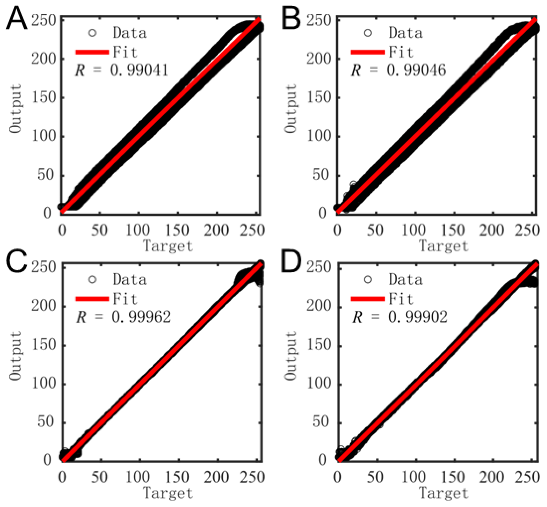
In modeling target voltage instruction u , four kinds of input layers are designed: F a , x a , F a , x a , x ˙ a , F a , x a , s x a , and F a , x a , x ˙ a , s x a . The corresponding trained results and good-fit parameters R 0 , 1 are shown in Figure 7. Generally, a higher value of R denotes a higher modeling accuracy. The results reveal that input layer F a , x a , s x a has the best modeling accuracy, for which the good-fit parameters can achieve a maximum of about 0.99962.
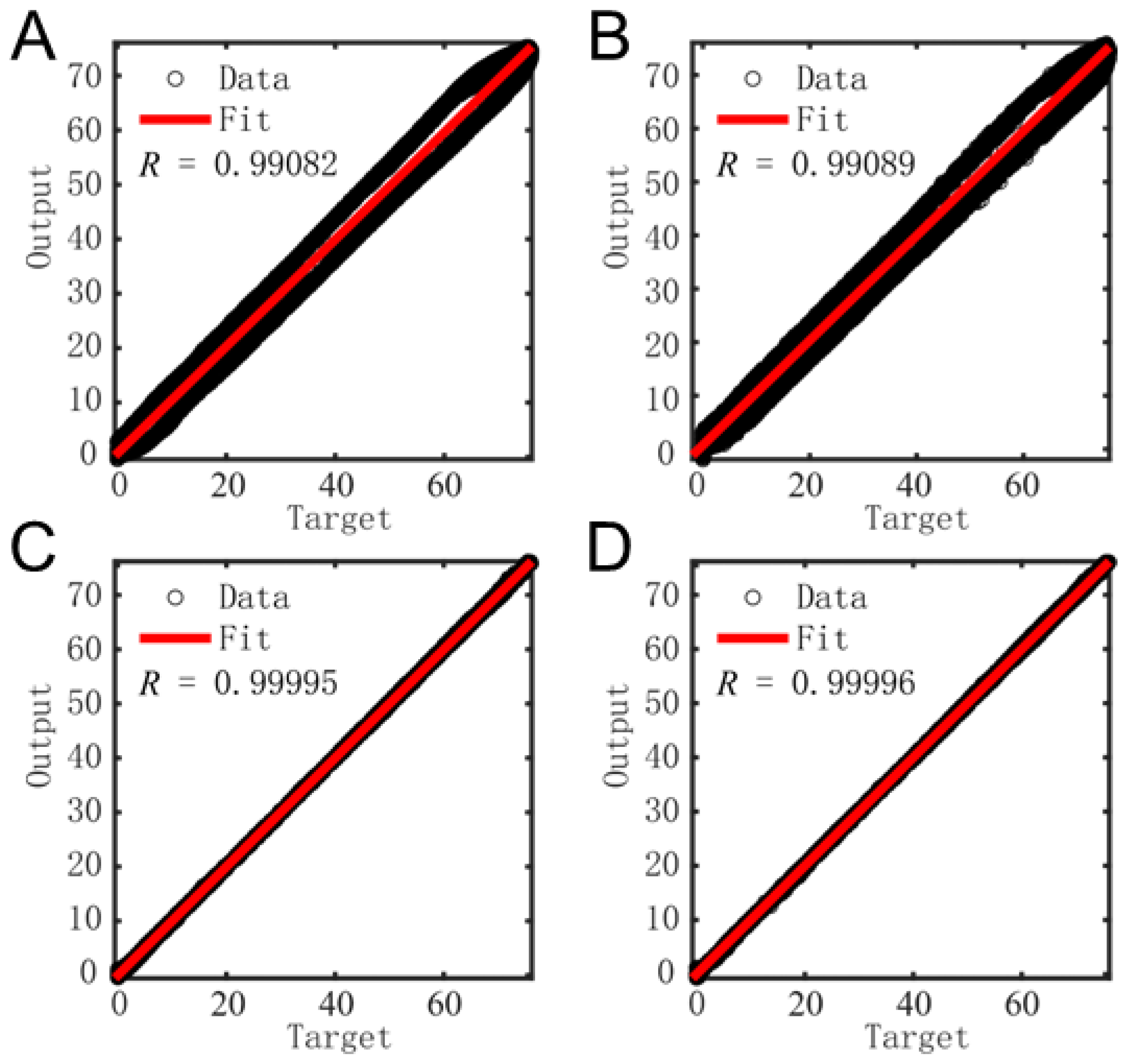
Four kinds of input layers are designed for the self-sensing modeling of the actuating force F a : u , x a , u , x a , x ˙ a , u , x a , s x a , and u , x a , x ˙ a , s x a . The corresponding results of good-fit parameters R are shown in Figure 8. These reveal that u , x a , x ˙ a , and s x a have an influence on the modeling accuracy of F a . Therefore, the input layer for the neural network model of F a is designed as u , x a , x ˙ a , s x a to achieve the best modeling accuracy.
(2)
Computing cost
Generally, a higher dimension of the hidden layer can improve the modeling accuracy but also increase the real-time computing cost. Therefore, a balance between the computing cost and modeling accuracy is required. According to the designed input layer of the neural network model, the modeling accuracy and real-time computing speed are evaluated under different numbers of hidden neurons. The modeling accuracy of u and F a are characterized by the Root-Mean-Square (RMS) value of E u and E f , respectively.
E u = u neural network model u experimental data E f = F a , neural network model F a , experimental data
The neural network model under different numbers of hidden neurons is compiled into C code and executed on an Arduino UNO MCU to evaluate their average computing cost over 1000 runs. The RMS value and computing cost of the neural network models of u and F a under different numbers of hidden neurons are shown in Figure 9A and Figure 9B, respectively.
Figure 9 reveals that the modeling accuracy of u and F a reaches their limit levels when the number of the hidden neurons increases to 5 and 7, respectively. The computing cost increases almost linearly with respect to the increment in the number of hidden neurons. Taking into consideration the balance between computing cost and modeling accuracy, the number of hidden neurons for the neural network models of u and F a is determined to be 5 and 7, respectively. These configurations can be executed on a microcontroller within 2 ms, thereby fulfilling the real-time requirement for actuating force control.

3.4. Feedforward Control Strategy

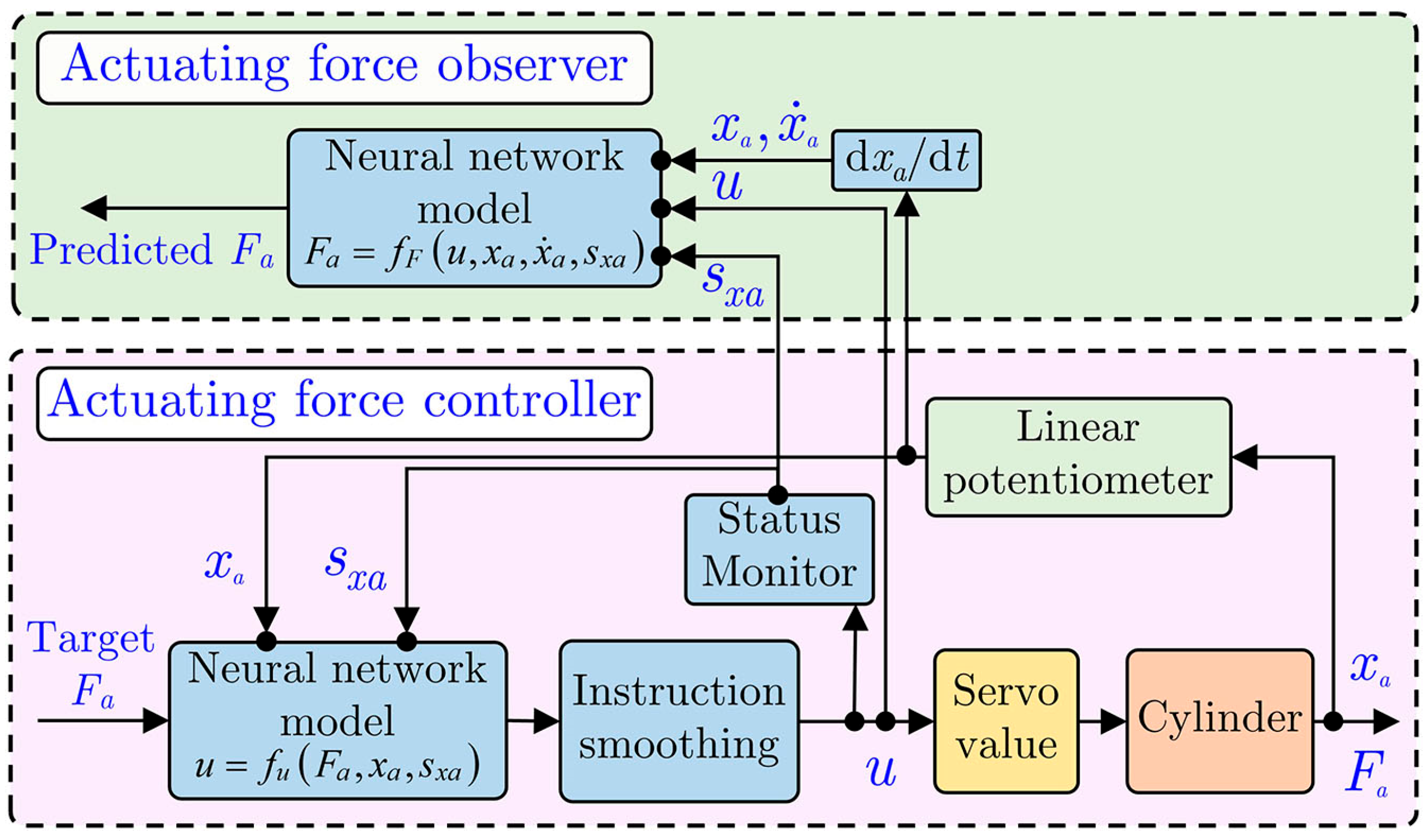
The control strategy of the single-acting pneumatic system is shown in Figure 10. The control system is mainly composed of two modules: the actuating force controller and the actuating force observer. In the actuating force controller, the neural network model of u is utilized to predict the target actuating voltage instruction for the servo valve to actuate the pneumatic cylinder in a feedforward approach. During the control process, the actuating force of the pneumatic cylinder can be perceived by the actuating force observer in a sensorless manner.

4. Experimental Results and Discussion

To verify the effectiveness of the established neural network models, actuating force tracking control and step force control experiments are performed based on the experimental platform shown in Figure 4.

4.1. Actuating Force Tracking Control

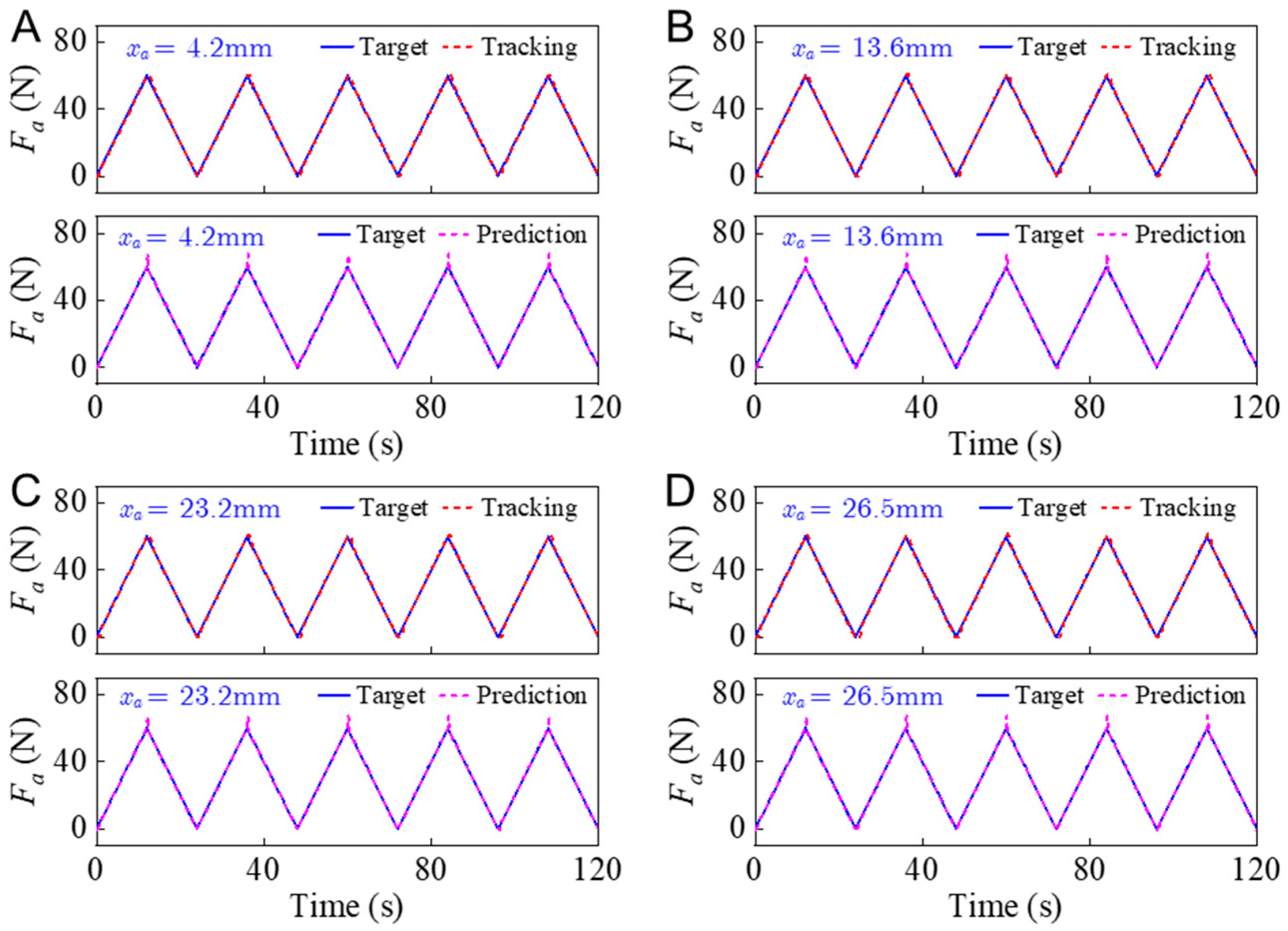
In the actuating force tracking control experiments, the target actuating force is set to range from 0 to 60 N, with a step of 1 N. As shown in Figure 5B, the modeling data are sampled at the positions of 1.3 mm, 6.5 mm, 11.6 mm, 16.6 mm, 21.3 mm, and 26.9 mm. To make a better verification, the actuating force tracking control experiments are performed at the positions of 4.2 mm, 13.6 mm, 23.2 mm, and 26.5mm, respectively, which are staggered with respect to the modeling positions. The corresponding actuating force tracking and prediction results for the above four positions are shown in Figure 11.
Figure 11 reveals that the tracking and prediction results of the actuating force coincide well with the target value overall. This indicates that the developed neural network models of u and F a are valid.
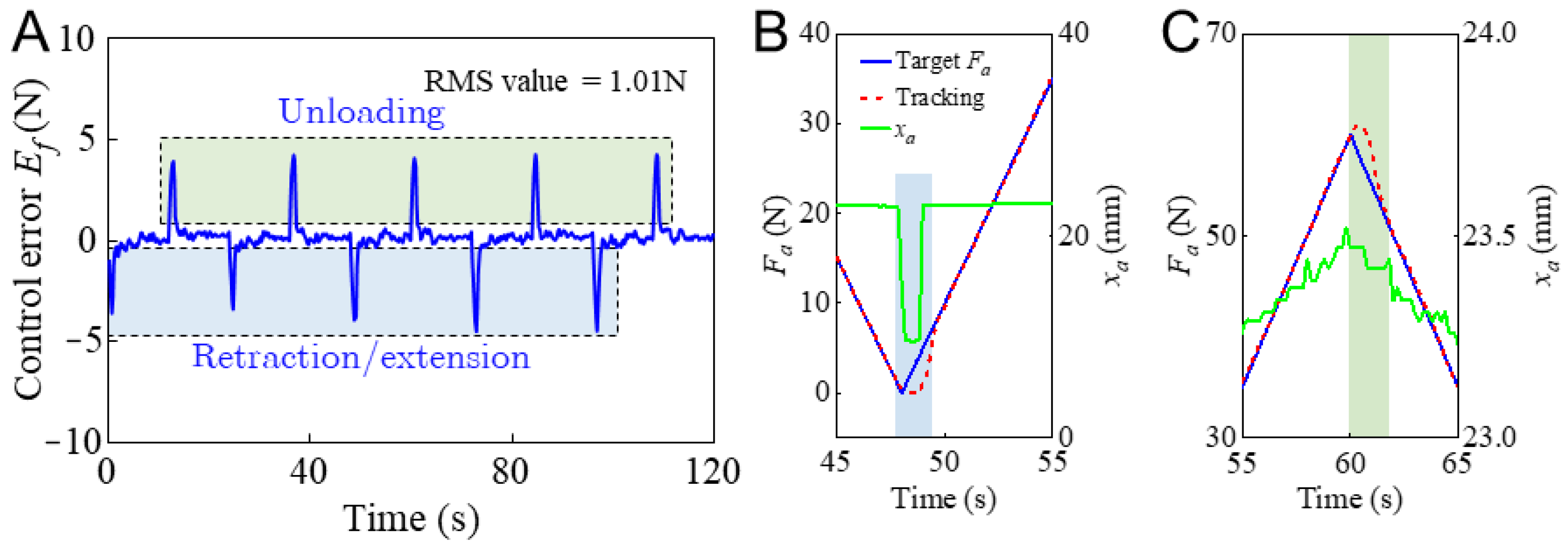
A typical control error of the actuating force at x a = 23.2 mm is computed and displayed in Figure 12A. It reveals that the peak value of the control error is dominated by two transient waves in each control period which occur at the moment of unloading-to-loading switching or loading-to-unloading switching. In these two processes, the amplitude of the control error has a peak value of about 5 N. During the loading or unloading process, the amplitude of the control error is less than 0.5 N. The RMS value of the control error is about 1 N.
Some enlarged views of F a and x a are displayed in Figure 12B and Figure 12C, respectively, to illustrate the mechanism of the control error. The response of x a in Figure 12B reveals that the piston rod produces retraction and extension motions during the unloading-to-loading switching process. In this process, the piston rod has no contact with the force sensor, and the actuating force is disturbed by the dynamic inertia force of the piston rod, which has not been modeled in the present study to compensate for the actuating force control model. As the piston rod contacts with the force sensor, its velocity decreases dramatically. During the loading process, the piston rod moves in a quasi-static manner, and the dynamic inertia force of the piston rod disappears. As a result, the measured actuating force coincides well with the target force in the loading process.
In the loading-to-unloading switching process, the actuating force control also exhibits a hysteresis characteristic. The actuating displacement of the piston rod reveals that the hysteresis process lasts about 0.1 mm. The transient hysteresis characteristic of the actuating force control in the loading-to-unloading switching process can be attributed to the micro-deformation of the elastic sealing ring, which is installed on the piston and contacts the cylinder wall. The friction between the sealing ring and cylinder wall varies gradually as the motion state of the piston changes. In the steady-state of the unloading process, the actuating force control achieves an ideal tracking performance.

4.2. Step Force Control

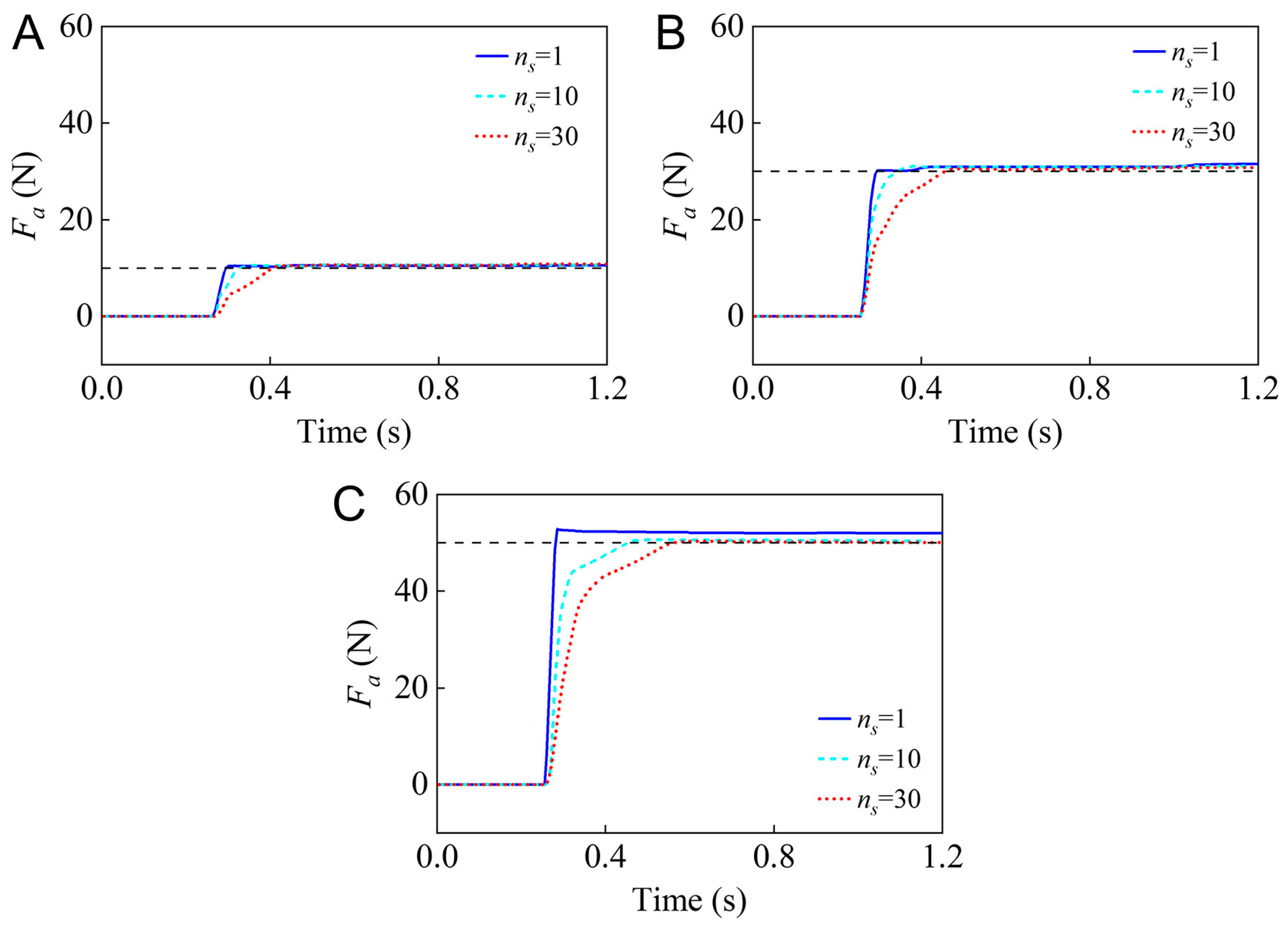
Step force control experiments are performed to further evaluate the effectiveness of the established neural network model and the control strategy. Some typical step force control responses, for which the target values are set at 10 N, 30 N, and 50 N, respectively, are shown in Figure 13.
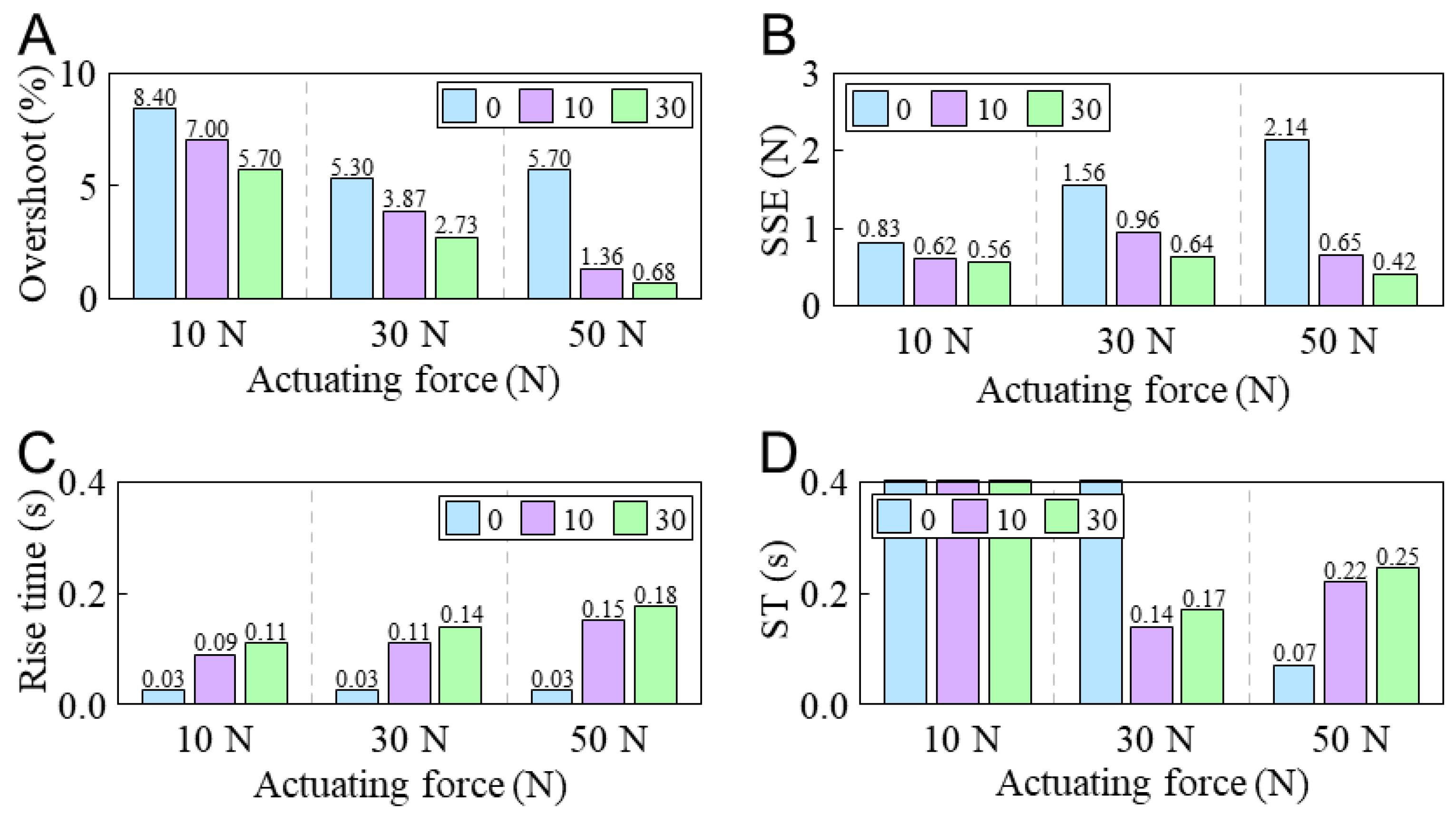
The results reveal that the feedforward actuating force control has a rapid response speed. The rise time for the different target forces is about 0.03 s. However, as the target actuating force increases, the Steady-State Error (SSE) also increases accordingly. In the present study, the SSE for the target actuating forces of 10 N, 30 N, and 50 Nis are about 0.56 N, 1.56 N, and 2.14 N, respectively. This indicates that the amplitude of the target actuating force can exacerbate the steady-state error of the step force control.
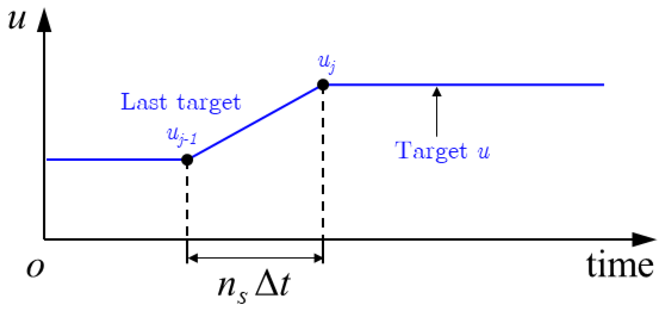
To improve the step force control accuracy of the single-acting pneumatic system, an instruction smoothing module is designed to smooth target actuating voltage instruction u , which is generated by the neural network model, as depicted in Figure 10. The time series of the actuating voltage instruction, which is generated by the instruction smoothing module, is given as
u j = u j 1 + i u u j 1 n s , i 1 , n s
where u , u j , and u j 1 denote the target, current, and last actuating voltage instructions of the servo valve, respectively, n s denotes the number of steps of the smoothing operation, and i 1 , n s denotes the time counter. A graphical illustration of Equation (8) is illustrated in Figure 14. Once target u is updated by the neural network model, the actuating voltage instruction will be applied to the servo valve linearly. The total instruction smoothing time will last for n s Δ t , where Δ t denotes the sampling time of the controller. In the present study, Δ t is set to 10 ms. In the step force control experiments, n s is set to 1, 10, and 30, respectively, to observe the control response of the actuating force. The obtained step responses are compared in Figure 13. The corresponding control overshoot, rise time, Settling Time (ST), and SSE of the step force control response are summarized in Figure 15.
Figure 15A,B reveals that increasing the steps of the smoothing operation n s reduces the percent overshoot and steady-state error of the step force control. The improvement is especially obvious in larger actuating force control. For F a = 50 N, the percent overshoot and SSE can achieve reductions of about 88.1% and 80.3%, respectively, as n s increases from 1 to 30. The main reason for this phenomenon is that the pressure control system of the servo valve has a constant structure. A large variation in the actuating voltage instruction can exacerbate the overshoot and steady-state error of the actuating pressure and, subsequently, the actuating force of the single-acting pneumatic cylinder. A smoother actuating voltage instruction can improve the overshoot and steady-state error characteristics of the pressure control system of the servo valve.
Figure 15C,D reveals that as n s increases, the rise time and settling time also increase accordingly. For F a = 50 N, the settling time will increase from 0.07 s to about 0.25 s as n s increases from 1 to 30.
It can be observed that pneumatic cylinders offer rapid and precise force control, making them suitable for tasks requiring high-speed and accurate actuation. However, other pressure-driven actuators, such as soft actuators and hydraulic actuators, have unique advantages and limitations. Soft actuators provide flexibility and adaptability [37,38] but lack precision [39], whereas hydraulic actuators offer high force capabilities at the cost of increased complexity and maintenance [40,41]. Future research may focus on developing hybrid actuation systems that leverage the strengths of multiple technologies to address the limitations of individual actuators and enhance overall performance across a broader range of applications.

5. Conclusions

This paper presents the neural network modeling and feedforward force control of a single-acting pneumatic cylinder with a nonlinear hysteresis characteristic. A single-acting pneumatic system is fabricated to experimentally verify the effectiveness of the proposed modeling and control method. Experimental results reveal that:
(1)
The established neural network models of the actuating force can be executed on a microcontroller within 2 ms, thereby fulfilling the real-time requirement in actuating force control.
(2)
The actuating force can achieve ideal tracking of the target via a feedforward approach. In the loading and unloading processes, the amplitude of the control error is less than 0.5 N. The overall RMS value of the control error is about 1 N.
(3)
In step force control, a larger step variation of the target can lead to an increase in the steady-state error and affect the control accuracy. An instruction smoothing operation can reduce the percent overshoot and steady-state error of the feedforward step actuating force control.

Author Contributions

Conceptualization, H.H.; Methodology, all authors.; Software, X.W.; Validation, S.F. and Y.Z.; Investigation H.H. and Z.L.; Data curation, Y.Y.; Writing—original draft preparation, X.W.; Writing—review and editing, H.H. and Z.L.; Funding acquisition, H.H. All authors have read and agreed to the published version of the manuscript.

Funding

This research is funded by the National Natural Science Foundation of China under Grant Nos. 52305008, Major Project of Basic Science Research in Jiangsu Province No. 24KJA460001, Changzhou Sci&Tech Program under Grant No. CJ20230038 and Qinglan Project of Jiangsu Province of China under Grant No. 31120224005.

Data Availability Statement

Data is contained within the article.

Conflicts of Interest

The authors declare no conflicts of interest.

References

  1. Dong, J.; Shi, J.; Liu, C.; Yu, T. Research of Pneumatic Polishing Force Control System Based on High Speed On/off with PWM Controlling. Robot. Comput. Integr. Manuf. 2021, 70, 102133. [Google Scholar]
  2. Li, J.; Guan, Y.; Chen, H.; Wang, B.; Zhang, T.; Liu, X.; Hong, J.; Wang, D.; Zhang, H. A High-Bandwidth End-Effector with Active Force Control for Robotic Polishing. IEEE Access 2020, 8, 169122–169135. [Google Scholar] [CrossRef]
  3. Fan, C.; Hong, G.S.; Zhao, J.; Zhang, L.; Zhao, J.; Sun, L. The integral sliding mode control of a pneumatic force servo for the polishing process. Precis. Eng. 2019, 55, 154–170. [Google Scholar] [CrossRef]
  4. Kakogawa, A.; Kaizu, Y.; Ma, S. Sensor-Less and Control-Less Underactuated Grippers with Pull-In Mechanisms for Grasping Various Objects. Front. Robot. AI 2021, 8, 631242. [Google Scholar]
  5. Zhang, B.; Xie, Y.; Zhou, J.; Wang, K.; Zhang, Z. State-of-the-art robotic grippers, grasping and control strategies, as well as their applications in agricultural robots: A review. Comput. Electron. Agric. 2020, 177, 105694. [Google Scholar]
  6. Zhong, G.; Hou, Y.; Dou, W. A soft pneumatic dexterous gripper with convertible grasping modes. IJMS 2019, 153–154, 445–456. [Google Scholar]
  7. Yanqiong, F.; Jiangbei, W.; Wu, P. A Novel Fabric-Based Versatile and Stiffness-Tunable Soft Gripper Integrating Soft Pneumatic Fingers and Wrist. Soft Robot. 2019, 6, 1–20. [Google Scholar]
  8. Tanaka, K.; Nishikawa, S.; Niiyama, R. Kuniyoshi, Immediate generation of jump-and-hit motions by a pneumatic humanoid robot using a lookup table of learned dynamics. IEEE Robot. Autom. Lett. 2021, 6, 5557–5564. [Google Scholar]
  9. Ren, H.-P.; Jiao, S.-S.; Li, J.; Deng, Y. Adaptive neural network control of pneumatic servo system considering state constraints. Mech. Syst. Signal Process. 2022, 162, 107979. [Google Scholar]
  10. Li, X.; Yu, H.; Feng, H.; Zhang, S.; Fu, Y. Design and control for WLR-3P: A hydraulic wheel-legged robot. Cyborg Bionic Syst. 2023, 4, 0025. [Google Scholar]
  11. Wang, B.; Wang, Z.; Song, Y.; Zong, W.; Zhang, L.; Ji, K.; Manoonpong, P.; Dai, Z. A neural coordination strategy for attachment and detachment of a climbing robot inspired by gecko locomotion. Cyborg Bionic Syst. 2023, 4, 0008. [Google Scholar]
  12. Jiménez, M.; Kurmyshev, E.; Castaneda, C. Experimental study of double-acting pneumatic cylinder. Exp. Tech. 2020, 44, 355–367. [Google Scholar]
  13. Cheng, P.; Jia, J.; Ye, Y.; Wu, C. Modeling of a Soft-Rigid Gripper Actuated by a Linear-Extension Soft Pneumatic Actuator. Sensors 2021, 21, 493. [Google Scholar] [CrossRef] [PubMed]
  14. Azman, M.A.; Elnimair, M.O.; Hikmat, O.F.; Osman, K.; Kai, C.C. P-adaptive neuro-fuzzy and PD-fuzzy controller design for position control of a modified single acting pneumatic cylinder. In Proceedings of the 2013 IEEE/ASME International Conference on Advanced Intelligent Mechatronics, Wollongong, NSW, Australia, 9–12 July 2013; pp. 176–181. [Google Scholar]
  15. Hua, H.; Liao, Z.; Wu, X.; Chen, Y.; Feng, C. A Back-drivable Linear Force Actuator for Adaptive Grasping. J. Mech. Sci. Technol. 2022, 36, 4213–4220. [Google Scholar]
  16. Hua, H.; Song, J.; Zhao, J.; Liao, Z. Sensor-less Grasping Force Control of a Pneumatic Underactuated Robotic Gripper. J. Mech. Robot. 2024, 16, 031005. [Google Scholar]
  17. Hamon, P.; Michel, L.; Plestan, F.; Chablat, D. Model-free based control of a gripper actuated by pneumatic muscles. Mechatronics 2023, 95, 103053. [Google Scholar]
  18. Chen, F.; Zhao, H.; Li, D.; Chen, L.; Tan, C.; Ding, H. Contact force control and vibration suppression in robotic polishing with a smart end effector. Robot. Comput. Integr. Manuf. 2019, 57, 391–403. [Google Scholar]
  19. Pei, G.; Yu, M.; Xu, Y.; Ma, C.; Lai, H.; Chen, F.; Lin, H. An Improved PID Controller for the Compliant Constant-Force Actuator Based on BP Neural Network and Smith Predictor. Appl. Sci. 2021, 11, 2685. [Google Scholar] [CrossRef]
  20. Mazare, M.; Taghizadeh, M.; Kazemi, M.G. Optimal hybrid scheme of dynamic neural network and PID controller based on harmony search algorithm to control a PWM-driven pneumatic actuator position. J. Vib. Control 2018, 24, 3538–3554. [Google Scholar]
  21. Jiang, X.; Wang, Z.; Zhang, C.; Yang, L. Fuzzy neural network control of the rehabilitation robotic arm driven by pneumatic muscles. Ind. Robot. Int. J. 2015, 42, 36–43. [Google Scholar]
  22. Chavoshian, M.; Taghizadeh, M.; Mazare, M. Hybrid dynamic neural network and PID control of pneumatic artificial muscle using the PSO algorithm. Int. J. Autom. Comput. 2020, 17, 428–438. [Google Scholar] [CrossRef]
  23. Zhao, L.; Zhang, B.; Yang, H.; Wang, Y. Observer-based integral sliding mode tracking control for a pneumatic cylinder with varying loads. IEEE Trans. Syst. Man Cybern. Syst. 2018, 50, 2650–2658. [Google Scholar] [CrossRef]
  24. Krause, J.; Bhounsule, P. A 3D printed linear pneumatic actuator for position, force and impedance control. Actuators 2018, 7, 24. [Google Scholar] [CrossRef]
  25. Zhao, L.; Yang, Y.; Xia, Y.; Liu, Z. Active disturbance rejection position control for a magnetic rodless pneumatic cylinder. ITIE 2015, 62, 5838–5846. [Google Scholar] [CrossRef]
  26. Taheri, B.; Case, D.; Richer, E. Force and stiffness backstepping-sliding mode controller for pneumatic cylinders. IEEE/ASME Trans. Mechatron. 2014, 19, 1799–1809. [Google Scholar]
  27. Hua, H.; Liao, Z.; Wu, X.; Chen, Y. A Bezier based state calibrating method for low-cost potentiometer with inherent nonlinearity. Measurement 2021, 178, 109325. [Google Scholar] [CrossRef]
  28. Hua, H.; Wu, X.; Shi, N.; Zhang, J.; Zhao, C.; Zhu, Z. Design and evaluation of a novel dual-channel complementary potentiometer for rotation measurement. Measurement 2024, 230, 114548. [Google Scholar]
  29. Hua, H.; Liao, Z.; Song, J.; Liu, Y. A Sparse Piecewise Calibration Method for Potentiometer with Inherent Nonlinearity: A Comparison Study. Measurement 2022, 204, 112033. [Google Scholar] [CrossRef]
  30. Chen, Y.; Tao, G.; Liu, H. High Precision Adaptive Robust Neural Network Control of a Servo Pneumatic System. Appl. Sci. 2019, 9, 3472. [Google Scholar] [CrossRef]
  31. Li, Y.; Cao, Y.; Jia, F. A Neural Network Based Dynamic Control Method for Soft Pneumatic Actuator with Symmetrical Chambers. Actuators 2021, 10, 112. [Google Scholar] [CrossRef]
  32. Pham, V.-H.; Nguyen, T.-D.; Bui, T.-A. Behavior of Friction in Pneumatic Cylinders with Different Relative Humidity. Tribol. Ind. 2020, 42, 400. [Google Scholar] [CrossRef]
  33. Nguyen, T.-D.; Pham, V.-H. Study of the effects of relative humidity and velocity on the friction characteristics of pneumatic cylinders. Int. J. Mod. Phys. B 2020, 34, 2040139. [Google Scholar] [CrossRef]
  34. Hua, H.; Zhang, J.; Zhao, C.; Wu, Z.; Song, J.; Liao, Z. Prediction-Based Rapid Force Control of a Single-Acting Pneumatic Cylinder Under Hysteresis Nonlinearity. ISA Trans. 2025, 158, 686–696. [Google Scholar] [CrossRef] [PubMed]
  35. Turkseven, M.; Ueda, J. Model-based force control of pneumatic actuators with long transmission lines. IEEE/ASME Trans. Mechatron. 2018, 23, 1292–1302. [Google Scholar] [CrossRef]
  36. Banerjee, C.; Mukherjee, T.; Pasiliao, E., Jr. An empirical study on generalizations of the ReLU activation function. In Proceedings of the 2019 ACM Southeast Conference, Kennesaw, GA, USA, 18 April 2019; pp. 164–167. [Google Scholar]
  37. Gunawardane, P.D.S.H.; Cheung, P.; Zhou, H.; Alici, G.; de Silva, C.W.; Chiao, M. A versatile 3d-printable soft pneumatic actuator design for multi-functional applications in soft robotics. Soft Robot. 2024, 11, 709–723. [Google Scholar] [CrossRef]
  38. Le, X.T.; Gunawardane, P.H.; Mallikarachchi, S.; Chiao, M.; Godage, I.S. Hybrid Control of 3D-Printed Multimodal Soft Pneumatic Actuators. In Proceedings of the 2024 IEEE International Conference on Mechatronics and Automation (ICMA), Tianjin, China, 4–7 August 2024; pp. 1753–1758. [Google Scholar]
  39. Yongkang, J.; Diansheng, C.; Che, L.; Jian, L. Chain-Like Granular Jamming: A Novel Stiffness-Programmable Mechanism for Soft Robotics. Soft Robot. 2019, 6, 118–132. [Google Scholar]
  40. Lubecki, M.; Stosiak, M.; Skačkauskas, P.; Karpenko, M.; Deptuła, A.; Urbanowicz, K. Development of composite hydraulic actuators: A review. Actuators 2022, 11, 365. [Google Scholar] [CrossRef]
  41. Yao, Z.; Xu, F.; Jiang, G.-P.; Yao, J. Data-driven control of hydraulic manipulators by reinforcement learning. IEEE/ASME Trans. Mechatron. 2023, 29, 2673–2684. [Google Scholar] [CrossRef]
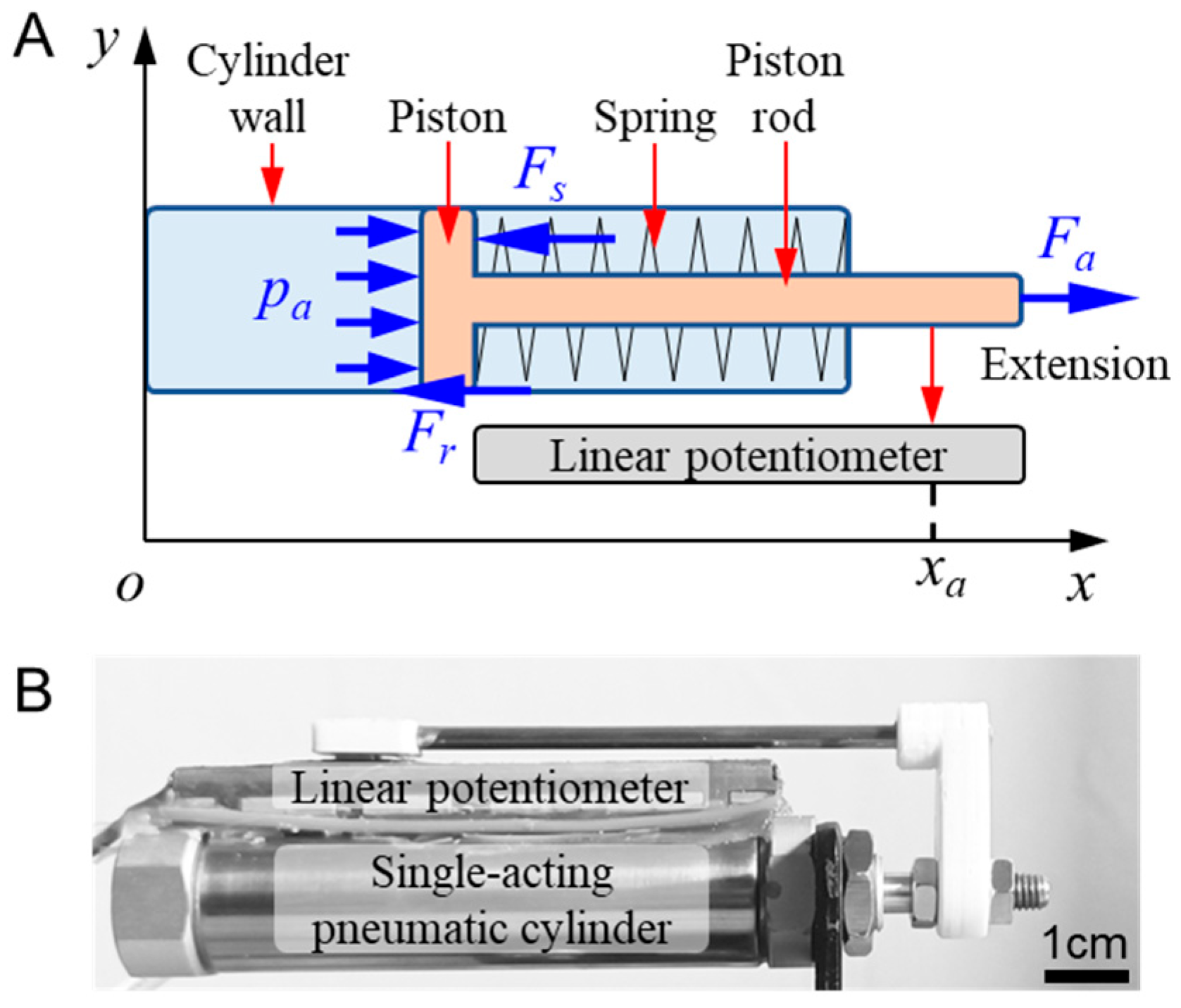
Figure 1. Hardware description (A) and fabricated prototype (B) of a single-acting pneumatic cylinder.
Actuators 14 00162 g001
Figure 2. Experimental platform for inherent nonlinearity calibration of the linear potentiometer.
Actuators 14 00162 g002
Figure 3. Inherent nonlinearity calibration results: (A) Comparison of calibrated results and real value; (B) Comparison of initial measurement error and residual measurement error of the linear potentiometer.
Actuators 14 00162 g003
Figure 4. Procedure of the neural network modeling.
Actuators 14 00162 g004
Figure 5. Data acquisition for neural network modeling: (A) Actuating voltage instruction for loading and unloading control; (B) Experiment positions; (C,D) Actuating force and position response with respect to actuating voltage instruction under different positions, respectively.
Actuators 14 00162 g005
Figure 6. Neural network structure.
Actuators 14 00162 g006
Figure 7. Modeling accuracy of the target voltage instruction under different input layer designs. The horizontal and vertical coordinates represent the input and output values, respectively, of the target voltage instruction modeling data. The black line denotes the actual data distribution, and the red line represents the fit to the data. (A) Input layer F a , x a ; (B) Input layer F a , x a , x ˙ a ; (C) Input layer F a , x a , s x a ; (D) Input layer F a , x a , x ˙ a , s x a .
Actuators 14 00162 g007
Figure 8. Modeling accuracy of the self-sensing model of the actuating force under different input layers. The horizontal and vertical coordinates represent the input and output values, respectively, of the target voltage instruction modeling data. The black line denotes the actual data distribution, and the red line represents the fit to the data. (A) Input layer u , x a ; (B) Input layer u , x a , x ˙ a ; (C) Input layer u , x a , s x a ; (D) Input layer u , x a , x ˙ a , s x a .
Actuators 14 00162 g008
Figure 9. Modeling accuracy and computing cost of the neural network models of u (A) and F a (B) under different numbers of hidden neurons. The blue line and circles represent the RMS values of Eu and Ef, respectively, as a function of the number of neurons. The red line and squares indicate the corresponding computing cost in milliseconds. This color-coded representation helps distinguish between the RMS values and computing costs across different neuron counts.
Actuators 14 00162 g009
Figure 10. Control strategy of the single-acting pneumatic system.
Actuators 14 00162 g010
Figure 11. Actuating force tracking and prediction results: (AD) x a = 4.2 mm, 13.6 mm, 23.2 mm, and 26.5, respectively.
Actuators 14 00162 g011
Figure 12. Actuating force tracking error (A) and enlarged view of a typical unloading-to-loading switching (B) and loading-to-unloading switching (C) process at x a = 23.2 mm.
Actuators 14 00162 g012
Figure 13. Step response of the actuating force control under different target values: (A) F a = 10 N, (B) F a = 30 N, (C) F a = 50 N.
Actuators 14 00162 g013
Figure 14. Instruction smoothing of the actuating voltage of the servo valve. The blue solid line shows the process of adjusting actuating voltage u from previous target value uj−1 to new target value uj over time span nsΔt. The black dotted lines mark the start and end points of this adjusting process.
Actuators 14 00162 g014
Figure 15. Step force control performance under different n s : (A) Percent overshoot, (B) Steady-state error, (C) Rise time and (D) Settling time.
Actuators 14 00162 g015
Disclaimer/Publisher’s Note: The statements, opinions and data contained in all publications are solely those of the individual author(s) and contributor(s) and not of MDPI and/or the editor(s). MDPI and/or the editor(s) disclaim responsibility for any injury to people or property resulting from any ideas, methods, instructions or products referred to in the content.