Article

Photo-Responsive Liquid Crystal Elastomer Coils Inspired by Tropism Movements of Plants

1
National Key Laboratory of Science and Technology on Advanced Composites in Special Environments, Harbin Institute of Technology, Harbin 150080, China
2
Department of Chemical and Biomolecular Engineering, National University of Singapore, 4 Engineering Drive 4, Singapore 117576, Singapore
3
Zhengzhou Research Institute, Harbin Institute of Technology, Zhengzhou 450000, China
*
Authors to whom correspondence should be addressed.
These two authors contribute equally to this work.
Actuators 2025, 14(4), 171; https://doi.org/10.3390/act14040171
Submission received: 8 February 2025 / Revised: 22 March 2025 / Accepted: 28 March 2025 / Published: 31 March 2025
(This article belongs to the Special Issue Smart Responsive Materials for Sensors and Actuators)

Abstract

:
Plant tendrils exhibit intriguing tropism motions like bending, twisting, and coiling. Herein, we report the application of a liquid crystal elastomer (LCE) to make a light-sensitive and biomimetic coil to replicate behaviors of plant tendrils. The LCE coil consists of diacrylate azobenzene, diacrylate mesogens, and thiol-based spacers. These components are first mixed to form a highly viscous prepolymer solution through a thiol-acrylate Michael addition reaction. Subsequently, an extrusion–rolling process is developed to draw the viscous solution into a coil, which is mechanically stretched in a single direction to align mesogens in the LCE. Finally, the coil is photopolymerized under UV light to form an LCE coil with a diameter of 375 µm. The LCE coil possesses good rigidity and flexibility and shows movement upon light exposure. For example, the LCE coil shows a reversible bending up to 120° to 365 nm UV and 30% contraction to 455 nm visible light, respectively, due to trans-cis photoisomerization of azobenzene derivatives. When the coil is irradiated with UV light with an intensity up to 10 mW cm−2, it can twist and coil up. It can also wrap around the UV light tube in 6 s, similar to a plant tendril. This type of light-responsive coil has great potential in making biomimetic plants or soft robotics.

1. Introduction

Tropism is a way plants adapt to changes in environmental conditions. Plants usually experience diverse intriguing motility towards external stimuli, such as light, contact, and humidity [1]. Among them, plant tendrils have attracted a lot of attention due to their diverse motion modes, such as bending, twisting, coiling, and so on. The coiling behavior of tendrils in climbing plants usually refers to thigmotropism, where the thread-like vines may grow and bend to form a spiral structure at the supporting stem [2]. Such coiling movements give great inspiration to the design of the electronic devices, artificial muscles, sensors, and soft robots [3,4,5,6,7].
Liquid crystal polymers (LCPs) are attractive soft materials made of liquid crystal mesogens and polymer backbones [8,9]. Mesogens in LCPs exhibit molecular re-orientation, reversible phase transition, and programmable shape deformation under external stimuli [10]. These features make LCPs ideal for developing actuators and biomimetic systems [11,12]. In the literature, photosensitive molecules such as spiropyrans [13], hydrazones [14], and azobenzene derivatives [15] are combined with LCPs for the preparation of light-sensitive LCPs. A common element in these photosensitive molecules is that they absorb light of a specific wavelength and trigger the re-orientation of mesogens in LCPs. As a result, it led to further changes in optical or mechanical properties of LCPs [16]. To date, azobenzene derivatives have been widely employed to functionalize LCPs, either by doping or the crosslinking of azobenzene into the polymer network [17,18,19,20,21]. Upon ultraviolet (UV) irradiation, the trans-cis isomerization of the azobenzene moiety exerted stress on the polymer network, leading to conformational changes [22]. Different types of responses, such as bending and rolling, have been reported in the literature. For example, Iamsaard et al. reported a spring made of azobenzene-embedded LCPs. The spring exhibited complex photoactuation, such as winding or helix inversion, when it was exposed to UV light [19]. Moreover, Wie et al. reported a strip of azobenzene-crosslinked LCP network with photomobility behavior. The sample showed photoinduced rolling and climbing motions upon continuous UV irradiation [18]. Wang et al. further developed a dual-layer LCP film composed of azobenzene and a near-infrared dye. The film underwent both bending and chiral twisting motions when it was exposed to light stimuli of different wavelengths [20]. However, most of the responsive LCP actuators were prepared by crosslinking azobenzene molecules with LC mesogens. This strategy often led to a high crosslinking density with low strain and poor mechanical properties [15,23,24]. Moreover, their twisted shapes were obtained by doping chiral molecules or tailoring the LCP film into ribbons. This strategy poses practical limitations on sample size, flexibility, and degree of deformation.
On the other hand, liquid crystal elastomer (LCE) possesses a low-density crosslinked network, high elasticity, and a high degree of freedom [12,25,26]. Thus, it is possible to prepare a light-responsive LCE with greater movement and deformation. The low crosslinking density is attributed to the flexible spacers with active end groups, which facilitate the Michael addition reaction with diacrylate mesogens to form oligomers. The oligomers can be programmed with specified shapes and structures prior to the photopolymerization. In the literature, it has been demonstrated that the diacrylate azobenzene derivatives can also be incorporated into LCE through a typical thiol-acrylate Michael addition reaction [27,28,29]. The azobenzene-functionalized LCE films exhibited large shape deformation and high absorption efficiency of light [27,30]. Thanks to the soft nature and flexibility of LCE, it is possible to process LCEs into different geometries by using methods such as direct ink write (DIW)-based 3D/4D printing [31,32,33,34], electrospinning [35], and the melt-spinning method [36]. Final products, including fibers, films, and 3D structures with programmable shape, were reported. By using these techniques, azobenzene-functionalized LCEs were fabricated into various shapes to satisfy specific requirements. For instance, Gelebart et al. reported a fiber-drawing method for preparing an azobenzene-crosslinked LCE fiber array, which bent towards a UV light source [37]. Based on the same principle, Pozo et al. synthesized an LCE ink with azobenzene to fabricate both temperature- and light-responsive LCE actuators by using DIW [38]. However, only di-thiol chain extenders were used in the first-stage oligomerization, and that resulted in thin and straight fibers, which cannot be further processed into useful actuators. Meanwhile, mesogens inside the LCE fibers only exhibited a uniaxial alignment, which caused linear contraction of the fibers upon light or heat trigger [36,39,40]. It is difficult to program more complex actions due to the limitations of the material. Therefore, it is highly desirable to develop a new material and an advanced fabrication method to prepare azobenzene-functionalized LCE and obtain desired structures and functionality.
Inspired by the plant tendrils, a thick coil that is responsive to light with substantial displacement was developed. To overcome the limitations in previous studies, the coil was prepared by using polymer networks with higher crosslinking density and an extrusion–rolling process. The LCE ink was prepared through a thiol-acrylate Michael addition reaction, where the diacrylate azobenzene was incorporated into the main-chain LCE to enhance the extent of deformation [41]. Both di-thiol chain extenders and tetra-thiol crosslinkers were introduced to adjust the crosslinking density of the LCE network, leading to the formation of coil-shaped LC oligomer with good flexibility. After the extrusion–rolling process, it is also possible to align LC mesogens along the axial direction by stretching. Thicker fibers can also be obtained by increasing the extrusion rate and photopolymerization. Moreover, we discussed the influence of extrusion–rolling conditions on coil morphologies and studied the photo-actuation behaviors of the LCE coil upon light irradiation.

2. Materials and Methods
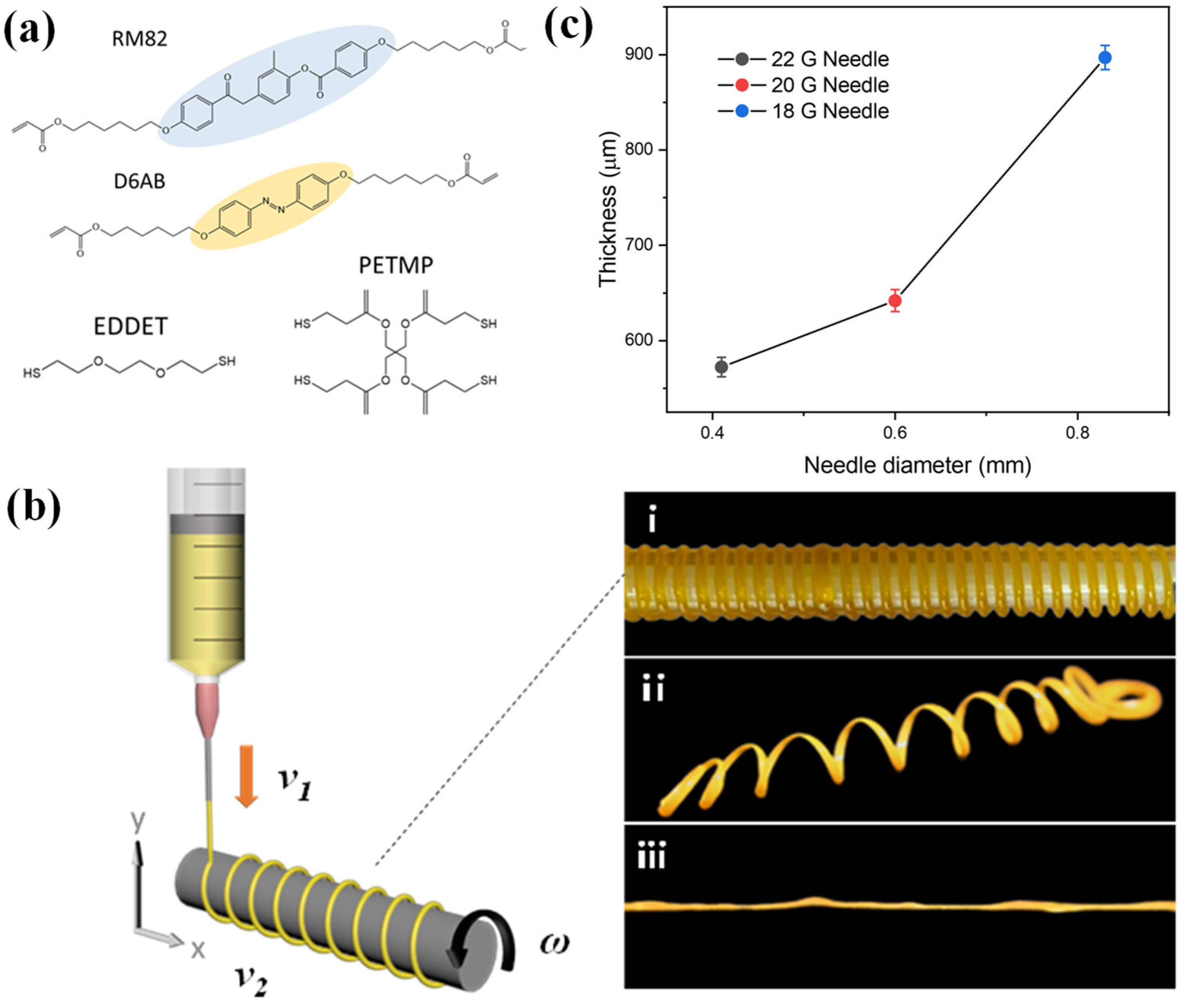
2.1. Materials

Reactive mesogen (RM) 1,4-Bis-[4-(6-acryloyloxyhexyloxy)benzoyloxy]-2-methylbenzene (RM82) was purchased from Sdyano (Shijiazhuang, China). Azobenzene derivative 4,4′diacrylolylhexyloxyazobenzene (D6AB) was purchased from Meryer (Shanghai, China). Flexible chain extender 2,2′-(ethylenedioxy)diethanethiol (EDDET), crosslinker pentaerythritol tetrakis(3-mercaptopropionate) (PETMP), dipropylamine (DPA), butylated hydroxytoluene (BHT), photoinitiator (PI) bis(cyclopenta-1,3-diene)bis(1-(2,4-difluorophen-yl)-3H-pyrrol-3-yl)titanium (Irgacure 784), sodium chloride (NaCl, ≥99.0%), sodium sulfate (Na2SO4, ≥99.0%), and all solvents used of HPLC purity (≥99.8%) were acquired from Sigma-Aldrich (Singapore). The chemical structure of monomers used to prepare the LCE ink is shown in Figure 1a, and all materials were used as received.

2.2. Synthesis of the LCE Ink

LCE ink was prepared through a two-step thiol-acrylate Michael addition reaction. RM82 (1.65 mmol, 1.000 g), D6AB (0.50 mmol, 0.259 g), BHT (0.11 mmol, 0.025 g), and EDDET (1.08 mmol, 0.197 g) were dissolved in 1.5 mL of dichloromethane (DCM) first. A catalyst DPA was diluted into toluene at a ratio of 1:20. After mixing and cooling down, the diluted DPA (0.137 g) solution was added to DCM to initiate the first-stage Michael addition reaction for 12 h in an air-tight glass bottle at room temperature. Then, PETMP (0.36 mmol, 0.176 g) and diluted DPA (0.046 g) were added into the solution and stirred for 3 h at room temperature to continue the second stage of the Michael addition reaction and crosslink with the acrylate-terminated groups of the oligomer. The molar ratio of acrylate groups to thiol groups n a c r y l a t e n t h i o l was kept at 1.1 for the reaction. Here, excess acrylate mesogens were required to ensure acylate termination and the following photo-crosslinking. Next, the mixture was rinsed with 1 M HCl aqueous solution twice and 0.1 M NaCl solution twice to remove DPA. It was then dried by anhydrous Na2SO4 powder and then filtered. The solvent was evaporated in an oven at 40 °C for 6 h to yield the final LC oligomer. Lastly, the LC oligomer was re-dissolved in DCM and mixed with the photoinitiator, Irgacure 784 (0.12 mmol, 0.065 g) to form the LCE ink. The concentration of the LCE ink was set to be 80 wt % to obtaint the desired viscosity.

2.3. Fabrication of the Coil-Shaped LC Oligomer

An extrusion system consisting of an injection needle and a collecting mandrel was applied for the fabrication of the LCE coil, as shown in Figure 1a. The LCE ink was first loaded into a 3 mL plastic syringe with a 20 G industrial blunt orifice needle (Braun, Frankfurt, Germany). A syringe pump (KD Scientific, Holliston, MA, USA) was used to control the extrusion speed of the LCE ink at ν1 = 0.65 mL min−1. A plastic syringe barrel with an outer diameter of 0.7 mm coated with a thin PVA layer was utilized as a collector to deposit the ink. It was achieved through the manual rubbing of 10 wt% aqueous solution of PVA (Mw = 89,000–98,000, 99+% hydrolyzed) with a brush, followed by drying at 100 °C for 30 min. The LCE ink was extruded from the syringe along the y-direction through the blunt orifice needle and collected on the mandrel, which was driven by a rolling motor at a constant rotation rate of 10 rpm. The distance between the needle and the mandrel was approximately 15 mms. Another syringe pump (Harvard Apparatus, Holliston, MA, USA) was used as an orbit for the lateral movement of the rolling motor along the x-direction at ν2 = 68 mm min−1. Through this extrusion–rolling process, a mandrel coated with an LC oligomer with a uniform thickness and spacing was obtained. It was incubated for 24 h at room temperature for annealing of the LC oligomer.

2.4. Fabrication of the LCE Coil

The mandrel coated with LC oligomer was submerged in water for 10 min to dissolve the PVA layer, making the LC oligomer detach from the mandrel. After that, it was suspended in the air until dry. The non-fully crosslinked coil-shaped LC oligomer was then straightened and stretched at 60% strain and polymerized to form the stretched LCE coil using visible light (532 nm, Haoyu Energy, Shenzhen, China) with an intensity of 10 mW cm−2 for 30 min.

2.5. Sample Characterization

The LCE coil was characterized by using scanning electron microscopy (SEM, JSM-7610F PLUS, JEOL, Akishima-shi, Japan). Its alignment was observed by using a polarizing optical microscope (POM, model LV100POL) manufactured by Nikon (Tokyo, Japan) under crossed polarizers. The sample was also characterized by using differential scanning calorimetry (DSC) manufactured by PerkinElmer (model 8500, Waltham, MA, USA). Samples were first heated from 30 °C to 150 °C to erase the thermal history and then cycled twice between 150 °C and −30 °C at a scanning rate of 10 °C min−1. UV–Vis absorbance spectra were recorded using a spectrophotometer (UV-2401PC, Shimadzu, Kyoto, Japan). The chemical structures of the LCE as well as the raw materials (RM82, EDDET, PETMP, and D6AB) were characterized by using a Fourier transform infrared (FTIR) spectrometer (Frontier) manufactured by PerkinElmer (Waltham, MA, USA). All spectra were recorded in the 400–4000 cm−1 range with 32 scans. Two-dimensional wide-angle X-ray diffraction (2D-WAXD) patterns were obtained by using an X-ray diffractometer (HomeLab, Rigaku, Osaka, Japan). The X-ray wavelength was 1.5405 Å and the angular range of the test was 4–30°.

3. Results and Discussion

3.1. Selection and Optimization of the LCE Ink

To fabricate a photo-responsive LCE coil, an extrusion–rolling method with LCE ink was developed. In this process, a highly viscous ink (~13–15 Pa·s) was extruded from a needle [42], and the coil was collected by using a roller rotating at a constant speed. To prepare an LCE coil with high flexibility, the composition of the ink was chosen based on following requirements: (1) flexible spacers must be incorporated to increase the elasticity and flexibility of the LC polymer; (2) the azobenzene molecule needs to be crosslinked with the main-chain LC oligomer to amplify the microscopic response [38]; (3) the ratio of the di-thiol chain extenders and tera-thiol crosslinkers should be adjusted to obtain proper strength and elasticity [43]; (4) the viscosity of the ink needs to be controlled to allow easy extrusion and molding [44].
On the basis of the above requirements, EDDET and PETMP were chosen as the flexible spacers. EDDET contains 2 thiol groups while PETMP contains 4 thiol groups, which can react with acrylate groups through a thiol-acrylate Michael addition reaction. For the azobenzene molecules, diacrylate azobenzene derivatives were chosen, because they can crosslink with thiol groups of EDDET and PETMP. The chain extension reaction occurred between the acrylate groups of the azobenzene, D6AB, and thiol groups of the chain extender, EDDET, and led to the formation of the azobenzene-incorporated main-chain LC oligomers. The chemical structures of the monomers are shown in Figure 1a.
Moreover, for a main-chain LCE, the elasticity and actuation performance are closely related to the network structure, which is determined by the chain extenders and crosslinkers. Therefore, it is important to adjust the ratio between di-thiol chain extenders, EDDET, and tera-thiol crosslinkers, PETMP, to control the oligomer length and crosslink density [43,45]. To determine the optimum concentration, the mole ratio between EDDET and PETMP was defined as follows:
r = n E D D E T n P E T M P
In this experiment, the value of r was varied from 5 to 1, while the ratio of total acrylate groups to total thiol groups in the mixture was kept at 1.1 in all experiments [46]. Different LCE inks were prepared by using a two-stage Michael addition reaction to form LCE oligomers. The result showed that increasing the amount of EDDET increased the oligomer length and decreased the crosslinking density. On the other hand, increasing the amount of PETMP enhanced the rigidity and strength of LCE [43,47]. This is because PETMP contains four terminal thiol groups. Hence, four thiol-acrylate linkages were created on each PETMP molecule during the second-stage Michael addition reaction. After curing, the fibrous LC oligomers were peeled off from the mandrel. However, when the value of r was 4 or 5, the LC oligomer only formed a straight fiber. It could not form a coil due to the lack of elasticity (Figure S1). With the decreasing r value, the proportion of PETMP continued to increase, and the LC oligomer started to form a coil due to the increase in rigidity. However, it became too stiff and fragile when the amount of PETMP was too high ( r = 1 or 3). This result shows that an increase in crosslinking density resulted in a decrease in elasticity and flexibility. Thus, r = 3 was selected as the optimal ratio of EDDET and PETMP in the subsequent study to obtain a flexible coil structure.
Furthermore, it was found that the viscosity of the LCE ink also influenced the quality of the coil formation. The viscosity of the ink can be controlled by using the solvent concentration [44]. The optimal concentration of LC oligomer in DCM to prepare LCE ink was determined to be 20 wt% in our experiment. If the amount of solvent was too low, the ink became too rigid to be extruded from the needle. If the amount of solvent was too high, the ink was too fluidic and “melted” on the collecting mandrel.

3.2. Effect of Extrusion Parameters on the Morphology of LCE Coil

To produce the azobenzene-functionalized LCE coil with a uniform thickness and controllable shape dimension, we developed an extrusion–rolling system as shown in Figure 1b. The LCE ink was extruded through the needle at a speed ν1 controlled by a syringe pump. After dropping onto the collecting mandrel, which rotated at a constant speed ω, the ink was stretched and wound onto the mandrel. Another syringe pump was utilized to push forward the rolling motor at ν2 to enable continuous collection of the LCE ink. The detailed process was provided in the Supplementary Video S1. During the fabrication process, it is important to control the extrusion parameters to obtain a desirable coil-shaped LC oligomer, including ω, ν1, and ν2, and the needle size.
By applying blunt needles with different gauges (18/20/22 G), a series of coil-shaped LC oligomers with different diameters was obtained. The inner diameters of the 18/20/22 G needles were 0.83 mm, 0.6 mm, and 0.41 mm, and they extruded LC oligomers with diameters of 897.01 ± 12.70 µm, 641.89 ± 11.57 µm, and 572.3 ± 10.18 µm, respectively (Figure S2). It showed that the wider the needle diameter, the thicker the coil. However, mesogens inside a thick coil had a poor alignment (Figure S3), while a thin coil was too fragile to be handled for further processing. As a result, the coil-shaped LC oligomer obtained using a 20 G needle with a 0.6 mm diameter was used for subsequent studies.
A series of experiments was also carried out to adjust the values of ω, ν1, and ν2. Adjustment of the speed ω changes the coil diameter from microns to millimeters at a constant extrusion speed, and the coil helicity is directly affected by the coil diameter. To obtain LCE coils with diameters in the micrometer range, the rotational speed ω was fixed at 10 rpm. In order to provide a steady force to extrude the LCE ink, the extrusion speed ν1 was fixed at 0.65 mL min−1. If ν1 was too fast, it caused overlapping of ink on the mandrel. On the other hand, if ν1 was too slow, it was difficult to extrude the ink. When the rotation rate ω was kept at 10 rpm, the driving speed ν2 was adjusted from 60 to 80 mm min−1 to enable continuous winding of the LCE ink. However, a high driving speed also resulted in large spacing between the fibers and reduced the degree of helix. On the contrary, a low driving speed led to little spacing or overlapping of inks (Figure S3). Therefore, after a series of experiments, optimal parameters were determined to be ν1 = 0.65 mL min−1, ν2 = 68 mm min−1, and ω = 10 rpm. By using the parameters, a coil-shaped LC oligomer with a diameter of approximately 0.6 mm was obtained.
The extrusion–rolling process was accompanied by a multi-stage crosslinking process to form a well-aligned, fully crosslinked LCE coil, as illustrated in Figure 2. During the extrusion process of the isotropic LCE ink from the needle, a shear stress-induced preliminary alignment of the LC oligomer was induced [32,48]. After curing at room temperature, the LC oligomer was peeled off from the mandrel. Owing to the presence of the flexible spacers EDDET and PETMP at the optimized proportion, a coil structure was well maintained, as shown in Figure 1c. Next, it was straightened and stretched with 60% strain to 1.6 times the original length to achieve uniaxial alignment of the LC mesogens (Figure S4a,b). The partially crosslinked LC oligomer was then polymerized under visible light (532 nm) to crosslink excess acrylate groups to form a fully crosslinked stretched LCE coil (Figure S4c,d). Following the approach, a uniaxial alignment of the LC mesogens was obtained. The uniform alignment was characterized by using 2D-WAXD as shown in Figure S5b. The stretched LCE coil was used as a soft actuator in the following experiments.
Figure 3a,b shows the polarized optical microscope (POM) images of a section of the LCE coil, which was placed at 45° and 0°, respectively. The obvious difference in the brightness suggests that the stretched LCE coil exhibits anisotropic properties, and it is well-aligned along the stretched direction. However, the unstretched coil-shaped LC oligomer exhibits relatively poor alignment (Figure S5c,d). The well-aligned orientation of the coil was also verified through the results of the 2D WAXD measurement (Figure S5a,b). The diameter of the coil is 375 µm, which is about 60% of the original diameter of the coil-shaped LC oligomer. Furthermore, we cut the coil into small pieces and studied the scanning electron microscopy (SEM) images from different cross sections (Figure 3c,d). It can be seen that the side cross section of the coil formed a compressed semi-cylindrical shape, which was attributed to the automatic deposition of the precursor on the cylindrical roller and the solvent evaporation induced de-swelling [44].

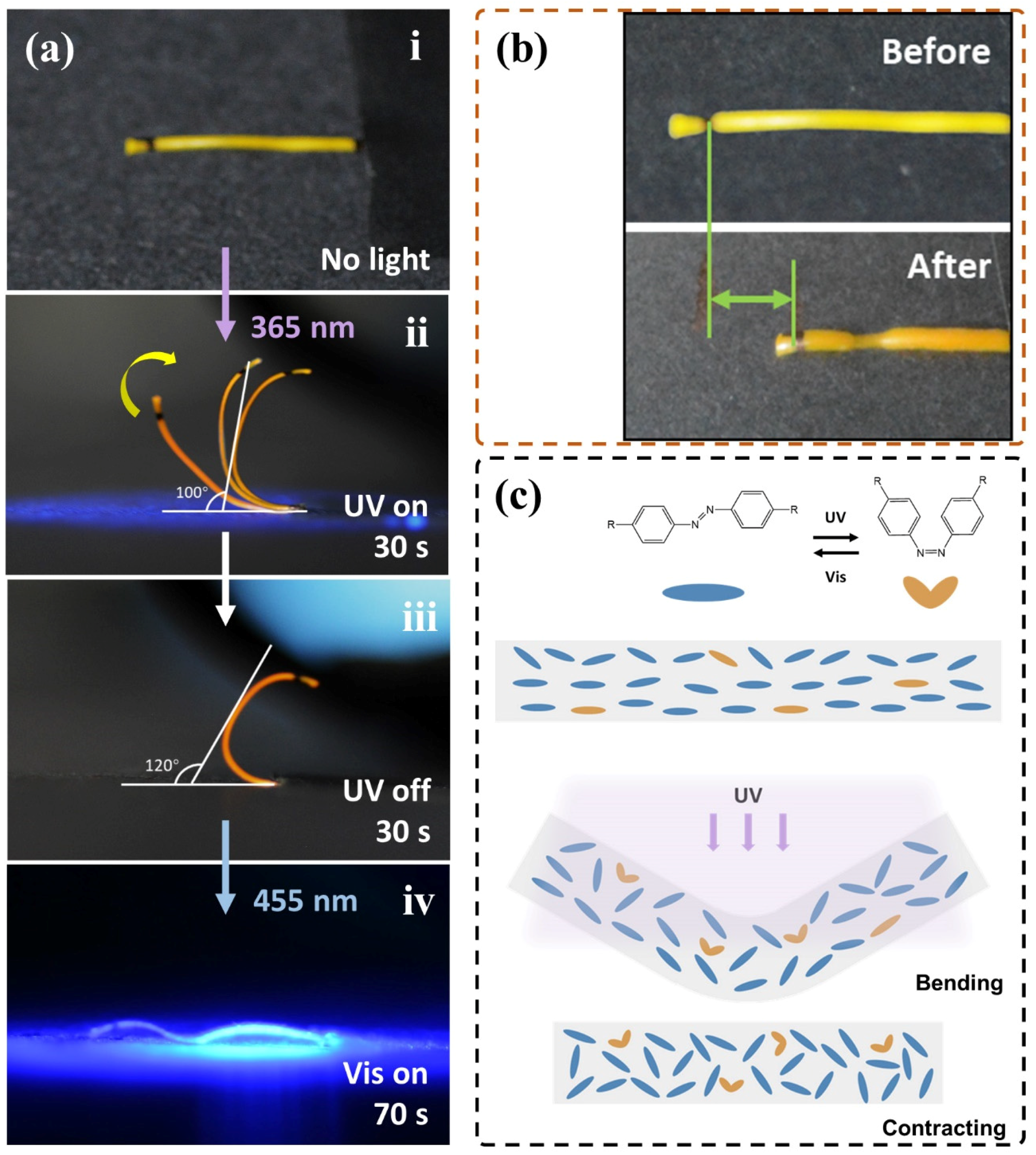
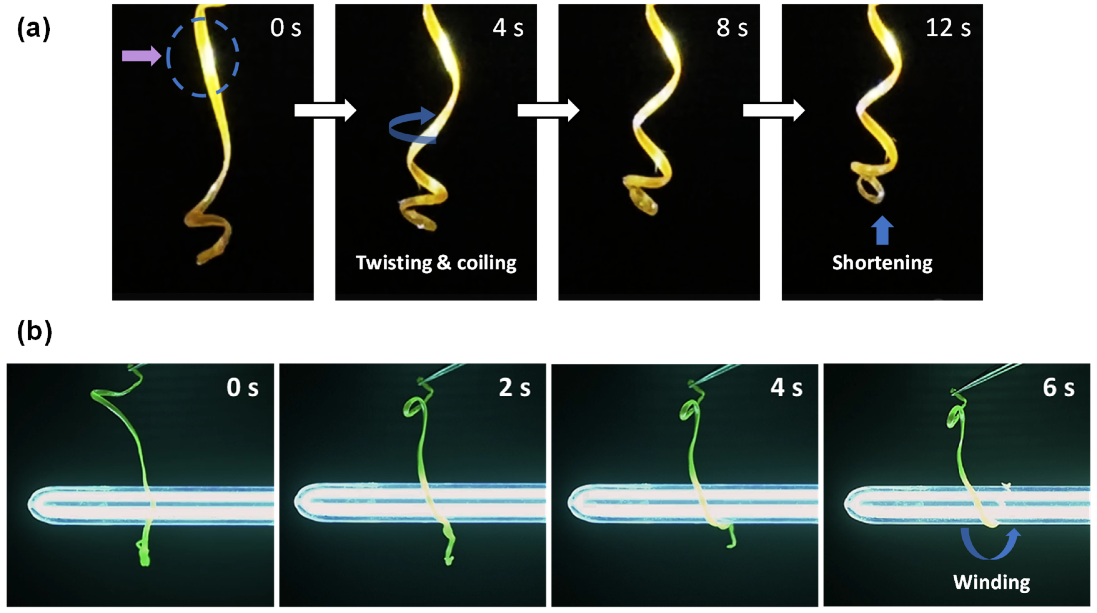
3.3. Photomechanical Response of the LCE Coil to UV Light

Next, we investigated the photomechanical response of the LCE by irradiating a small piece of the stretched LCE coil, which was 2 cm long. Upon illumination with UV light (365 nm, 10 mW cm−2) to an area of 12 cm2 at room temperature, it began to bend towards the light source. As shown in Figure 4a, with an increasing exposure time from 30 to 90 s, the degree of bending gradually increased from 30° to 100°. The phenomenon was due to the trans-cis isomerization of the azobenzene moiety triggered by UV light, and that led to disruption of the order of LC mesogens at the exposure site. Since azobenzene exhibits a high extinction coefficient, most of the incident light was absorbed within a thin layer. Therefore, the isomerization behavior mainly began from the exposure site, and a gradient distribution of the mesogens can be induced [49,50]. As a result, an anisotropic contraction at the exposure site and a bending deformation were achieved (Figure 4c).
Even after the removal of the UV light, the stretched LCE coil still continued to bend to 120° in 30 s. This bending state remained until the coil was exposed to visible light. This temporarily stable state could be attributed to the remaining stress generated by the cis-isomer [16,51]. Upon visible light illumination (455 nm, 10 mW cm−2), the coil reversed back to a flat state gradually (Figure S6). This is due to photoinduced trans isomerization of the cis azobenzene moieties, resulting in mechanical relaxation and large unbending deformations. Moreover, it was noted that the length of the coil became shorter, and the color changed from light yellow to dark orange after the light illumination. A 30% contraction of the coil in length occurred (Figure 4b). This contraction can be related to the trans-cis isomerization of the azobenzene derivatives inside the LCE coil as well as the photothermal effect, leading to a disturbance of the molecular order of LC mesogens [52,53].
Through the investigation of macroscopic motions of the stretched LCE coils, a mechanism of bending and contracting behaviors was proposed and shown in Figure 4c. According to reports, the initial arrangement of the azobenzene mesogens is an important factor influencing the bending behavior of the LCE [54]. Due to the presence of the azobenzene cross-linking agent and its geometrical conversion from trans to cis isomer under UV irradiation (Figure S7), the degree of ordering of the LC mesogens decreases, which leads to the deformation of the shape of the LCE, and LCEs with azobenzene parallel arrangement bend toward the UV light source. Upon UV illumination from the top, the order of the mesogens at the top layer is likely to be disturbed, leading to an anisotropic contraction along the alignment direction and an expansion at the bottom side. Thus, the stretched LCE coil bent towards the direction of light [55,56].
It is expected that the shape deformation could be amplified by using an LCE coil, which was 8 cm long. To investigate the deformation behavior, a UV light (365 nm, 100 mW cm−2) with a spot size of 0.5 cm2 was directed to a section of the coil. As shown in Figure 5a, once it was illuminated by the UV light, it began to twist rapidly. Eventually, it coiled up and became shorter along the longitudinal direction in 12 s. This shape deformation was also due to the conformational change of the azobenzene isomer, inducing anisotropic contraction along the molecular director, thereby converting the absorbed light energy into mechanical work [57,58]. Due to the relatively high azobenzene content, a cis-trans gradient is created throughout the coil, resulting in contraction of the exposed side. The anisotropic contraction at each small piece of the coil was then accumulated and converted to the macroscopic contraction of the entire coil, thereby leading to the coiling behavior.
This behavior suggests to us that these LCE coils have similarities with some behaviors of plant tendrils. In sunny or warm environments, plant tendrils climb along the branches. When a UV lamp is used as an excitation light source, the stretched LCE coil undergoes molecular isomerization when approaching the lamp, causing it to quickly bend and wrap around the lamp (Supplementary Video S2). Notably, the heat source tube can also cause the LCE coil to undergo phase-transition curling, resulting in a similar climbing behavior. In terms of the characteristics of excitation spectra and actuation behavior, LCE coils are equivalent to plant tendrils. Therefore, it is expected that this LCE coil can be used to develop biomimetic systems with curling and climbing abilities, which behave similarly to plant tendrils.
In addition, the isotropic phase transition temperature of the LCE coil can be reached at 110 °C using DSC measurement (Figure S8a). Thus, we set a heating gradient to study the shape deformation of the LCE coil. In this experiment, the coil was loosely placed on a hot plate with an initial length of 5.8 cm (Figure S8b). During the heating process, the coil contracted significantly above 80 °C (Figure S8c); this is because some of the mesogen units of the coil entered an isotropic state. When the temperature reached 120 °C, the coil contracted to 1.9cm, and the shrinkage rate reached 67.2% (Figure S8e). Furthermore, the process of the shape deformation is reversible, which indicates that the LCE coil also has a thermomechanical response characteristic. It is expected that this LCE coil can also be applied in developing a biomimetic system that behaves like albuca spiralis with the ability to perceive temperature and achieve curling–relaxation behavior.

4. Conclusions

In this paper, we developed a light-responsive coil by using LCE doped with azobenzene. This coil exhibited a variety of photo-induced motions, including contracting, bending, twisting, and coiling. This shape deformation was attributed to the photomechanical response of the azobenzene derivatives and the change in molecular order of the LC mesogens at the exposure site. The uniform aligned LCE coil was formed by polymerization and stretching of the coil-shaped LC oligomer with 60% strain. To obtain the LCE with good strength as well as elasticity, the composition of the LCE ink was adjusted to fabricate the coil-shaped LC oligomers through an extrusion–rolling process. It was demonstrated that this fibrous actuator performed reversible bending behavior up to 120° towards the light source and 30% contraction upon UV light exposure. Moreover, it was able to twist, coil, or even wind rapidly onto a tube under UV light illumination, making it applicable to fabricate a biomimetic robotic tendril that mimics the tropism movement of the climbing plants. This fibrous actuator can also respond to temperature changes to a certain extent, making it suitable for the application as a biomimetic system like albuca spiralis. This biomimetic fibrous actuator exhibits a high degree of freedom, fast response, shape memory property, and diverse deformations. Efforts are still required to systematically study its coiling behaviors and the motion modes. It is also worth applying functional design based on its unique deformation behaviors to fabricate soft actuators and biomimetic plants.

Supplementary Materials

The following supporting information can be downloaded at https://www.mdpi.com/article/10.3390/act14040171/s1. Supplementary Figures: Figure S1. Coil-shaped LC oligomers formed through Michael addition reactions with different mole ratios between EDDET and PETMP ( r = n E D D E T n P E T M P ). A relatively poor coil shape was formed when the value of r was (a) 5, (b) 4, (c) 2, and (d) 1. Figure S2. LC oligomers fabricated by blunt needles with different gauges, leading to the formation of the coil-shaped LC oligomers with thicknesses of (a) 897.01 ± 12.70 µm, (b) 641.89 ± 11.57 µm, and (c) 572.3 ± 10.18 µm, respectively. Figure S3. (a,b) POM images of the coil-shaped LC oligomer with a large thickness above 900 µm. The long axis of the coil was placed at (a) 45°and (b) 0° to the polarizer. (c) A negative example of the LC oligomer formed on the mandrel, which joined together and was non-uniform. Figure S4. Stretching and secondary photopolymerization of (a) the LC oligomer to form (b) the LCE coil. (c) The optical images of the LCE coil before and after stretching and secondary photo-polymerization. (d) FTIR spectra of the materials used in the fabrication of the LCE. Figure S5. 2D-WAXD patterns of the (a) coil-shaped LC oligomer and (b) the stretched LCE fiber. (c,d) POM images of the unstretched LC oligomer between crossed polarizers. Its long axis is placed at (c) 0° and (d) 45° to the polarizer. Figure S6. Photographs of the reversible unbending behavior at different times of the LCE coil fiber induced by visible light (455 nm). Figure S7. UV–Vis absorption spectra of the (a) D6AB molecule and the (c) azoben-zene-functionalized LC oligomer dissolved in DCM (50 ppm) before and after UV exposure (100 mW cm−2, 5 s), and followed by visible light exposure (532 nm) at different times (tvis). The inset arrows represent the increase in tvis. The absorbances of (b) the D6AB molecules and (d) the azo-benzene-functionalized LC oligomer dissolved in DCM (50 ppm) at 355 nm and 455 nm after visible light exposure for different times (tvis). Figure S8. (a) DSC thermograms of the LC oligomer and the LCE. Photographs of the reversible contraction behavior of the LCE coil under different temperatures. (b) 23 °C (room temperature), (c) 80 °C, (d)100 °C, and (e) 120 °C. Supplementary Notes: Supplementary Note S1: Characterization. Supplementary Note S2: Photoisomerization of the azobenzene derivative [28,59]. Supplementary videos legends: Video S1. Fabrication process of the coil-shaped LC oligomer through a spinning system. With an LCE ink extruded from a syringe and deposited on a rotating mandrel. Video S2. Process of the LCE coil bend and wind onto a UV light tube in 6 s, which behaves like a plant tendril.

Author Contributions

Conceptualization, J.Z. and Z.Z.; Funding acquisition, Z.Z. and K.-L.Y.; Methodology, X.Z. and J.L.; Writing—original draft, X.Z. and Z.R.; Writing—review and editing, Z.Z. and K.-L.Y. All authors have read and agreed to the published version of the manuscript.

Funding

This research was funded by the following grants: Academic Research Fund Tier-1, A-8000187-01-00; China Postdoctoral Science Foundation (Certificate Number: 2024M764200); Postdoctoral Fellowship Program of CPSF under Grant Number GZC20242199; China National Key R&D Program during the 14th Five-year Plan Period (Grant No. 2023YFB3811600).

Data Availability Statement

The original contributions presented in this study are included in the article/Supplementary Material. Further inquiries can be directed to the corresponding authors.

Conflicts of Interest

The authors declare no conflicts of interest.

Abbreviations

LC, liquid crystal; LCE, liquid crystal elastomer; LCP, liquid crystal polymer; RM, reactive mesogen; UV, ultraviolet; DIW, direct ink write.

References

  1. Gilroy, S. Plant tropisms. Curr. Biol. 2008, 18, R275–R277. [Google Scholar] [PubMed]
  2. Gerbode, S.J.; Puzey, J.R.; McCormick, A.G.; Mahadevan, L. How the Cucumber Tendril Coils and Overwinds. Science 2012, 337, 1087–1091. [Google Scholar] [PubMed]
  3. Wang, W.; Li, C.; Cho, M.; Ahn, S.-H. Soft Tendril-Inspired Grippers: Shape Morphing of Programmable Polymer–Paper Bilayer Composites. ACS Appl. Mater. Interfaces 2018, 10, 10419–10427. [Google Scholar] [PubMed]
  4. Cheng, Y.; Wang, R.; Chan, K.H.; Lu, X.; Sun, J.; Ho, G.W. A Biomimetic Conductive Tendril for Ultrastretchable and Integratable Electronics, Muscles, and Sensors. ACS Nano 2018, 12, 3898–3907. [Google Scholar]
  5. Must, I.; Sinibaldi, E.; Mazzolai, B. A variable-stiffness tendril-like soft robot based on reversible osmotic actuation. Nat. Commun. 2019, 10, 344. [Google Scholar]
  6. Walker, J.; Zidek, T.; Harbel, C.; Yoon, S.; Strickland, F.S.; Kumar, S.; Shin, M. Soft Robotics: A Review of Recent Developments of Pneumatic Soft Actuators. Actuators 2020, 9, 3. [Google Scholar] [CrossRef]
  7. Edward, S.; Golecki, H.M. Gelatin Soft Actuators: Benefits and Opportunities. Actuators 2023, 12, 63. [Google Scholar] [CrossRef]
  8. Zhang, P.; Wang, G.; Yu, H. Ultraviolet-visible-near-infrared light-responsive soft materials: Fabrication, photomechanical deformation and applications. Responsive Mater. 2024, 2, e20240016. [Google Scholar]
  9. Tateyama, A.; Nakanishi, T. Responsive molecular liquid materials. Responsive Mater. 2023, 1, e20230001. [Google Scholar]
  10. Zhang, Y.; Zheng, Z.-G.; Li, Q. Multiple degrees-of-freedom programmable soft-matter-photonics: Configuration, manipulation, and advanced applications. Responsive Mater. 2024, 2, e20230029. [Google Scholar]
  11. McCracken, J.M.; Donovan, B.R.; White, T.J. Materials as Machines. Adv. Mater. 2020, 32, 1906564. [Google Scholar]
  12. Sánchez-Ferrer, A. Liquid Crystal Elastomers: Materials and Applications; de Jeu, W.H., Ed.; Springer: Berlin/Heidelberg, Germany, 2014; Volume 23, pp. 44–45. [Google Scholar]
  13. Han, D.; Wang, X.; Liu, S.; Zhang, Y.; Li, C.; Gao, Y.; Zhang, J. Mechanochromic Response of Spiropyran-Incorporated Liquid Crystalline Elastomer Network and the Mechanochromic Enhancement by Nano Zinc Oxide. Adv. Mater. Technol. 2023, 8, 2300175. [Google Scholar]
  14. Ryabchun, A.; Li, Q.; Lancia, F.; Aprahamian, I.; Katsonis, N. Shape-Persistent Actuators from Hydrazone Photoswitches. J. Am. Chem. Soc. 2019, 141, 1196–1200. [Google Scholar] [PubMed]
  15. Ahn, S.K.; Ware, T.H.; Lee, K.M.; Tondiglia, V.P.; White, T.J. Photoinduced Topographical Feature Development in Blueprinted Azobenzene-Functionalized Liquid Crystalline Elastomers. Adv. Funct. Mater. 2016, 26, 5819–5826. [Google Scholar]
  16. Pilz da Cunha, M.; Debije, M.G.; Schenning, A.P.H.J. Bioinspired light-driven soft robots based on liquid crystal polymers. Chem. Soc. Rev. 2020, 49, 6568–6578. [Google Scholar]
  17. Ube, T.; Kawasaki, K.; Ikeda, T. Photomobile Liquid-Crystalline Elastomers with Rearrangeable Networks. Adv. Mater. 2016, 28, 8212–8217. [Google Scholar]
  18. Wie, J.J.; Shankar, M.R.; White, T.J. Photomotility of polymers. Nat. Commun. 2016, 7, 13260. [Google Scholar]
  19. Iamsaard, S.; Aßhoff, S.J.; Matt, B.; Kudernac, T.; Cornelissen, J.J.L.M.; Fletcher, S.P.; Katsonis, N. Conversion of light into macroscopic helical motion. Nat. Chem. 2014, 6, 229–235. [Google Scholar]
  20. Wang, M.; Lin, B.-P.; Yang, H. A plant tendril mimic soft actuator with phototunable bending and chiral twisting motion modes. Nat. Commun. 2016, 7, 13981. [Google Scholar]
  21. Aßhoff, S.J.; Lancia, F.; Iamsaard, S.; Matt, B.; Kudernac, T.; Fletcher, S.P.; Katsonis, N. High-Power Actuation from Molecular Photoswitches in Enantiomerically Paired Soft Springs. Angew. Chem. Int. Ed. 2017, 56, 3261–3265. [Google Scholar]
  22. Yu, Y.; Nakano, M.; Ikeda, T. Directed bending of a polymer film by light. Nature 2003, 425, 145. [Google Scholar] [PubMed]
  23. Sawa, Y.; Ye, F.; Urayama, K.; Takigawa, T.; Gimenez-Pinto, V.; Selinger, R.L.B.; Selinger, J.V. Shape selection of twist-nematic-elastomer ribbons. Proc. Natl. Acad. Sci. USA 2011, 108, 6364–6368. [Google Scholar] [PubMed]
  24. Lee, K.M.; Bunning, T.J.; White, T.J. Autonomous, Hands-Free Shape Memory in Glassy, Liquid Crystalline Polymer Networks. Adv. Mater. 2012, 24, 2839–2843. [Google Scholar] [PubMed]
  25. Wang, Y.; Sun, J.; Liao, W.; Yang, Z. Liquid Crystal Elastomer Twist Fibers toward Rotating Microengines. Adv. Mater. 2022, 34, 2107840. [Google Scholar]
  26. Ma, J.; Yang, Z. Smart liquid crystal elastomer fibers. Matter 2025, 8, 101950. [Google Scholar]
  27. Cho, E.-H.; Luu, K.; Park, S.-Y. Mechano-Actuated Light-Responsive Main-Chain Liquid Crystal Elastomers. Macromolecules 2021, 54, 5397–5409. [Google Scholar]
  28. Luu, K.; Park, S.-Y. Shape-Persistent Liquid Crystal Elastomers with Cis-Stable Crosslinkers Containing Ortho-Methyl-Substituted Azobenzene. Macromolecules 2023, 56, 1324–1338. [Google Scholar]
  29. Ma, J.; Wang, Y.; Sun, J.; Yang, Z. Liquid Crystal Elastomer Hollow Fibers as Artificial Muscles with Large and Rapid Actuation Enabled by Thermal-Pneumatic Enhanced Effect. Adv. Funct. Mater. 2024, 34, 2402403. [Google Scholar]
  30. Liu, F.; Urban, M.W. Recent advances and challenges in designing stimuli-responsive polymers. Prog. Polym. Sci. 2010, 35, 3–23. [Google Scholar]
  31. Ambulo, C.P.; Burroughs, J.J.; Boothby, J.M.; Kim, H.; Shankar, M.R.; Ware, T.H. Four-dimensional Printing of Liquid Crystal Elastomers. ACS Appl. Mater. Interfaces 2017, 9, 37332–37339. [Google Scholar]
  32. Kotikian, A.; Truby, R.L.; Boley, J.W.; White, T.J.; Lewis, J.A. 3D Printing of Liquid Crystal Elastomeric Actuators with Spatially Programed Nematic Order. Adv. Mater. Technol. 2018, 30, 1706164. [Google Scholar] [CrossRef] [PubMed]
  33. Roach, D.J.; Yuan, C.; Kuang, X.; Li, V.C.; Blake, P.; Romero, M.L.; Hammel, I.; Yu, K.; Qi, H.J. Long Liquid Crystal Elastomer Fibers with Large Reversible Actuation Strains for Smart Textiles and Artificial Muscles. ACS Appl. Mater. Interfaces 2019, 11, 19514–19521. [Google Scholar] [CrossRef] [PubMed]
  34. Liao, W.; Yang, Z. 3D printing programmable liquid crystal elastomer soft pneumatic actuators. Mater. Horiz. 2023, 10, 576–584. [Google Scholar] [CrossRef] [PubMed]
  35. He, Q.; Wang, Z.; Wang, Y.; Wang, Z.; Li, C.; Annapooranan, R.; Zeng, J.; Chen, R.; Cai, S. Electrospun liquid crystal elastomer microfiber actuator. Sci. Rob. 2021, 6, eabi9704. [Google Scholar] [CrossRef]
  36. Hou, W.; Wang, J.; Lv, J.A. Bioinspired Liquid Crystalline Spinning Enables Scalable Fabrication of High-Performing Fibrous Artificial Muscles. Adv. Mater. 2023, 35, e2211800. [Google Scholar] [CrossRef]
  37. Gelebart, A.H.; Mc Bride, M.; Schenning, A.P.H.J.; Bowman, C.N.; Broer, D.J. Photoresponsive Fiber Array: Toward Mimicking the Collective Motion of Cilia for Transport Applications. Adv. Funct. Mater. 2016, 26, 5322–5327. [Google Scholar] [CrossRef]
  38. del Pozo, M.; Liu, L.; Pilz da Cunha, M.; Broer, D.J.; Schenning, A.P.H.J. Direct Ink Writing of a Light-Responsive Underwater Liquid Crystal Actuator with Atypical Temperature-Dependent Shape Changes. Adv. Funct. Mater. 2020, 30, 2005560. [Google Scholar] [CrossRef]
  39. Kim, I.H.; Choi, S.; Lee, J.; Jung, J.; Yeo, J.; Kim, J.T.; Ryu, S.; Ahn, S.-K.; Kang, J.; Poulin, P.; et al. Human-muscle-inspired single fibre actuator with reversible percolation. Nat. Nanotechnol. 2022, 17, 1198–1205. [Google Scholar] [CrossRef]
  40. Wu, D.; Zhang, Y.; Yang, H.; Wei, A.; Zhang, Y.; Mensah, A.; Yin, R.; Lv, P.; Feng, Q.; Wei, Q. Scalable functionalized liquid crystal elastomer fiber soft actuators with multi-stimulus responses and photoelectric conversion. Mater. Horiz. 2023, 10, 2587–2598. [Google Scholar] [CrossRef]
  41. Liu, L.; del Pozo, M.; Mohseninejad, F.; Debije, M.G.; Broer, D.J.; Schenning, A.P.H.J. Light Tracking and Light Guiding Fiber Arrays by Adjusting the Location of Photoresponsive Azobenzene in Liquid Crystal Networks. Adv. Opt. Mater. 2020, 8, 2000732. [Google Scholar] [CrossRef]
  42. Dong, X.; Zhou, X.; Li, L.; Cao, X.; Xu, J.; Dai, S.; Jiang, Y.; Li, Q.; Yuan, N.; Ding, J. Monodomain liquid crystal elastomer bionic muscle fibers with excellent mechanical and actuation properties. iScience 2023, 26, 106357. [Google Scholar] [PubMed]
  43. Hong, H.-J.; Park, S.-Y. Effects of network structure of main-chain liquid crystal elastomer on its thermal actuation performance. J. Ind. Eng. Chem. 2022, 110, 424–433. [Google Scholar] [CrossRef]
  44. Geng, Y.; Kizhakidathazhath, R.; Lagerwall, J.P.F. Robust cholesteric liquid crystal elastomer fibres for mechanochromic textiles. Nat. Mater. 2022, 21, 1441–1447. [Google Scholar] [PubMed]
  45. Liu, Y.; Ma, J.; Yang, Y.; Valenzuela, C.; Zhang, X.; Wang, L.; Feng, W. Smart chiral liquid crystal elastomers: Design, properties and application. Smart Mol. 2024, 2, e20230025. [Google Scholar]
  46. del Pozo, M.; Sol, J.A.H.P.; Schenning, A.P.H.J.; Debije, M.G. 4D Printing of Liquid Crystals: What’s Right for Me? Adv. Mater. 2021, 34, 2104390. [Google Scholar] [CrossRef]
  47. Yakacki, C.M.; Nair, D.P.; Torbati, A.H.; Saed, M.O. Synthesis of Programmable Main-chain Liquid-crystalline Elastomers Using a Two-stage Thiol-acrylate Reaction. J Vis Exp. 2016, 107, e53546. [Google Scholar]
  48. Wang, Z.; Wang, Z.; Zheng, Y.; He, Q.; Wang, Y.; Cai, S. Three-dimensional printing of functionally graded liquid crystal elastomer. Sci. Adv. 2020, 6, eabc0034. [Google Scholar] [CrossRef]
  49. Yu, Y.; Ikeda, T. Soft Actuators Based on Liquid-Crystalline Elastomers. Angew. Chem. Int. Ed. 2006, 45, 5416–5418. [Google Scholar]
  50. Yoshino, T.; Kondo, M.; Mamiya, J.I.; Kinoshita, M.; Yu, Y.; Ikeda, T. Three-Dimensional Photomobility of Crosslinked Azobenzene Liquid-Crystalline Polymer Fibers. Adv. Mater. 2010, 22, 1361–1363. [Google Scholar]
  51. Lu, X.; Zhang, H.; Fei, G.; Yu, B.; Tong, X.; Xia, H.; Zhao, Y. Liquid-Crystalline Dynamic Networks Doped with Gold Nanorods Showing Enhanced Photocontrol of Actuation. Adv. Mater. 2018, 30, 1706597. [Google Scholar] [CrossRef]
  52. Yue, Y.; Norikane, Y.; Azumi, R.; Koyama, E. Light-induced mechanical response in crosslinked liquid-crystalline polymers with photoswitchable glass transition temperatures. Nat. Commun. 2018, 9, 3234. [Google Scholar] [PubMed]
  53. Lugger, S.J.D.; Ceamanos, L.; Mulder, D.J.; Sánchez-Somolinos, C.; Schenning, A.P.H.J. 4D Printing of Supramolecular Liquid Crystal Elastomer Actuators Fueled by Light. Adv. Mater. Technol. 2022, 8, 2201472. [Google Scholar]
  54. Kondo, M.; Yu, Y.L.; Ikeda, T. How does the initial alignment of mesogens affect the photoinduced bending behavior of liquid-crystalline elastomers? Angew. Chem. Int. Ed. 2006, 45, 1378–1382. [Google Scholar]
  55. White, T.J.; Broer, D.J. Programmable and adaptive mechanics with liquid crystal polymer networks and elastomers. Nat. Mater. 2015, 14, 1087–1098. [Google Scholar]
  56. Ikeda, T.; Mamiya, J.I.; Yu, Y. Photomechanics of Liquid-Crystalline Elastomers and Other Polymers. Angew. Chem. Int. Ed. 2007, 46, 506–528. [Google Scholar]
  57. White, T.J. Photomechanical Effects in Liquid-Crystalline Polymer Networks and Elastomers. In Photomechanical Materials, Composites, and Systems; John Wiley & Sons, Ltd.: Hoboken, NJ, USA, 2017; pp. 153–177. [Google Scholar]
  58. Dattler, D.; Fuks, G.; Heiser, J.; Moulin, E.; Perrot, A.; Yao, X.; Giuseppone, N. Design of Collective Motions from Synthetic Molecular Switches, Rotors, and Motors. Chem. Rev. 2019, 120, 310–433. [Google Scholar]
  59. Beharry, A.A.; Woolley, G.A. Azobenzene photoswitches for biomolecules. Chem. Soc. Rev. 2011, 40, 4422. [Google Scholar]
Figure 1. (a) Molecular structures of the reactive mesogens and flexible spacers for preparing the LCE ink. (b) Schematic of the fabrication process of coil-shaped LC oligomer through an extrusion–rolling system, where ν1 is the extrusion speed of the LCE ink from the needle, ν2 is the moving speed of the rolling motor, and ω is the rotation speed of the collecting mandrel. Photographs of (i,ii) the formed coil-shaped LC oligomer and (iii) the stretched LCE coil used as the soft actuator. (c) The relationship between the thickness of the coil-shaped LC oligomers and the needle diameter.
Actuators 14 00171 g001
Figure 2. Schematic illustration of the multi-stage crosslinking process for preparation of the LCE coil. (a) In the LCE ink, the LC mesogens exhibited polydomain, and it was non-fully crosslinked. (b) After extruding through the system, the LC mesogens were roughly aligned by the shear stress and formed a coil-shaped LC oligomer. (c) The LC mesogens achieved uniaxial alignment after stretching-induced alignment and photopolymerization by visible light at 532 nm, forming the fully crosslinked LCE coil.
Actuators 14 00171 g002
Figure 3. (a,b) POM images of the stretched LCE coil between crossed polarizers. The long axis of the LCE coil is placed at (a) 45°and (b) 0° to the polarizer. (Scale bar = 200 µm) (c,d) SEM images of (c) a small piece of the LCE coil and (d) its cross-section.
Actuators 14 00171 g003
Figure 4. (a) Photographs showing (i) the initial 2 cm stretched LCE coil; (ii) UV light (365 nm) induced bending behavior; (iii) continuous bending motion after removal of UV light; (iv) visible light (455 nm) induced unbending behavior. (b) Contraction of the stretched LCE coil after light illumination. (c) Schematic illustration of the light-induced bending and contracting behavior of the LCE coil.
Actuators 14 00171 g004
Figure 5. (a) Photographs of the LCE coil showing the twisting and coiling behavior under UV light (365 nm) irradiation. (b) A biomimetic robotic tendril made from the LCE coil. It can wind onto the UV light tube rapidly.
Actuators 14 00171 g005
Disclaimer/Publisher’s Note: The statements, opinions and data contained in all publications are solely those of the individual author(s) and contributor(s) and not of MDPI and/or the editor(s). MDPI and/or the editor(s) disclaim responsibility for any injury to people or property resulting from any ideas, methods, instructions or products referred to in the content.

