Article

Automatic PLC Control Logic Generation Method Based on SysML System Design Model

1
School of Mechanical Engineering, Hangzhou Dianzi University, Hangzhou 310018, China
2
School of Mechanical Engineering, Hangzhou Dianzi University Information Engineering College, Hangzhou 311305, China
3
State Key Laboratory of Digital Manufacturing Equipment and Technology, Huazhong University of Science and Technology, Wuhan 430074, China
*
Author to whom correspondence should be addressed.
Actuators 2025, 14(5), 201; https://doi.org/10.3390/act14050201
Submission received: 11 March 2025 / Revised: 13 April 2025 / Accepted: 21 April 2025 / Published: 22 April 2025
(This article belongs to the Section Control Systems)

Abstract

:
Automatic generation of Programmable Logic Controller (PLC) programs from system design models can reduce system development costs and shorten system development cycles. However, effective methods for ensuring the quality and performance of control logic automatically generated from system design models are still lacking. This paper proposed a model-driven PLC program automatic generation approach. Firstly, a clear formal specification for the system design model oriented to PLC programming was established. Secondly, the fundamental semantic correspondence between system model elements and PLC program elements was defined by devising a set of mapping rules. Thirdly, a novel mapping algorithm was proposed to generate a PLC program based on system design models. Finally, an example of the automatic generation of a PLC control program for a handling robot was used to verify the effectiveness of the method. This method can provide system-level design and analysis capabilities during the initial stages of model development, offering solutions to the challenges of complexity modeling and engineering efficiency. Additionally, it is expected to have wide-ranging applications in the industrial automation sector, thereby contributing to the innovation and advancement of automation systems.

1. Introduction

With the rapid advancement of industrial automation and the widespread integration of embedded systems in the realm of industrial control, the complexity of software systems is on a constant rise. Concurrently, customer requirements exhibit growing diversity and variability [1]. To address the challenges posed by the development of software for intricate systems and the swiftly changing landscape of consumer demands, manufacturing systems must exhibit a high degree of flexibility and reconfigurability [2]. Methods for generating PLC code from models offer significant innovations and advantages over the state-of-the-art and state-of-the-practice. Traditional approaches often rely on hand-written source code, which becomes difficult and error-prone when dealing with large-scale, complex software systems [3]. Model-driven approaches, on the other hand, offer greater development efficiency and lower error rates by utilizing formal abstract models to describe various aspects of a software system.
In recent years, the application of SysML in systems engineering and MDD has been widely noticed and studied. SysML provides a standardized methodology for describing the requirements, structures, behaviors, and parameters of complex systems. In terms of SysML model validation, the cloud-based V&V framework developed by Benedek effectively solves the semantic consistency problem in cross-platform model transformation through innovative static and dynamic analysis methods [4]. The framework not only improves the verification efficiency but also its scalability features, making it successfully applicable in complex industrial scenarios such as aerospace. Meanwhile, the model transformation technology has also gained breakthrough development, and the Model-Driven Engineering (MDE)-based approach proposed by Bassim’s team innovatively realizes the automatic transformation from SysML to Simulink by defining the SysML4Simulink profile [5]. Based on the Eclipse Modeling Framework (EMF) and the Acceleo tool, this method establishes a complete conversion link from system models to MATLAB/Simulink (R2017b) codes, providing a practical solution for model-driven engineering. These theoretical breakthroughs have directly contributed to the development of industrial practices: in the aerospace field, MBSE is gradually replacing the traditional document engineering solutions; in the industrial automation field, CODESYS, MATLAB Simulink (with PLC Coder and Automation Studio Target), ISaGRAF, and Logi. CAD 3, as a representative of the CAD 3, have automated the conversion from SysML/Simulink to IEC 61131-3 standard PLC code or ANSI C code. Each of these tools has its own characteristics—CODESYS supports multi-language and cross-platform deployment, Simulink is good at control algorithms, ISaGRAF is suitable for distributed systems, and Logi. Addresses problems such as the lack of unified, formal semantic mapping between model and code, as well as difficulty in covering the collaborative modeling of system structure and control behavior. In real industrial applications, these tools and technological innovations have driven the practical application of SysML in several industrial domains. Kerry et al. used the SysML modeling language to describe the requirements, functions, and physical architecture of the FUELEAP project in their study, demonstrating how to graphically present the relationships and interfaces between system components to help project members and external stakeholders better understand the complexity of the project [6]. Joshua and other researchers constructed a digital twin model of a complex system through SysML and successfully implemented a link from the model to physical assets [7]. This method not only improves the accuracy and efficiency of system design but also provides important support for subsequent system maintenance and optimization.
Although existing techniques have made significant progress in improving development efficiency and reducing errors, two core challenges remain: ensuring an accurate mapping between the model and the actual control system, as well as guaranteeing the performance reliability of the generated code under complex control logic and real-time demands. This work is differentiated by the fact that it proposed an innovative approach to address these challenges in industrial automation by combining SysML modeling and automatic generation of the PLC control code. Our approach not only enables automatic conversion from SysML models to an actual PLC code but also ensures that the generated code conforms to the system design and control logic, and that it meets the performance and reliability requirements of real-world applications. Developers use formal abstract models to describe aspects of a software system, providing system-level design and analysis capabilities at an early stage of model development. Modifications and updates to the software system can be made at the model level and can be reflected in the generated code, with the development process being driven by transformations between different models [8].
The focus of this research was on the automated generation of PLC control code from system design models to control software code, as well as a proposed methodology and technique for the automated generation of PLC control code from system design in SysML. Through this thesis, we hoped to provide practical technical and methodological support for the automated method of converting SysML models to PLC codes, to promote the research and application progress in the field of system engineering and automation control, and to provide useful references and suggestions for future related research and engineering practices.
This paper is structured as follows: The second part will introduce the related work, and the third part will detail the proposed methodology for automatic generation of PLC control logic based on the system design model. The fourth part will validate the model transformation method by an example of automatic generation of PLC control program for a handling manipulator. Finally, the fifth part will summarize the experimental results and the advantages and limitations of the research methodology as well as propose possible future research directions and improvement points.

2. Materials and Methods

In the field of industrial automation and systems engineering, it is particularly important to combine SysML (System Modeling Language) and PLC programming languages. SysML, as an extension of UML (Unified Modeling Language), adds graphical modeling techniques, such as Requirement Diagram, State Machine Diagram, and Interface Diagram, to support unified descriptions of the system’s structure, behaviors, interfaces, and requirements [9]. PLC programming is mainly performed using Ladder diagram and ST. The former is similar to an electrical control circuit diagram and is suitable for simple logic control; the latter is similar to high-level programming languages and supports complex control logic and data processing. The combination of SysML and PLC programming language provides a complete solution from system design to control implementation, which improves design efficiency and reduces the risk of errors in manual coding, thus improving system reliability and stability [10]. Using UML/SysML extensions for PLC control program generation simplifies and accelerates the PLC control program development process by extending the SysML model and providing additional modeling capabilities for PLC programming [11].
Existing extension methods include PLC Profile [12], Ladder Diagram Extension [13], and State Diagram to ST Extension [14]. The introduction of a PLC Profile establishes a link between the high-level model and the low-level PLC program, ensuring that the control logic outlined in the SysML model is executed in the PLC program. The Ladder Diagram extension expands on the Activity Diagram in SysML by introducing ladder diagram elements and syntax to represent the logical structure of PLC programs directly in SysML [15]. The State Diagram to ST Extension extends the state machine diagram as a model element that supports ST generation (e.g., ST language), where states and state transitions defined in a state machine diagram can be converted directly into ST representations of PLC programs [16].
The above extension methods have some insurmountable shortcomings in terms of logical representation and model conversion. For example, creating customized PLC profiles requires a lot of time and effort, especially for profiles with complex PLC programming requirements, which can lead to longer model development cycles. Ladder diagram, as a graphical representation, cannot express complex logic and algorithms. For large-scale and complex PLC programs, graphical representations can become confusing and difficult to understand. The process of converting state diagram to ST involves complex semantic conversions, increasing the complexity of the conversion process and the risk of errors.
The research on automatic generation of control logic using SysML has gradually increased in recent years, and the related fields are expanding. Currently, existing studies have shown that automatic generation of control logic by SysML is feasible and can improve the efficiency and quality of control system development [17].
Marcin Jamro and Yue Cao, along with their colleagues, explored methods for automating control code generation to alleviate the need for manual control logic composition [18]. The research delved into the automatic generation of control logic from system designs, with a particular emphasis on utilizing SysML models and IEC 61499 function blocks. The objective was to automatically generate control logic by mapping SysML system design models to IEC 61499 function blocks. However, it is crucial to note that the code generated automatically necessitates additional optimization to ensure both quality and performance [19]. In the case of complex systems, manual intervention becomes essential to tailor the generated code to meet specific requirements.
Christian Brecher, Daniel Schütz, and Birgit Vogel-Heuser et al. used SysML as a modeling language to describe and control industrial automation systems through graphical modeling and model-driven engineering approaches [20]. They modeled automation software through SysML and used specific tools or generators to automatically convert the model into actual software code, thus enabling model-driven control logic generation, automation software development, and design patterns. However, these approaches require extensive real-world application validation, and the applicability of the tools and generators is limited to specific automation domains [21]. In addition, integrating standard development tools and ensuring the quality of generated control logic remain challenges.
This study proposed a comprehensive method for PLC code generation through model-driven generation by analyzing the system model and integrating PLC configuration files, ladder diagram, state diagram, and ST for corresponding extensions, covering multiple programming and modeling paradigms, and enabling the integration of SysML tools and PLC programming tools. This approach focuses on integrating different programming and modeling techniques at multiple levels and, for complex systems, disassembling the system model into different parts and meeting specific requirements by transforming the different parts appropriately. The method emphasizes ensuring logical consistency and proper interaction of PLC control programs, which are critical for correctness and reliability in real industrial automation systems. This comprehensive approach aims to leverage the advantages of different tools and techniques to meet the needs of different systems.
The method presented here differs from previous approaches by emphasizing the integrated application of multiple levels and technologies. While prior work focused on specific techniques or modeling approaches, this method centers on actual code generation and logical consistency, extending beyond the modeling and design level. It bridges multiple domains for comprehensive control program development, simplifying the PLC program development process. The paper outlined the automated generation process, covering key steps like establishing SysML models, mapping SysML elements to PLC program elements, and generating PLC programs. Examples of PLC program generation validate the method’s effectiveness and feasibility. In conclusion, the paper summarized the advantages of using SysML models for automatic PLC program generation and anticipates future research and applications in this field.

3. Results

With the increasing complexity of industrial control systems, traditional manual programming methods have struggled to meet demands in terms of efficiency and reliability [22]. The automatic PLC control logic generation method based on the SysML model provides an innovative idea to solving this challenge [23]. The method establishes a precise mapping relationship between system design and control logic through an in-depth analysis of modules, parameters, and behavioral diagram (activity diagram, timing diagram, state diagram) in the SysML model, realizing the automated conversion from a high-level model to an executable code. Specifically, the system first extracts the key elements of the model as the basis for configuration, then automatically deduces the control logic through the analysis of the behavioral diagram, then realizes the program visualization with the help of ladder diagram extension, then completes the automatic generation of structured text by using state machines [24]. This approach not only significantly improves the development efficiency but also ensures the correctness and consistency of the control program through the strict model-driven mechanism, providing a reliable technical path for the development of complex industrial automation systems.

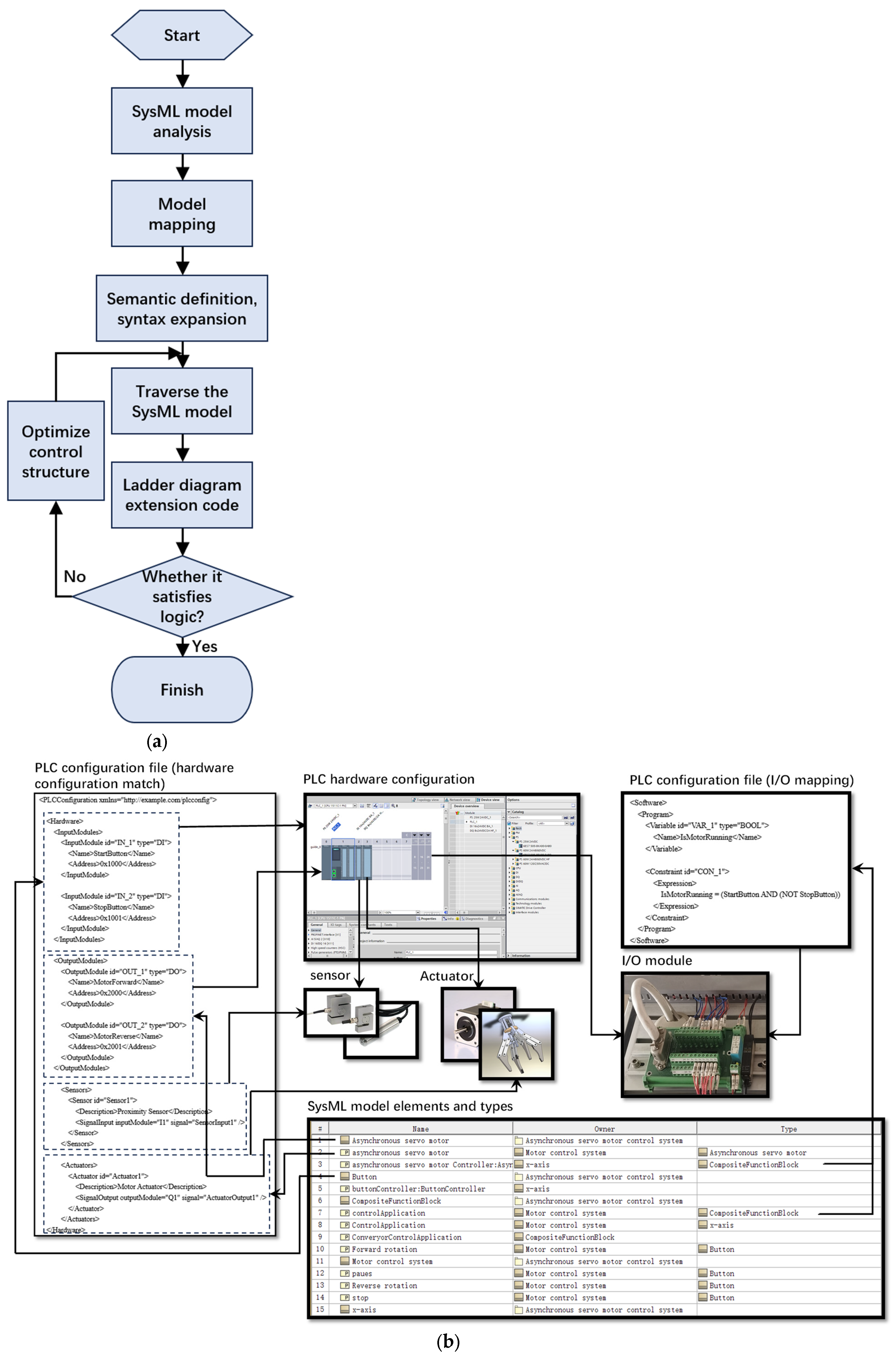
3.1. Automatic Generation of PLC Control Logic Based on System Design Models

The paper introduced a method for the automatic generation of a PLC control logic based on system design modeling, emphasizing the importance of logic architecture in system design. This involves decomposing functionality while considering factors like technology selection, solution subcontracting, and component reuse. The proposed approach starts with a deep analysis of the SysML model, extracting information about modules, parameters, activity diagram, sequence diagram, and state diagram. Key details, especially about modules and parameters, form the basis for hardware and software configuration, defined and processed by PLC configuration files. The system’s control logic is automatically derived from activity diagram, sequence diagram, and state diagram, capturing activities, interactions, and state machines. Introducing ladder diagram extensions graphically represents the logical structure and sequence of the PLC program, extracting simple logic and operations. State machines facilitate mapping complex logic into structured textual code, transforming high-level logic into executable code. Customized relationships between model elements, such as associations, inheritance, and dependencies, are established using a model transformation system to represent connections and dependencies. The final step involves generating the PLC control program automatically through a conversion script that integrates the gathered information into associate input and output signals, ensuring logical consistency and proper interaction. Refer to Figure 1 for an illustration.

3.1.1. System Design Model

To deduce the control logic of a PLC, the most relevant information about the system is its structure and manufacturing process [25]. Considering that various model elements are provided in SysML, the most appropriate one should be selected to express this information. For this reason, the information to be captured in this section is defined as the System Component Model (SCM) and the System Process Model (SPM).
A system component model describes the components of a system, including physical components, software components, logic modules, and others, along with their interrelationships [26]. These elements collaboratively achieve the system’s functionality and behavior. In contrast, the system process model captures dynamic behavior by modeling the execution sequence of operations through a control flow, facilitating the understanding of signal passing between operations [27].
System modeling offers a clear depiction of the system’s structure, composition, relationships, and functions. This clarity aids in comprehending and designing the system’s control logic, ensuring proper operation and coordination of the model.

3.1.2. Association and Mapping of System Design and PLC Control Logic Model Elements

In the integrated design process of electromechanical products, the key to establishing the model transformation method lies in the mapping relationship between the system model and simulation model elements [28].
Firstly, the specific structures of SysML and PLC are analyzed. In SysML, features encompass structural features (attributes like value attributes and component attributes) and behavioral features (activities, interactions, and state machines). The CPU serves as the PLC’s core, responsible for executing programs and processing logical operations. Input modules receive external signals, including sensor signals and key statuses, which are processed by the CPU to trigger control actions. Output modules send signals to external devices based on the CPU’s judgment, realizing control actions. The Siemens S7-200 SMART PLC is used as the control platform, the automatic code generation tool is developed by Python 3.10.11 (Python Software Foundation), and the script writing and debugging are completed in Visual Studio Code 1.83.1 (Microsoft) environment. The script was written and debugged in Visual Studio Code 1.83.1 (Microsoft) environment through Python 3.10.11 (Python Software Foundation) development code automatic generation tool and finally verified by TIA Portal V16 (Siemens) deployment.
A model element comparison is performed to identify elements from the SysML model that are relevant to the PLC control program, including system inputs, outputs, state machines, activities, and specific logic controls, as well as to determine the mapping relationship between the SysML model elements and the PLC programming elements. During the model element comparison and mapping process, make necessary extensions to the SysML model elements, such as logic control extensions, state transition extensions, and attribute extensions, to ensure that the logic controls, state transitions, and events in the SysML are appropriately mapped to piggyback onto the appropriate parts of the PLC control program. The aim is to ensure an appropriate mapping of states, conditions, and operations, as illustrated in Figure 2.

PLC Profile

PLC configuration files are crucial for defining hardware configuration and communication settings during model conversion [29]. Initially, an XML (Extensible Markup Language) file is exported from the SysML model, processed, and extracted using Python [30]. This extracted information guides the development of PLC programs, incorporating control logic and functional requirements. Model-defined information related to PLC hardware aligns with actual PLC devices [31]. I/O port mapping is then applied in the PLC configuration file, defining addresses and mapping relationships for input/output devices. This file maps SysML logical signals in the model to actual PLC input and output signals. Then, assign the tasks and programs in the SysML model to the tasks and programs of the PLC, define the priority of the tasks, scheduling strategy, and other information to ensure that the various functions in the system are executed appropriately, and finally check whether the generated PLC code meets the system requirements through the automated test script, as shown in Figure 3.
The specific process from the SysML model to the automatic generation of the PLC control program is illustrated in Figure 3b, including the mapping relationships between the PLC configuration file, hardware configuration, I/O modules, and the SysML model elements and types. The SysML Model Elements and Types section in the lower left corner shows the individual elements of the SysML model and their types. These elements include asynchronous servo motors, pushbutton controllers, control applications, and so on. Each element is associated with the system and type it belongs to. The PLC Configuration File (Hardware Configuration Matching) section in the upper left corner shows an example of a PLC configuration file that defines the PLC’s hardware configurations. These configurations include details of input modules, output modules, sensors, and actuators. The InputModule and OutputModule define their respective ID, type (DI or DO), name, and address. The Sensor and Actuator configurations describe their descriptive information and signal mapping. The PLC Hardware Configuration in the upper center shows the PLC Hardware Configuration interface, which is configured and managed through the programming software. This interface shows the physical arrangement of the PLC modules and the detailed configuration of each module. Sensors and actuators in the middle of the figure shows pictures of the actual sensors and actuators that will interact with the PLC system as described in the PLC configuration file. The sensors receive external signals and pass them on to the PLC, while the actuators perform the appropriate actions based on the output signals from the PLC. The lower right section shows pictures of the I/O modules that are used to connect the sensors and actuators as well as to process the signal inputs and outputs through the PLC. The upper right section shows the I/O mapping part of the PLC configuration file, including variable definitions and constraints. The variable defines the ID, type, and name, such as the “IsMotorRunning” variable. Constraints define logical expressions that are used to control the logical operations of the PLC, such as “IsMotorRunning = (StartButton AND (NOT StopButton))”. The figure shows how the SysML model can be extended to map to the PLC control program, including mapping logic control, state transitions, and events to the PLC control program. The overall demonstration of the process from the SysML model to the automatic generation of the PLC control program emphasizes the identification of model elements, the establishment of mapping relationships, and the specific implementation of hardware and software configurations.
The process of mapping SysML model elements to PLC control program elements can be described mathematically or through algorithmic insight using formal methods and specific algorithmic steps. A detailed description is given below:
Mathematical representation:
1. SysML model element representation:
Let MSysML be a SysML model containing a set of elements ESysML.
Each element eSysML∈EsysML can be represented by the set of attributes {a1, a2, …, an}.
2. PLC control program element representation:
Let MPLC be a PLC control program model containing a set of elements EPLC.
Each element ePLC∈EPLC can be represented by the set of attributes {b1, b2, …, bn}.
3. Mapping function:
Define a mapping function f:ESysML→EPLC that maps a SysML model element to a corresponding PLC control program element.
The mapping relation can be expressed as f(eSysML) = EPLC, where eSysML and ePLC satisfy specific attribute matching rules.
Algorithm steps (Algorithm 1):
Algorithm 1: SysML-PLC mapping conversion algorithm
1. Initialization:
Initialize the SysML model element set EsysML and the PLC control program element set EPLC.
2. Feature Extraction:
Extract key features {a1, a2, …, an} of SysML model elements.
Extract key features {b1, b2, …, bn} of PLC control program elements.
3. Matching rule definition:
Define a set of matching rules R. Each rule ri∈R denotes the relationship between the attributes of a SysML element and the attributes of a PLC element.
Example rule:
If eSysML is a state machine and contains state transitions, it is mapped to the logical control section in ePLC.
If eSysML is an input interface, it maps to an input module in the ePLC.
4. Mapping process:
For each eSysML ∈ EsysML, apply the matching rule R to find the corresponding ePLC.
The specific steps are as follows:
  for e_sysml in E_sysml.
     for r in R.
       if r.matches(e_sysml).
         e_plc = r.map_to_plc(e_sysml)
         E_plc.add(e_plc)
Example:
Assume that the SysML model contains a button (Button) and a motor (Motor), and the PLC control program contains the corresponding input and output modules.
1. SysML model element:
Button: {type: “Button”, action: “Start”}.
Motor: {type: “Motor”, State: “Running”}.
2. PLC control program elements:
InputModule: {type: “DI”, address: “0x1000”}.
OutputModule: {type: “DO”, address: “0x2000”}.
3. Mapping rules:
Button maps to InputModule.
Motor maps to OutputModule.
4. Mapping process:
Button: {type: “Button”, action: “Start”} -> InputModule: {type: “DI”, address: “0x1000”}.
Motor: {type: “Motor”, State: “Running”} -> OutputModule: {type: “DO”, address: “0x2000”}.
The mapping process from SysML model elements to PLC control program elements can be formalized and algorithmically implemented through the above steps to ensure the accuracy and efficiency of the mapping process.

Ladder Diagram Extension

The ladder diagram extension is introduced to the SysML activity diagram to visually depict the logical structure and sequence of a PLC program. Its role is to translate various elements in the SysML model, such as buttons and motors, into logical components of the ladder diagram. This process generates a ladder diagram representation that aligns with the SysML model [32]. The ladder extension enables the SysML model to articulate the system’s behavior and control logic. Converting the SysML model into a ladder diagram facilitates programming of the control logic into the PLC [33]. Table 1 illustrates the correspondence between some common SysML activity diagram elements and the LAD code.
The process of translating the SysML model into a PLC control program involves using ladder extensions to convert activities and branching logic from the activity diagram to logic elements in the ladder diagram. Initially, a Python script extracts the system structure, components, and control logic from the XML file exported from the system model. Mapping rules from the system model elements to the ladder diagram elements are defined, and the semantics are extended by establishing syntax rules for the ladder diagram extensions. This ensures that the resulting PLC program accurately executes the expected behavior in the model. Next, the SysML model elements are traversed, and those requiring conversion, based on the mapping rules, are identified. The corresponding ladder extension code is then generated using the syntax rules, transforming the activity diagram into a ladder logic structure. Subsequent optimization of the generated code involves assessing whether it aligns with the intended control logic.
The steps and methods of ladder diagram expansion are as follows:
Step One: Activity Mapping
1. Activity identification: Develop rules and templates, define the characteristics of activity diagram elements, and then use scripts to match and identify the different operational processes represented by each activity in the activity diagram.
2. Activity mapping: Design appropriate ladder diagram logic blocks for each activity and use different ladder diagram elements according to the nature of the activity.
Step Two: Control process mapping
1. Sequential control: According to the control flow in the activity diagram, the sequential activities are mapped to the sequential execution in the ladder diagram by connecting logical blocks.
2. Branching and merging: Map the branches (decision points) in the activity diagram and merge them to conditional decisions and connections in the ladder diagram, and use relays, contacts, etc., to implement different paths.
Step Three: Control logic mapping
1. Map branch logic: Map branch logic in the activity diagram, such as IF-ELSE conditions, to conditional blocks in the ladder diagram, and use relays, contacts, etc., to implement conditional judgments. Ensure that branching logic remains semantically consistent during transitions by extending the syntax rules of the ladder diagram. For example, use parallel logic blocks in a ladder diagram to represent parallel branches in an active diagram.
2. Mapping loop logic: If the activity diagram contains loops, map them to loop blocks in the ladder diagram and use timers, counters, etc., to implement different types of loops. Extend the syntax rules of ladder diagram to support the representation of loop logic. Loop logic can be implemented using timers or counters to ensure that the semantics are consistent with the looping behavior in the activity diagram.
Step Four: Input and output mapping
1. Input mapping: Map inputs in the activity diagram to input signals in the ladder diagram, such as buttons, sensors, etc.
2. Output mapping: Map the output in the activity diagram to output signals in the ladder diagram, such as motor, display, etc.
Step Five: Generate a ladder diagram
Based on the above mappings and rules, a ladder diagram is progressively created to include activity, control logic, and input/output mappings extracted from the activity diagram. The ladder diagram can be implemented using logical elements provided in PLC(TIA Portal V16) programming software (such as relays, contacts, and timers). The process is shown in Figure 4.
In order to convert SysML models to PLC control programs and ensure correctness through ladder extensions, the following steps can be taken to optimize the generated code and evaluate its compliance. First, the code is optimized through modularization, which modularizes commonly used logic structures or subroutines to improve code reusability and maintainability. In addition, where possible, parallel processing logic is optimized to improve the responsiveness and efficiency of the system. Second, through simulation testing, the generated ladder code is run in the simulation environment, and virtual I/O modules are used to simulate the behavior of real sensors and actuators to check the response and performance of the system under different conditions. At the same time, coverage analysis is performed using a code coverage tool to ensure that all logic branches and state transitions are tested. To further improve efficiency, partial automation of the analysis can be performed in combination with scripts and tools. For example, use Python scripts to automatically generate a ladder code and combine it with model checking and simulation tools for semi-automated verification. These measures will ensure that the generated code is efficient, accurate, and conforms to the intended control logic.
Figure 4b shows the mapping details from the SysML activity diagram to the ladder diagram. Each activity in the activity diagram is mapped to the corresponding logic block in the ladder diagram, the control flow is mapped to the relay logic, the control logic is mapped to the logic operators in the ladder diagram, and the input and output elements are mapped to the I/O modules in the ladder diagram. The final generated ladder diagram demonstrates the logic of forward, backward, pause, stop, etc. These steps ensure that the conversion process from the SysML model to the PLC control program is rigorous and accurate, and the correct execution of the control logic is achieved through the definition of the mapping rules and syntax expansion. Optimization of the control structure and simulation tests further improve the reliability and validity of the code.
Activity mapping: Each activity in the activity diagram is mapped to the corresponding logic block in the ladder diagram. For example, “Forward rotation” and “Reverse rotation” are mapped to the forward and reverse logic in the ladder diagram.
Control flow mapping: The control flow in the activity diagram is mapped to the relay logic in the ladder diagram. For example, “Forward rotation Pressed” and “Reverse rotation Pressed” correspond to button states in the ladder diagram.
Control logic mapping: The control logic in the active diagram is mapped to the logic operators in the ladder diagram. For example, empty function block, open branch, normally open contact, etc.
Input/Output mapping: The input and output elements in the active diagram are mapped to I/O modules in the ladder diagram. For example, the input and output signals of sensors and actuators are mapped to specific I/O addresses in the ladder diagram.
Generated Ladder Diagram: The final generated ladder diagram shows the result of the entire conversion process, including forward, backward, pause, and stop logic.

State Diagram to Structured Text Extension

We use the State Diagram to ST extension to convert the state machine diagram in SysML to a ST representation in the PLC programming language through model conversion, so that the state transitions and behaviors defined in SysML can be translated directly into PLC control logic. We extract the text label of each state node through a custom script and use predefined text templates to integrate the text information of each state into a text block of structured state names, descriptions, and possible triggering events. Templates define the structure and content of text blocks.
Steps and methods for extending state diagram to ST:
Step One: State transition condition mapping
1. State mapping: Determine the ST block that corresponds to each state in the state machine diagram.
2. State transition mapping: Map the state transitions in the state machine diagram to conditional judgments and control flow statements in ST. These statements determine whether to execute a state transition.
Step Two: State action mapping
1. State entry action mapping: Map the state entry action in the state machine diagram to the state entry operation in the ST.
2. State exit action mapping: Map states with exit actions in the state machine diagram to operations when the state exits in ST.
Step Three: State control logic mapping
Each state in the state machine diagram is mapped to conditional judgments, loops, and operations in ST based on the control logic within the state.
Step Four: System control mapping
According to the state and transition conditions controlled by the SysML model, the control logic is mapped to conditional judgments and operations in ST.
Step Five: ST generation
Based on the above mappings and rules, the ST code can be incrementally generated to contain the mapping of states, state transitions, control logic, and button operations extracted from the SysML state machine diagram. When generating the ST code, use the syntax and operators provided by the PLC programming software.
As shown in Figure 5. The PLC code example on the right shows a typical state machine logic including the following state and control logic:
Method Definition:
METHOD ControlActuator (State: BOOL): defines a method that controls the state of the actuator based on the state (Boolean value) passed in.
CASE statement:
CASE SystemState OF: defines a state selection structure that executes different logic depending on the current state of the system.
Idle state (Idle):
In the Idle state, if the Start button is pressed, the system enters the Running state and starts the system.
Running:
In the Running state, if the Stop button is pressed, the system stops running.
At the same time, the status of the sensors is monitored. If the sensor value changes and the detection result is abnormal, the system enters the Error state and shuts down the actuator.
Error:
In the Error state, if the Reset button is pressed, the system resets to the Idle state.
Variable generation method: In PLC programming, all variables are defined following the PLC standard format. Specifically, all variable declarations are located between the VAR and END_VAR of the program. This ensures that the scope of the variables in the program is properly controlled. In this way, we can clearly define input, output, and local variables as well as adjust the variable types to the needs of the program. For example, the State variable, which controls the actuator and is used to indicate the current state of the system, is defined as a Boolean type (BOOL). In the program, this variable is defined as follows:
VAR
    State: BOOL;//Define a Boolean variable State
END_VAR
This part of the code is responsible for defining all necessary input, output, and local variables, and adjusting them accordingly to the needs of the control logic in the real world to ensure that the role and scope of each variable is clear.
“System State” enumeration type: With respect to “System State”, it is an enumeration type used to represent the different operating states of the system. Enumeration types are more efficient and readable than string arrays and are more maintainable in programming. Each enumeration value corresponds to a specific state of the system, and enumeration types help us to manage system states such as Idle, Running, and Error in a concise and efficient way. In the code, the SystemState enumeration type is defined as follows:
TYPE SystemState: (Idle, Running, Error);//Define SystemState as an enumeration type
With this enumeration type definition, it is clear that we can determine and toggle the state of the system in the control logic. This approach avoids the complexity of using an array of strings, making the program more concise and easier to understand, and improving the efficiency of code execution. In the CASE statement, we can select different program branches based on the SystemState enumeration type to perform the corresponding logical operations, such as those for the Idle, Running, and Error states shown in the figure. The use of this enumeration type makes the state management of the system clearer and avoids the confusion and performance problems that can be caused by arrays of strings.

3.1.3. Control Program Automatically Generated

Converting a SysML model into an actual PLC control program code is a complex process. This article employed a method that combines PLC configuration files, ladder diagram extensions, and state diagram to ST extensions for this conversion. Initially, the SysML model is analyzed to comprehend all aspects of the system, including motors, buttons, and state transitions. Information from the model is then extracted and mapped to PLC configuration files, ladder diagram, and state diagram. Using the PLC configuration tool, a file is created to encompass the hardware configuration, specifying input and output modules, sensors, and actuators. The signals, inputs, and outputs in the configuration file align with the states and events in the SysML model. The ladder diagram depicts push-button operations and simple logic, converting SysML model operations into logic elements like relays, timers, and bit indicators. A state diagram is used to represent the state and state transitions of the system based on the state and state transition conditions in the SysML model, ensuring that the states in the state diagram correspond to the signals and inputs and outputs in the PLC configuration file. For intricate logic, ST extensions translate high-level SysML model logic into ST code. The integrated control logic from the PLC configuration file, ladder extensions, state diagram, and ST is mapped to input and output signals, ensuring consistency and proper interaction. The PLC control program generated through automatic conversion is then loaded into the actual PLC device. Optimization based on test results is performed to ensure system reliability and performance, as depicted in Figure 6.

3.2. Implementation and Case Studies

This article presents a prototype system developed using No Magic’s Cameo Systems Modeler Demo (Version 19.0) and Siemens’ TIA Portal V16 for automated integration, optimization, and generation of PLC control programs during the system design modeling process [34]. The section outlines the steps involved, using a handling manipulator as a verification example. It begins by showcasing the manipulator’s functionality and the corresponding system model. The model is then extended appropriately with activity diagram, state diagram, and main components (blocks) defining the system, along with their relationships. Subsequently, the code from PLC configuration files, ladder diagram, state diagram, and ST is integrated to ensure logical consistency and proper interaction. The integrated code is loaded into the actual PLC device. Finally, system operation is simulated to verify the PLC control program’s functionality and debugged to address any issues or errors.

3.2.1. Construction of Functional and System Models

The manipulator’s primary role is to retrieve the processed workpiece from the conveyor belt and transport it to a specified location for subsequent assembly. The control system comprises key components: the manipulator, large and small arms, a motor, a gripper, and control buttons. These components are instantiated and integrated into the overall system, encompassing telescoping functions of the arms, gripping and releasing actions of the mechanical grippers, arm rotation driven by motors, and overall system control functions such as start, pause, and stop.
To realize the functions of the manipulator, the whole system is managed by a controller called “Gripper Control Application”. The controller consists of five sub-controllers, namely the gripper controller, the large arm controller, the small arm controller, the motor controller, and the button controller. These software components are modeled using function blocks to accomplish the various control tasks of the system. The relationship between system components and software, shown in Figure 7, ensures that each component can be properly controlled and managed to work together to accomplish the various operations of the manipulator.

3.2.2. System Model Conversion and Analysis

The overall framework for automatic control program generation involves a custom model conversion system that imports and parses XML files generated by the SysML modeling tool. This system extracts model information, automatically assigning elements from the handling manipulator’s SysML model to PLC configuration files based on predefined rules, and associates relevant elements with PLC profiles, ladder diagram extensions, and state diagram. These assignments are designed based on the types and attributes of the model elements. The process further includes creating ladder diagram extensions based on element relationships in the model as well as automatically generating state diagram and ST extension codes based on defined state and transition relationships. This encompasses defining states, conditional transitions, event triggering, and more. Next, the system generates actual use cases for the handling robot, exporting them to XML file format. The information from these generated use case files is seamlessly integrated into the PLC programming environment, resulting in the corresponding control logic. The generated PLC program is then loaded into the PLC virtual simulator via TIA Portal for testing, as illustrated in Figure 8.
In Figure 9, depicting the conversion of the manipulator system model into a PLC control program, the process is delineated across seven areas in the activity diagram. Each area corresponds to a component instance, denoting its name and type. For instance, the initial area pertains to the Start component of Button type, activated by the Start Pressed signal from the Accept Signal action. This signal signifies the operator pressing the Start button, initiating the system through a Trigger Process action that sends a start signal to the motor. Subsequently, the motor responds with a Forward rotation action. Upon pressing the Pause button (indicated by the Pause Pressed signal), the system enters a Wait state, as denoted by the Wait action. Pressing the Stop button during system operation or while waiting (as indicated by the Stop Pressed signal) triggers the Stop signal, halting the transport process with the Stop action. The Merge node, presented as a diamond, consolidates control streams from Forward rotation and Wait actions into a unified stream directed towards the Stop Pressed operation. Once the system halts successfully, the Stop signal is transmitted, concluding the entire process.
The automatically generated control program aligns with the activity diagram of the SysML model. It exhibits the following control logic: Q0.1 manages the motor’s forward rotation, Q0.3 handles the reverse rotation, Q0.4 and Q0.5 regulate the large arm’s expansion and contraction, Q0.2 and Q0.6 control the small arm’s movement, and Q0.0 oversees the gripping and mounting of the workpiece using mechanical jaws. Upon pressing the Start button, the PLC CPU sequentially executes the user program line by line, starting from the initial instruction. During the first scan, the normally closed contact of I0.4 is energized, initiating the first scanning cycle. Consequently, Q0.1 coil activates, initiating positive motor rotation and manipulator movement. Further steps involve the extension of the large arm (Q0.4), extension of the small arm (Q0.2), gripping of the workpiece (Q0.0), and subsequent motor reversal for transporting the workpiece to the mounting position. After mounting, additional actions include the retraction of the small arm (Q0.6) and large arm (Q0.5). The system then initiates a new cycle, repeating the described steps.
After the control program is generated, engineers can import it into the built simulation model for debugging and simulation or to further refine the design in the SysML modeling environment, which is called the Cameo Systems Modeler Demo.
In automated production line control, SysML modeling of electromechanical systems can clearly define the functions, interactions, and control logic of each station, laying the foundation for the automatic generation of PLC programs. Taking a production line containing modules of material supply, processing, handling, installation, and sorting as an example, the test shows that the actual sequence of actions is completely consistent with the logic of the model, and that the material supply, processing, transmission, and other links can be executed accurately. The validation results confirm that the model and the actual behavior are highly consistent, the control program is reliable, and the algorithm optimization is effective, which successfully realizes the accurate transition from the model to the actual production and provides a strong support for the design of industrial automation production line.
After completing the development and debugging of the PLC program, the experimental data before and after the optimization are compared and analyzed in order to verify the impact of the optimization algorithm on the operating efficiency of the PLC control program. As shown in Figure 10, compared with the traditional hand-written program, the optimized program achieves a breakthrough improvement in the dimension of running time, in which the reduction of the running time of the complex stations such as the handling station and the installation station is particularly significant (up to 26% reduction). This performance improvement is mainly due to the synergy between the model-driven automated code generation mechanism and the hybrid optimization algorithm, which effectively eliminates the redundant operations and inefficient paths present in manual programming.
The optimization effect is further validated by the memory footprint comparison results shown in Figure 11, where the memory footprint of the optimized program is reduced by 23% on average, and even reaches a reduction of more than 40% at critical sites. This significant improvement in resource utilization stems from two aspects: first, the intermediate variable storage is streamlined by the data flow optimization technique; second, the path optimization algorithm reconstructs the execution sequence of the control logic. Experimental data show that the optimized program not only improves the instruction execution efficiency (IPC increased by 15%) but also reduces the cache miss rate (reduced by 30%), realizing the synergistic optimization of computing and storage resources.
Combining the analysis results of the two key indicators, it can be concluded that the model transformation and optimization method proposed in this paper makes PLC programs gain significant improvement in both time and space efficiency dimensions, and the optimized auto-generated programs have significant advantages in scalability. Through the modular design architecture, only local adjustments are required for system expansion, avoiding the global reconfiguration problem common in manual programming. Compared to traditional methods, the auto-generated program reduces the maintenance cost of system expansion while maintaining the performance advantage, and this improvement directly translates into an increase in the overall efficiency of the production line. Although the automatically generated code can meet the basic control requirements, it still needs to be manually optimized when dealing with complex logic, high real-time tasks, or resource-constrained scenarios. For example, when the timing deviation is more than ±10 ms, the success rate of fault recovery is less than 99.9%, or the CPU load is persistently higher than 80%, it is necessary to further improve the performance by adjusting the nested logic, optimizing interrupt processing, or streamlining the redundant code. While maintaining the advantages of automation generation, this method ensures highly reliable operation in complex industrial environments through targeted optimization, providing an efficient solution for industrial automation systems.
This solution has cross-platform versatility in architectural design, and its model-driven approach based on SysML is able to abstractly describe the core elements of the control logic, realizing decoupling from specific PLC implementation technologies. However, in actual engineering applications, due to the different PLC vendors in the hardware architecture and software development environment, there are certain vendor-dependent characteristics mainly reflected in three aspects: first, the differences in memory addressing mode; second, the differences in the data type system, including the definition of the bit-width of the basic data types and composite type of storage; finally, the specificity of the development environment, such as in the project file structure and programming syntax. When it is necessary to adapt to a new PLC platform, fast adaptation is achieved through a modularized library of conversion rules, and the main modifications include:
  • Updating the address mapping rules to establish the conversion relationship from abstract variables to concrete hardware addresses;
  • Adjusting the data type system to ensure that the data type definitions in the model are compatible with the target platform;
  • Reconfiguring the code generation templates to output the source code that conforms to the syntax specification of the target platform.

4. Discussion

With the widespread adoption of model-based systems engineering development methods in the realm of electromechanical system design, there is a growing inclination towards enhancing the systematic and integrated nature of electromechanical system design methodologies [35]. This paper introduced an innovative approach to automatically generate control programs for PLCs using SysML system design models. The entire process is implemented within the SysML modeling platform, Cameo Systems Modeler Demo, and Siemens’ TIA Portal V16, further extended by custom-developed plug-ins [36]. The core concept of this method revolves around the automatic integration, optimization, and generation of PLC control programs during the system design modeling phase. By encapsulating the system design within SysML models, control programs for specific areas can be directly generated from these models, streamlining the subsequent development of targeted control domains. This approach signifies a paradigm shift in mechatronic system design, harmonizing system engineering with control programming. This integration not only enhances efficiency and reduces risk but is also anticipated to play a pivotal role in the future of automation.
The main contributions are summarized as follows:
  • This study presented a method aimed at automating the conversion of SysML models into PLC control programs. The objective was to enhance the systematization and integration of electromechanical system design methods by seamlessly incorporating SysML system design models into the PLC control program generation process.
  • This study extended the SysML modeling platform and PLC programming environment through the development of plug-ins, fostering enhanced integration and collaboration. This expansion paves the way for future integration possibilities and broader development.
  • This study employed a model-driven development method that integrated system design modeling with control program generation. This approach enhances the maintainability of the system design as any changes made to the model are automatically reflected in the generated control program.
Future work prospects:
  • In this study, only one modeling platform was utilized. Consideration of additional standards and specifications in the future could enhance integration and interaction among diverse modeling tools and PLC programming environments. Furthermore, the development of more robust model validation and analysis tools is recommended to facilitate the early detection of potential issues within the model.
  • The current methodology relies solely on a single system model. For enhanced flexibility in the manufacturing process, it is imperative to consider how relationships and mappings between different models can be seamlessly integrated to ensure system-level consistency.

Author Contributions

All authors contributed to the study conception and design. The first draft of the manuscript was written by B.L. and all authors commented on previous versions of the manuscript. All authors have read and agreed to the published version of the manuscript.

Funding

This work was supported by the Open Fund of the State Key Laboratory of Digital Manufacturing Equipment and Technology of China (Grant number: DMETKF2022015).

Data Availability Statement

Data are contained within the article.

Acknowledgments

I am grateful to the relevant funds and programs that funded this study for their financial and material support, which enabled me to carry out my work successfully. Thanks to all the organizations or individuals who provided material and equipment support during the experiments; it is due to their help that I was able to carry out the research and experiments successfully.

Conflicts of Interest

The authors declare no conflicts of interest.

Abbreviations

The following abbreviations are used in this manuscript:
PLCProgrammable Logic Controller
STStructured Text
SysMLSystem Modeling Language
UMLUnified Modeling Language
SCMSystem Component Model
SPMSystem Process Model

References

  1. Wilch, J.; Fischer, J.; Langer, N.; Felger, M.; Bengel, M.; Vogel-Heuser, B. Towards automatic generation of functionality semantics to improve PLC software modularization. at-Automatisierungstechnik 2022, 70, 181–191. [Google Scholar] [CrossRef]
  2. Hossain, N.U.I.; Lutfi, M.; Ahmed, I.; Akundi, A.; Cobb, D. Modeling and Analysis of Unmanned Aerial Vehicle System Leveraging Systems Modeling Language (SysML). Systems 2022, 10, 264. [Google Scholar] [CrossRef]
  3. Songtao, F.; Haisheng, H.A.O. Research on spacecraft digital twin system technology based on model operating system. Inf. Commun. Technol. Policy 2021, 47, 8. [Google Scholar]
  4. Vermuyten, E.; Meert, P.; Wolfs, V.; Willems, P. Combining model predictive control with a reduced genetic algorithm for real-time flood control. J. Water Resour. Plan. Manag. 2018, 144, 04017083. [Google Scholar] [CrossRef]
  5. Brecher, C.; Nittinger, J.A.; Karlberger, A. Model-based control of a handling system with SysML. Procedia Comput. Sci. 2013, 16, 197–205. [Google Scholar] [CrossRef]
  6. Schütz, D.; Obermeier, M.; Vogel-Heuser, B. SysML-Based Approach for Automation Software Development–Explorative Usability Evaluation of the Provided Notation. In Design, User Experience, and Usability. Web, Mobile, and Product Design, Proceedings of the Second International Conference, DUXU 2013, Held as Part of HCI International 2013, Las Vegas, NV, USA, 21–26 July 2013; Proceedings, Part IV 2; Springer: Berlin/Heidelberg, Germany, 2013; pp. 568–574. [Google Scholar]
  7. Vogel-Heuser, B.; Schütz, D.; Frank, T.; Legat, C. Model-driven engineering of manufacturing automation software projects—A SysML-based approach. Mechatronics 2014, 24, 883–897. [Google Scholar] [CrossRef]
  8. Sýkora, T.; Husák, M.; Baštán, O.; Benešl, T. Automatic generation of a PLC controller based on a control system-identified model. J. Electr. Eng. 2021, 72, 78–88. [Google Scholar] [CrossRef]
  9. Krupa, P.; Limon, D.; Alamo, T. Implementation of model predictive control in programmable logic controllers. IEEE Trans. Control Syst. Technol. 2020, 29, 1117–1130. [Google Scholar] [CrossRef]
  10. Wolny, S.; Mazak, A.; Carpella, C.; Geist, V.; Wimmer, M. Thirteen years of SysML: A systematic mapping study. Softw. Syst. Model. 2020, 19, 111–169. [Google Scholar] [CrossRef]
  11. Koziolek, H.; Burger, A.; Platenius-Mohr, M.; Jetley, R. A classification framework for automated control code generation in industrial automation. J. Syst. Softw. 2020, 166, 110575. [Google Scholar] [CrossRef]
  12. Fischer, J.; Vogel-Heuser, B.; Friedrich, D. Configuration of PLC software for automated warehouses based on reusable components-an industrial case study. In Proceedings of the 2015 IEEE 20th Conference on Emerging Technologies & Factory Automation (ETFA), Luxembourg, 8–11 September 2015; IEEE: Piscataway, NJ, USA, 2015. [Google Scholar]
  13. Han, K.H. Object-oriented modeling, simulation and automatic generation of PLC ladder logic. In Programmable Logic Controller; IntechOpen: London, UK, 2010. [Google Scholar]
  14. Zyubin, V.E.; Rozov, A.S.; Anureev, I.S.; Garanina, N.O.; Vyatkin, V. poST: A process-oriented extension of the IEC 61131-3 structured text language. IEEE Access 2022, 10, 35238–35250. [Google Scholar] [CrossRef]
  15. An, Y.; Qin, F.-W.; Chen, B.; Simon, R.; Wu, H. OntoPLC: Semantic model of PLC programs for code exchange and software reuse. IEEE Trans. Ind. Inform. 2020, 17, 1702–1711. [Google Scholar] [CrossRef]
  16. Niang, M.; Riera, B.; Philippot, A.; Zaytoon, J.; Gellot, F.; Coupat, R. A methodology for automatic generation, formal verification and implementation of safe PLC programs for power supply equipment of the electric lines of railway control systems. Comput. Ind. 2020, 123, 103328. [Google Scholar] [CrossRef]
  17. Leserf, P.; de Saqui-Sannes, P.; Hugues, J. Trade-off analysis for SysML models using decision points and CSPs. Softw. Syst. Model. 2019, 18, 3265–3281. [Google Scholar] [CrossRef]
  18. Cao, Y.; Xu, J.; Liu, Y.; Ye, X.; Zhao, J. Automated generation of control logic from system design based on SysML and the IEC 61499 Function Block. Proc. Inst. Mech. Eng. Part B J. Eng. Manuf. 2019, 233, 2547–2565. [Google Scholar] [CrossRef]
  19. Blagojević, V.; Ranđelović, S.; Nikolić, V.; Dudić, S. Automatic Generation of the PLC programs for the sequential control of pneumatic actuators. Facta Univ. Ser. Mech. Eng. 2019, 17, 405–414. [Google Scholar] [CrossRef]
  20. Jamro, M. Automatic generation of implementation in SysML-based model-driven development for IEC 61131-3 control software. In Proceedings of the 2014 19th International Conference on Methods and Models in Automation and Robotics (mmar), Miedzyzdroje, Poland, 2–5 September 2014; IEEE: Piscataway, NJ, USA, 2014; pp. 468–473. [Google Scholar]
  21. Schütz, D.; Legat, C.; Vogel-Heuser, B. MDE of manufacturing automation software—Integrating SysML and standard development tools. In Proceedings of the 2014 12th IEEE International Conference on Industrial Informatics (INDIN), Porto Alegre, Brazil, 27–30 July 2014; IEEE: Piscataway, NJ, USA, 2014; pp. 267–273. [Google Scholar]
  22. Fan, H.; Liu, Y.; Liu, D.; Ye, X. Automated generation of the computer-aided design model from the system structure for mechanical systems based on systems modeling language. Proc. Inst. Mech. Eng. Part B J. Eng. Manuf. 2016, 230, 883–908. [Google Scholar] [CrossRef]
  23. Thramboulidis, K. A cyber–physical system-based approach for industrial automation systems. Comput. Ind. 2015, 72, 92–102. [Google Scholar] [CrossRef]
  24. Mhenni, F.; Choley, J.Y.; Penas, O.; Plateaux, R.; Hammadi, M. A SysML-based methodology for mechatronic systems architectural design. Adv. Eng. Inform. 2014, 28, 218–231. [Google Scholar] [CrossRef]
  25. Barbieri, G.; Kernschmidt, K.; Fantuzzi, C.; Vogel-Heuser, B. A SysML based design pattern for the high-level development of mechatronic systems to enhance re-usability. IFAC Proc. Vol. 2014, 47, 3431–3437. [Google Scholar] [CrossRef]
  26. Weilkiens, T. Systems Engineering with SysML/UML: Modeling, Analysis, Design; Elsevier: Amsterdam, The Netherlands, 2011. [Google Scholar]
  27. Cao, Y.; Liu, Y.; Paredis, C.J.J. System-level model integration of design and simulation for mechatronic systems based on SysML. Mechatronics 2011, 21, 1063–1075. [Google Scholar] [CrossRef]
  28. Batchkova, I.; Antonova, I. Improving the software development life cycle in process control using UML/SysML. IFAC Proc. Vol. 2011, 44, 14133–14138. [Google Scholar] [CrossRef]
  29. Ramos, A.L.; Ferreira, J.V.; Barceló, J. Model-based systems engineering: An emerging approach for modern systems. IEEE Trans. Syst. Man Cybern. Part C (Appl. Rev.) 2011, 42, 101–111. [Google Scholar] [CrossRef]
  30. Han, K.H.; Park, J.W. UML-based PLC Ladder Logic Design and Automatic Generation of Ladder Code. Korean J. Comput. Des. Eng. 2009, 14, 50–59. [Google Scholar]
  31. Hoffmann, H.P. Harmony/SE: A SysML based systems engineering process. In Proceedings of the Innovation 2008. France: Telelogic User Group Conference, Paris, France, 9–11 December 2008; pp. 1–25. [Google Scholar]
  32. Hirsch, M.; Missal, D.; Hanisch, H.M. Design and verification of distributed industrial manufacturing control systems. In Proceedings of the 2008 34th Annual Conference of IEEE Industrial Electronics, Orlando, FL, USA, 10–13 November 2008; IEEE: Piscataway, NJ, USA, 2008; pp. 152–157. [Google Scholar]
  33. Liu, S.; Young, R.I.M. An exploration of key information models and their relationships in global manufacturing decision support. Proc. Inst. Mech. Eng. Part B J. Eng. Manuf. 2007, 221, 711–724. [Google Scholar] [CrossRef]
  34. Zhang, W.; Halang, W.A.; Diedrich, C. Specification of function block applications with UML. In Proceedings of the 2005 IEEE International Conference on Robotics and Automation, Barcelona, Spain, 18–22 April 2005; IEEE: Piscataway, NJ, USA, 2005; pp. 4002–4007. [Google Scholar]
  35. Burmester, S.; Giese, H.; Tichy, M. Model-driven development of reconfigurable mechatronic systems with mechatronic UML. In European Workshop on Model Driven Architecture; Springer: Berlin/Heidelberg, Germany, 2003; pp. 47–61. [Google Scholar]
  36. Friedenthal, S.; Meilich, A.; Lykins, H. Adapting UML for an Object Oriented Systems Engineering Method (OOSEM). In Proceedings of the INCOSE International Symposium, Minneapolis, MN, USA, 16–20 July 2000; INCOSE: San Diego, CA, USA, 2000. [Google Scholar]
Figure 1. Automatic PLC control logic generation method based on system design modeling.
Actuators 14 00201 g001
Figure 2. Model analysis and mapping.
Actuators 14 00201 g002
Figure 3. PLC configuration file conversion: (a) flow chart, (b) related hardware configuration, and mapping.
Actuators 14 00201 g003
Figure 4. Ladder diagram extension conversion: (a) flow chart, (b) mapping of operations, and simple logic in the model to control logic and its elements in the ladder diagram.
Actuators 14 00201 g004
Figure 5. Converting complex logic in system models to ST code.
Actuators 14 00201 g005
Figure 6. Steps for converting the SysML model into a PLC control program.
Actuators 14 00201 g006
Figure 7. SCM of the manipulator system: (a) system structure, (b) control components, and (c) distribution between system and control components.
Actuators 14 00201 g007
Figure 8. Application of synchronization conversion framework of the handling robot system model.
Actuators 14 00201 g008
Figure 9. The handling robot system model is converted into a PLC control program.
Actuators 14 00201 g009
Figure 10. Comparison of PLC control program running time before and after optimization.
Actuators 14 00201 g010
Figure 11. Comparison of memory consumption of PLC control program before and after optimization.
Actuators 14 00201 g011
Table 1. Mapping relationship between activity diagram modules and elements in a SysML and PLC ladder diagram.
SyaML Activity Diagram ElementsCorresponding PLC Ladder Diagram CodeelementsMapping Relations
Control Flow-No mapping is required, indicating control flow
Action-No mapping is required, representing activities or actions
Decision Node-No mapping is required, representing decision nodes
Merge Node-No mapping is required, indicating merging nodes
Input PinInput module or variableInput pin represents input signal or data
Output PinOutput module or variableOutput pin represents output signal or data
Call Behavior ActionCall PLC subroutineRepresents calling the corresponding subroutine or function in the PLC
Constraint-No mapping is required, expressing constraints
Activity Partition-No mapping is required, representing active partition or swim lane
Fork Node-No mapping is required, indicating parallel processing
Join Node-No mapping is required, indicating merge processing
Decision Input Flowconditional logicRepresents conditional logic and performs different actions based on conditional judgment.
Object Flowdata transmissionRepresents data transfer, used to connect different activities and actions
Disclaimer/Publisher’s Note: The statements, opinions and data contained in all publications are solely those of the individual author(s) and contributor(s) and not of MDPI and/or the editor(s). MDPI and/or the editor(s) disclaim responsibility for any injury to people or property resulting from any ideas, methods, instructions or products referred to in the content.

