Article

Design and Comparative Analysis of a Retrofitted Liquid Cooling System for High-Power Actuators

Cockrell School of Engineering, University of Texas at Austin, 301 E Dean Keeton St, Austin,TX 78712, USA
*
Author to whom correspondence should be addressed.
Actuators 2015, 4(3), 182-202; https://doi.org/10.3390/act4030182
Submission received: 1 July 2015 / Revised: 27 July 2015 / Accepted: 10 August 2015 / Published: 13 August 2015

Abstract

:
This paper presents an in-depth system-level experimental analysis comparing air-cooled and liquid-cooled commercial off-the-shelf (COTS) electric motors. Typically, liquid-cooled electric motors are reserved for large, expensive, high-end applications where the design of the motor’s electromagnetic components are closely coupled to its cooling system. By applying liquid cooling to a pre-existing motor design, this work helps bring the performance advantages of liquid cooling to smaller scale and lower cost applications. Prior work in this area gives little insight to designers of such systems. Conversely, this work aims to improve the understanding of liquid-cooled COTS motors by reporting empirically-observed factors of improvement for motor current, torque, output power and system efficiency. These measurements are obtained using a new liquid-cooled motor housing design that improves the ease of maintenance and component reuse compared to existing work. It is confirmed that datasheet motor thermal properties may serve as a reasonable guide for anticipating continuous torque performance, but may over-specify continuous power output. For the motor used in this test, continuous torque output is increased by a factor of 2.58, matching to within 9% of expected datasheet values. Continuous power output is increased by a factor of two with only 2.2% reduced efficiency compared to air-cooling.

Graphical Abstract

1. Introduction

Conventional applications in the robotics and transportation industries have gravitated towards electric motors due to their high operating efficiency (often above 90%) and their ubiquitous, low-cost and miniaturized embedded motion controllers. While these benefits often outweigh the shortcomings of electric motors compared to other actuation technologies, new applications in robotics and related fields require improvement over the current state-of-the-art. Life-sized autonomous humanoid robots [1], rehabilitation exoskeletons [2] and electric vehicles [3] are just a few examples of current technology development that can directly benefit from electric motors that are less expensive, yet more torque- and power-dense.
Consider an example of current actuation technology limitations. The maximum continuous torque per unit mass for electric motors is currently limited to around 6 Nm/kg given current rare-earth magnets [4]. As a point of comparison, hydraulic actuators achieve torque densities of 90+ Nm/kg, depending on operating conditions [4]. By a torque-density metric, hydraulics performs very well. However, compared to the aforementioned 90% efficiency of electric motors, hydraulic actuation systems perform rather poorly, achieving 14% in one study [5]. Given such limitations, the demands on modern actuators require improvements beyond the current state of the art [6]. Envisioned robotic applications, such as the helpful humanoid house assistant or the disaster robotic first-responder, provide contradicting requirements: torque/mass, power/mass and efficiency are simultaneously required.
While an ambitious goal, incremental steps towards this vision may be realized leveraging existing technology. Liquid cooling of electric motors is one such technology that is commonly used today in a wide range of electric vehicles. These motors span the range from small in-wheel motors for automobiles [3,7,8], to massive megawatt motors for ocean-going ships [9] and everything in between [10,11,12]. The primary benefit of liquid cooling is that heat generated from Ohmic loss can be quickly removed from the system with convection, thus allowing larger continuous current, torque and power output. Additionally, designers of these vehicles are afforded flexibility in the location of the cooling components. In automobiles, for example, this advantage is leveraged in placing the radiator at the front of the vehicle, where it is most likely to encounter cool, pressurized air.
Phase-changing cooling methods, such as heat pipes, capillary-pumped loops and two-phase mechanically-pumped loops provide another option for heat dissipation. Their primary advantage, relative to single-phase liquid cooling, is improved mass effectiveness due to the latent heat of most fluids being at least an order of magnitude greater than their sensible heat [13]. General disadvantages include increased complexity and cost compared to single-phase systems, inflexibility in system layout, potential dependence on gravity and the common use of toxic working fluids, such as ammonia, ethanol and methanol [13]. For these reasons, there has been little work in applying phase changing cooling to electric motors, although a small number of disclosures on such technology have been recently submitted and may prove a viable option in the future [14].
Compared to the transportation industry, single-phase liquid cooling applied to robotic applications is less explored. Existing work can be largely grouped into two distinct categories, each benefiting from the increased continuous torque production. The first category applies liquid cooling to direct drive robotic joints [15,16,17,18]. Drivetrains introduce cost, complexity, additional points of failure and can significantly reduce system efficiency (beyond 50% in some cases [19]). Additional drawbacks include backlash, compliance, and several forms of friction. These factors negatively affect the mechanical durability, energetics and controllability of the robotic system. By removing the drivetrain and directly driving a robotic joint with a motor, most of these issues are reduced or removed completely. At the same time, direct drive robots are much more sensitive to motor torque ripple and possess greatly reduced torque/mass compared to highly geared motors [4]. By liquid cooling a direct drive motor, this torque/mass drawback is reduced. In one study, the continuous torque improved by a factor of six when liquid cooling was applied, resulting in a overall torque/mass of 15 Nm/kg [4,18]. Unfortunately, such motors require a completely custom design and many years of iterative development to obtain a reliable device. This development cycle sets an unrealistically high bar for new adopters of the technology.
The second existing category in robotics uses the combined effects of liquid cooling and a highly geared drivetrain to sustain large continuous joint torques with minimal system mass [20,21,22]. Unlike the large and expensive motors used in the transportation industry or the complex and custom-made direct drive motors, motors intended for geared applications are commercially-available off-the-shelf (COTS), making them ubiquitous and relatively inexpensive. While this type of motor is rarely designed for use with liquid cooling, it is often designed to minimize thermal resistance to surrounding air. By applying liquid cooling, its continuous current can be increased, but rarely to the levels of more expensive or customized liquid-cooled motors. So far, this class of liquid-cooled COTS motors most directly benefits humanoid robots, whose leg joints must support their weight along with the weight of the upper torso and any additional payload [20,21,22]. While demonstrably effective [23], this actuation approach is relatively new and has not been extensively studied or characterized in prior work. For example, in [20], theoretically-expected improvement factors for continuous current are derived, but are never validated empirically.
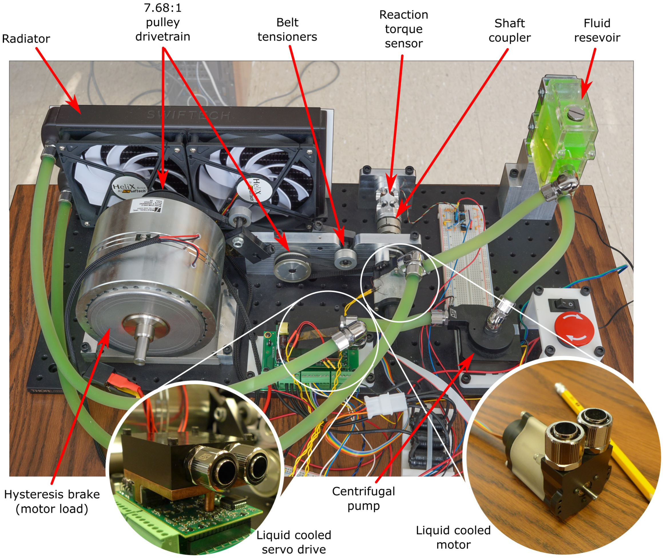
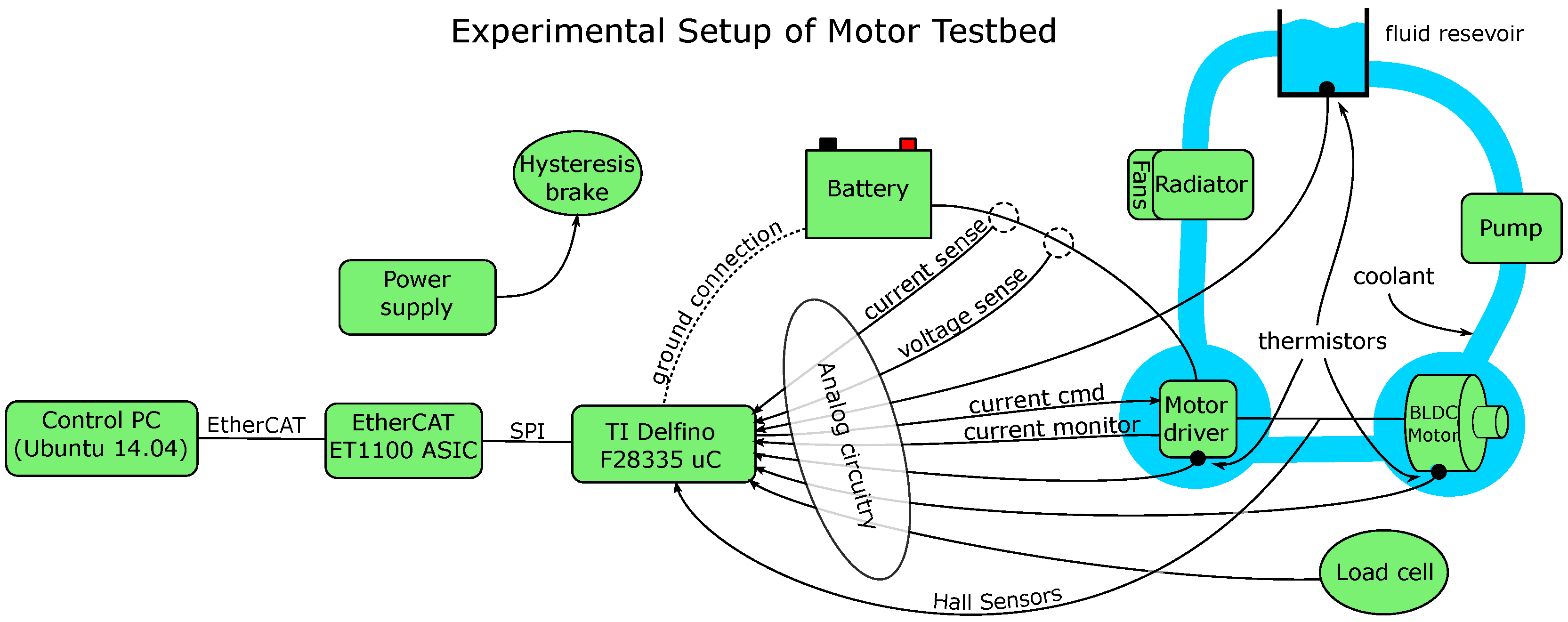
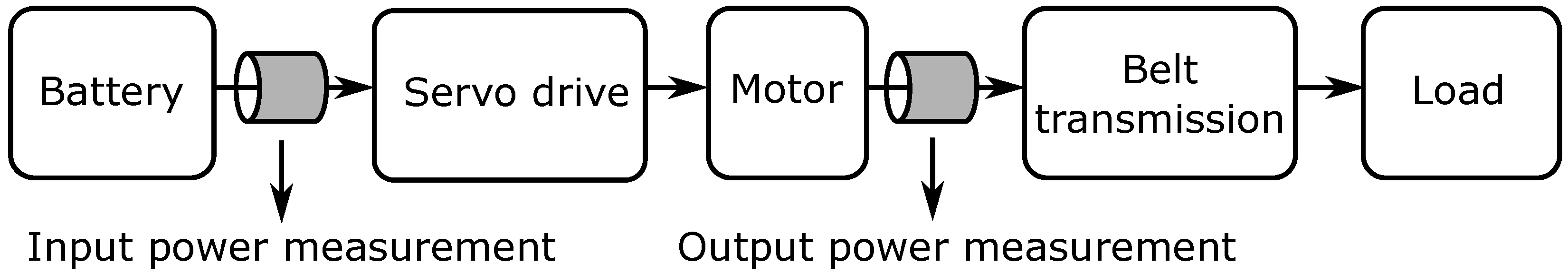
The work presented here aims to help solidify the understanding of liquid cooling as applied to COTS electric motors. Specifically, empirically-measured factors of improvement are provided not only for continuous current, but also for continuous power output. These results are gathered on a specially-designed and heavily-instrumented testbed that also measures actuation efficiency versus load. An abundance of temperature sensors enables direct measurement and comparison of the motor’s thermal resistance in air- and liquid-cooled scenarios. In addition to this performance study, an effective design for a retrofitted liquid-cooled motor housing is proposed. The design improves upon existing work in that it is non-permanent and removable. This feature facilitates periodic maintenance and component reuse, key features for a well-designed machine. Overall, the results obtained in this work benefit future designers, providing insight towards expected performance improvements based on simple motor datasheet parameters. The presented approach extends the reach of liquid-cooled motor applications beyond their current high-cost/custom-designed niche and thus brings their performance benefits to a wider community.
The remainder of this paper is structured as follows. Section 2 introduces simple models for the thermal behavior of electric motors. These models are then analyzed to establish the rules that govern maximum continuous motor torque as a function of a motor’s thermal properties. A motor core temperature estimation technique is also described, which offers protection from motor core burnout. 
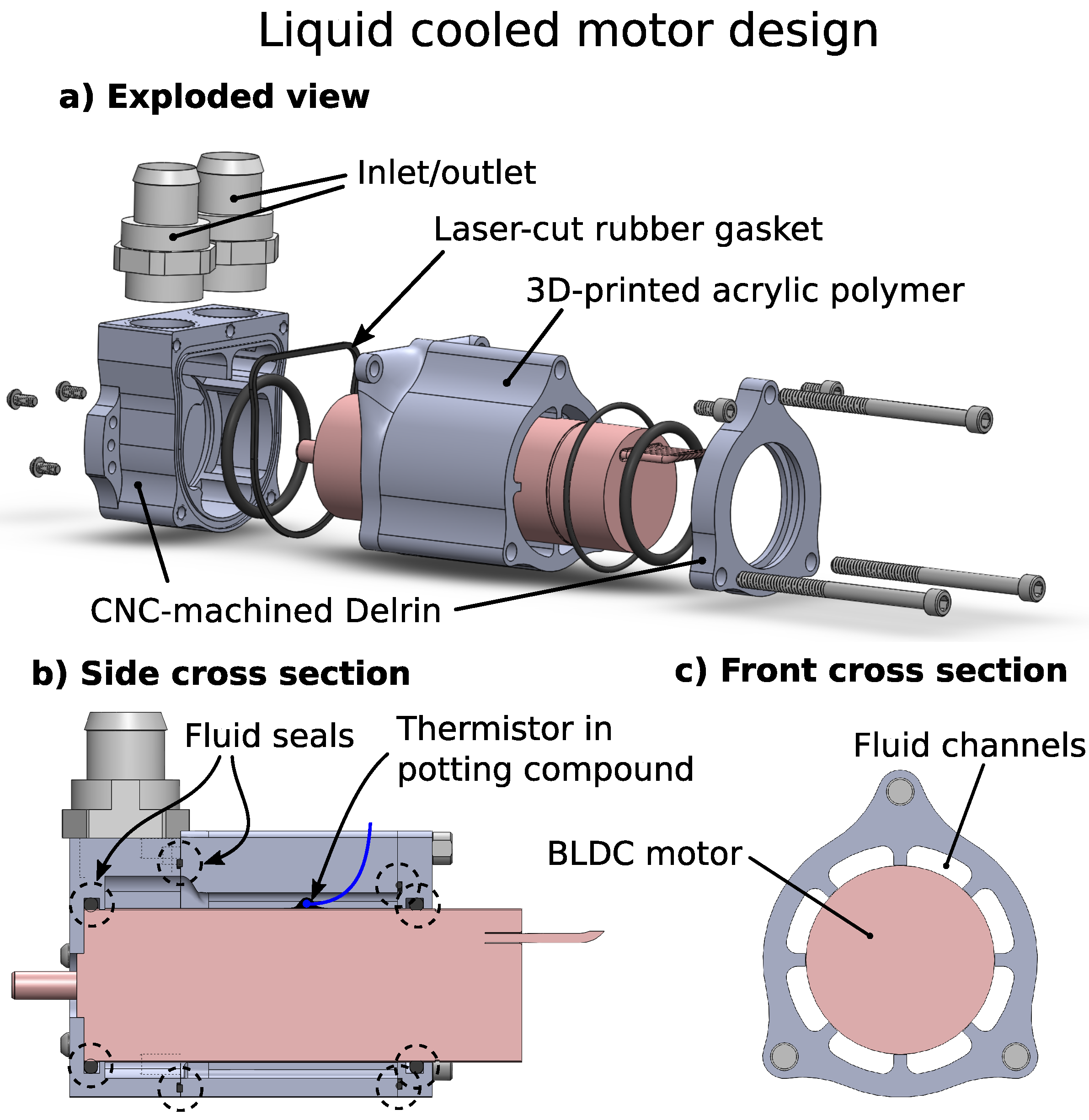
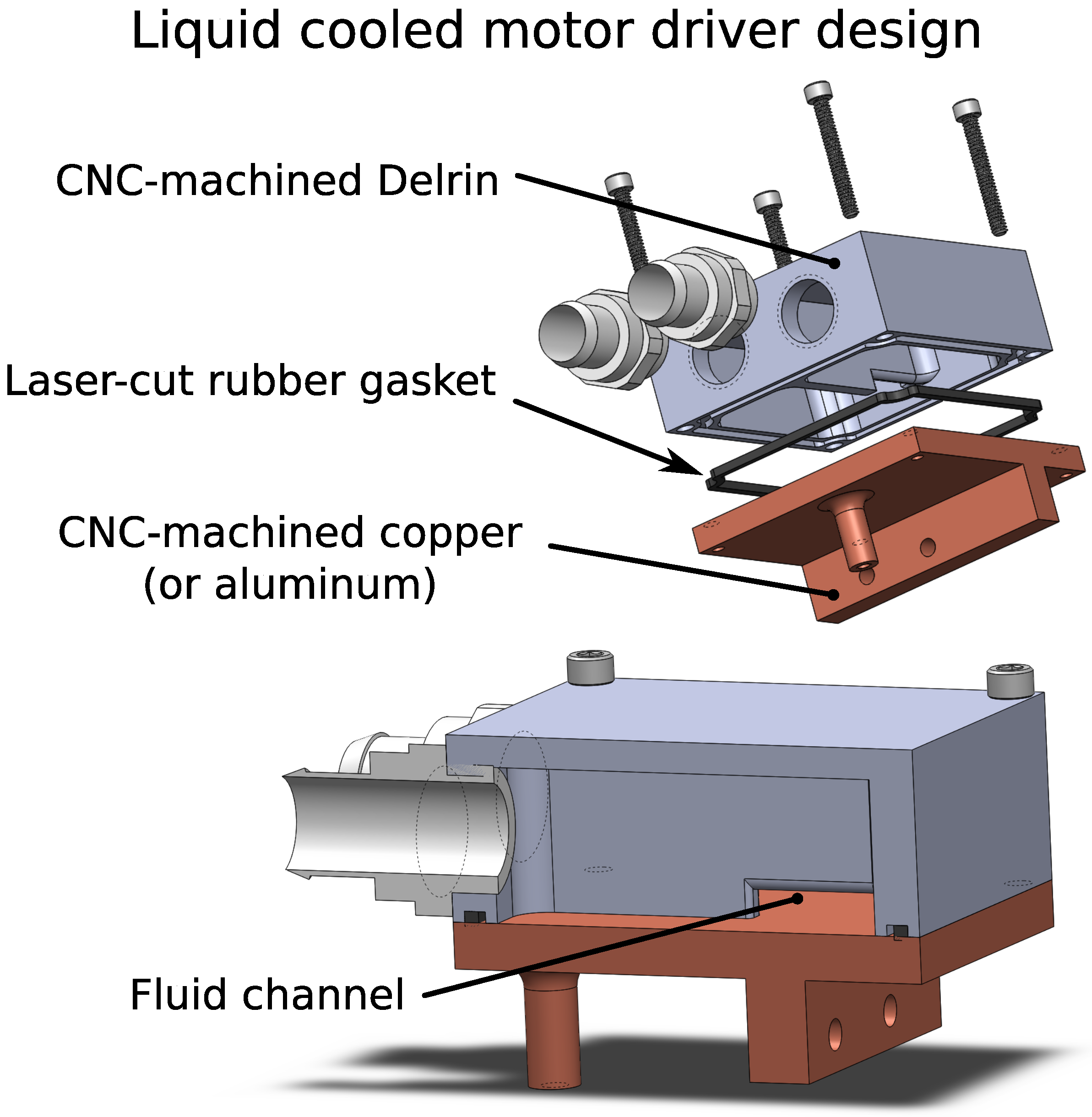
Section 3 presents a new design for retrofitted liquid-cooled motors and motor drivers. It also discusses issues pertinent to the selection of COTS motors for liquid cooling applications. Comparative experimental results between air-cooled and liquid-cooled motors are then shown and analyzed in Section 4. Section 5 then concludes the paper after a brief discussion.

2. Thermal Modeling of Electric Motors

This section gives a brief overview of the models and underlying concepts used in the experimental portion of the paper. It focuses on simple models for the thermal behavior of electric motors and establishes rules that govern maximum continuous torque and the effects of heat dissipation. For a supplemental discussion, refer to [4,20,24].
As energy transducers, electric motors convert electric energy into mechanical energy. However, loss is incurred in the process and manifests itself as heat generated by the motor. Two main sources of loss contribute to this heating: mechanical friction and Ohmic loss (also referred to as Joule heating or resistive loss). Ohmic loss ( P e ) depends on instantaneous motor current (I) and on the winding resistance ( R e ):
P e = I 2 R e .
At a small motor load, mechanical friction is the largest source of loss, while Ohmic loss dominates at larger loads [24]. For the remainder of this discussion, we focus on the second case and neglect the relatively small losses due to mechanical friction.
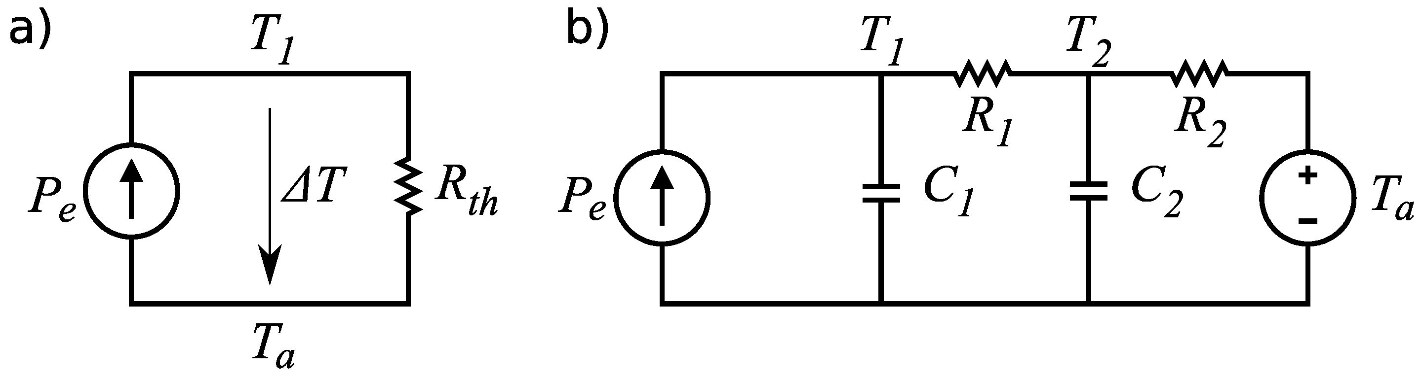
A simple circuit model, shown in Figure 1a, describes the steady-state thermal behavior of an electric motor subject to Ohmic losses. Heat current ( P e ) is injected into the system and is dissipated to the surrounding environment through a lumped thermal resistance ( R t h ) representing the combined effects of conduction, convection and radiation. A temperature difference ( Δ T ) is produced between the motor’s core temperature ( T 1 ) and the ambient air temperature ( T a ). At steady state, the motor core temperature can be calculated using Ohm’s law,
P e = Δ T R t h = T 1 - T a R t h .
Figure 1. Two models of motor thermal behavior. (a) A simple steady-state model. Given the thermal resistance R t h , Ohmic losses P e and ambient temperature T a , the motor core temperature T 1 can be calculated. (b) A more accurate thermal model. Given winding-to-housing thermal resistance R 1 and capacitance C 1 and housing-to-ambient thermal resistance R 2 and capacitance C 2 , the motor’s thermal transient response can also be modeled.
Actuators 04 00182 g001
Given the maximum permissible motor winding temperature ( T 1 m a x ), we can combine Equations (1) and (2) to calculate the maximum thermally-permissible continuous current,
I c = T 1 m a x - T a R t h R e
noting that R t h is a thermal resistance, while R e is an electrical resistance.
Equation (3) depends on R e , which is itself a function of temperature. This relationship is defined by the resistor temperature coefficient equation [25],
R e ( T ) = R o [ 1 + α ( T - T o ) ]
where R o is the nominal resistance at the nominal temperature ( T o ) and α is the winding material’s temperature coefficient (copper has an α of around 0.0039 Ω / K ).
From Equation (3), we can see how R t h plays a critical role in determining maximum continuous current. The other parameters, T 1 m a x , T a and R e , cannot be significantly altered from nominal values. Alternatively, R t h is very sensitive to design and environmental factors.
To further this analysis, consider the thermal model illustrated in Figure 1b. Here, additional elements are included: R 1 to represent the thermal resistance between the motor core and the motor housing, C 1 to represent the thermal capacitance of the motor’s core, R 2 to represent the thermal resistance between the motor housing and the environment, C 2 to represent the thermal capacitance of the motor’s housing and T a to represent ambient temperature. Several motor manufacturers provide these parameters in motor datasheets. This model improves over Figure 1a in that it more accurately captures the transient response of the motor to a thermal load and also breaks down the lumped thermal resistance into two distinct components.
From Equation (3), it is clear that R t h must be minimized to maximize a motor’s torque to mass ratio. This is a central consideration for any high-performance motor design and is often addressed either by using forced convective air cooling [1] or by adopting liquid cooling [10,12,18]. Table 1 demonstrates the benefits of liquid cooling with water, where water exhibits up to a 50× improvement in convective heat transfer compared to air. Table 1 gives a range for each situation due to a number of factors affecting convective heat transfer, such as the rate of fluid flow and surface shape.
Table 1. Typical values for mean convective heat transfer coefficient [26].
Flow Situation and FluidMean Heat Transfer Coefficient [W/(m 2 K)]
Free convection in air3 to 20
Forced convection in air10 to 200
Free convection in water20 to 200
Forced convection in water40 to 10,000

2.1. Thermal Ratio

In the case of liquid cooling, custom motor designs typically pass cooling fluid as close to the heat-generating windings as possible in order to reduce R t h . However, custom motor designs are not always possible, either for cost, time or complexity reasons. An alternative design is to apply liquid cooling to COTS motors to improve their performance [20,21,22]. In this case, the fundamental design of the motor cannot be altered. This consideration implies that R 1 must stay fixed while R 2 may be reduced using liquid cooling. Taking this constraint into consideration, we can define the thermal ratio (ρ) of a motor to be the maximum achievable improvement of continuous current (Equation (3)) assuming R 1 must remains fixed and R 2 can be made close to zero using liquid cooling. The thermal ratio is derived by taking the ratio of two continuous currents, one with with R t h = R 1 , ( I c l ) and the second with R t h = R 1 + R 2 , ( I c a ):
ρ = I c l I c a = R 1 + R 2 R 1 .
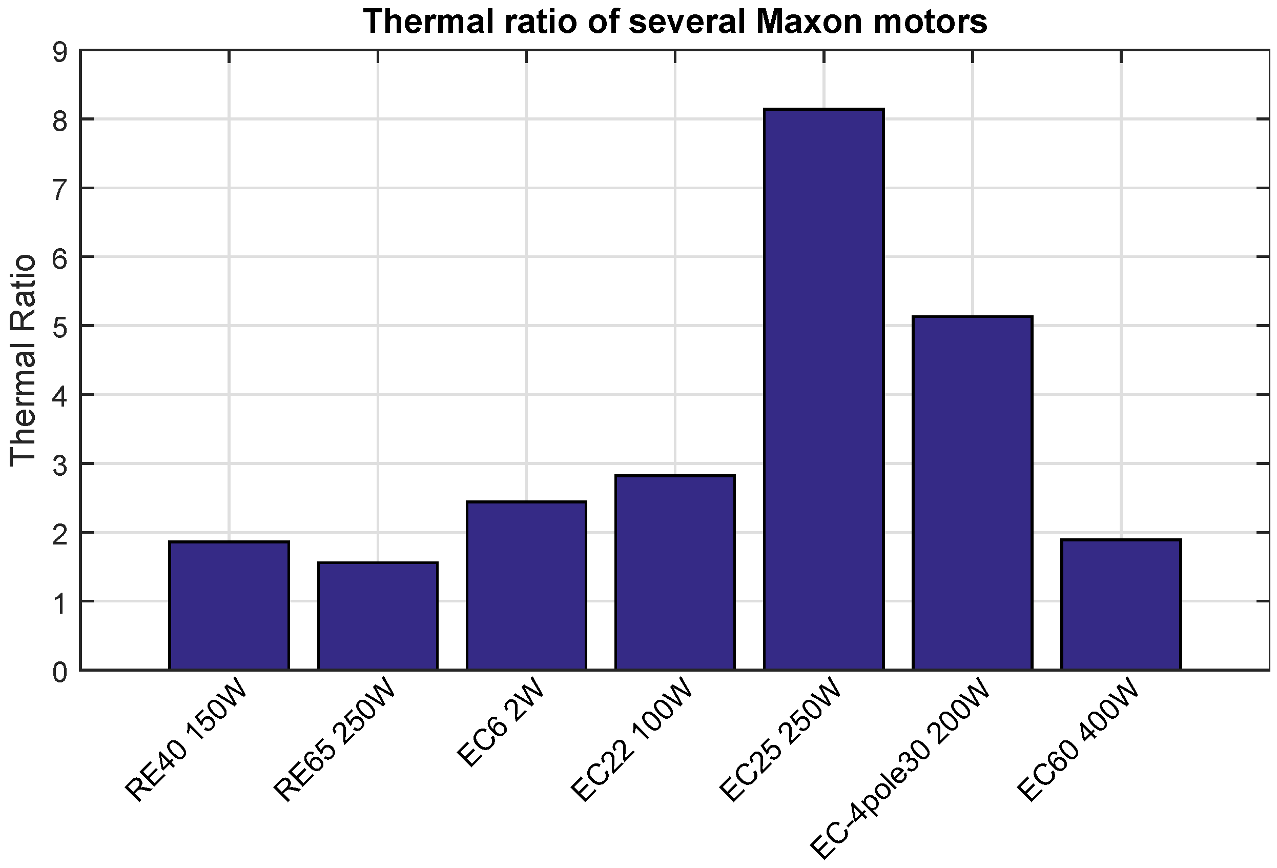
Figure 2 shows the thermal ratio for several Maxon motors. As the figure shows, the type of motor and its design significantly affect the potential benefit of adding liquid cooling. Assuming the added heat can be adequately dissipated, a central issue that will be discussed further in Section 5, the EC25 250 W Maxon motor should be able to tolerate over 8× the continuous current of air cooling when liquid cooling is applied, while the RE65 250 W motor’s continuous current is only increased by 1.56×.
Figure 2. Thermal ratios of several Maxon motors. The thermal ratio is the theoretical improvement factor in continuous current of liquid cooling versus air cooling. Part numbers beginning with `RE’ are brushed DC motors, while part numbers beginning with `EC’ are brushless DC motors.
Actuators 04 00182 g002

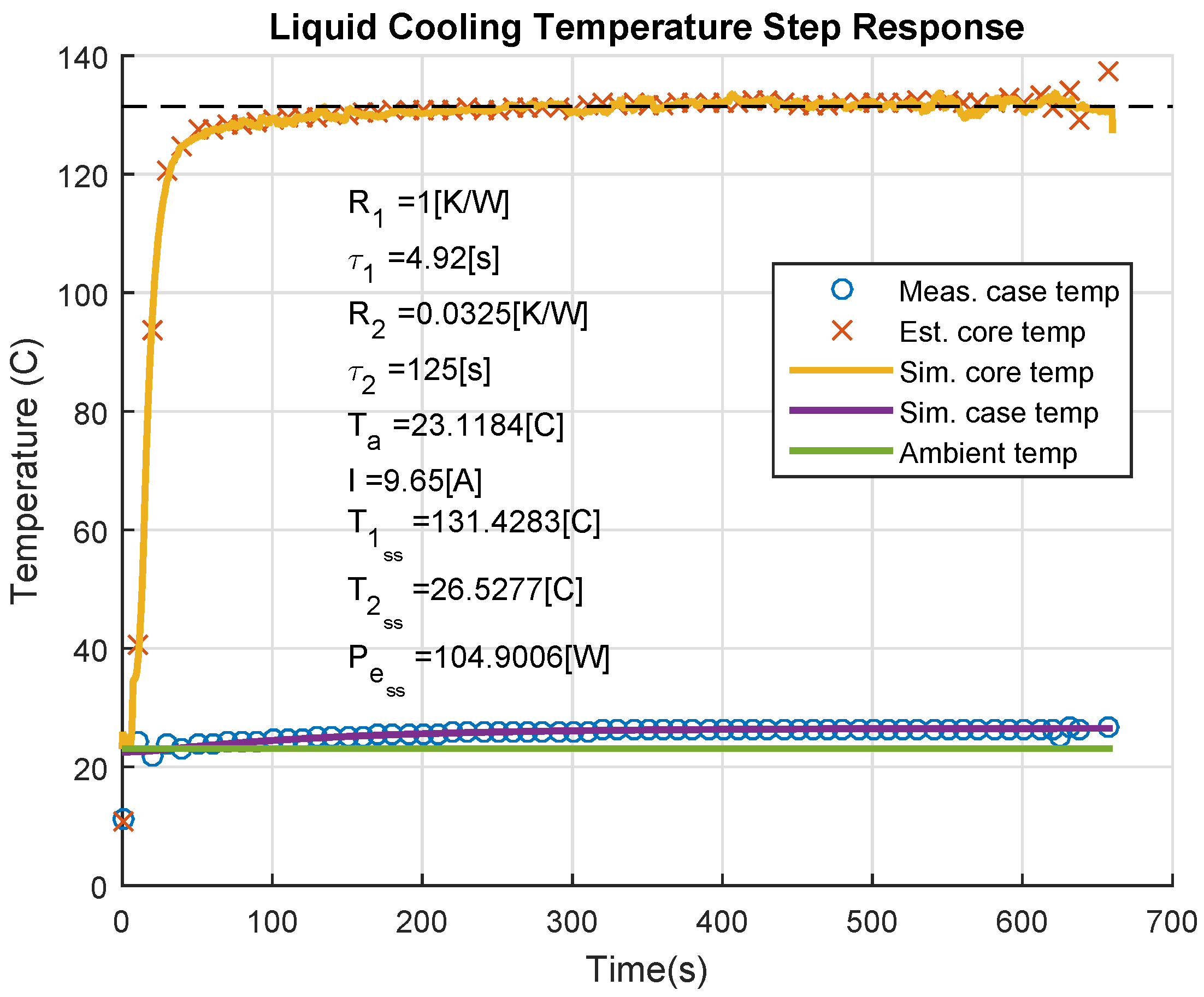
2.2. Core Temperature Estimation

While liquid cooling may significantly improve continuous current output of electric motors, it does not have the same effect on short-term current output. To gain insight into the maximum permissible short-term current output, [20] introduced the thermal control concept, which is a method to estimate the core motor temperature based on current and previous state measurements. This method is more effective than placing a temperature sensor directly on the motor’s windings due to the temperature difference between the winding core and its surface and the winding’s associated thermodynamics. Here, the thermal control approach is briefly described and is applied later in Section 4.
Two differential equations fully describe the thermal circuit model shown in Figure 1b:
d T 1 d t = 1 C 1 P e - T 1 - T 2 R 1
d T 2 d t = 1 C 2 T 1 - T 2 R 1 - T 2 - T a R 2
Given accurate initial conditions and measurements of P e (by measuring motor current) and T a , these equations can be integrated in real time using, for example, Euler integration, to estimate the values of T 1 and T 2 . If T 2 is directly measured, as it is in our experimental testbed, then T 1 can be calculated from Equation (6a) alone.

3. Design of the Liquid-Cooled Motor System

This section describes the design of a retrofitted liquid-cooled motor and the auxiliary systems required for accurately measuring and characterizing its performance.

3.1. Motor Selection

Motor selection was driven by a variety of factors. In addition to the typical motor performance requirements, such as large torque/mass and power/mass, a COTS motor used with liquid cooling should satisfy several additional requirements:
  • High magnetic saturation: Because of the large currents experienced with liquid cooling, these large currents must not saturate any flux-producing elements of the motor. Motors with iron cores are more susceptible to this effect than are coreless motor designs [27].
  • Low thermal resistance: The proximity of the heat-generating winding to the outside surface of a motor varies greatly by motor type and motor design (refer back to Figure 2). In the case that R 1 and R 2 are not provided by the motor manufacturer, motor designs featuring stationary windings with a short thermal path to the liquid-cooled surface are desirable. Motor types matching these characteristics are internal rotor brushless DC/AC motors and stepper motors. Poor candidates are external rotor brushless DC/AC, brushed DC, universal and induction motors.
In the present case, along with a desired power range of 100 W to 200 W, the following two metrics were used to choose the EC22 100-W motor from the Maxon catalog:
Continuous Power · Thermal Ratio Mass · Cost
Continuous Torque · Thermal Ratio Mass · Cost
Table Table 2 shows the datasheet thermal parameters for the EC22 100-W motor.
Table 2. Maxon EC22 100-W datasheet thermal parameters.
ParameterValueUnits
R 1 1K/W
R 2 7K/W
R e 0.797Ω
T 1 m a x 155C
From Equation (5), the thermal ratio for this motor is calculated to be 2.83, yielding a theoretical air-cooled continuous current of 3.71 A (Equation (3)) assuming an ambient temperature of 25 C. For this case, Ohmic losses would be 16.2 W. Using liquid cooling, continuous current is increased to 10.5 A, generating Ohmic losses of 130 W. The next section describes how this large amount of heat is efficiently carried away from the motor case.

3.2. Retrofitted Liquid-Cooled Motor Housing Design

A fluid conducting housing was designed to fit a Maxon EC22 100-W motor with three main goals: (1) provide a water-tight seal around the motor for the 1.5-bar fluid pressure generated by the liquid cooling pump; (2) ensure the fluid is circulated over the entire surface of the motor, limiting eddy currents where possible; and (3) produce a design that may be disassembled for cleaning and maintenance if needed.
To satisfy these requirements, a unique design was developed that is composed of three sections (see Figure 3). The front-most sections, where the motor’s output shaft is located, serve as both the mechanical and fluid interface for the motor. Requiring mechanical strength, corrosion resistance, chemical inertness and high machining tolerances, this section is CNC-machined from Delrin plastic (also known as polyoxymethylene). Two fluid seals, one a COTS silicone O-ring with a 70-A durometer hardness and one custom-designed laser-cut from EPDM (ethylene-propylene-diene monomer) rubber with a 60-A durometer hardness are designed for a 30% squeeze (O-ring compression) to provide a watertight barrier.
The middle section of the liquid-cooled motor housing circulates the fluid around the full surface of the motor, following a ribbed design similar to that of [22]. Requiring lower tolerances (±0.127 mm), cost is saved by 3D printing this part from watertight acrylic polymer using a UV curing process. An additional set of O-rings provides a seal to the third, rear-most part of the housing, which is retained to the rest of the assembly with screws. Unlike [22], which uses sealing adhesive to join housing components together, this O-ring-based design better facilitates disassembly, allowing for component reuse and periodic maintenance, if required.
Figure 3. Design of a casing to house and circulate cooling fluid around the Maxon EC22 100-W motor.
Actuators 04 00182 g003
Motor case temperature is measured using a pre-calibrated thermistor. The thermistor is secured to the motor case with thermally-conductive epoxy (also known as potting compound) with a thermal conductivity of 0.682 W/mK, similar to that of water. One hole must be drilled into the middle part of the liquid cooling housing assembly through which the thermistor’s leads are routed. A non-permanent room-temperature vulcanized silicone rubber seal is used at this interface.

3.3. Retrofitted Liquid-Cooled Servo Drive Water Block Design

Because motor current also must pass through the motor servo drive, a water block was designed to cool this component, as well. Its design requirements are similar to that of the motor’s liquid cooling housing. Figure 4 illustrates this design. CNC-machined Delrin is again used for the body of the assembly, while a custom-designed gasket provides the watertight seal. Copper was chosen to carry heat away from the servo drive (Advanced Motion Controls AZB60A8), but aluminum will likely be used in the next iteration for its lower density. A single channel is machined into the housing of the water block to force liquid to pass over the portion of the heat sink where heat is most concentrated.
The remaining liquid cooling components such as the radiator, reservoir, pump and fittings, were obtained from Swiftech, a personal computer (PC) liquid cooling company. High-flex PVC (polyvinyl chloride) tubing was used to connect these components together. Optimal sizing of the liquid cooling components remains an important question to be addressed in future work. In the present testbed, the flow rate of the coolant through the combined fluid resistances of the motor housing, servo drive water block and radiator was measured to be 0.036 L/s.
Figure 4. Design of a casing to house and circulate cooling fluid around the Advanced Motion Controls AZB60A8 motor driver.
Actuators 04 00182 g004

3.4. Instrumentation and Dynamometry Design

A controllable motor load and a large suite of sensors is necessary to enable thermal control and to fully characterize motor performance (see Figure 5 and Figure 6). A hysteresis brake (Magtrol HB-840) capable of dissipating 300-W continuous and 1340-W peak power is used as a variable motor load. With a thermal ratio of 2.83, the liquid-cooled EC22 100-W motor is expected to produce 283 W of power continuously. The brake’s maximum speed is 6000 rpm, while the motor’s maximum speed, driven by a 64-V battery supply, is 43,000 rpm. Therefore, a 7.68:1 two-stage pulley speed reduction is used between the motor and the hysteresis brake to match their respective maximum speeds.
The following measurements are taken on the motor testbed:
  • Motor torque is measured using a reaction torque sensor (Futek TFF325).
  • Motor speed is measured based on the time between hall sensor signal pulses.
  • Motor current is monitored using feedback from the motor servo drive (Advanced Motion Controls AZB60A8).
  • Bus voltage is measured directly across the battery output terminals.
  • Bus current is measured from the negative battery terminal lead using a Hall effect sensor.
  • Motor case temperature is measured using a potted negative temperature coefficient (NTC) thermistor.
  • Servo drive temperature is measured using a potted NTC thermistor.
  • Fluid reservoir temperature is measured using an NTC thermistor.
Figure 5. The motor testbed used in Section 4. This picture shows the testbed as configured for liquid cooling. For air cooling tests, a bare motor was used. This system is interfaced to a Texas Instruments TMS320F28335 microcontroller (refer to Figure 6 below).
Actuators 04 00182 g005
Figure 6. A block diagram showing the hardware interface used for experimental testing. Data are gathered on a Texas Instruments TMS320F28335 microcontroller and then passed to a control PC via EtherCAT.
Actuators 04 00182 g006
Coupled with the programmable hysteresis brake, this set of sensors enables thermal control and also direct measurement of input power, output power and, therefore, overall actuation system efficiency. Efficiency is measured as the ratio of mechanical output power to electrical input power as illustrated in Figure 7. For efficiency measurement in this paper the additional power consumption of the liquid cooling pump is not considered. In the present testbed, the power consumed by the pump is relatively small compared to the maximum continuous power consumed by the motor (2.2%, 12 W versus 533 W). In a real robotic system, this discrepancy would likely be larger, since a single pump can provide fluid flow to multiple motors. The efficiency measured by the testbed does include hysteresis, eddy current and Ohmic losses in the motor, as well as switching and Ohmic losses in the motor driver.
Figure 7. Location of power measurements in the motor testbed. Electrical power is measured from the power source (batteries) as voltage times current. Mechanical power is measured at the motor’s output as angular velocity times torque. Measured efficiency therefore includes the motor and servo drive losses.
Actuators 04 00182 g007

4. Experimental Comparison between Air- and Liquid-Cooled Motors

The central goal of this work was to empirically determine and compare the maximum continuous power and torque production of air- and liquid-cooled motors. To achieve this objective, the problem was subdivided into four stages or experiments:
  • Experiment 1: establish the maximum continuous motor current using air cooling and a fixed load.
  • Experiment 2: measure the maximum output power and torque using continuous current, air cooling and a variable load.
  • Experiment 3: establish the maximum continuous motor current using liquid cooling and a fixed load.
  • Experiment 4: measure the maximum output power and torque using continuous current, liquid cooling and a variable load.

4.1. Experimental Setup

Motor commands and all sensor data were interfaced through a Texas Instruments TMS320F28335 microcontroller as depicted in Figure 6. Data were transmitted to a control PC running Ubuntu 14.04 via EtherCAT fieldbus. Due to the long duration of each test, sample rates between 100 Hz and 20 Hz were used. The hysteresis brake was interfaced to a separate power supply, and its torque, which is measured with the testbed torque sensor, was set manually. Five 12-V lead acid batteries were used to supply between 60 V and 70 V to the motor driver.
In the process of performing tests that reach the maximum safe motor core temperatures, it is important to be able to discern if and when damage to the motor occurs. System operating efficiency is used for this purpose, and it is assumed that it corresponds to the health of the motor. Between each high current experiment, a test is run to measure system operating efficiency. In this way, we are able to detect if and when motor damage occurs.

4.2. Experiment 1: System Identification of Air-Cooled Motor

In this experiment, a stock motor without liquid cooling was used. The commanded motor current was first calibrated against an oscilloscope current probe attached to the motor phase wires. After calibration, a constant current was applied to the motor, and the hysteresis brake torque was set such that a low motor speed was achieved (between 2000 rpm and 3000 rpm). Through trial and error, the magnitude of the current was set such that the estimated core motor temperature would reach close to a steady-state value of 155 C, the maximum rated winding temperature. Figure 8 shows the final result.
Figure 8. Thermal step response of the Maxon EC22 100-W motor with air cooling. A current amplitude of 4.07 A was used. This amplitude was empirically determined and causes the core motor temperature to reach an estimated steady-state value of 141.9 C (a safety margin of 13.1 C compared to the maximum rated value of 155 C). The core temperature was estimated using the thermal control technique described in Section 2.2. Actual data are plotted as points, while the lines are simulated responses and were used to fit the thermal model (from Figure 1b) to the data.
Actuators 04 00182 g008
Figure 8 also shows the empirically-identified thermal model parameters R 1 , τ 1 = R 1 C 1 , R 2 , τ 2 = R 2 C 2 , along with the experimental parameters. Our identified thermal parameters match the datasheet values except for R 2 , which is 74% of the datasheet value (5.2 K/W vs. 7 K/W). This is an acceptable difference given the sensitivity of thermal resistance to environmental conditions, such as mounting conditions, air currents, etc. The simulated core temperature (Sim. core temp) and case temperature (Sim. case temp) lines are extrapolations of the experimental data and are used to determine the steady-state value of the core temperature. These simulated values are generated using a Simulink model of the thermal circuit (Figure 1b).
The end result of this experiment is a continuous current value of 4.07 A (corresponding to 0.06 Nm of torque), which is 14% greater than the datasheet value of 3.57 A. This difference is due to the discrepancy between the datasheet and measured R 2 value. This continuous current and torque will serve as our baseline for comparison with the liquid cooling experiments.

4.3. Experiment 2: Maximum Power and Torque Output with Air Cooling

With the maximum continuous air-cooled current empirically determined, this current was then applied across the full operating range of the motor, from no load to a fixed load. This was achieved by first applying zero load torque with the hysteresis brake, causing the motor to spin up to no-load speed and then gradually increasing load torque to the point where the motor stopped rotating.
Figure 9. This figure shows the maximum mechanical output power (213 W at 85.6% efficiency) achievable using the maximum air-cooled steady-state current of 4.07 A. These data were obtained by setting a constant motor current and then varying the motor’s load from zero load to a fixed load. The subfigures show: (a) motor velocity response, (b) motor input and output power, and (c) instantaneous motor operating efficiency.
Actuators 04 00182 g009
The results of this experiment are shown in Figure 9. Figure 9a shows motor velocity, which first rises rapidly to the no-load speed, decreases with increasing load until it reaches the constant torque region and then decreases linearly to zero. Figure 9b shows both electrical input power and mechanical output power. Power data were filtered with a zero-phase moving average filter with a window size of 1.5 s. From this plot, the maximum continuous power point can be identified (213 W at 25.4 s). Figure 9c shows the overall system efficiency. The efficiency during peak power output is 85.6%. Efficiency peaks at around 92.5%, which is close to the datasheet value of 90%.

4.4. Experiment 3: System Identification of the Liquid-Cooled Motor

For the third experiment, liquid cooling was installed onto the motor and the servo drive. As an initial test, the motor current was set to follow a 7-A sine wave with no fluid circulation (see Figure 10). Then, after the motor case temperature had risen to 50 C, the pump for the liquid cooling system was turned on. In one second, the case temperature dropped by 24 C back to ambient temperature (23.2 C), demonstrating the importance of fluid flow in the convective heat transfer of liquid cooling.
Figure 10. This figure demonstrates the effect of fluid flow on cooling performance. From t = 0→180 s, a sinusoidal current with an amplitude of 7 A, generating peak Ohmic losses of around 40 W, is applied to the motor. During this time, fluid around the motor is slowly heated. At t = 180 s, the liquid cooling pump is turned on, causing the fluid to begin flowing past the radiator. A rapid decrease in motor case temperature follows, dropping 24 C back down to ambient temperature in 1 s.
Actuators 04 00182 g010
To identify the maximum steady-state current, the commanded currents were increased until the maximum core temperature was reached with a safety margin of 24 C. Figure 11 demonstrates the identified maximum continuous current of 9.65 A (0.15 Nm of torque), reaching a core temperature of 131 C. Note that the identified model for this case uses an R 2 value of 0.0325 K/W, meaning that the thermal resistance is smaller than that of ambient air cooling by a factor of 160 (5.2/0.0325). This is a significant improvement and is also sufficiently close to zero to verify the assumption of setting R 2 to zero to calculate the thermal ratio, as described in Section 2.1.
Figure 11. Thermal step response of the Maxon EC22 100-W motor with liquid cooling. A current amplitude of 9.65 A was used. This amplitude was empirically determined and causes the core motor temperature to reach an estimated steady-state value of 131.42 C. The core temperature was estimated using the thermal control technique described in Section 2.2. Experimental data are plotted as points, while the lines are simulated responses and were used to fit the thermal model (from Figure 1b) to the data.
Actuators 04 00182 g011

4.5. Experiment 4: Maximum Power and Torque Output with Liquid Cooling

The experimental procedure for the fourth experiment mirrored that of Experiment 2. The maximum liquid-cooled continuous current was set, and the load was then decreased from no load to a fixed load. Velocity, power and efficiency were measured as shown in Figure 12. Figure 12b shows that the maximum continuous power was produced at t = 20.4 s, reaching a value of 430 W at 83.4% overall efficiency. Surprisingly, despite the dramatic increase in power by a factor of two, the overall decrease in efficiency between these two operating points is only 2.2% (85.6% versus 83.4%).

4.6. Empirical Comparison of the Cooling Methods

By compiling the various trials of Experiments 1 and 3, the performance of air cooling can be directly compared against that of liquid cooling. Figure 13 shows these results. The data points on the plot are the steady-state temperatures gathered during the separate trials of Experiments 1 and 3. A best fit curve was applied to both sets of data to allow direct comparison of the two cooling methods at the same steady-state core temperature. Based on this approach, liquid cooling the Maxon EC22 100-W motor results in an improvement in steady-state current by a factor of 2.58. This empirical value matches to within 9% of the motor’s datasheet thermal ratio value of 2.83 and is lower due to the experimental discrepancy of the R 2 parameter.
Figure 12. This figure shows the maximum mechanical output power (430 W at 83.4% efficiency) achievable using the maximum liquid-cooled steady-state current of 9.65 A. These data were obtained by setting a constant motor current and then varying the motor’s load from zero load to a fixed load.
Actuators 04 00182 g012
Figure 13. This figure compares the performance of air versus liquid cooling as applied to the COTS Maxon EC22 100-W motor. Here, the performance metric is steady-state continuous current. Maximum current is defined to be the current that produces a steady-state core temperature of 155 C. By this metric, liquid cooling outperforms air cooling by a factor of 2.58 (4.07 A versus 10.5 A) for the Maxon EC22 100-W motor. This factor is motor dependent, but is accurately approximated (in this case to within 9%) by the motor’s thermal ratio (2.83 for the Maxon EC22 100 W; refer back to Section 2.1).
Actuators 04 00182 g013

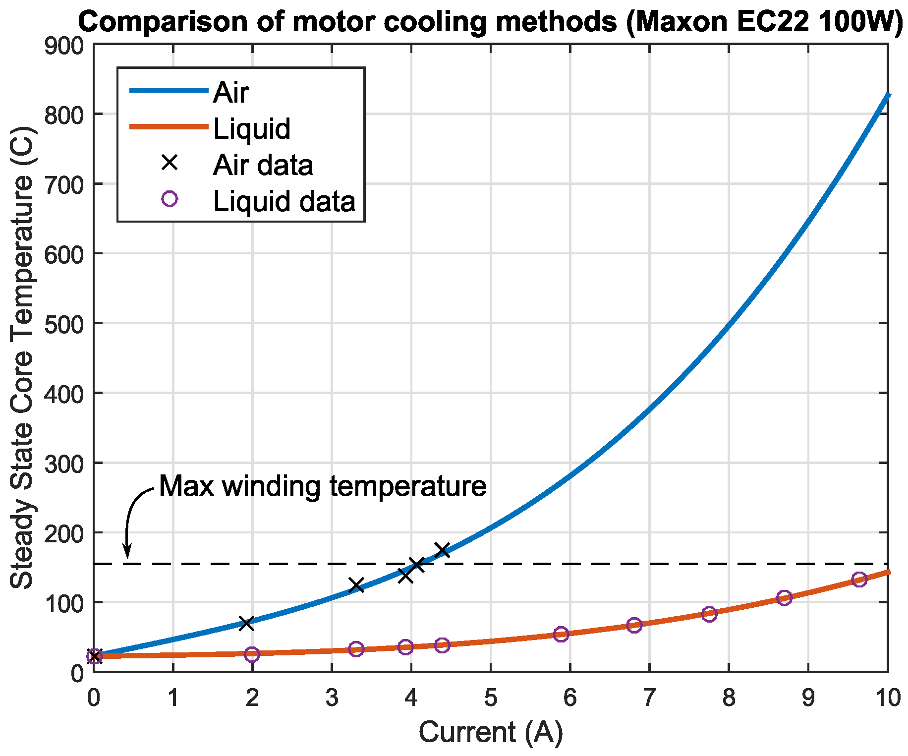
5. Conclusion and Discussion

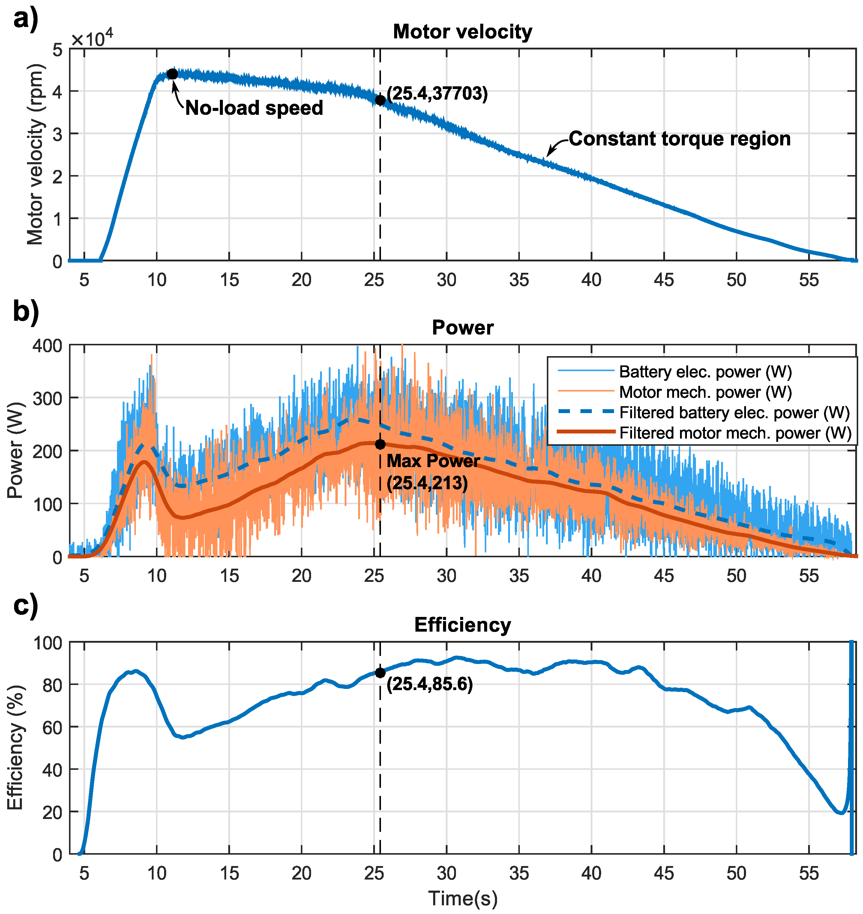
This paper directly compared the achievable torque and power improvements yielded by constructing a retrofitted liquid cooling system for a COTS electric motor. It was found that, for the Maxon EC22 100 W motor, 2.58-times higher current and torque output could be safely obtained with the liquid-cooled motor compared to the same motor with air cooling. This improvement factor closely matched the motor’s thermal ratio, a theoretical value that can be directly calculated from datasheet motor parameters. This empirical validation is the main contribution of the paper and enables future designers to place confidence in and have intuition towards active cooling performance for COTS motors. An increase in continuous power output by a factor of two between the two cooling methods was also measured, and importantly, this increase fostered a mere 2.2% decrease in operating efficiency. This observation suggests that liquid cooling may also serve roles in actuators with strict energy consumption requirements, yet that are required to produce high energy output periodically.
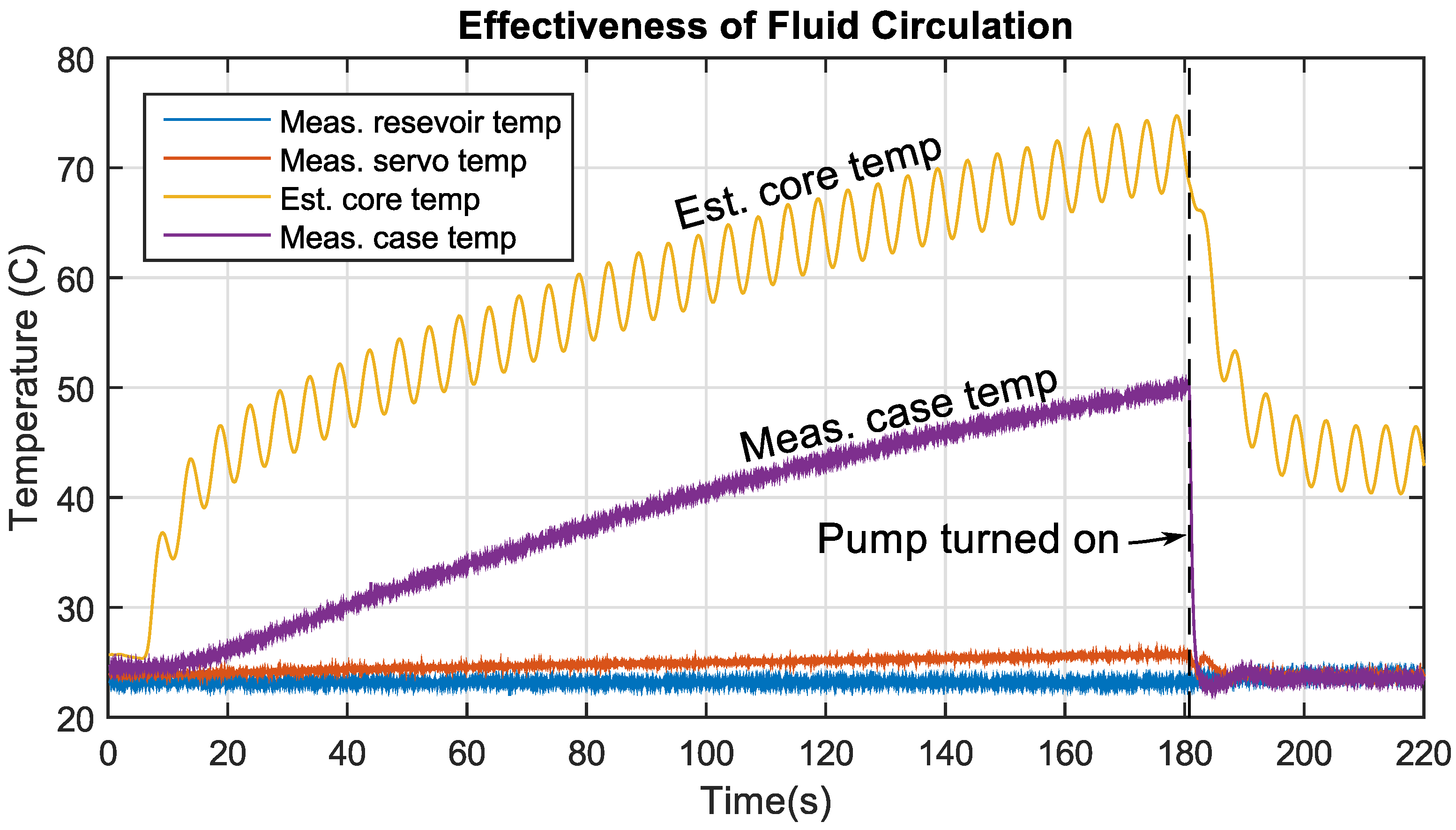
We presented a new design for a retrofitted liquid cooling housing, which features high cooling performance (reaching a thermal resistance of R 2 = 0.035 K/W), but that is based on a non-permanent O-ring-sealed structure. This improves over existing designs in that the cooling structure can be disassembled and cleaned periodically. The empirical measurement of the parameter R 2 is also useful in that it provides a data point for the performance of the heat convection in liquid-cooled COTS motors. Comparing the value of R 2 with liquid cooling (0.035 K/W) against its air-cooled counterpart (5.2 K/W) resulted in a reduction of thermal resistance by a factor of 160. This yields a data point of 160 = 12 . 6 for the thermal ratio of a “thermally-optimized” motor, where R 1 0 , meaning cooling fluid is passed directly over the windings. This value is, of course, related to the many factors associated with our particular liquid-cooled system, such as the outside surface area of the Maxon EC22 100-W motor, the size of the radiator, the number of cooling fans used, etc., and therefore is not a hard theoretical limit, only a single, empirically-derived data point.
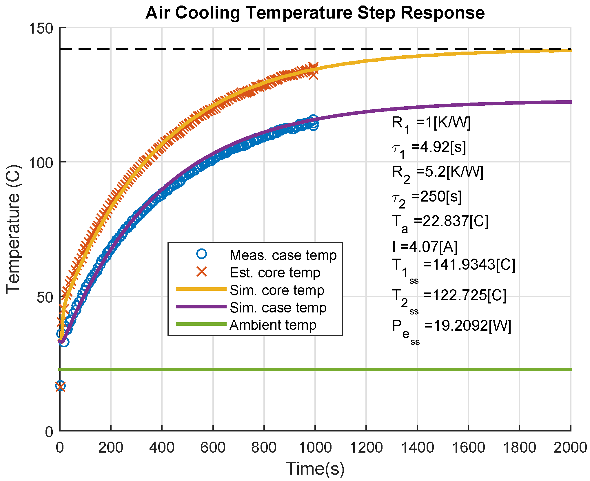
An additional question to ask is “how may these methods be applied to motors without pre-specified thermal properties?” In this case, a more thorough system identification process must be used where all four parameters, R 1 , C 1 , R 2 , C 2 are empirically identified. In this paper, R 2 was identified by commanding a constant current, letting the system reach a steady-state temperature and then measuring the difference between T 2 and T a . With R 2 identified, C 2 was found based on the system’s transient response. Accurately identifying R 1 and C 1 is more difficult. Approaches for measuring these values could leverage the fact that winding resistance is a function of temperature thus enabling its use as a temperature sensor.
Future work remains in the best sizing of liquid cooling components, such as the radiator, pump and tubing diameter for optimal system-wide power/torque per unit mass. Additionally, limited attempts were made in this work to optimize pressure versus flow characteristics of the motor and driver water blocks. Improvements here may improve cooling performance further, leading to improved empirically-measured thermal ratios.

Acknowledgments

The authors would like to thank Joseph Ho and Aloysius Mok for their contributions to this work.

Author Contributions

Nicholas Paine built the experimental testbed and wrote the majority of the manuscript text. Luis Sentis oversaw and directed the project and provided valuable input for the manuscript.

Conflicts of Interest

The authors declare no conflict of interest.

Abbreviations/Nomenclature

COTS
commercial off-the-shelf
CNC
computer numerical control

References

  1. Radford, N.A.; Strawser, P.; Hambuchen, K.; Mehling, J.S.; Verdeyen, W.K.; Donnan, A.S.; Holley, J.; Sanchez, J.; Nguyen, V.; Bridgwater, L.; et al. Valkyrie: NASA’s First Bipedal Humanoid Robot. J. Field Robot. 2015, 32, 397–419. [Google Scholar] [CrossRef]
  2. Veneman, J.F.; Kruidhof, R.; Hekman, E.E.; Ekkelenkamp, R.; Van Asseldonk, E.H.; Van Der Kooij, H. Design and evaluation of the LOPES exoskeleton robot for interactive gait rehabilitation. IEEE Trans. Neural Syst. Rehabil. Eng. 2007, 15, 379–386. [Google Scholar] [CrossRef] [PubMed]
  3. Ridley, J. The MRV: Next-Gen Automobile? Available online: http://www.electricvehiclesresearch.com/articles/7731/the-mrv-next-gen-automobile (accessed on 13 August 2015).
  4. Hunter, I.W.; Hollerbach, J.M.; Ballantyne, J. A comparative analysis of actuator technologies for robotics. In Robotics Review 2; MIT Press: Cambridge, MA, USA, 1991; pp. 299–342. [Google Scholar]
  5. Zoss, A.B.; Kazerooni, H.; Chu, A. Biomechanical design of the Berkeley lower extremity exoskeleton (BLEEX). IEEE/ASME Trans. Mechatron. 2006, 11, 128–138. [Google Scholar] [CrossRef]
  6. Pratt, G.A. DARPA-BAA-12-52: Broad Agency Announcement, Maximum Mobility and Manipulation, Actuation; Technical report; DARPA: Arlington, MA, USA, 2012. [Google Scholar]
  7. Caricchi, F.; Crescimbini, F.; Napoli, A.; Marcheggiani, M. Prototype of electric vehicle drive with twin water-cooled wheel direct drive motors. In Proceedings of the 27th Annual IEEE Power Electronics Specialists Conference, Baveno, Italy, 23–27 June 1996; Volume 2, pp. 1926–1932.
  8. Rahman, K.M.; Patel, N.R.; Ward, T.G.; Nagashima, J.M.; Caricchi, F.; Crescimbini, F. Application of direct-drive wheel motor for fuel cell electric and hybrid electric vehicle propulsion system. IEEE Trans. Ind. Appl. 2006, 42, 1185–1192. [Google Scholar] [CrossRef]
  9. Snitchler, G.; Gamble, B.; Kalsi, S.S. The performance of a 5 MW high temperature superconductor ship propulsion motor. IEEE Trans. Appl. Superconduct. 2005, 15, 2206–2209. [Google Scholar] [CrossRef]
  10. Everton, J.; Schofield, N. Design and testing of a liquid cooled brushless DC traction motor. In Proceedings of the IEE Colloquium on Motors and Drives for Battery Powered Propulsion, London, UK, 15 April 1993.
  11. Bianchi, N.; Gieras, J. Electric motors for light traction. EPE J. 2004, 14, 12–23. [Google Scholar]
  12. Laskaris, K.; Kladas, A.G. Liquid cooled permanent-magnet traction motor design considering temporary overloading. In Proceedings of the 2012 XXth International Conference on Electrical Machines (ICEM), Marseille, France, 2–5 September 2012; pp. 2677–2682.
  13. Van Es, J.; van Gerner, H.J. Benefits and Drawbacks of Using Two-Phase Cooling Technologies in Military Platforms; Technical report; National Aerospace Laboratory: Amsterdam, Netherlands, 2011. [Google Scholar]
  14. Rogers, S.; Boyd, S. Overview of the DOE Advanced Power Electronics and Electric Motor R&D Program; Technical report; U.S. Department of Energy: Washington, DC, USA, 2014.
  15. Asada, H.; Youcef-Toumi, K. Direct-Drive Robots: Theory and Practice; MIT Press: Cambridge, MA, USA, 1987. [Google Scholar]
  16. Hollerbach, J.; Hunter, I.; Lang, J.; Umans, S.; Sepe, R.; Vaaler, E.; Garabieta, I. The McGill/MIT direct drive motor project. In Proceedings of the 1993 IEEE International Conference on Robotics and Automation, Atlanta, GA, USA, 2–6 May 1993; pp. 611–617.
  17. Aghili, F.; Buehler, M.; Hollerbach, J.M. Development of a high-performance direct-drive joint. Adv. Robot. 2002, 16, 233–250. [Google Scholar] [CrossRef]
  18. Aghili, F.; Hollerbach, J.M.; Buehler, M. A modular and high-precision motion control system with an integrated motor. IEEE/ASME Trans. Mechatron. 2007, 12, 317–329. [Google Scholar] [CrossRef]
  19. Harmonic Drive LLC. Cup Type Component Sets & Housed Units. Available online: http://harmonicdrive.net/media/support/catalogs/pdf/csf-csg.pdf (accessed on 28 July 2015).
  20. Urata, J.; Hirose, T.; Namiki, Y.; Nakanishi, Y.; Mizuuchi, I.; Inaba, M. Thermal control of electrical motors for high-power humanoid robots. In Proceedings of the IEEE/RSJ International Conference on Intelligent Robots and Systems (IROS 2008), Nice, Italy, 22–26 September 2008; pp. 2047–2052.
  21. Urata, J.; Nakanishi, Y.; Okada, K.; Inaba, M. Design of high torque and high speed leg module for high power humanoid. In Proceedings of the 2010 IEEE/RSJ International Conference on Intelligent Robots and Systems (IROS), Taipei, Taiwan, 18–22 October 2010; pp. 4497–4502.
  22. Ito, Y.; Nozawa, S.; Urata, J.; Nakaoka, T.; Kobayashi, K.; Nakanishi, Y.; Okada, K.; Inaba, M. Development and verification of life-size humanoid with high-output actuation system. In Proceedings of the 2014 IEEE International Conference on Robotics and Automation (ICRA), Hong Kong, China, 31 May–7 June 2014; pp. 3433–3438.
  23. DARPA. The DARPA Robotics Challenge Trials. 2013. Avaiable online: http://archive.darpa.mil/roboticschallengetrialsarchive/ (accessed on 30 June 2015).
  24. Stemme, D.O.; Wolf, P. Principles and Properties of Highly Dynamic DC Miniature Motors; Maxon Motor: Sachseln, Switzerland, 1994. [Google Scholar]
  25. Kasap, S.O. Principles of Electronic Materials and Devices; McGraw-Hill: New York, NY, USA, 2006. [Google Scholar]
  26. Oosthuizen, P.H.; Naylor, D. Introduction to Convective Heat Transfer Analysis; McGraw-Hill: New York, NY, USA, 1999. [Google Scholar]
  27. Maxon Motor. Permanent Magnet DC Motor with Coreless Winding; Technical report; Maxon Motor: Obwalden, Switerland, 2012. [Google Scholar]

