
Elastic Cube Actuator with Six Degrees of Freedom Output

1
Department of Mechanical Engineering, University of Bristol, Bristol BS8 1TR, UK
2
Structures and Composites Laboratory, Department of Aeronautics and Astronautics, Stanford University, Stanford, CA 94305, USA
3
Soft Robotics group, Bristol Robotics Laboratory, Bristol BS16 1QY, UK
*
Author to whom correspondence should be addressed.
Actuators 2015, 4(3), 203-216; https://doi.org/10.3390/act4030203
Submission received: 8 July 2015
/
Revised: 20 August 2015
/
Accepted: 26 August 2015
/
Published: 7 September 2015
(This article belongs to the Special Issue Feature Papers)
Abstract
:Unlike conventional rigid actuators, soft robotic technologies possess inherent compliance, so they can stretch and twist along every axis without the need for articulated joints. This compliance is exploited here using dielectric elastomer membranes to develop a novel six degrees of freedom (6-DOF) polymer actuator that unifies ordinarily separate components into a simple cubic structure. This cube actuator design incorporates elastic dielectric elastomer membranes on four faces which are coupled by a cross-shaped end effector. The inherent elasticity of each membrane greatly reduces kinematic constraint and enables a 6-DOF actuation output to be produced via the end effector. An electro-mechanical model of the cube actuator is presented that captures the non-linear hyperelastic behaviour of the active membranes. It is demonstrated that the model accurately predicts actuator displacement and blocking moment for a range of input voltages. Experimental testing of a prototype 60 mm device demonstrates 6-DOF operation. The prototype produces maximum linear and rotational displacements of ±2.6 mm (±4.3%) and ±4.8° respectively and a maximum blocking moment of ±76 mNm. The capacity for full 6-DOF actuation from a compact, readily scalable and easily fabricated polymeric package enables implementation in a range of mechatronics and robotics applications.
1. Introduction
Over the last decade polymer-based actuation technologies with electrical, thermal or chemical stimuli have driven the development of a variety of novel, multi-modal devices [1,2,3]. One of the most promising types of polymer actuator are dielectric elastomers due to their high active strains and energy densities (>1 J/g) and capacity for self-sensing [4,5]. The inherently compliant nature of dielectric elastomer actuators (DEAs) is particularly advantageous in comparison to conventional “stiff” actuation technologies for applications that involve inhomogeneous and unstructured environments or multi-axis loading e.g., human-robot interaction. Furthermore, compliance determines the level of intrinsic mechanical constraint of an actuation device, which in turn determines the number of kinematically-free degrees of freedom (DOF) that the actuator can control. Hence, in contrast to conventional multiple DOF actuation technologies, which typically consist of serial or parallel mechanisms with rigid links and several 1-DOF actuators, DEAs can effectively unify numerous discrete components into a single contiguous membrane through their inherent elasticity. Previous multiple DOF DEAs have included 2-DOF membranes [6,7], 3-DOF spring rolls [8], 3-DOF and 5-DOF cone actuators [9,10,11], and 5-DOF membrane motors [1].
In this work, a new compact DEA configuration is presented which is capable of non-holonomic 6-DOF actuation. This cube DEA design incorporates four DEA membranes in a cubic polymer structure that are coupled via a cross-shaped end effector (the actuator can be inverted so that the cubic body becomes the end effector and vice versa). Each DEA membrane can independently produce a 2-DOF output through electrode segmentation, where the elastomer membrane provides continuous elastic coupling between each active segment [6,7]. A rigid cross-shaped link couples each membrane via bushings and enables 6-DOF actuation via a single protruding end effector. The simplicity of the cube DEA relative to its functionality is most evident when it is compared to an existing large displacement 6-DOF actuator such as the Stewart platform [12], which typically consists of 13 mobile parts (6 × 2-component legs and top plate/end effector) and 18 articulated joints (6 × universal, 6 × spherical and 6 × prismatic) that are driven by six linear actuators. In contrast, the cube DEA can be constructed from as few as two rigid parts (cubic frame and cross rod) and four DEA membranes. However, it should be noted that the Stewart platform can be designed to produce much larger displacements.
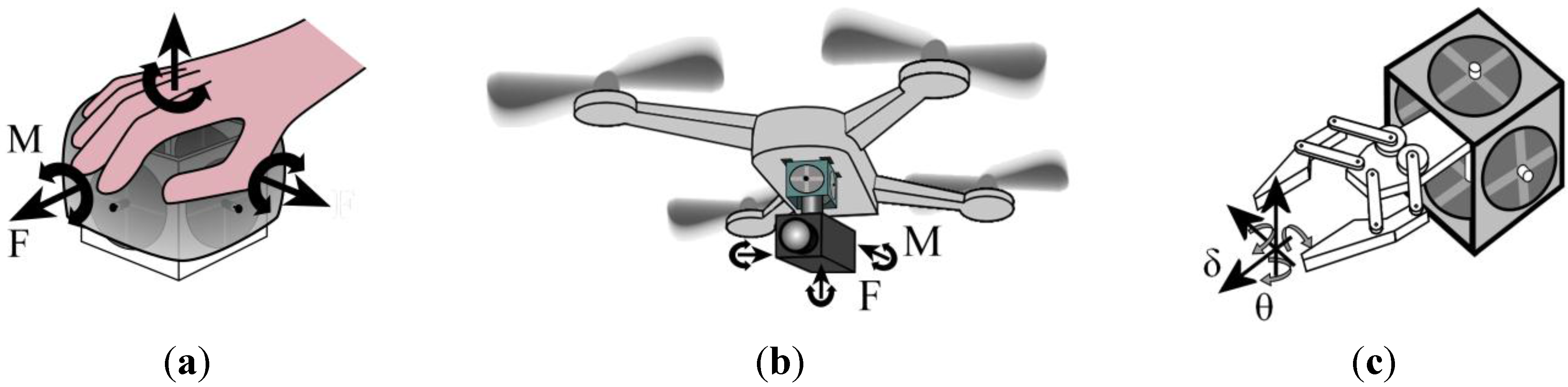
6-DOF actuation from a readily scalable and compact structure enables the cube DEA to potentially be developed for several applications. It can be utilised as a compact haptic device with 6-DOF force, F, and moment, M, output by fitting a thin shell onto the outside of the cross-rod end effector, as shown in Figure 1a. The capacity for each DEA membrane to self-sense strain [5] to enable user input could be exploited in this haptic device without any additional mechanical complexity. Multi-layered DEA membranes would likely be required to maximize the output values of F and M, but this would not limit the number of kinematically free DOF due the inherent membrane compliance.
The actuation output of the cube DEA can also be applied for active vibration stability, which can be required to stabilise cameras or other optic devices. An example of this is shown in Figure 1b, where the cube DEA is fixed to the body of an autonomous air vehicle and the camera is connected to the centre of the cross-rod end effector. This design could be equally applied to terrestrial or aquatic mobile robots that rely on optical sensory input or any camera mount that might experience multi-axis vibrational disturbances. As with the proposed haptic device application in Figure 1a the DEA membranes could be multi-layered to increase passive stiffness and active output of F and M.
A robotic application of the cube DEA is shown in Figure 1c. Here it is proposed that a 1-DOF gripper mechanism (actuated independently of the cube DEA) is mounted inside the cube frame and attached to the centre of the cross rod, which allows the gripper to be displaced linearly, δ, and rotationally, θ, in 6-DOF. This has a specific benefit over traditional, larger multiple DOF robotic manipulators with applications where there is a significant limitation on the available workspace e.g., machine and pipe inspection/maintenance. However, it should be noted that while the use of monolithic DEA membranes provides notable compactness and inherent compliance, the maximum δ range will be limited compared to conventional multi-component parallel robotic manipulators. In addition, the cube DEA in this work can be fabricated entirely from polymers and non-ferromagnetic electrodes (such as the gel electrode in [13]) so it can potentially be compatible with MRI scanners to facilitate invasive manipulation.
Figure 1.
Example applications for the cube dielectric elastomer actuator (DEA) with six degrees of freedom (6-DOF) output: (a) lightweight haptic device; (b) active vibration stabilisation of camera on a mobile quadrotor robot; (c) 6-DOF manipulator (where grasping mechanism is driven by separate 1-DOF actuator inside cube DEA).

2. Principle of Operation
DEA membranes are elastic capacitors that produce a shape change response when a high electric field (>10 V/μm) is applied. The electrostatic Maxwell pressure, P, produces planar expansion and transverse thickness reduction of the DE membrane. The magnitude of P is proportional to the applied electric field squared [4]:
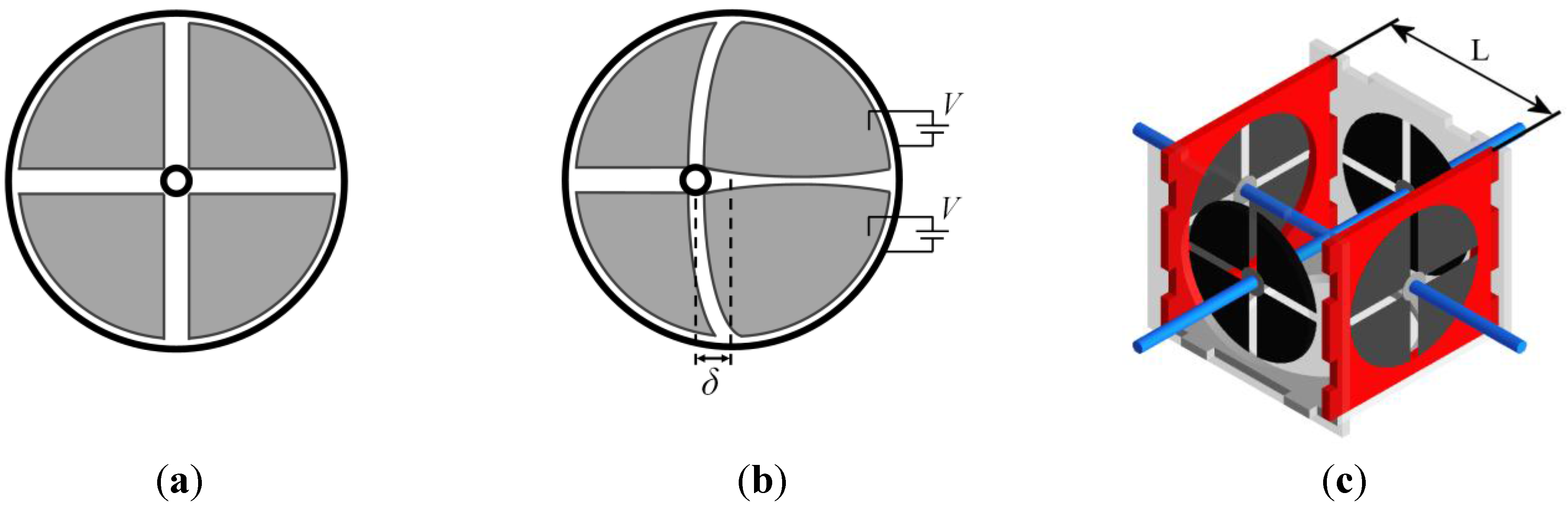
where E is the applied electric field (V/m), ε0 is the permittivity of free space (8.85 × 10⁻¹² F/m) and εr is the relative dielectric constant of the elastomer. An unconstrained DEA membrane produces biaxial actuation strain, so in order to produce a usable output in a specific DOF it is necessary to introduce some form of constraint. This can be achieved by attaching a single membrane to a rigid ring, so that all active strain is directed inwards towards a rigid central inclusion (Figure 2a). Circumferential strain is largely constrained so applying an electric field results in a radial strain that pushes the central effector. By segmenting the electrodes, so that different regions of the membrane can be selectively actuated, 2-DOF actuation is produced by the single membrane (Figure 2b). The actuator concept presented here combines four of these DEA membranes into a cubic frame, with a central cross rod to couple the output of each membrane to an external load (Figure 2c). By independently controlling the response of each electrode quadrant, the cube DEA is capable of producing full 6-DOF actuation.
Figure 2.
Schematic of a single DEA membrane with four electrodes (shaded) in: (a) passive state; and (b) active state with two electrodes actuated producing output displacement, δ. (c) Cube DEA design with the output of four membranes coupled using a cross rod. The characteristic dimension, L, of the cube DEA is the distance between each pair of parallel membranes.

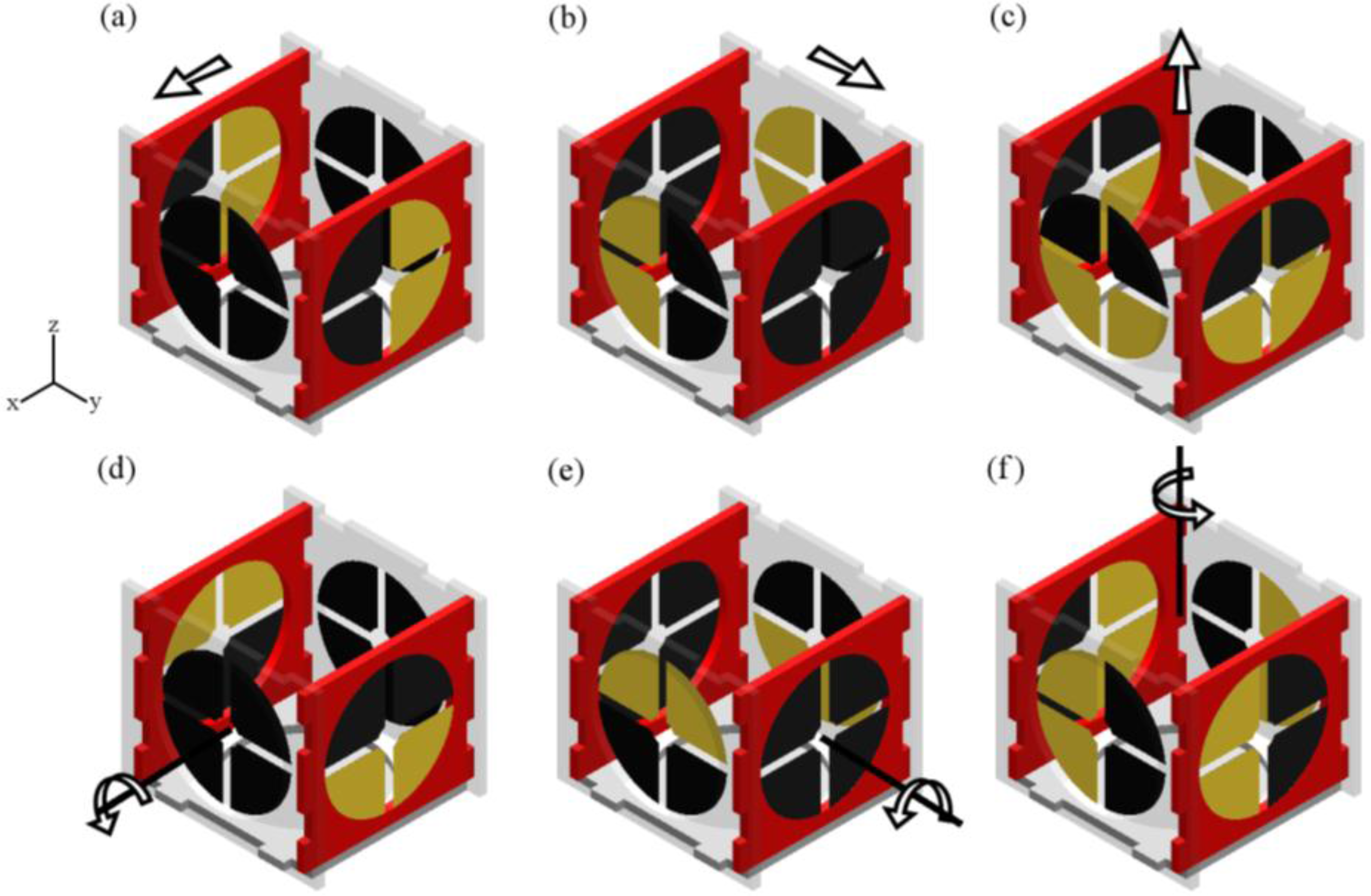
Translational (prismatic) actuation along the x-axis is achieved by activating two membranes that are parallel to the x-z plane as shown in Figure 3a. Similarly, lateral actuation along y-axis is attained by activating two membranes that are parallel to the y-z plane as shown in Figure 3b. Actuation along the z-axis is produced by actuating two electrode quadrants in all four membranes as shown in Figure 3c. Engaging the additional two membranes for z-axis actuation generates twice the force, but does not effect the output displacement since the membranes act in parallel (assuming each membrane has the same thickness and pre-stretch). Equal force output in all three DOF can be achieved by adding an additional two DEA membranes to complete the cube (and modifying the cross rod accordingly). Rotational outputs about each axis are achieved by activating diametrically opposing pairs of electrode segments, as shown in Figure 3d,e,f. As with actuation along the z-axis, rotation about the z-axis incorporates all four membranes being activated (Figure 3f), which will produce twice the torque generated by the other two rotational actuation modes.
An advantage of the cube DEA design is that it produces antagonistic actuation in all 6-DOF (the inherent elasticity of the membrane will provide a return force in any case). By modulating the applied voltage to each electrode quadrant the response magnitude is controlled, as determined by Equation (1). Furthermore, the actuation modes shown in Figure 3 can be combined to produce non-orthogonal outputs.
It should be noted that 6-DOF actuation can be achieved using other electrode configurations than those in Figure 3. Specifically, the orientation of the four electrode quadrants on each membrane can be rotated by 45° (so that only one quadrant per membrane needs to be activated for the outputs in Figure 3) or, alternatively, the number of electrode segments per membrane can be reduced to three (120° circular sectors). The latter configuration represents the most efficient version of the cube DEA in terms of control inputs, since only 12 inputs are required to produce antagonistic actuation in 6-DOF.
Figure 3.
Translational (a,b,c) and rotational (d,e,f) displacement generated by selective activation of electrodes. Active quadrants are highlighted and passive quadrants are black. Note that actuation along and about the x and y axes requires two active DEA membranes (m = 2), while actuation along and about the z axis requires four active DEA membranes (m = 4).

3. Hyperelastic Electro-Mechanical Model
3.1. General DEA Model
In this section, a quasi-static analytical model is derived to predict cube DEA response to an applied voltage. DEA behaviour is well known to be highly non-linear due to the combination of viscous-elastic material properties and the electric field dependent actuation mechanism [14]. In the present study, the model focuses on the hyper-elastic and electro-static components of this behaviour; hence the quasi-static assumption is required to negate viscous effects (as with numerous previous analyses: [15,16,17,18]). Further assumptions, described in Section 3.2, are utilized here to generate a simplified predictive model that can be readily utilized for device prototyping. However, to fully analyze the heterogeneous displacement fields and failure modes of many DEA configurations approaches consider finite deformations have been employed [19,20,21,22,23].
As described in Section 2, the DEA response is produced when an applied electric field generates electrostatic Maxwell pressure, P. The deformation of a thin film elastomer is described by non-dimensional stretch, λ (= length/original length). The principal stretches are considered here to be in-plane stretches λ1 and λ2 and thickness stretch, λ3. The elastomer is assumed to be incompressible (λ1λ2λ3 = 1). The equations of state for an ideal dielectric elastomer are given as [16,17,18,24,25]:
where σ1,2,3 are the true principal stresses, V is the applied voltage (V), T is the nominal membrane thickness (m) and W is the hyperelastic strain energy density. For the DEA material used in this work, 3 M VHB 4905, we assume εr = 4.5 (based on the mean of εr values in [3]).
The Gent strain energy function [26] has previously been applied to model VHB 4905/4910 DEAs since it captures the strain-stiffening behaviour exhibited by the elastomer [16,24,27]. The Gent model is given by:
where µ is the small-strain shear modulus and J is a dimensionless stretch limiting parameter. Applying the Gent model, Equation (4), to the equations of state (2,3) (with the plane stress assumption σ3 = 0) produces Equations (5) and (6) describing general biaxial DEA behaviour:
3.2. Cube DEA Model
The cube DEA is composed of four identical DEA membranes, each with four active quadrants and a rigid central effector (which connects to the cross rod). The membrane is assumed to have principal stretches in the radial, λr, circumferential, λθ and thickness, λt, directions. Each DEA membrane quadrant, when active, will act to apply a radial force to the rigid central effector. Therefore it can be assumed that λr will be greater than λθ during actuation and hence the analytical model of the global membrane behaviour can be approximated by treating λθ as a constant and λr as a dependent variable. This approximation has been applied and experimentally validated in previous analytical models of circular membrane DEAs with rigid central inclusions [15,28], but the assumption of constant λθ limits the applicability of the model to experimental parameters where localized increases of λθ and hence E and P are negligible relative to λr.
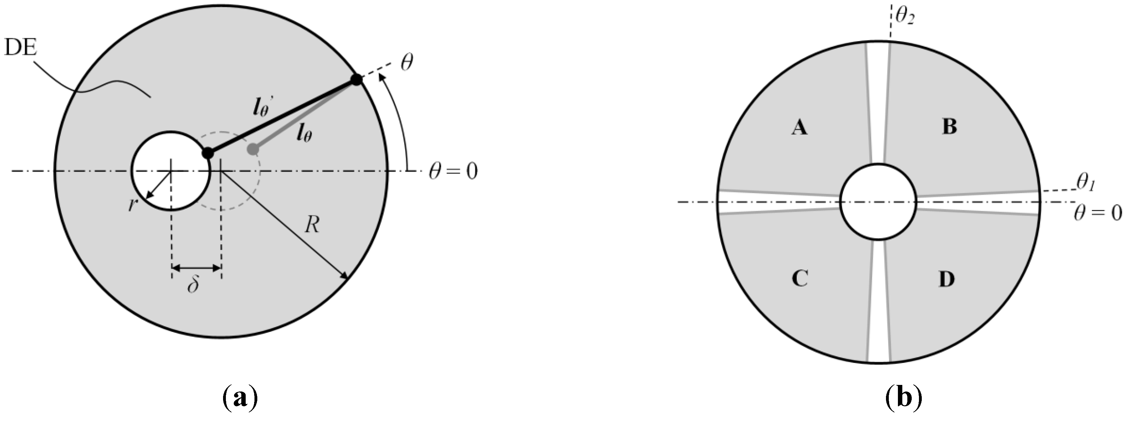
Figure 4 demonstrates how the elastomer length in the first principal axis (radial) changes relative to the actuation displacement, δ. The initial (passive) length, lθ, is given by (R – r) and the actuated length, lθ’, is given by (λr/λr,pre)(R – r), where λr,pre is the pre-stretch applied to the elastomer in the radial direction prior to its attachment to the rigid frame. Hence, λr is described by considering the relation between lθ’ and δ and θ:
The actuation displacement is limited by the physical boundaries of the membrane, (r – R) ≤ δ ≤ (R – r), so the maximum radial stretch is 2λr,pre. Using Equations (5) and (7), the radial stress, σr, can be found for arbitrary values of θ, δ and V. A force component, dF’, acts on the central effector due to σr. dF’ is found by multiplying σr by area, which is equal to an infinitesimal section of the central effector, 2πr(dθ/2π), multiplied by the deformed thickness, T/λrλθ, of the elastomer:
Figure 4.
(a) Representation of change in elastomer length, from lθ to lθ’, along the first principal axis (radial) due to output displacement, δ. The elastomer is contained within a rigid boundary with radius R and contains a rigid inclusion with radius r. (b) Electrodes B and D are activated to induce δ and the axis of actuation, and line of symmetry, is the line from θ = 0 to θ = π.

Resolving dF’ into the axis of actuation gives the total force applied from each section of the membrane:
where m is the number of DEA membranes being utilized and Fext is an externally applied load (with the same orientation as the actuation axis of interest). In Equation (9), it is assumed that two electrode quadrants per membrane are active as shown in Figure 2b. One quadrant can be neglected from consideration due to symmetry (the factor of two in each term in Equation (9) accounts for this), so that 0 < θ < Θ1 represents the first passive region, Θ1 < θ < Θ2 represents the active electrode quadrant and Θ2 < θ < π represents the remaining passive region. Hence each electrode quadrant is assumed to be equal to (Θ2 – Θ1), which for the design presented in this work will be slightly less than 90° due to the passive gaps between quadrants. Note that if different electrode geometries are used or if non-equal voltages are applied to the active electrode constants, then the integration intervals in Equation (9) must be adapted accordingly and the assumption of symmetry about the plane of axis of actuation may no longer hold. For linear actuation along the x and y-axes, Equation (9) is numerically solved for a state of equilibrium with m = 2 (see Figure 3a,b), assuming single layers DEAs. Similarly, for linear actuation along the z-axis, Equation (9) is solved with m = 4 (see Figure 3c), assuming single layers DEAs. To predict rotational actuation, Equation (10) includes an additional design constant, the cube length halved, L/2, to convert membrane force into a moment:
where Mext is an externally applied load (with the same orientation as the actuation rotation of interest). For rotational actuation about the x and y-axes, m = 2 (see Figure 3d,e), and about the z-axis, m = 4 (Figure 3f). It is assumed in Equations (9) and (10) that the cross rod is kinematically free to slide and rotate through the rings attached to each membrane, whereas in practice friction may contribute an additional force. Equations (9) and (10) were numerically solved in Matlab (Mathworks) to predict performance of the prototype cube DEA described in Section 4 (r = 5 mm, R = 25 mm, L = 30 mm, Θ1 = 5°, Θ2 = 85°, µ = 80 kPa, J = 90, λ1,pre = λ2,pre = 3).
4. Materials and Methods
The DEA membranes were fabricated using VHB 4905 polyacrylate tape (3 M) with carbon grease electrodes (MG Chemicals) bonded to a laser cut acrylic frame. The cube frame has a length of 60 mm and the DEA membrane diameter is 50 mm. Four compliant electrode quadrants are applied to each side of the membrane with a passive gap of 3 mm between each electrode segment. Each circular membrane was 3 × 3 biaxially pre-stretched (λr,pre = λθ,pre = 3) prior to being attached to the frame, which resulted in the nominal thickness, T, being reduced from 500 µm to a pre-stretched thickness, λ3T, of 55.6 µm. The maximum applied biaxial stretch before mechanical failure for VHB 4905/4910 has been experimentally determined to be λr,pre = λθ,pre = 36 [29,30]. Therefore, by selecting λr,pre = λθ,pre = 3, and considering that λr ≤ 2λr,pre, the cube DEA should be fail-safe in its passive state.
High voltage drive signals were generated by a Biomimetics Laboratory EAP controller (Auckland Bioengineering Institute, Auckland, New Zealand). Angular displacement was recorded by high resolution camera (Powershot G9, Canon, Tokyo, Japan) and then analysed frame by frame using software (ImageJ) to obtain the maximum displacement. Linear displacement measurements were taken by a laser sensor (LK-G152 and LK-GD500, Keyence) focussed on a flat plastic marker measuring 19 × 11 mm2 fixed to one end of the connecting cross rod, with a sampling rate of 200 Hz. Force measurements were taken using a load cell (LMA-A-10N, Kyowa, Japan) aligned with the flat plastic marker and a signal amplifier (DPM-712B, Kyowa, Japan).
5. Results and Discussion
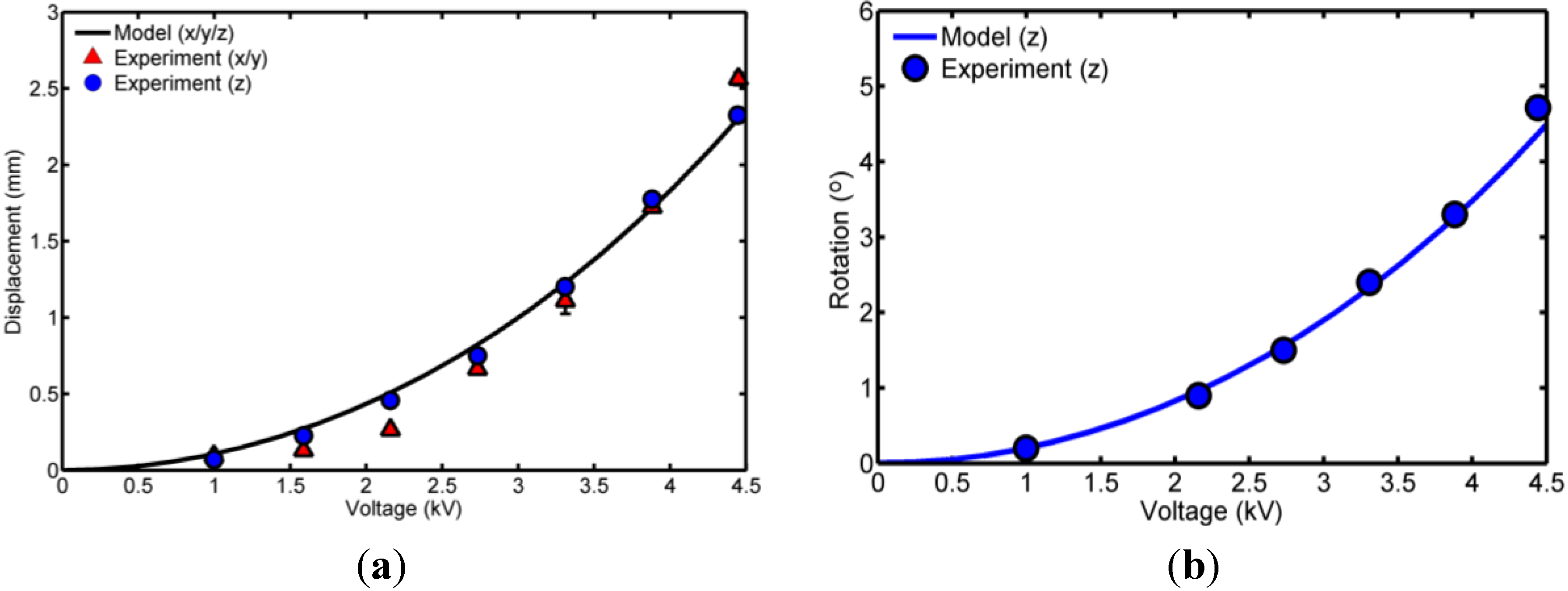
Actuation of a single membrane on the cube DEA (without the cross rod connected) is shown in Figure 5b,c for both single electrode quadrant activation and double electrode quadrant activation. The performance of the cube DEA was then characterised experimentally for the double electrode activation, as described in Section 2 and Section 3. The linear and rotational displacement responses for varying supply voltages are plotted in Figure 6. The dielectric breakdown voltage was found to be around 5.5 kV so 4.5 kV was determined to be a safe working limit for robust actuation and displacement measurements were recorded for supply voltages up to 4.4 kV. The maximum linear displacement in z-axis equalled 2.4 mm and the maximum linear displacement in x-axis equalled 2.6 mm. Note that measurement in the y-axis was not taken as it can be assumed to be identical to the x-axis. As expected, the displacement along the x and y-axes is approximately equal to that of the z-axis, despite the latter utilising twice the number of active electrode quadrants, since the DEA membranes operate in parallel. The results from the analytical model derived in Section 3 are plotted alongside the experimental data in Figure 6. For the rotational displacement the model predicts the response of the non-linear elasticity and electric field-dependent Maxwell stress of the DEA membranes. However, the model does not capture a higher order trend evident in the linear x and y-axis displacement response. The model exhibits an error of 0.24 mm at 2.16 kV and an error of −0.20 mm at 4.45 kV which indicates it is not sufficiently accurate to precisely predict this response along these two DOF. This error is likely attributable to the assumption of homogenous strain along radial lines and hence future work will neglect this assumption by considering finite deformations.
Figure 5.
(a) Cube DEA prototype with 50 mm diameter membranes capable of 6-DOF actuation. Activated membranes shown with single active electrode (b); and with two active electrodes (c).
Figure 5.
(a) Cube DEA prototype with 50 mm diameter membranes capable of 6-DOF actuation. Activated membranes shown with single active electrode (b); and with two active electrodes (c).

Figure 6.
(a) Lateral displacement in x, y and z-axes; and (b) rotational output about z-axis against voltage.
Figure 6.
(a) Lateral displacement in x, y and z-axes; and (b) rotational output about z-axis against voltage.

Although measurements were only taken for positive displacements along each axis, the symmetrical design of the cube DEA means that each output can be antagonistic. Hence the maximum displacements are actually ±2.6 mm for x and y-axis displacement and ±2.4 mm for z-axis displacement at 4.4 kV. These maximum displacement values can be converted to strains relative to the characteristic cube dimension of 60 mm, giving maximum actuation strains of ±4.3% along the x and y-axis and ±4.0% along the z-axis. Figure 6b shows that the maximum rotational displacement measured about z-axis was ±4.8° at 4.44 kV.
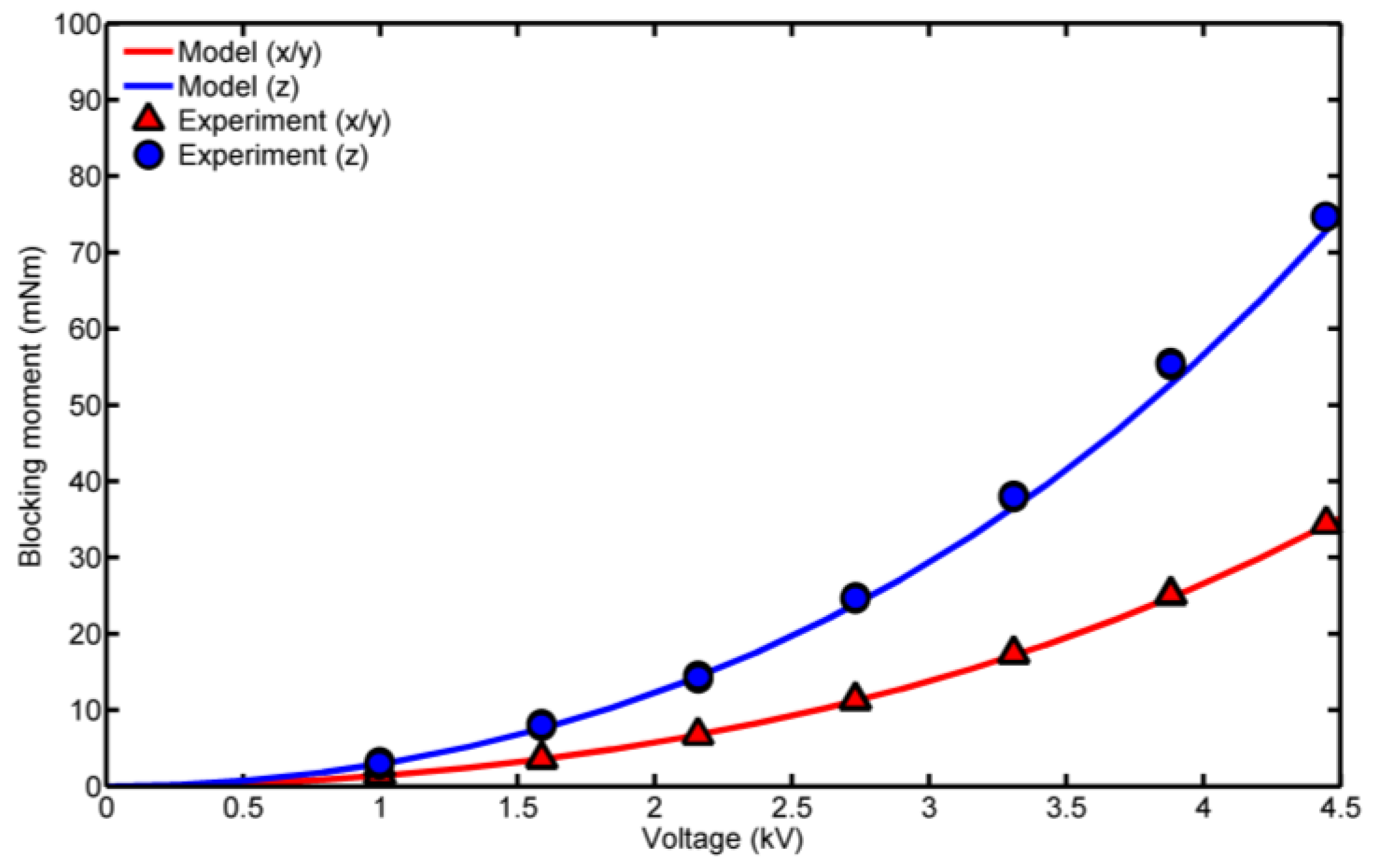
The blocking moment is considered here to be the moment produced with zero output displacement measured about the x and z-axes (again it is assumed that actuation along/about the x and y-axes are identical) with the results are plotted in Figure 7. The maximum blocking moment about the z-axis was ±75.5 mNm at 4.4 kV and the maximum blocking moment about the x-axis was ±34.8 mNm (also at 4.4 kV). As expected, the blocking moment about the z-axis is approximately double that about x and y-axes, since the former utilises twice the number of active electrode quadrants operating in parallel. Also, approximate linear blocking force values can be estimated from the blocking moment measurements since both outputs relate to the sum of forces generated by each DEA membrane at zero displacement and hence the activated DEA membrane equilibrium states are equivalent. Using the experimental moment arm value of 30 mm this gives an estimated linear blocking force along the x axis of 1.16 N and along the z axis of 2.51 N.
It should be noted that because the blocking moment was measured using a load cell pressing against a single arm from the cross rod, the centre of rotation shifted slightly during actuation (two load cells, if available, aligned against two opposing arms from the cross rod would correct this issue). Analysis of video capture suggested that this created a maximum error of 3.7%.
The predicted blocking moment from the analytical model derived in Section 3 is plotted alongside the experimental data in Figure 7 and correlates to the measured blocking moment. However, there is a discrepancy with the numerical and experimental blocking moment about the z-axis at a voltage of over 3 kV. This is likely due to the onset of membrane wrinkling and resulting increase in localized circumferential stretch, λθ. Any increase of λθ will concomitantly increase the electric field and hence P, which will generate a greater blocking moment. Electromechanical membrane wrinkling and increased λ2 is not captured in the current analytical model so is the likely sources of error. In summary the model has been shown to predict the general response but more computationally involved methods such as finite element modelling are required for detailed design.
Figure 7.
Blocking moment generated about each axis against voltage.

The simple structure of the cube DEA means that it is readily scalable. Assuming that r/R and L/R can be maintained at all scales and V and T are constant then as the cube dimensions are reduced (R→0) the actuation will be affected as listed in Table 1. In summary, these scaling relationships show that the displacements and forces in the three linear DOF will both scale proportionally, meaning that performance is likely to scale with the anticipated load. In contrast, the angular displacements and moments in the three rotational DOF scale differently, so the relative displacement/moment performance will change considerably at different scales.

| Output | Scaling Relationship | |
|---|---|---|
| linear displacement, δx,y,z | δx,y,z ∝ 1/R | actuation stretch is dimensionless |
| rotational displacement, φx,y,z | independent of independent of R | actuation stretch is dimensionless |
| blocking force, Fb | Fb ∝ 1/R | Equation (8): dF’ ∝ r and r ∝ R |
| blocking moment, Mb | Mb ∝ 1/R2 | Equation (8): dF’ ∝ r and r ∝ R Equation (10) dF’ ∝ L and L ∝ R |
It is anticipated that future development of the cube DEA will involve utilizing improved DEA materials and increased automation of fabrication. Switching the elastomer material from VHB 4905 to a silicone elastomer will greatly reduce the viscoelasticity and creep behaviour of the membrane [3,31]. This is particularly important for active vibration damping applications, where a large viscous component will inhibit high frequency response. However, silicone elastomer DEAs described in literature to date have not generated actuation strains equal to VHB 4905/4910. In addition, silicone elastomer films are more readily fabricated as multi-layered stacks using techniques such as spin coating [32] or spray deposition [33]. Such fabrication methods can enable the development of heterogeneous DE microstructures, which have been numerically demonstrated to significantly amplify the electromechanical coupling [22]. The polymeric composition of the cube DEA means that it could ultimately be fabricated using 3D printing techniques (as demonstrated by [34]). The potential 3D printed devices would open the possibility for a network of inter-connected cube DEAs to be embedded within a structure for novel morphing capabilities or active vibration damping. An important consideration for the cube DEA to be developed for practical applications where the external loading may be unpredictable are instabilities such as pull-in failure that are associated across various configurations of DEAs [35,36,37].
6. Conclusion
A novel 6-DOF polymer actuator has been presented that utilises highly compliant dielectric elastomer membranes. The inherent compliance and elasticity of membranes allows the single cross-shaped component to be coupled to multiple inputs, effectively unifying the numerous discrete components required in previous multi-DOF actuator devices. An electro-mechanical model has been developed using the Gent hyperelastic strain energy function, which is able to accurately predict actuator displacement. Experimental testing of a prototype 6-DOF device with characteristic length of 60 mm demonstrated maximum displacements of ±2.6 mm (±4.3%) and ±4.8° and a maximum blocking moment of ±75.5 mNm. The capacity for full 6-DOF actuation from a compact and easily fabricated polymeric package enables implementation in a range of applications such as robotics and active vibration damping.
Acknowledgements
The authors would like to thank the Department of Mechanical Engineering, University of Bristol for supporting this work.
Author Contributions
Pengchuan Wang developed the actuator concept, performed the experiments and wrote the initial text. Andrew Conn was the principal investigator of this work, oversaw its progress and prepared the final draft for submission.
Conflicts of Interest
The authors declare no conflict of interest.
References
- Anderson, I.A.; Tse, T.C.H.; Inamura, T.; O’Brien, B.M.; McKay, T.; Gisby, T. A soft and dexterous motor. Appl. Phys. Lett. 2011, 98. [Google Scholar] [CrossRef]
- Bar-Cohen, Y. Electroactive Polymer (EAP) Actuators as Artificial Muscles, 2nd ed.; SPIE Press: Bellingham, WA, USA, 2004. [Google Scholar]
- Brochu, P.; Pei, Q. Advances in dielectric elastomers for actuators and artificial muscle. Macromol. Rapid Commun. 2010, 31, 10–36. [Google Scholar] [CrossRef] [PubMed]
- Pelrine, R.; Kornbluh, R.; Pei, Q.; Joseph, J. High-speed electrically actuated elastomers with strain greater than 100%. Science 2000, 287, 836–839. [Google Scholar] [CrossRef] [PubMed]
- Jung, K.; Kim, K.J.; Choi, H.R. A self-sensing dielectric elastomer actuator. Sens. Actuators A Phys. 2008, 143, 343–351. [Google Scholar] [CrossRef]
- Jhong, Y.; Mikolas, D.; Yeh, T.; Fang, W.; Shaw, D.; Chen, J.; Fu, C. Characterization of nonlinear effects in a two-dimensional dielectric elastomer actuator. Smart Mater. Struct. 2010, 19. [Google Scholar] [CrossRef]
- Jordan, G.; McCarthy, D.N.; Schlepple, N.; Krißler, J.; Schroder, H.; Kofod, G. Actuated micro-optical submount using a dielectric elastomer actuator. IEEE/ASME Trans. Mechatron. 2011, 16, 98–102. [Google Scholar] [CrossRef]
- Pei, Q.; Rosenthal, M.; Stanford, S.; Prahlad, H.; Pelrine, R. Multiple-degrees-of-freedom electroelastomer roll actuators. Smart Mater. Struct. 2004, 13, N86–N92. [Google Scholar] [CrossRef]
- Choi, H.R.; Jung, K.M.; Kwak, J.W.; Lee, S.W.; Kim, H.M.; Jeon, J.W.; Nam, J.D. Digital polymer motor for robotic applications. In Proceedings of the IEEE International Conference on Robotics and Automation, Taipei, Taiwan, 14–19 September 2003; pp. 1857–1862.
- Conn, A.T.; Rossiter, J.M. Towards holonomic electro-elastomer actuators with six degrees of freedom. Smart Mater. Struct. 2012, 21. [Google Scholar] [CrossRef]
- Koo, J.C.; Choi, H.R.; Jung, M.Y.; Jung, K.M.; Nam, J.D.; Lee, Y.K. Design and control of three-DOF dielectric polymer actuator. Key Eng. Mater. 2005, 297–300, 665–670. [Google Scholar] [CrossRef]
- Stewart, D. A platform with six degrees of freedom. Proc. Inst. Mech. Eng. Part 1 1965, 180, 371–386. [Google Scholar] [CrossRef]
- Rossiter, J.; Yap, B.; Conn, A. Biomimetic chromatophores for camouflage and soft active surfaces. Bioinspir. Biomim. 2012, 7, 1–10. [Google Scholar] [CrossRef] [PubMed]
- Sarban, R.; Jones, R.W. Physical model-based active vibration control using a dielectric elastomer actuator. J. Intell. Mater. Syst. Struct. 2012, 23, 473–483. [Google Scholar] [CrossRef]
- Berselli, G.; Vertechy, R.; Vassura, G.; Parenti-Castelli, V. Optimal synthesis of conically shaped dielectric elastomer linear actuators: Design methodology and experimental validation. IEEE/ASME Trans. Mechatron. 2011, 16, 67–79. [Google Scholar] [CrossRef]
- Huang, R.; Suo, Z. Electromechanical phase transition in dielectric elastomers. Proc. R. Soc. A 2012, 468, 1014–1040. [Google Scholar] [CrossRef]
- Kofod, G. The static actuation of dielectric elastomer actuators: How does pre-stretch improve actuation? J. Phys. D Appl. Phys. 2008, 41. [Google Scholar] [CrossRef]
- Lu, T.; Huang, J.; Jordi, C.; Kovacs, G.; Huang, R.; Clarke, D.R.; Suo, Z. Dielectric elastomer actuators under equal-biaxial forces, uniaxial forces, and uniaxial constraint of stiff fibers. Soft Matter 2012, 8, 6167–6173. [Google Scholar] [CrossRef]
- Dorfmann, A.; Ogden, R.W. Nonlinear electroelasticity. Acta Mech. 2005, 174, 167–183. [Google Scholar] [CrossRef]
- McMeeking, R.M.; Landis, C.M. Electrostatic forces and stored energy for deformable dielectric materials. J. Appl. Mech. 2005, 72, 581–590. [Google Scholar] [CrossRef]
- Bertoldi, K.; Gei, M. Instabilities in multi-layered soft dielectrics. J. Mech. Phys. Solids 2011, 59, 18–42. [Google Scholar] [CrossRef]
- Rudykh, S.; Lewinstein, A.; Uner, G.; deBotton, G. Analysis of microstructural induced enhancement of electromechanical coupling in soft dielectrics. Appl. Phys. Lett. 2013, 102. [Google Scholar] [CrossRef]
- Suo, Z.; Zhao, X.; Greene, W.H. A nonlinear field theory of deformable dielectrics. J. Mech. Phys. Solids 2008, 56, 467–486. [Google Scholar] [CrossRef]
- Zhu, J.; Kollosche, M.; Lu, T.; Kofod, G.; Suo, Z. Two types of transitions to wrinkles in dielectric elastomers. Soft Matter 2012, 8, 8840–8846. [Google Scholar] [CrossRef]
- Plante, J.S.; Dubowsky, S. On the performance mechanisms of dielectric elastomer actuators. Sens. Actuators A Phys. 2007, 137, 96–109. [Google Scholar] [CrossRef]
- Gent, A.N. A new constitutive relation for rubber. Rubber Chem. Technol. 1996, 69, 59–61. [Google Scholar] [CrossRef]
- Conn, A.T.; Rossiter, J. Harnessing electromechanical membrane wrinkling for actuation. Appl. Phys. Lett. 2012, 101. [Google Scholar] [CrossRef]
- Conn, A.T.; Pearson, M.J.; Pipe, A.G.; Welsby, J.; Rossiter, J. Dielectric elastomer vibrissal system for active tactile sensing. Proc. SPIE 2012, 8340. [Google Scholar] [CrossRef]
- Kofod, G. Dielectric elastomer actuators. Ph.D. Thesis, Department of Chemistry, The Technical University of Denmark, Lyngby, Denmark, 2001. [Google Scholar]
- Sommer-Larsen, P.; Kofod, G.; Shridhar, M.H.; Benslimane, M.; Gravesen, P. Performance of dielectric elastomer actuators and materials. Proc. SPIE 2002, 4695, 158–166. [Google Scholar]
- Michel, S.; Zhang, X.Q.; Wissler, M.; Lowe, C.; Kovacs, G. A comparison between silicone and acrylic elastomers as dielectric materials in electroactive polymer actuators. Polym. Int. 2009, 59, 391–399. [Google Scholar] [CrossRef]
- Lotz, P.; Matysek, M.; Schlaak, H.F. Fabrication and application of miniaturized dielectric elastomer stack actuators. IEEE/ASME Trans. Mechatron. 2011, 16, 58–66. [Google Scholar] [CrossRef]
- Araromi, O.A.; Conn, A.T.; Ling, C.S.; Rossiter, J.M.; Vaidyanathan, R.; Burgess, S.C. Spray deposited multilayered dielectric elastomer actuators. Sens. Actuators A Phys. 2011, 167, 459–467. [Google Scholar] [CrossRef]
- Rossiter, J.; Walters, P.; Stoimenov, B. Printing 3D dielectric elastomer actuators for soft robotics. Proc. SPIE 2009, 7287. [Google Scholar] [CrossRef]
- Plante, J.-S.; Dubowsky, S. Large-scale failure modes of dielectric elastomer actuators. Int. J. Solids Struct. 2006, 43, 7727–7751. [Google Scholar] [CrossRef]
- Rudykh, S.; Bhattacharya, K.; deBotton, G. Multiscale instabilities in soft heterogenous dielectric elastomers. Proc. R. Soc. A 2015, 470. [Google Scholar] [CrossRef]
- Zhao, X.; Suo, Z. Method to analyze electromechanical stability of dielectric elastomers. Appl. Phys. Lett. 2007, 91. [Google Scholar] [CrossRef]
© 2015 by the authors; licensee MDPI, Basel, Switzerland. This article is an open access article distributed under the terms and conditions of the Creative Commons Attribution license (http://creativecommons.org/licenses/by/4.0/).
Share and Cite
MDPI and ACS Style
Wang, P.; Conn, A.T. Elastic Cube Actuator with Six Degrees of Freedom Output. Actuators 2015, 4, 203-216. https://doi.org/10.3390/act4030203
AMA Style
Wang P, Conn AT. Elastic Cube Actuator with Six Degrees of Freedom Output. Actuators. 2015; 4(3):203-216. https://doi.org/10.3390/act4030203
Chicago/Turabian StyleWang, Pengchuan, and Andrew T. Conn. 2015. "Elastic Cube Actuator with Six Degrees of Freedom Output" Actuators 4, no. 3: 203-216. https://doi.org/10.3390/act4030203