Abstract
Levee failure due to nappe flow and subsequent erosion presents a significant challenge to flood protection infrastructure. This study evaluates the effectiveness of horizontal drainage layers, a common seepage control method, in mitigating these risks. While many traditional solutions to mitigate overtopping are costly and complex, horizontal drainage layers offer a promising and cost-effective alternative. These layers not only address seepage control but also manage nappe flow-induced erosion, potentially reducing construction and maintenance costs. Despite extensive research on their role in seepage control, a gap remains in understanding their effectiveness against overtopping-induced erosion, particularly in managing reverse flow. Existing studies often address seepage control or nappe flow erosion separately, overlooking the integrated impact of these layers. This study aims to address this gap by evaluating the performance of horizontal drainage layers under simulated overtopping conditions. The research involves two series of experiments, Series I: Focuses on newly built levees equipped with full (HD15L50 and HD25L50, where the thicknesses are 15 and 25 cm, respectively, with a horizontal drainage layer length of 50 cm and a crest length of 40 cm), partial length (HD15L40 and HD25L40), and short/reduced length (HD15L30 and HD25L30). The results showed that full-length layers reduce erosion inside the levee body and foundation by almost 100% and enhance levee stability due to their superior ability to dissipate hydraulic energy. Series II: Investigates practical solutions for retrofitting existing levees using shorter drainage layers with extended crests and gauzed sheets (HD15L15L30C60GH and HD25L30C60GH, where the thicknesses are 15 and 25 cm, the drainage length is 30 cm, and the crest is extended to 60 cm with gauzed sheets). Although shorter layers were less effective than full-length ones, extending the levee crest significantly improved their performance, achieving protection levels comparable to full-length layers, providing a valuable solution for upgrading existing levees. Overall, this study offers valuable insights by systematically evaluating and optimizing seepage control techniques. These findings can be directly applied to guide levee design, maintenance, and risk reduction strategies. This research contributes significantly to improving the resilience of levee systems against water pressure and ensuring their long-term stability.
1. Introduction
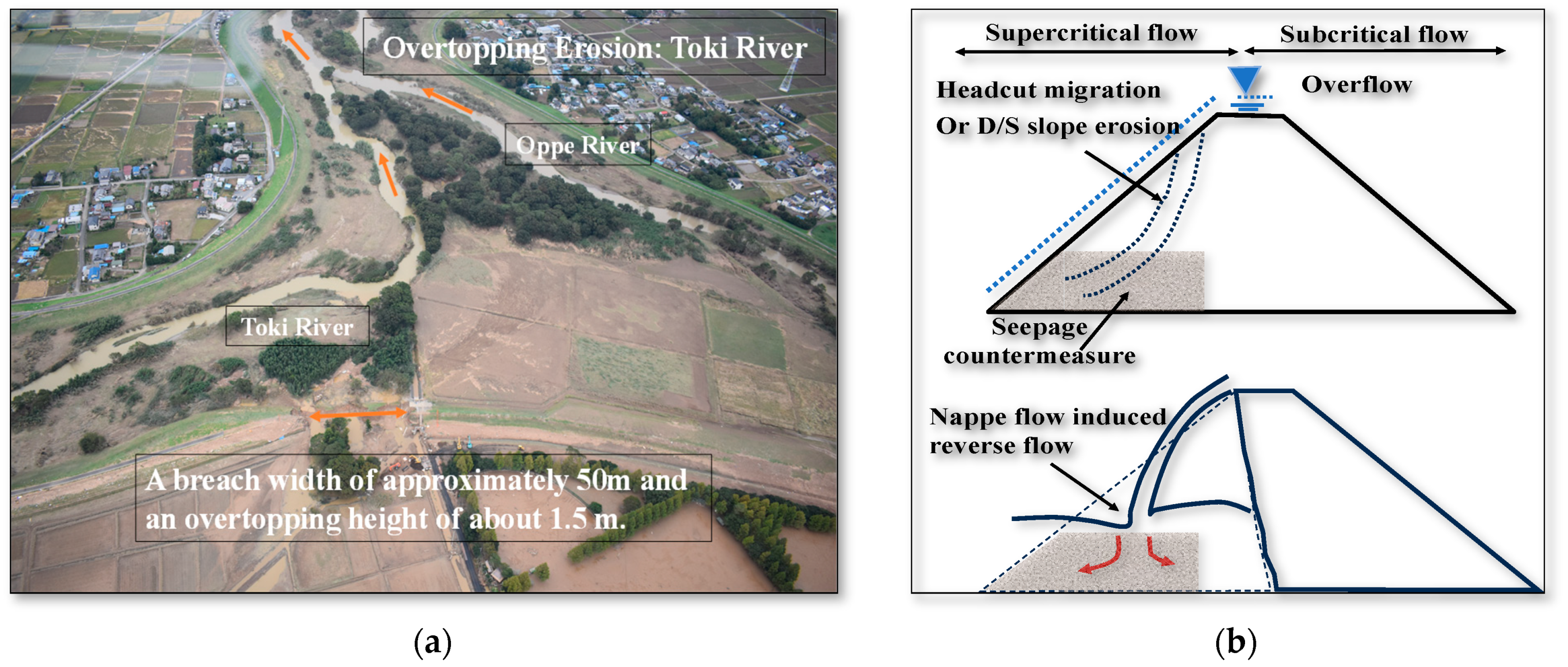
Levees are critical structures for flood protection, yet they are vulnerable to erosion caused by seepage, overtopping, and nappe flow-induced reverse flow, which can compromise the integrity of levees. During Typhoon Hagibis (Typhoon No. 19) in 2019, several breaches occurred due to overtopping, leading to significant flooding in multiple locations [1,2,3]. The overtopping erosion caused many types of failures, which could start from the top, bottom, or center of the inner slope of the levees [4]. Specifically, overtopping erosion was identified as a primary cause of these breaches. Figure 1a shows specific sites along the Toki River in Japan where overtopping erosion led to breaches and flooding. Nappe flow is a type of overtopping erosion failure that typically starts from the bottom of the inner slope of the levee or at the toe of the levee. When floodwaters spill over the crest of a levee, they form scour holes near the downstream toe. These scour holes then progress towards the crest, leading to nappe flow. This flow impinges directly on the downstream area, causing a reverse flow towards the levee body and resulting in headcut erosion or the breach of the levee body. The schematic of the above phenomenon has been shown in Figure 1b. Therefore, nappe flow represents a bottom-initiated overtopping erosion failure. Nappe flow has been identified as a critical factor contributing to levee erosion and failure [5,6,7,8,9]. To address this crucial issue, horizontal drainage layers have been proposed as an effective countermeasure against nappe flow-induced reverse flow. These layers, while traditionally used for seepage control, have the potential to mitigate the erosive effects of overtopping by dissipating hydraulic energy and preventing the formation of scour holes.

Figure 1.
Overtopping levee erosion: (a) aerial view of levee breach by overtopping erosion at Toki River; (b) schematic of the formation of nappe flow after levee overtopping.
Several studies have investigated various measures to mitigate overtopping and nappe flow-induced erosion, including the use of geogrids and vegetation. Abbas and Tanaka 2022 [7] investigated a method in which the scouring induced due to the nappe flow was reduced using a combination of geogrid reinforcements and pooled water. The study by Dissanayaka et al. [8] found that the orientation and presence of vegetation on the levee crest significantly reduce downstream energy, enhancing erosion control and levee stability. Pan et al. [10], Chanson [11], and Wahl [12] proposed different slope protection measures to mitigate overtopping and nappe flow. Al-Riffai [13] proposed using a downstream rockfill berm as a protection method to reduce erosion and delay breach formation in overtopped noncohesive earthen levees. Powledge et al. [14] found that increasing compaction effort from 95% to 103% of the standard proctor value in a cohesive clay dike reduces empty pores and delays matric suction reduction and breach development. Powledge et al. [15,16] conducted large-scale lab and field tests to evaluate breaching mechanisms, dividing the erosion regime into three zones based on water flow velocity. They found that the rate of erosion depends on numerous factors, including levee configuration, maximum flow velocity, and voids in the slope. The impact of nappe flow erosion on levee stability has been observed in several case studies, including the levee failures during Hurricane Katrina in New Orleans [17]. Numerical modeling efforts have also been undertaken to understand the breaching mechanisms and parameters associated with nappe flow erosion in earth dams and levees [18]. Zhu et al. [19] described the erosion process of levees, highlighting how overflow water impacts erosion and the subsequent collapse of soil blocks and breaches. Shinohara et al. [20] discussed the effectiveness of reinforcement technology in preventing levee crest overtopping, highlighting methods that enhance levee stability and reduce the risk of overtopping during flood events. Yoshimori et al. [21] demonstrated that installing sheet piles on the downstream side of a levee effectively prevents erosion of the downstream shoulder. Their experiments showed that extensive erosion control measures with sheet piles are effective in preventing overflow erosion. Johnson et al. [22] studied the impact of overtopping storm waves on levee scours and evaluated various countermeasures, such as revetments and geotextiles, to enhance levee protection. While these measures [7,8,9,10,11,12,13,14,15,16,17,18,19,20,21,22] are effective, they can be costly and difficult to implement on a large scale.
Horizontal drainage layers, on the other hand, offer a more practical solution due to their dual functionality in both seepage control and erosion mitigation. Seepage flow through the levee body can contribute to internal erosion processes and potentially intensify the effects of nappe flow and overtopping [23]. Seepage flow can lead to the development of concentrated leak erosion tunnels within the levee body, compromising its structural integrity [24,25]. The study by Locci-Lopez and Lorenzo [26] investigates the impact of seepage-induced pore pressure variations beneath an earthen levee using an innovative seismic tool. To mitigate these issues, horizontal drainage layers have been employed as a seepage control measure in levee design and rehabilitation [27,28]. Sazzad and Islam [29] found that horizontal drainage layers are highly effective in reducing seepage pressures within earth dams, thereby enhancing their overall stability and preventing potential failures. The U.S. Army Corps of Engineers (USACE) reports emphasize that horizontal drainage layers are highly effective in reducing seepage pressures and enhancing the stability of levees and dams. These layers work by intercepting and redirecting seepage water away from critical areas, thereby preventing erosion and maintaining structural integrity [30,31].
Many proposed solutions to mitigate the risks associated with overtopping are both costly and challenging to implement. Horizontal drainage layers, however, offer a promising and cost-effective alternative. Already widely used for seepage control in levees, these layers can potentially be repurposed to manage nappe flow and reverse flow erosion, thereby avoiding additional costs and complexity in levee construction and maintenance. Although extensive research has been conducted on the role of horizontal drainage layers in controlling seepage within levees and dams, a significant gap remains in understanding their effectiveness in preventing erosion caused by overtopping, particularly nappe flow-induced reverse flow. Existing studies have focused largely on individual aspects of seepage control or nappe flow erosion without addressing the integrated impact of these drainage layers on both issues simultaneously.
This study aims to address this gap by systematically evaluating the performance of horizontal drainage layers under simulated overtopping conditions. By investigating how these drainage layers can be effectively used not only for seepage control but also for protecting against nappe flow-induced erosion, this research seeks to provide comprehensive guidelines for their application. Ultimately, this study enhances the resilience of both new and existing levees, making their design and maintenance more efficient, practical, and cost-effective. By integrating seepage control with erosion prevention, this research will contribute valuable insights into improving levee stability and reducing the risks associated with overtopping events.
2. Materials and Methodology
2.1. Experimental Setup and Test Configurations
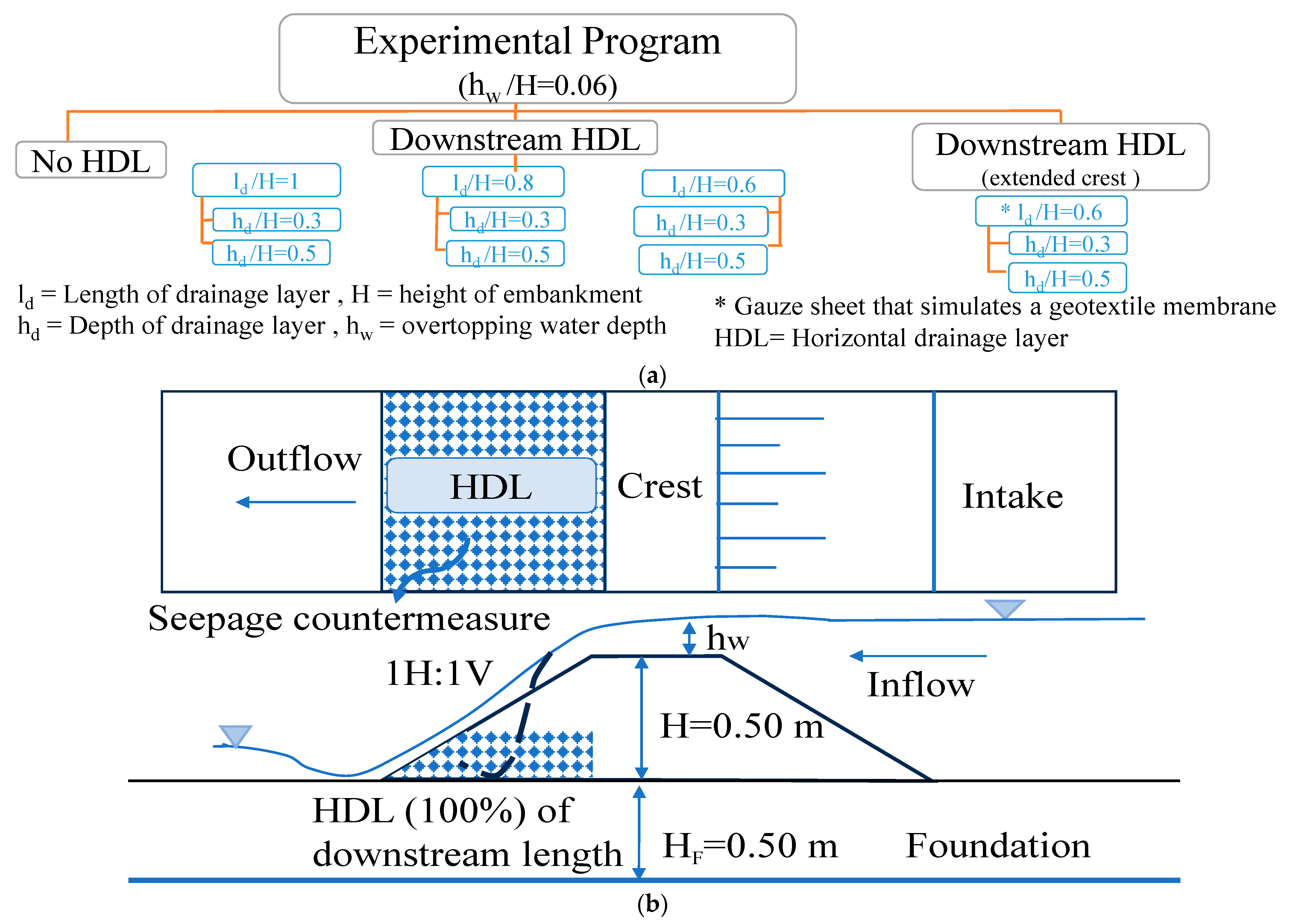
The experimental setup aimed to simulate conditions conducive to nappe flow-induced reverse flow and evaluate the effectiveness of various seepage countermeasures in mitigating erosion along levees. The flow chart of the experimental program is shown in Figure 2a, and the schematic diagram of the setup is shown in Figure 2b. A levee body with a height of 50 m, a top width of 40 cm (extended to 60 cm in Series II configurations), as illustrated in Figure 2c, and a downstream slope of 1:1 was constructed to replicate nappe flow. The foundation, with a height of 50 cm and a length of 140 cm, was installed in a deep flume, measuring 6.5 m in length, 0.5 m in width, and 1.2 m in depth, as depicted in the experimental setup in Figure 3a. These dimensions were selected based on a geometric scale of 1/10, ensuring that the model accurately reflects the key hydraulic conditions of real-world levees, particularly those observed during the Kinugawa River flood event in 2015. The model levee height of 50 cm corresponds to a prototype height of approximately 5 m. This height aligns well with the real levee heights at the Kinugawa River in Ibaraki Prefecture and the Oppegawa River in Saitama Prefecture, Japan, where levee heights range between 3 and 5 m at different locations. Although small-scale models may not capture every detail of the phenomenon, they are often preferred over full-scale models due to faster result observation and lower costs [32]. This setup allowed for a controlled replication of hydraulic conditions relevant to levee environments, balancing laboratory manageability with the need to replicate key hydraulic and erosion behaviors. The chosen scale ensures that the hydraulic phenomena observed in the experiments are representative of actual levee failures.


Figure 2.
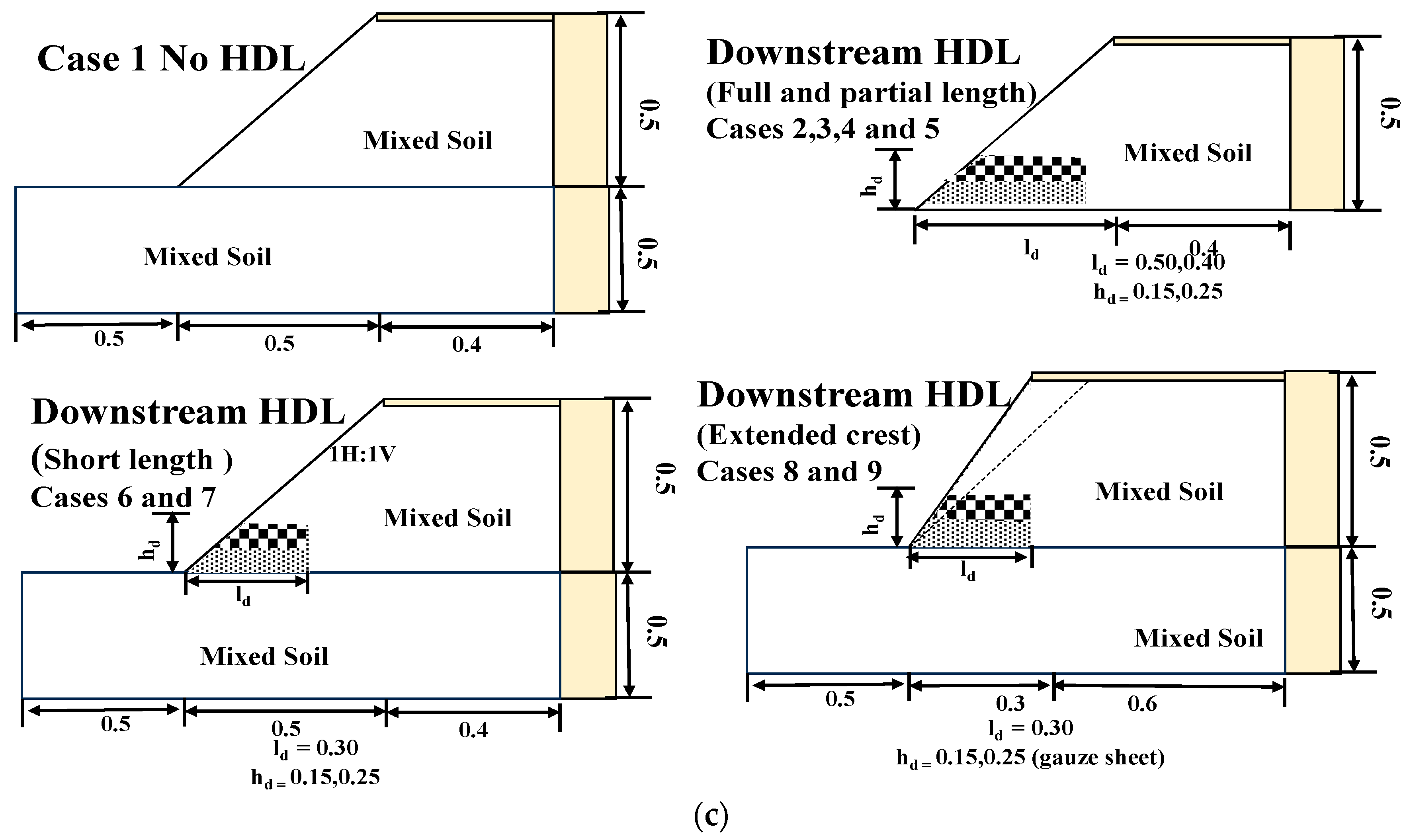
A comprehensive overview of the experimental framework: (a) flow chart of the experimental program; (b) schematic diagram of the experimental setup; (c) configurations of different experimental cases.

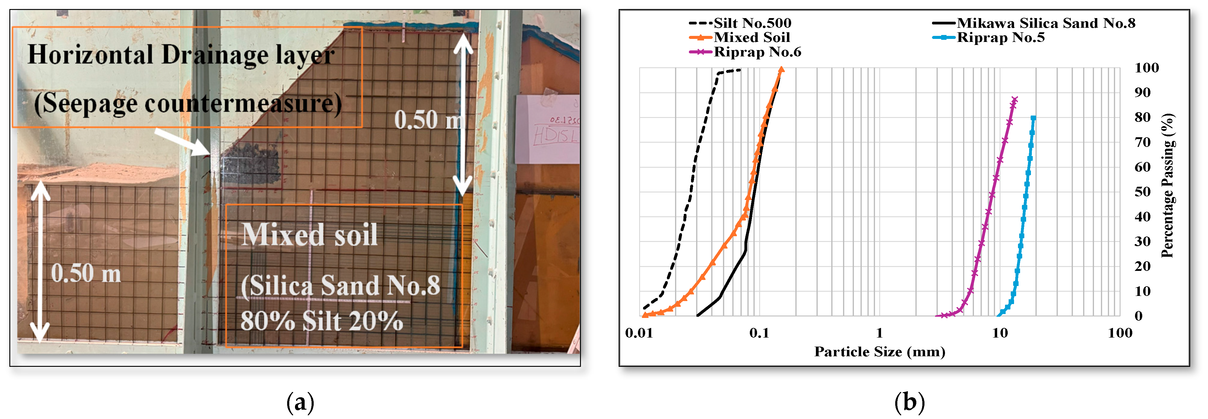
Figure 3.
Laboratory experimental setup and sieve analysis: (a) Experimental setup in the laboratory; (b) sieve analysis of levee materials (Mikawa Silica sands) and drainage layer riprap materials.
The experimental configurations, as illustrated in Figure 2c and listed in Table 1, included the following scenarios to evaluate the effectiveness of seepage countermeasures. Figure 2a,c and Table 1 provide a visual representation of these configurations, detailing the variations with no drainage, with horizontal drainage (having length of drainage layer to the height of levee ratios 1, 0.8, and 0.6, respectively), and with horizontal drainage combined with an extended crest.

Table 1.
Nappe flow erosion experimental cases (all the cases were conducted under mixed soil: 80% Mikawa Silica sand No. 8 and 20% silt).
Control Case with No Horizontal Drain (CCNHD).
The initial configuration served as a baseline, representing a scenario without any specific seepage control measures, simulating unprotected levee conditions.
Full-Length Horizontal Drainage Layers (HD15L50 and HD25L50).
Two configurations of full-length horizontal drainage layers were assessed: HD15L50 and HD25L50, differing in thickness (15 cm and 25 cm, respectively) and extending the entire length of the downstream slope of the levee. These configurations aimed to assess the comprehensive protection provided by continuous drainage layers against both foundation and levee body scour.
Partial/Short-Length Horizontal Drainage Layers (HD15L40 and HD25L40).
Partial-length drainage layers were evaluated with lengths reduced to 40 cm while maintaining the same thickness variations as in the full-length configurations (15 cm and 25 cm). These configurations were included to evaluate the efficacy of shorter drainage layers in mitigating erosion, focusing on the internal stability of the levee body.
Reduced-Length Horizontal Drainage Layers (HD15L30 and HD25L30).
Further reductions in length to 30 cm were evaluated under similar thickness variations (15 cm and 25 cm) to investigate the minimal length required for effective erosion control. These configurations aimed to determine the threshold at which horizontal drainage layers might become ineffective in preventing scouring.
Extended Crest Length with Gauzed Sheets (HD15L30C60GH and HD25L30C60GH).
To simulate practical modifications for existing levees, configurations with extended crest lengths of 60 cm were evaluated. This setup aimed to replicate the protective benefits of longer drainage layers without extensive structural modifications. Additionally, gauzed sheets were incorporated into selected configurations (HD15L30C60GH, HD25L30C60GH) to assess their impact on preventing clogging and maintaining drainage efficiency.
2.2. Soil Parameters and Materials
The levee was created by compacting mixed soil consisting of Silica sand No. 8 (Mikawa Silica Co., Ltd., Japan) with a median grain size (d50) of 0.095 mm and silt (Marunaka Hakuto Co., Ltd., Japan.) with a d50 of 0.025 mm. The mixing ratio of silica sand to silt was 8:2 by weight. The optimum moisture content for the mixed soil was 18.2%. The levee body and foundation were compacted to 90% of the maximum dry density using a hammer, with each 5 cm layer receiving 6 blows, achieving the desired compaction [23,33].
The horizontal drainage layers were composed of rip rap materials from Konan Co., Ltd.Japan, specifically Rip rap No. 5 with a d50 of 16.41 mm and Rip rap No. 6 with a d50 of 8.48 mm, chosen for their ability to withstand hydraulic forces and resist erosion. The dimensions of the drainage layers were set according to the following criteria: The minimum thickness of the horizontal drainage layer was 18 inches. The horizontal layer extended from the downstream toe of the levee inward, covering a distance varying from 25% to 100% of the distance from the toe to the centerline of the levee [34,35,36]. Sieve analysis for levee materials and drainage layer materials has been shown in Figure 3b.
2.3. Hydraulic Conditions and Experimental Procedure
Hydraulic conditions were set to maintain a constant flow rate to the outer side of the levee, ensuring an overtopping water depth of 3 cm at the center of the crest (equivalent to approximately 30 cm at the actual site under the 1/10 scale). This scale was chosen to replicate critical hydraulic phenomena such as overtopping depth and flow velocity, which are vital for studying erosion processes. In this model, the overtopping depth of 3 cm corresponds to a prototype overtopping depth of 30 cm, which accurately reflects the overtopping conditions observed during the Kinugawa River flood event, where overtopping depths were reported between 20 and 50 cm [37,38]. To investigate the mechanism of erosion and destruction on the backside of the river, a fixed bed was installed upstream from the shoulder of the river slope, and a moving bed made of sandy soil was installed downstream. The Levee crest was simulated as a rigid pavement by placing a 1.2 cm thick wooden plank. Previous studies such as Shinohara et al. [39] have concluded that when nappe flow occurs on the levee top, the toe scours, causing the collapse of the levee body and further erosion. To suppress the break of the top pavement, it is effective to strengthen the pavement with grid material.
2.4. Scaling Principles and Methods
This study utilized a geometric scale of 1/10 to model the prototype levee, ensuring that all linear dimensions in the experimental model were scaled down by a factor of 10. To maintain dynamic similarity, Froude similarity was applied, ensuring that the ratio of inertial to gravitational forces remained consistent between the model and the prototype. Due to this scaling, the time scale of the experiments was adjusted according to the square root of the geometric scale. As a result, the 30-minute duration of each laboratory test corresponds to approximately 1 hour and 35 minutes under actual prototype conditions. This adjustment allows for an accurate simulation of hydraulic and erosion processes as they would occur in real-world levee scenarios. This duration was chosen to represent a significant portion of the overtopping event, aligning with real-world scenarios such as the 2015 Kinugawa River flood [37,38]. The application of these scaling principles ensures that the model accurately simulates the hydraulic behavior of the prototype levee, allowing the experimental results to provide meaningful insights into the stability and erosion dynamics of levee structures during overtopping events.
2.5. Replications and Limitations of Scale
Each drainage layer configuration was tested twice with varying thicknesses to enhance result reliability. In total, over 12 experiments were conducted, although only 9 cases are presented in this paper for clarity. Additional experiments were carried out to ensure the accuracy and reliability of the results. Only successful and representative experiments have been included to maintain the clarity and focus of the study. The experimental design involved significant labor and resources, including the use of actual soils and compaction techniques to approximate real-world conditions. This approach ensured the robustness of the findings despite the challenges associated with scale and resource constraints. While the model size was smaller than full-scale levees, it was representative of smaller levee designs. The model dimensions and hydraulic conditions were chosen to approximate real-world scenarios, with scaling principles informed by similar studies [33,37,38]. The experimental setup provides a practical representation of levee behavior considering laboratory constraints.
2.6. Measurements and Data Collection
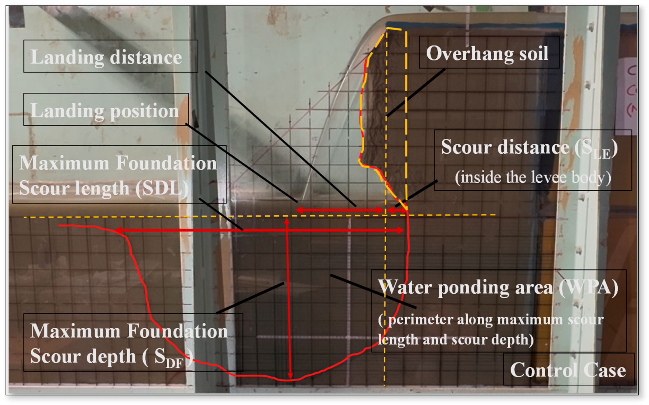
The measuring or observation parameters are listed below and in Figure 4. On the glass surface of the experimental flume, a scale was drawn at 5 cm intervals, and nappe flow erosion was recorded with video cameras on the side and top. During the experiment run, changes in flow conditions and the levee shape were confirmed, as was the landing distance of the falling flow. The scouring distance inside the levee body and maximum scouring depths and lengths in the levee foundation were measured at 5-minute intervals. Measurements focused on the following key parameters to evaluate the effectiveness of each configuration:

Figure 4.
Parameters for observations and measurements to evaluate the effectiveness of each configuration.
Landing distance: the water landing distance represents the horizontal distance from the shoulder of the back slope to the position where the flow vein lands on the foundation.
Overflow time is the time from when water begins to overflow above the crest until the entire levee foundation is eroded and the levee body collapses, or the foundation of the levee is eroded to full length.
Maximum Foundation Scour depth (SDF): The vertical distance measured from the foundation surface to the deepest point of erosion at the base of the flume. This depth indicates the extent of erosion and highlights the potential risk to foundation stability, with positive values representing downward erosion.
Maximum Foundation Scour Length (SDL): Length of erosion observed at the base of the flume, indicating vulnerability to foundation instability.
Scouring Inside the Levee Body (SLE): Depth of erosion observed within the levee body itself, indicating internal stability and the potential for structural damage. A negative value indicates that erosion has occurred inside the levee body below the crest called scouring inside the levee body (SLE), as shown in Table 1.
Overhang Soil Area (OSA): Overhang soil forms when erosion removes the supporting material beneath the soil layer, leaving an unsupported section that projects outward. This condition is highly vulnerable to collapse and is a significant indicator of potential levee failure.
Water Ponding Area (WPA): Water ponding refers to the accumulation of water in a depression or scour hole formed due to erosion from nappe flow striking. Larger ponding areas indicate more extensive erosion, which can significantly compromise the stability and integrity of the levee, indicating potential vulnerabilities and increasing the risk of structural failure due to concentrated hydraulic stress.
The results were recorded at the 30-minute mark for all configurations, regardless of whether the levee had collapsed by that time.
3. Results
The experiment results are divided into two categories: Series I experiments with a levee crest of 40 cm from case 2 to case 7, and Series II experiments focus on the extended levee crest to 60 cm (case 8 and case 9), as shown in Table 1. Findings of all cases and the effects of each drainage layer on the levee erosion and destruction mechanisms are summarized in Table 2 and discussed below. The focus was on time, water, scouring distance inside the levee body, water ponding area (WPA), overhang soil area (OSA), maximum erosion depth (SDF), and length within the foundation (SLE).
Table 2.
Summary of all experimental cases of nappe flow erosion tests.
3.1. Control Case (Case 1 CCNHD)
3.1.1. Erosion Profile at 120 Seconds
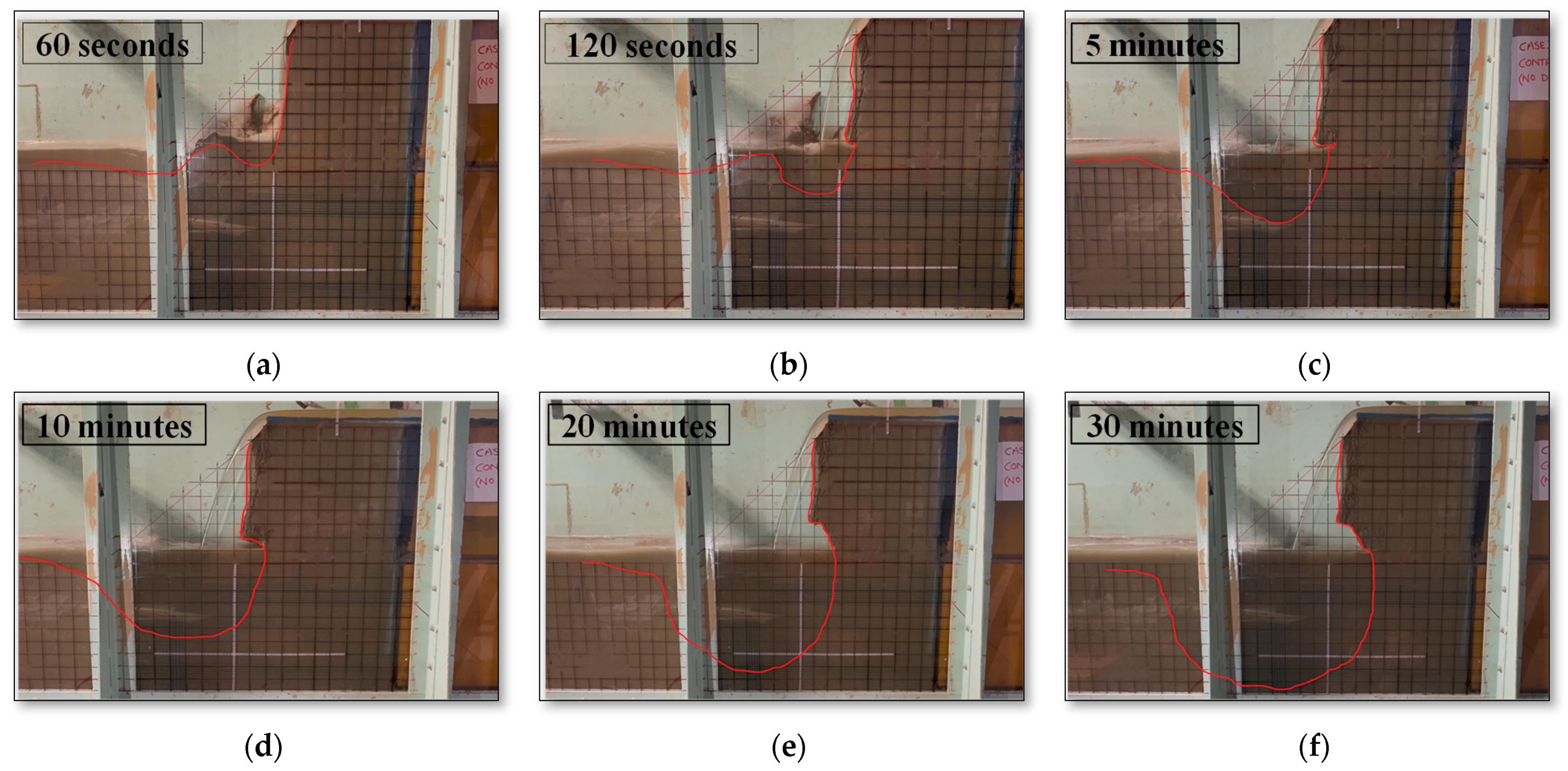
At 120 seconds, a significant foundation scour was evident, with erosion progressing rapidly towards the levee body. The scour depth in the foundation (SDF) reached 20 cm, while the levee body scour (SLE) had not started yet, as shown in Figure 5a,b.

Figure 5.
Topography evolution images during the experiment at different time intervals for case I CCNHD (red lines showing the propagation of scour profile).
Initial Stages: Downstream slope erosion started rapidly in the first 30 seconds, characterized by arc surface head cuts and slope smooth sliding failures, like Stage I and II erosion observed during overflow cases in Ali and Tanaka [33].
Nappe Flow Formation: By 60 seconds, the downstream slope was completely eroded, and the nappe flow was fully formed as shown in Figure 5a,b. After nappe flow formation, erosion progressed to the levee foundation, and the water ponding area formed due to the deep scouring by nappe flow.
Erosion Progression: Erosion progression continued after the initial rapid erosion, though at a slower pace. At 2 minutes, the foundation scour depth (SDF) reached 7 cm. By 5 minutes, it had increased to approximately 20 cm, as shown in Figure 5c. At 10 minutes, the SDF reached 27 cm, as illustrated in Figure 5d. By 20 minutes, SDF had grown to about 41 cm, and erosion inside the levee body had begun, accompanied by some collapse of overhang soil, indicating a threat to levee stability. The levee body scour (SLE) was approximately 2 cm at this point, as depicted in Figure 5e. Finally, at 30 minutes, the foundation scour depth reached its maximum of 47 cm, with erosion inside the levee body measuring about 5 cm, as shown in Figure 5f.
3.1.2. Final Erosion Profile
After 30 minutes, a significant foundation scour (SDF = 47 cm) and levee body scour (SLE = 5 cm) were observed, as shown in Figure 5f. The levee foundation was fully eroded, representing the worst-case scenario for levee body stability. As the foundation was fully scoured and progressed towards the levee body, 30 minutes was the maximum runtime for the test, and all other cases were compared against this 30-minute run time.
3.2. Full-Length Horizontal Drainage Layers (Case 2: HD15L50 and Case 3: HD25L50)
3.2.1. Erosion Profile at 120 Seconds
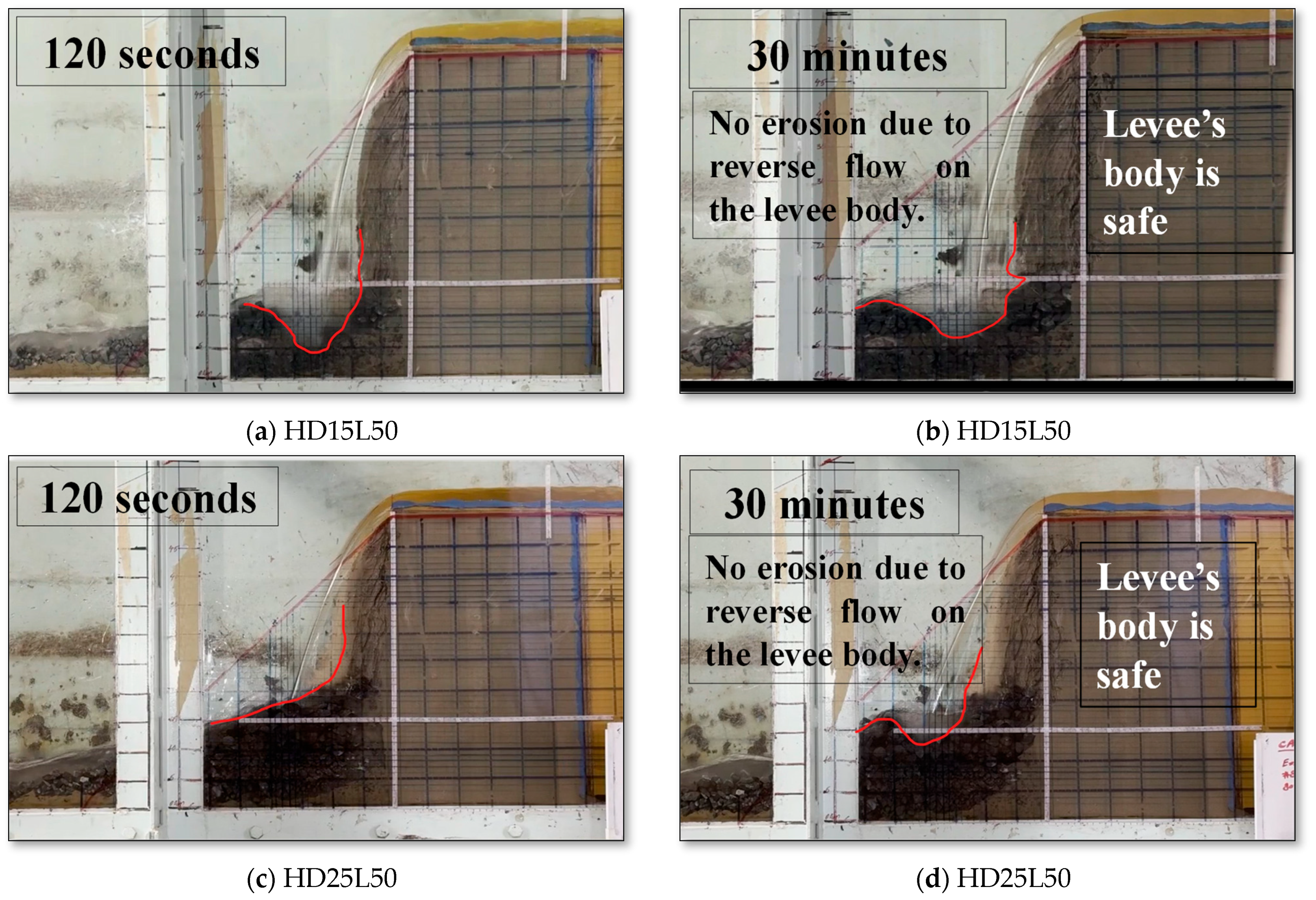
Both configurations showed minimal erosion till 120 seconds. No notable scour was observed in either the foundation or the levee body, indicating the effectiveness of full-length horizontal drainage layers in mitigating initial erosion, as shown in Figure 6a,c.

Figure 6.
Topography evolution images during the experiment at 120-second and 30-minute time intervals (a,b) for case HD15L50 and (c,d) for case HD25L50 (red lines showing the propagation of scour profile).
Initial Stages: Downstream slope erosion started similarly to the control case, with Stage I and II erosion initiating the nappe flow formation within 60 s, as illustrated in Figure 6a,c. Nappe flow initiation did not lead to further erosion inside the levee foundation. However, as the horizontal drainage material became exposed and the nappe flow struck it, only small erosion occurred within the drainage layer.
Energy Dissipation: The horizontal drainage layer effectively dissipated the hydraulic energy, providing protection to the levee body and preventing the formation of a main reverse flow. This prevented significant further slope sliding failures or foundation scouring typically associated with nappe flow initiation. HD25L50 showed less scouring inside the drainage layer, showing more dissipation of energy due to the higher thickness of the drainage layer.
3.2.2. Final Erosion Profile
No scour was observed inside the levee body or levee foundation throughout the 30-minute duration in both configurations, as depicted in Figure 6b,d. The full-length horizontal drainage layers effectively prevented both foundation and levee body scour, demonstrating their superior protection. There was no formation of overhang soil, and WPA was minimal, indicating effective erosion control and stability of the levee body.
Even after 30 minutes of the experiment run time, the levee body and foundation remained intact, highlighting the effectiveness of these drainage layers in mitigating erosion.
3.3. Partial-Length Horizontal Drainage Layers (Case 4: HD15L40 and Case 5: HD25L40)
3.3.1. Erosion Profile at 120 Seconds
Initial Stages: Downstream slope erosion began within the first 30 seconds and nappe flow formed by 60 seconds. Nappe flow started to cause levee foundation erosion, but the damage was less severe compared to the control case.
Partial-Length Effect: Due to the reduced length of the drainage layers (40 cm, covering about 80% of the downstream slope length), the impinging distance was at the edge of the layer. While the drainage layer provided some cushion for energy dissipation, its shorter length allowed for noticeable reverse flow towards the levee body.
Scouring: Partial-length configurations exhibited some scouring inside the levee body for 120 seconds. The scour depth inside the levee body (SLE) for both configurations was around 3 cm, while the foundation remained stable with minimal scour observed. The nappe flow caused downstream slope erosion, but the damage was less severe compared to the control case.
3.3.2. Final Erosion Profile
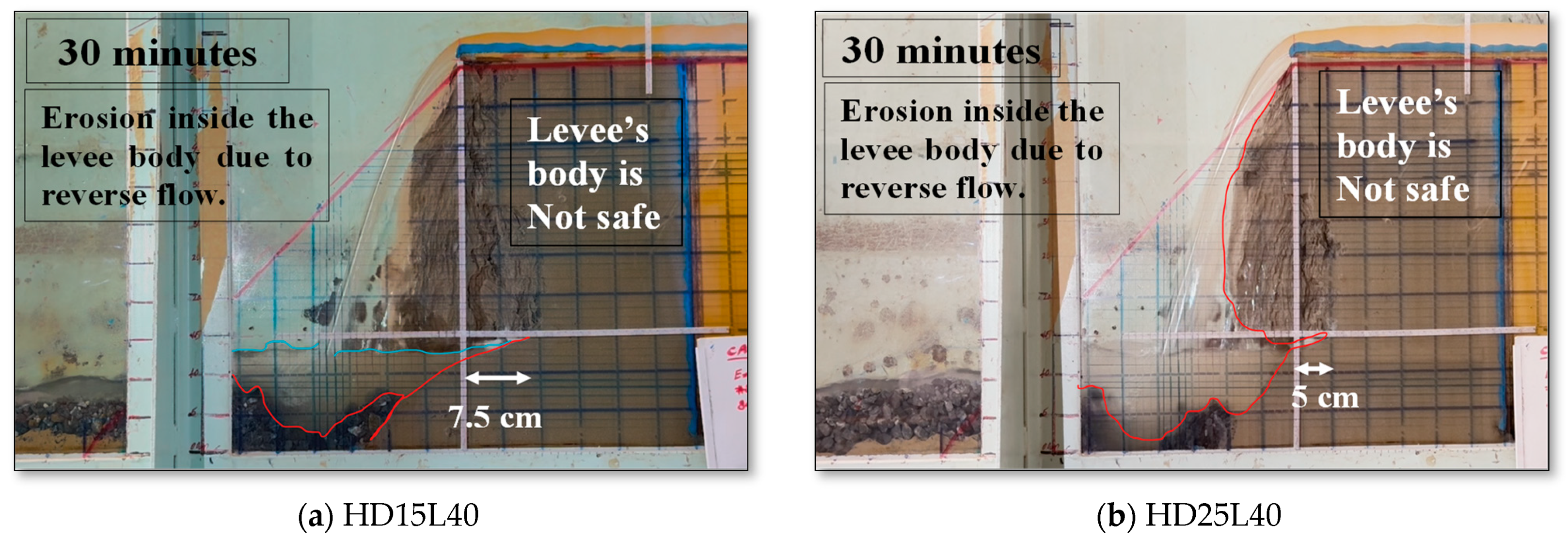
Scour Development: After 30 minutes, significant scouring was observed inside the levee body due to the reduced length of the drainage layers. In case 4 HD15L40, with a 15 cm thick drainage layer, the scour inside the levee body (SLE) reached about 7.5 cm, as shown in Figure 7a. In case 5 HD25L40, with a 25 cm thick drainage layer, the scour inside the levee body (SLE) was about 5 cm, as illustrated in Figure 7b.

Figure 7.
Topography evolution images during the experiment at a 30-minute time interval for (a) case HD15L40 and (b) case HD25L40 (red lines showing the propagation of scour profile).
Reverse Flow Impact: The reduction in layer length allowed for evident reverse flow towards the levee body, contributing to the internal scour. This internal erosion is particularly dangerous as it leaves large overhangs of soil, posing a significant threat to levee stability.
Foundation Scour: While the foundation scour remained minimal, the internal levee stability was compromised due to the reduced length of the drainage layers, highlighting the potential for failure.
Overhang soil and water ponding: The erosion within the levee body left a substantial portion of overhang soil, indicating vulnerability to collapse as erosion further extends within the levee body. Water ponding was observed, showing weak points in the foundation that could lead to further erosion and instability.
The findings underscore the importance of adequate drainage layer length in preventing reverse flow and internal erosion, which are critical for maintaining levee integrity.
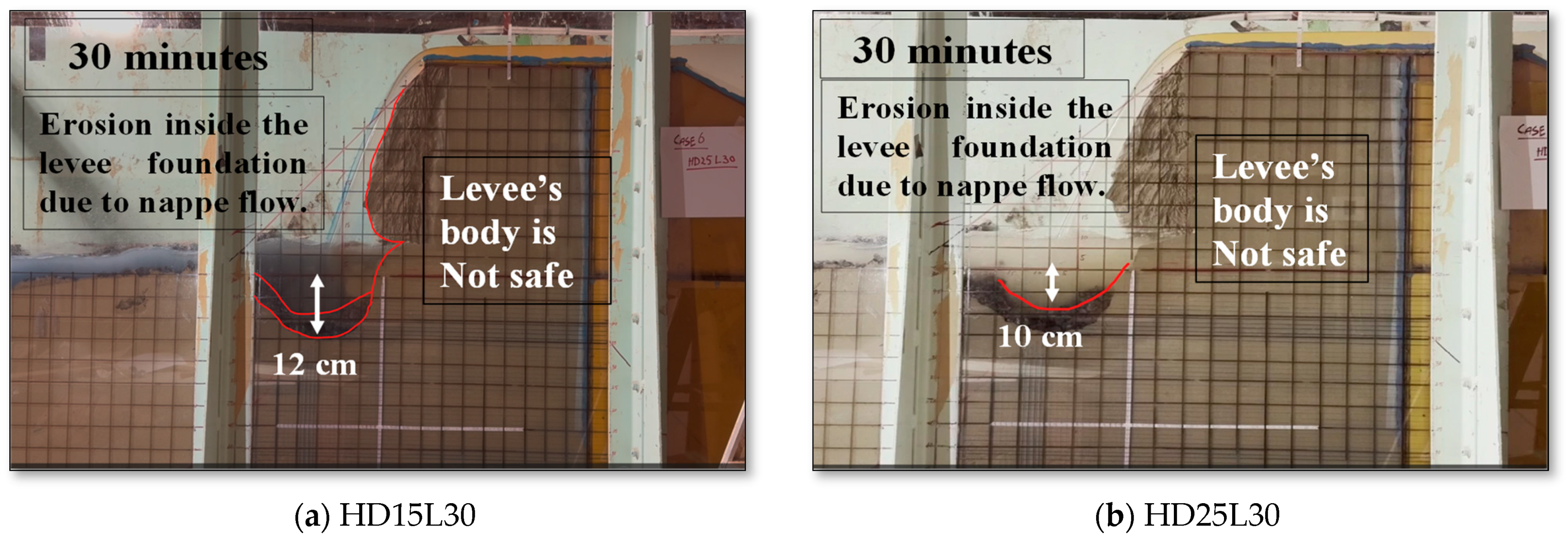
3.4. Reduced-Length Horizontal Drainage Layers (Case 6: HD15L30 and Case 7: HD25L30)
3.4.1. Erosion Profile at 120 Seconds
Initial Stages: Downstream slope erosion occurred similarly to the full-length and partial-length cases of Stage I and II overflow erosion, as in Ali and Tanaka [33] overflow cases.
Nappe Flow Formation: By 60 seconds, nappe flow started. With the drainage layer length reduced to 60% of the downstream slope length, the impinging distance was slightly inside the levee body downstream slope and drainage layer.
Material Washout: The nappe flow pushed the drainage material, and most of it was washed away. Erosion began in the levee foundation, and some drainage material moved into the WPA, or foundation erosion hole. However, the reduced quantity of drainage material led to less energy dissipation, resulting in significant foundation scour.
Scour Depth: At 120 seconds, nappe flow was fully developed, and foundation scour was just going to start, but there was no noticeable levee body scour at this stage. This indicated that while foundation erosion was evident, the levee body initially remained protected.
3.4.2. Final Erosion Profile
Scour Progression: After 30 minutes, substantial foundation scour was observed. In case HD15L30, the foundation scour depth (SDF) reached 12 cm, as shown in Figure 8a. In case HD25L30, the foundation scour depth (SDF) reached 10 cm, as illustrated in Figure 8b.

Figure 8.
Topography evolution images during the experiment at 30-minute time interval for (a) case HD15L30 and (b) case HD25L30 (red lines showing the propagation of scour profile).
Foundation Erosion Impact: Despite the substantial foundation scours, no levee body scour was noted. The scouring in the foundation posed a significant risk to levee stability. If the scour depth expands further, it may lead to the collapse of the levee body.
Overhang soil and water ponding: Overhang soil formation was small, but WPA formation was significant, indicating a weakening of the foundation and extending towards the levee body, posing a risk of future instability.
The findings highlight that while reduced-length horizontal drainage layers initially protect the levee body, they are less effective in preventing significant foundation erosion, which could eventually compromise the stability of the levee.
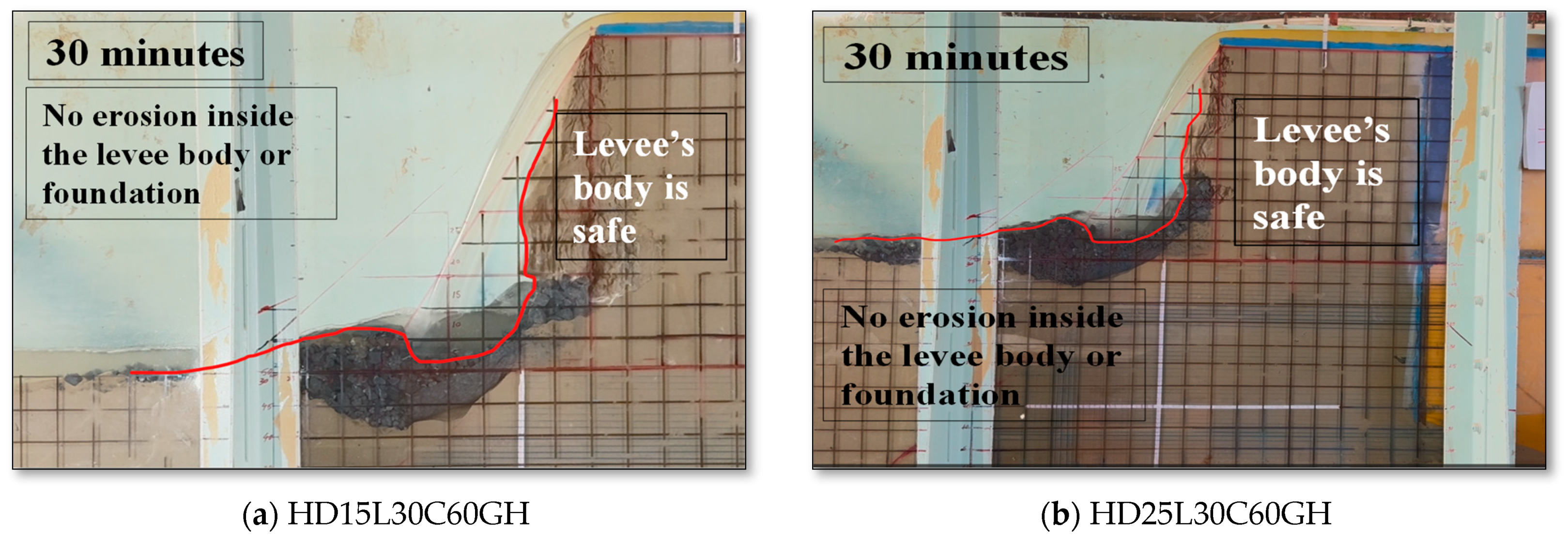
3.5. Extended Crest Length with Gauzed Sheets (HD15L30C60GH and HD25L30C60GH)
3.5.1. Erosion Profile at 120 Seconds
When the levee crest was extended to 60 cm, creating a steeper downstream slope that replicated the conditions of the full-length drainage case, no scour was observed in either the foundation or levee body. Although downstream slope erosion began rapidly within the first 30 seconds, like in previous cases. However, when the drainage layer was exposed, it provided a protective cushion. This led to significant energy dissipation and effectively prevented further erosion.
3.5.2. Final Erosion Profile
Final profiles indicated no scour in either the foundation or levee body. The addition of gauzed sheets, which replicated the drainage layer in the actual scenario, further enhanced the drainage system’s efficiency, maintaining stability and preventing erosion, as shown in Figure 9a,b. There was minimal erosion within the drainage layer itself, demonstrating its effectiveness in mitigating the impact of overtopping and nappe flow, as evident from Figure 9a,b. No overhang soil was observed, and WPA was minimal, highlighting the effectiveness of this configuration in protecting the levee body.

Figure 9.
Topography evolution images during the experiment at 30-minute time intervals for (a) case HD15L30C60GH and (b) case HD25L30C60GH (red lines showing the propagation of scour profile).
Nappe flow continued for the entire 30-minute duration, but equilibrium was achieved after the initial drainage layer erosion, allowing it to function similarly to the full-length drainage layer.
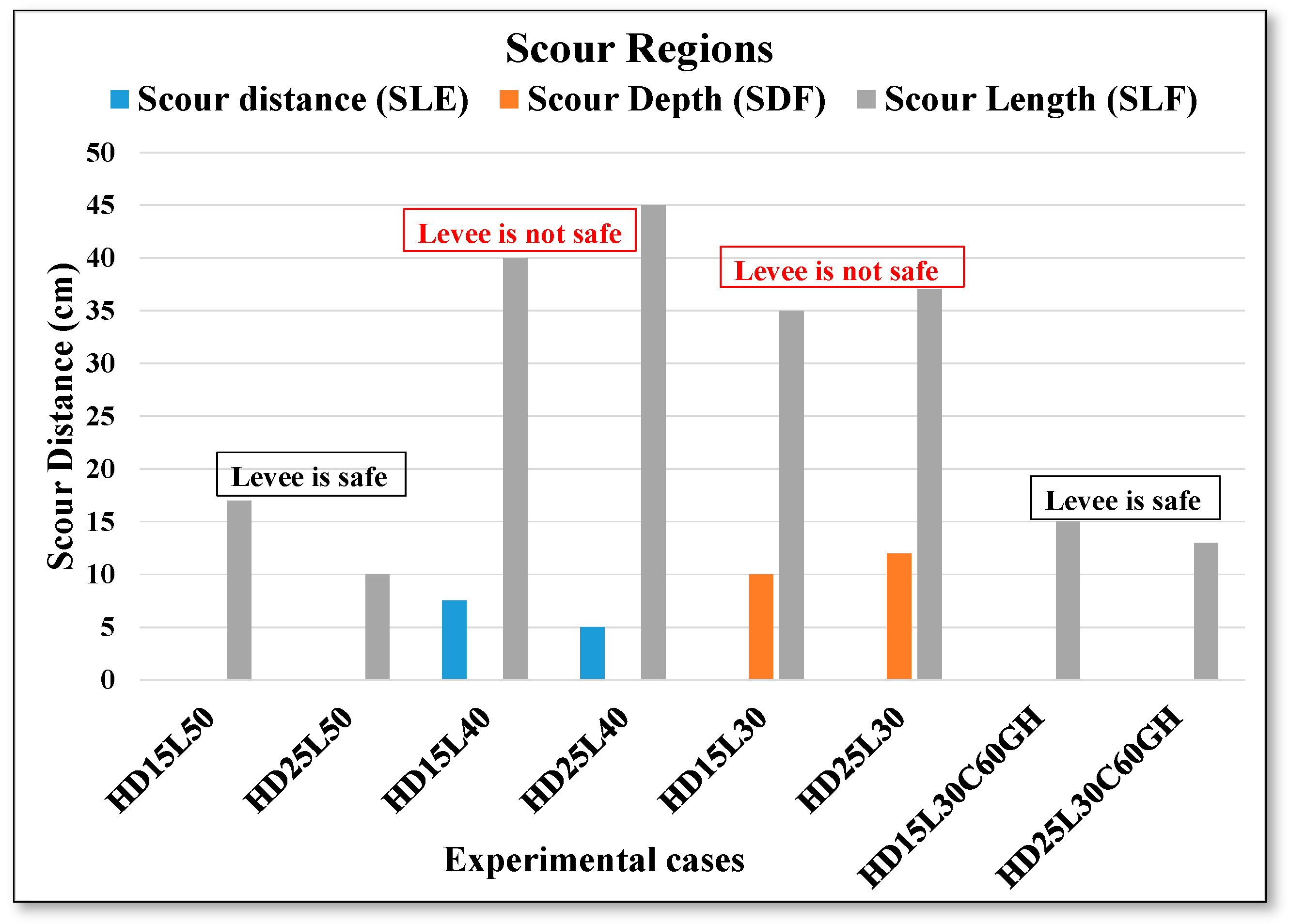
3.6. Comprehensive Erosion Analysis and Vulnerability Indicators
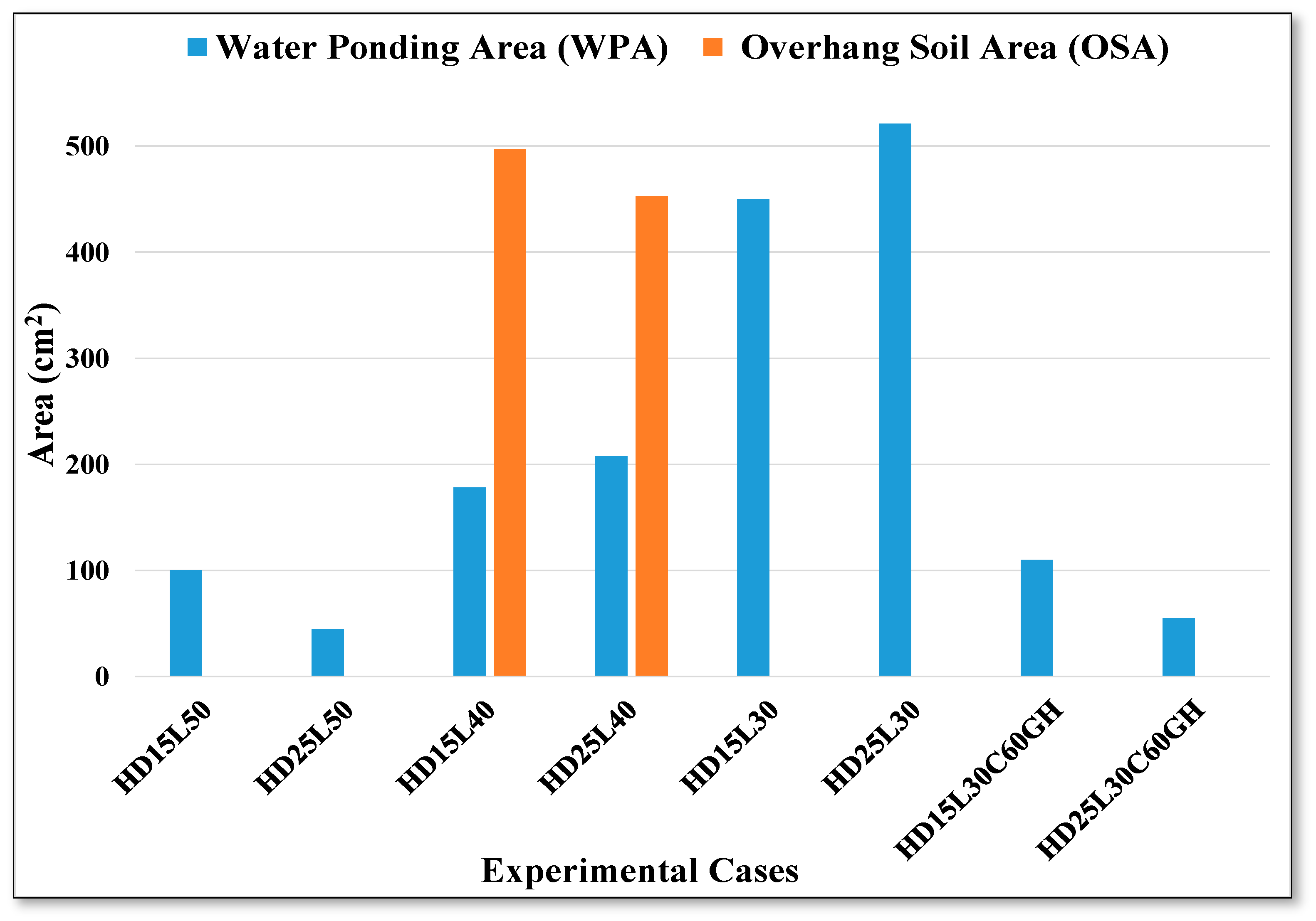
This comprehensive results section combines the initial erosion profiles at 120 s with the final erosion profiles for all cases. A summary of all cases has been presented in Table 2, offering a concise overview of the experimental outcomes. Figure 10 illustrates the scour characteristics, including depths and lengths for all cases, while Figure 11 highlights the overhang soil and WPA, which are indicators of vulnerability. These provide a clear comparison of the effectiveness of various configurations in mitigating erosion by examining different observation and measurement parameters. The presence of overhang soil indicates areas where the levee structure is particularly vulnerable to failure. Overhang soil was observed in Partial-Length Horizontal Drainage Layers (case 4 HD15L40 and case 5 HD25L40), as shown in Figure 11 with orange color bars. Similarly, water ponding areas are indicative of significant scour holes; larger ponding areas suggest more extensive erosion, which further compromises the levee’s integrity. It was significant in the case of Reduced-Length Horizontal Drainage Layers (case 6 HD15L30 and case 7 HD25L30), as shown in Figure 11 blue color bars. These indicators are crucial in assessing the overall stability and effectiveness of different levee configurations in controlling erosion and mitigating the impacts of overtopping and nappe flow. Through this detailed analysis, the relative performance of each configuration is assessed, shedding light on their respective strengths and weaknesses in erosion control.

Figure 10.
Scour regions (scour length, scour depth, and scour distance inside the levee body) for series I and II experiments.

Figure 11.
Areas of water ponding and overhang soil for series I and II experiments.
4. Discussion
4.1. Effectiveness of Horizontal Drainage Layers
The study demonstrates the effectiveness of horizontal drainage layers in mitigating nappe flow-induced reverse flow and levee body erosion. These drainage layers significantly reduce seepage pressures, thereby enhancing levee stability and resilience. The implications of these findings align with existing literature and suggest future research directions.
Recommendations for Newly Constructed Levees (Full-Length Horizontal Drainage Layers)
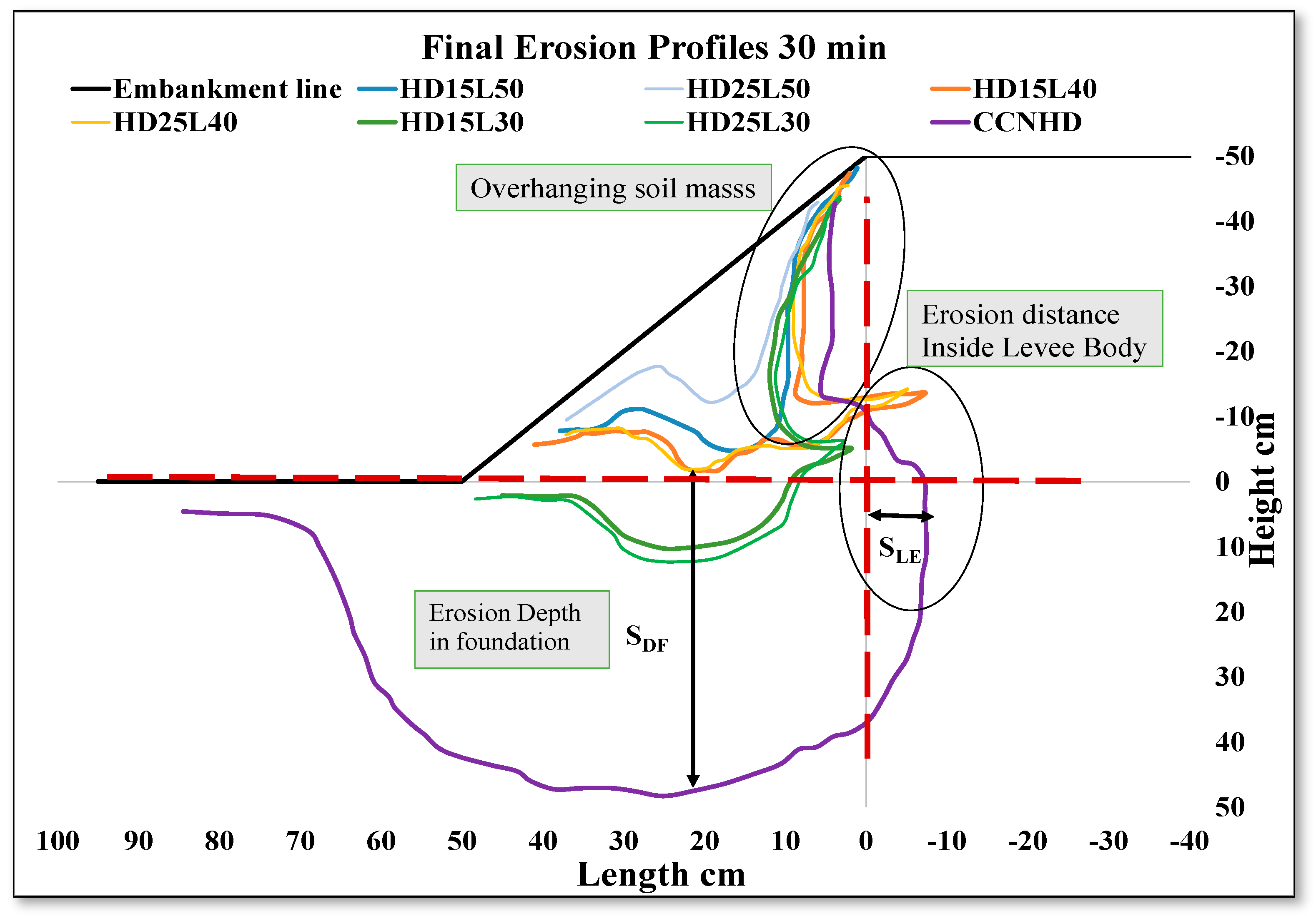
Series I experiments confirmed the exceptional performance of full-length horizontal drainage layers (HD15L50 and HD25L50) in mitigating nappe flow along with fulfilling its intended purpose of seepage and recommended for the newly constructed levees. These layers effectively dissipate hydraulic energy, preventing both foundation and levee body scour, as shown in Figure 12 (blue and light blue erosion profiles). The absence of overhang soil and minimal water ponding (Figure 11) further highlights their efficacy. Partial-length and reduced-length drainage layers provided limited protection but failed to prevent significant erosion, leading to potential foundation instability, as depicted in Figure 12 (orange, light orange, and green, and light green erosion profiles, respectively). This emphasizes the importance of designing levee drainage systems with sufficient length for optimal protection against nappe flow erosion after overtopping a levee. Full-length horizontal drainage layers are essential for newly constructed levees to ensure comprehensive protection against nappe flow erosion.

Figure 12.
Final erosion profiles identified from video images at 30 minutes for series I experiments.
4.2. Retrofitting Existing Levees (Extended Crest Length)
4.2.1. Innovative Solution
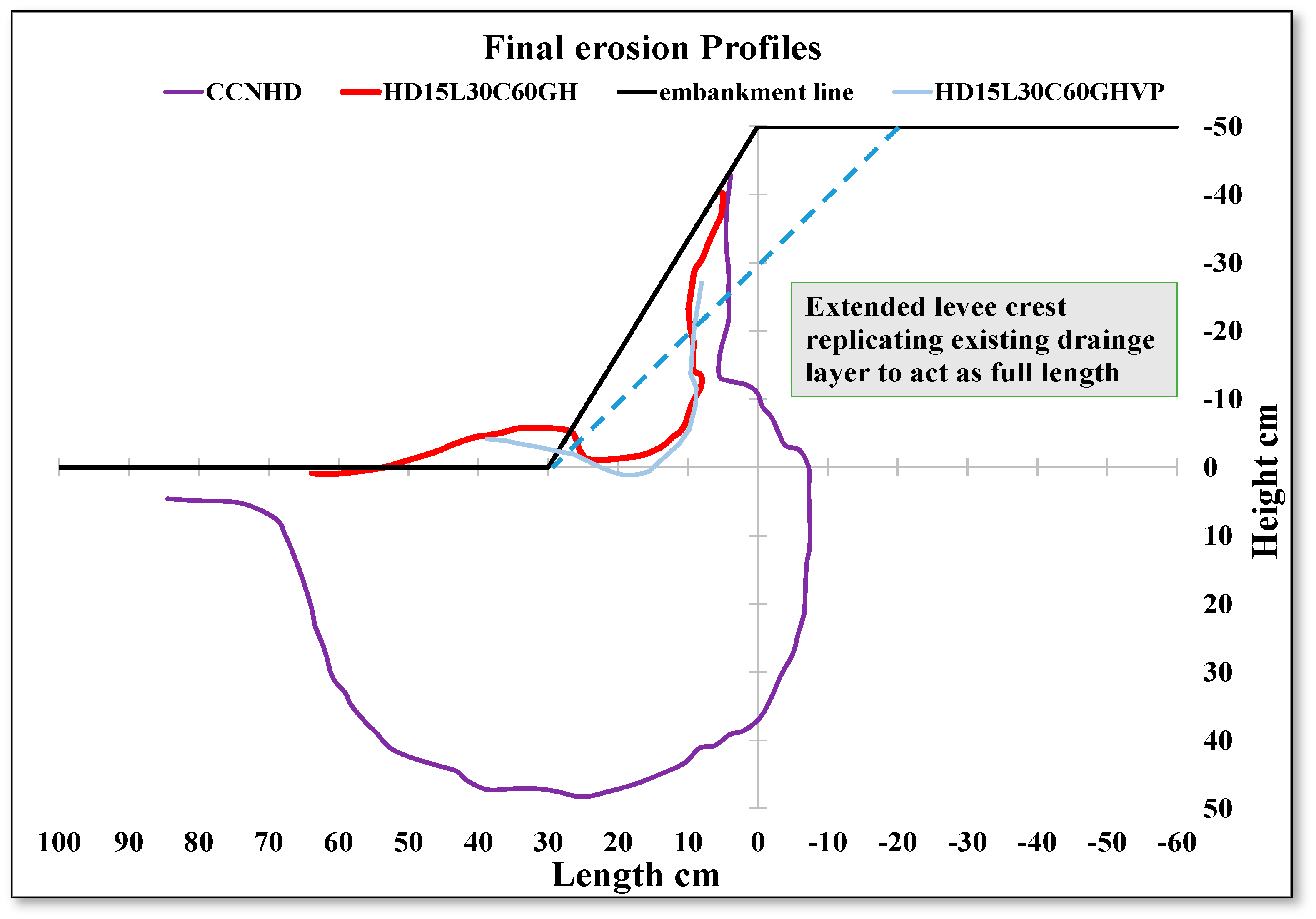
To address the limitations of existing levees, this study proposes extending the levee crest length to the edge of the existing drainage layer. This modification allowed shorter drainage layers to effectively replicate the performance of full-length layers in mitigating nappe flow erosion. Experiments showed that extending the crest from 40 cm to 60 cm enabled a 30 cm drainage layer to prevent erosion inside the levee body and foundation, as evident from scour profiles in Figure 13. This approach offers a practical retrofit solution for existing levees, ensuring their continued stability and safety against hydraulic stresses.

Figure 13.
Final erosion profiles identified from video images at 30 minutes for series II experiments (dashed line shoes the extended levee crest).
4.2.2. Practical Significance and Recommendations
The innovative approach of extending the crest length and incorporating gauzed sheets presents a cost-effective and feasible solution for enhancing the resilience of existing levee systems. This method effectively mitigates the erosive impacts of nappe flow, addressing the practical constraints of retrofitting full-length drainage layers. Implementing the strategy of extending the crest length levee management and maintenance practices can significantly contribute to the future sustainability and safety of levee infrastructures, ensuring their continued protection against hydraulic challenges and environmental stresses.
4.3. Comparison with Previous Research
In the present study, the primary focus was on understanding how horizontal drainage layers can mitigate erosion caused by nappe flow during overtopping events. Unlike previous research that predominantly explored the role of drainage layers in seepage control, this study specifically investigated their effectiveness in managing erosion induced by overtopping flow. Ali and Tanaka [33] investigated levee erosion, but their experiments addressed both overflow and infiltration, considering varied hydraulic conductivities of the levee and foundation materials. Before the initiation of nappe flow, the current study observed the downstream scour was similar. This similarity highlights the consistency in erosion patterns under overtopping conditions, especially when considering the exposure of drainage layers. The findings from the current study demonstrate that full-length horizontal drainage layers were particularly effective in preventing erosion, with zero scouring observed within the levee body and foundation. This contrasts sharply with the control case, where significant erosion and scouring were evident. This also aligns with the findings of Wahl [12], who observed significant erosion reduction using riprap under overtopping conditions but used riprap on the slope of the levee, which only focuses on overtopping erosion. Chanson [11] emphasized the necessity of drainage systems to manage overtopping flow, but this study goes further by showing that extending the drainage layer across the full length of the levee body completely prevented internal erosion acting as a dual-function drainage layer. Previous studies, such as those by Abbas and Tanaka [7], explored methods to reduce the impact of nappe flow on the downstream side of a levee, such as using geogrids and water cushions. While effective, these approaches did not address the erosion within the levee body itself. This study fills the gap by demonstrating that horizontal drainage layers can eliminate internal erosion under similar conditions. While the current study did not focus on seepage erosion, it is worth noting that horizontal drainage layers have been widely used in previous studies for seepage control. For instance, Takahashi [40] and Zhang et al. [41] highlighted the role of drainage layers in reducing seepage pressures and enhancing stability under different hydraulic conditions. However, current research uniquely contributes to the field by applying these drainage layers to manage nappe flow, showing their effectiveness in overtopping scenarios without addressing seepage. For retrofitting existing levees, the study found that configurations with extended crest lengths and gauzed sheets effectively replicated the protective effects of full-length drainage layers. This finding offers a practical solution for upgrading existing levees, providing performance comparable to full-length layers. This contribution extends the research of Abbas and Tanaka [7], who focused on scouring reduction but did not evaluate retrofitting methods.
5. Conclusions
This study emphasizes the effectiveness of full-length horizontal drainage layers for newly constructed levees and explores practical retrofitting solutions for existing levees through extended crest lengths and gauzed sheets. The specific conclusions of the study are below.
- Full-length horizontal drainage layers (HD15L50 and HD25L50, where the thicknesses are 15 and 25 cm, respectively, with a horizontal drainage layer length of 50 cm and a crest length of 40 cm) provided superior protection against both foundation and levee body erosion due to nappe flow. Their ability to effectively dissipate hydraulic energy makes them ideal for newly constructed levees.
- While partial-length drainage layers (HD15L40 and HD25L40) offered some level of protection, these layers were less effective compared to full-length configurations. They exhibited reduced energy dissipation and higher susceptibility to reverse flow, leading to internal levee erosion and overhang soil formation.
- Reduced-length drainage layers (HD15L30 and HD25L30) were less effective in preventing foundation scouring, with substantial scour hole formation and water ponding, indicating a weakened foundation and potential risk to levee stability.
- Configurations with extended crest length and gauzed sheets (HD15L30C60GH and HD25L30C60GH) effectively replicated the protective effects of full-length drainage layers. These configurations showed minimal erosion, no overhang soil formation, and effective energy dissipation, making them a viable retrofit solution for existing levees.
For new levee construction, full-length drainage layers are recommended for optimal performance. For retrofitting existing levees, extending the levee crest and using gauzed sheets can enhance resilience against nappe flow-induced erosion.
Future studies should investigate the long-term performance of these countermeasures under varying hydraulic conditions and potential environmental impacts. Numerical simulations and field studies could further refine understanding of nappe flow dynamics and erosion processes, contributing to more resilient and sustainable flood protection infrastructure.
Author Contributions
Conceptualization, L.A., K.S. and N.T.; methodology, L.A.; model preparation, L.A. and K.S.; investigation, L.A. and K.S.; data processing and analysis, L.A.; writing—original draft, L.A.; visualization, L.A.; resources, N.T.; writing—review and editing, N.T.; supervision, N.T.; project administration, N.T.; funding acquisition, N.T. All authors have read and agreed to the published version of the manuscript.
Funding
This research received no external funding.
Data Availability Statement
The original contributions presented in the study are included in the article, further inquiries can be directed to the corresponding author.
Acknowledgments
The authors appreciate the support from the Japanese Ministry of Education, Culture, Sports, Science, and Technology (Monbukagakusho–MEXT Scholarship). The authors also acknowledge the anonymous reviewers for their valuable comments to improve this manuscript.
Conflicts of Interest
The authors declare no conflicts of interest.
References
- Jeon, J.; Tomita, T. Investigating the Effects of Super Typhoon HAGIBIS in the Northwest Pacific Ocean Using Multiple Observational Data. Remote Sens. 2022, 14, 5667. [Google Scholar] [CrossRef]
- Moriguchi, S.; Matsugi, H.; Ochiai, T.; Yoshikawa, S.; Inagaki, H.; Ueno, S.; Suzuki, M.; Tobita, Y.; Chida, T.; Takahashi, K.; et al. Survey report on damage caused by 2019 Typhoon Hagibis in Marumori town, Miyagi prefecture, Japan. Soils Found. 2021, 61, 586–599. [Google Scholar] [CrossRef]
- Irasawa, M.; Koi, T.; Tsou, C.Y.; Kato, N.; Matsuo, S.; Arai, M.; Kon, T. October 2019 sediment disaster in the Tohoku region owing to typhoon no. 19 (Typhoon Hagibis). Int. J. Eros. Control. Eng. 2020, 13, 48–55. [Google Scholar] [CrossRef]
- Van, M.; Rosenbrand, E.; Tourment, R.; Smith, P.; Zwanenburg, C. Failure Paths for Levees. International Society of Soil Mechanics and Geotechnical Engineering (ISSMGE)—Technical Committee TC201 ‘Geotechnical Aspects of Dikes and Levees’. February 2022. Available online: https://issmge.org/files/reports/TC201-Failure-paths-for-levees.pdf (accessed on 20 June 2024).
- Chanson, H. Hydraulics of nappe flow regime above stepped chutes and spillways. Aust. Civ./Struct. Eng. Trans. 1994, 1, 69–76. [Google Scholar]
- Silva-Araya, W.F.; Alva-Solari, L.; Chaudhry, M.H. Experimental study of levee breach. In Proceedings of the 21st Century Watershed Technology: Improving Water Quality and Environment Conference, Guacimo, Costa Rica, 21–24 February 2010; pp. 423–429. [Google Scholar]
- Abbas, F.M.; Tanaka, N. Utilization of geogrid and water cushion to reduce the impact of nappe flow and scouring on the downstream side of a levee. Fluids 2022, 7, 299. [Google Scholar] [CrossRef]
- Dissanayaka, K.D.C.R.; Tanaka, N.; Hasan, M.K. Effect of orientation and vegetation over the embankment crest for energy reduction at downstream. Geosciences 2022, 12, 354. [Google Scholar] [CrossRef]
- Esteban, M.; Glasbergen, T.; Takabatake, T.; Hofland, B.; Nishizaki, S.; Nishida, Y.; Stolle, J.; Nistor, I.; Bricker, J.; Takagi, H.; et al. Overtopping of Coastal Structures by Tsunami Waves. Geosciences 2017, 7, 121. [Google Scholar] [CrossRef]
- Pan, Y.; Li, L.; Amini, F.; Kuang, C. Influence of three levee-strengthening systems on overtopping hydraulic parameters and hydraulic equivalency analysis between steady and intermittent overtopping. J. Waterw. Port Coast. Ocean. Eng. 2013, 139, 256–266. [Google Scholar] [CrossRef]
- Chanson, H. Embankment overtopping protection systems. Acta Geotech. 2015, 10, 305–318. [Google Scholar] [CrossRef]
- Wahl, T.L. Embankment overtopping protection by riprap considering interstitial flow. In Proceedings of the 2nd International Seminar on Dam Protection against Overtopping, Protections 2016, Ft. Collins, CO, USA, 7–9 September 2016; ISBN 978-1-1889143-27-9. [Google Scholar]
- Al-Riffai, M. Experimental Study of Breach Mechanics in Overtopped Noncohesive Earthen Embankments. Doctoral Dissertation, University of Ottawa, Ottawa, ON, Canada, 2014. [Google Scholar]
- Powledge, G.R.; Dodge, R.A. Overtopping of small dams—An alternative for dam safety. In Hydraulics and Hydrology in the Small Computer Age; ASCE: Reston, VA, USA, 1985; pp. 1071–1076. [Google Scholar]
- Powledge, G.R.; Ralston, D.C.; Miller, P.; Chen, Y.H.; Clopper, P.E.; Temple, D.M. Mechanics of overflow erosion on embankments. II: Hydraulic and design considerations. J. Hydraul. Eng. 1989, 115, 1056–1075. [Google Scholar] [CrossRef]
- Powledge, G.R.; Ralston, D.C.; Miller, P.; Chen, Y.H.; Clopper, P.E.; Temple, D.M. Mechanics of overflow erosion on embankments. I: Research activities. J. Hydraul. Eng. 1989, 115, 1040–1055. [Google Scholar] [CrossRef]
- Briaud, J.L.; Chen, H.C.; Govindasamy, A.V.; Storesund, R. Levee erosion by overtopping in New Orleans during the Katrina Hurricane. J. Geotech. Geoenviron. Eng. 2008, 134, 618–632. [Google Scholar] [CrossRef]
- Xu, Y.; Zhang, L.M. Breaching parameters for earth and rockfill dams. J. Geotech. Geoenviron. Eng. 2009, 135, 1957–1970. [Google Scholar] [CrossRef]
- Zhu, Y. Breach Growth in Clay-Dikes. Doctoral Dissertation, Delft University of Technology, Delft, The Netherlands, 2006. [Google Scholar]
- Shinohara, A.; Nihei, Y.; Kurakami, Y.; Suzuki, K. Prevention of levee crest overtopping through reinforcement technology. In 21st Congress of International Association for Hydro-Environment Engineering and Research-Asia Pacific Division: Multi-Perspective Water for Sustainable Development, IAHR-APD 2018; Department of Civil and Environmental Engineering, Faculty of Engineering, Universitas Gadjah Mada: Yogyakarta, Indonesia, 2018; pp. 217–223. [Google Scholar]
- Yoshimori, Y.; Kurakami, Y.; Nihei, Y.; Morita, M. Understanding the scouring phenomenon at the bottom of the slope behind a dike and a basic study on the placement conditions of countermeasure works. J. Jpn. Soc. Civ. Eng. B2 (Coast. Eng.) 2015, 71, I_1117–I_1122. [Google Scholar]
- Johnson, E.B.; Testik, F.Y.; Ravichandran, N.; Schooler, J. Levee scour from overtopping storm waves and scour countermeasures. Ocean. Eng. 2013, 57, 72–82. [Google Scholar] [CrossRef]
- Ali, L.; Tanaka, N. Enhancing Levee Resilience Through Material Compatibility: A Comprehensive Study on Erosion Dynamics. Iran J. Sci. Technol. Trans. Civ. Eng. 2024, 1–15. [Google Scholar] [CrossRef]
- Fell, R.; Fry, J.J. The state of the art of assessing the likelihood of internal erosion of embankment dams, water retaining structures, and their foundations. In Internal Erosion of Dams and Their Foundations; CRS Press: Boca Raton, FL, USA, 2007; pp. 9–32. [Google Scholar]
- Crosta, G.; Prisco, C.D. On slope instability induced by seepage erosion. Can. Geotech. J. 1999, 36, 1056–1073. [Google Scholar] [CrossRef]
- Locci-Lopez, D.; Lorenzo, J.M. Seepage-induced pore pressure variations beneath an earthen levee measured with a novel seismic tool. Geosciences 2023, 13, 20. [Google Scholar] [CrossRef]
- Head, C. Department of the Army EM 1110-2-1913 US Army Corps of Engineers. 2000. Available online: https://policycommons.net/artifacts/1565930/department-of-the-army-em-1110-2-1913-u/2255713/ (accessed on 25 May 2024).
- Starosolszky, Ö. Flood control by levees. In Coping with Floods; Rossi, G., Harmancioğlu, N., Yevjevich, V., Eds.; NATO ASI Series; Springer: Dordrecht, The Netherland, 1994; Volume 257. [Google Scholar] [CrossRef]
- Sazzad, M.M.; Islam, M.M.A. comprehensive study of different types of seepage control measures for earth dams using FEM. J. Civ. Constr. Eng. 2019, 5, 24–37. [Google Scholar]
- USACE Publications. Available online: https://www.publications.usace.army.mil/Portals/76/Publications/EngineerDesignGuides/DG_1110-1-2.pdf (accessed on 10 June 2024).
- Defense Technical Information Center. General Design and Construction Considerations for Earth and Rockfill Dams. Available online: https://www.publications.usace.army.mil/portals/76/publications/engineermanuals/em_1110-2-2300.pdf (accessed on 25 June 2024).
- Wood, D.M. Geotechnical Modeling; CRC Press: London UK; New York, NY, USA, 2004; Volume 23. [Google Scholar]
- Ali, L.; Tanaka, N. Experimental investigation of levee erosion during overflow and infiltration with varied hydraulic conductivities of levee and foundation properties in saturated conditions. GeoHazards 2023, 4, 286–301. [Google Scholar] [CrossRef]
- Refaiy, A.R.; Nahla, M.A.; Neveen, Y.S.; El-Molla, A.D. Modeling the effect of downstream drain geometry on seepage through earth dams. Ain. Shams Eng. J. 2021, 12, 2511–2531. [Google Scholar] [CrossRef]
- Malekpour, A.; Farsadizadeh, D.; Hosseinzadeh Dalir, A.; Sadrekarimi, J. Effect of horizontal drain size on the stability of an embankment dam in steady and transient seepage conditions. Turk. J. Eng. Environ. Sci. 2012, 36, 139–152. [Google Scholar]
- Kouhpeyma, A.; Kilanehei, F.; Hassanlourad, M.; Ziaie-Moayed, R. Numerical and experimental modeling of seepage in homogeneous earth dam with combined drain. ISH J. Hydraul. Eng. 2022, 28, 292–302. [Google Scholar] [CrossRef]
- Morrill-Winter, J.; Fields, W.; Needham, J.T. Levee Breach Consequence Model Validated by Case Study in Joso, Japan; Association of State Dam Safety Officials, Inc.: Lexington, KY, USA, 2017. [Google Scholar]
- Ohtsuki, K.; Nihei, Y. Evaluation of fast flood diffusion through a drainage channel: A flood disaster case study of Japan’s Kinugawa River, September 10, 2015. J. Water Resour. Prot. 2017, 9, 1063–1081. [Google Scholar] [CrossRef]
- Shinohara, A.; Nihei, Y.; Kurakami, Y.; Suzuki, K. Study on the effectiveness of embankment top reinforcement technology for improving overtopping resistance as a crisis management hard measure. J. Jpn. Soc. Civ. Eng. B1 (Hydraul. Eng.) 2018, 74, I_1279–I_1284. [Google Scholar]
- Takahashi, A. Effects of horizontal drainage layer for seepage control on mitigation of liquefaction of levee body. J. Disaster Res. 2012, 7, 733–738. [Google Scholar] [CrossRef]
- Zhang, X.; Wang, H.; Gao, Z.; Xiang, K.; Zhai, Q.; Satyanaga, A.; Chua, Y.S. Evaluation of the Performance of the Horizontal Drain in Drainage of the Infiltrated Water from Slope Soil under Rainfall Conditions. Sustainability 2023, 15, 14163. [Google Scholar] [CrossRef]
Disclaimer/Publisher’s Note: The statements, opinions and data contained in all publications are solely those of the individual author(s) and contributor(s) and not of MDPI and/or the editor(s). MDPI and/or the editor(s) disclaim responsibility for any injury to people or property resulting from any ideas, methods, instructions or products referred to in the content. |
© 2024 by the authors. Licensee MDPI, Basel, Switzerland. This article is an open access article distributed under the terms and conditions of the Creative Commons Attribution (CC BY) license (https://creativecommons.org/licenses/by/4.0/).