


Innovative Photocatalytic Reactor for Sustainable Industrial Water Decontamination: Utilizing 3D-Printed Components and Silica-Titania Trilayer Coatings

 ,
,  ,
,  , and
, and 
Abstract
:1. Introduction
2. Materials and Methods
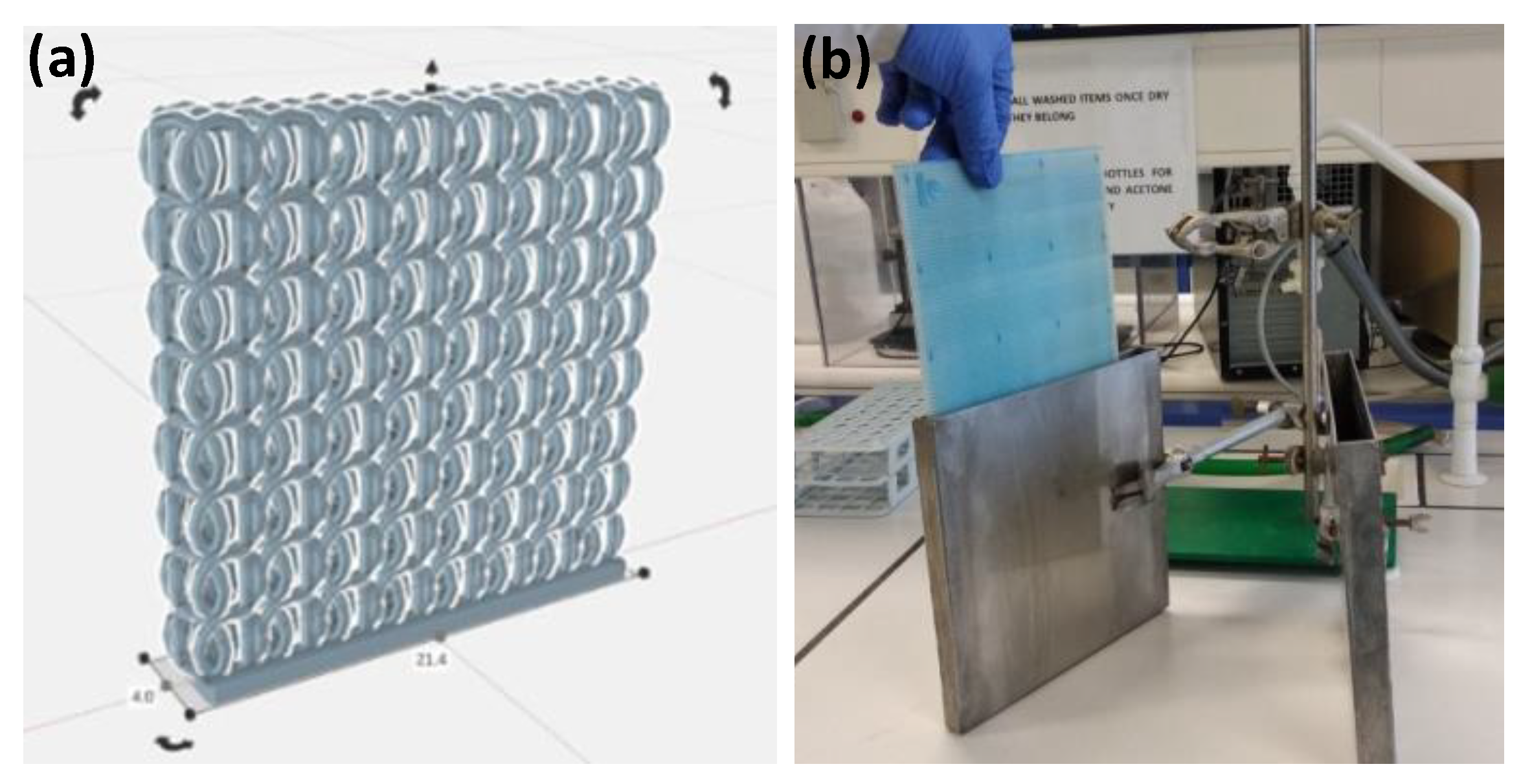
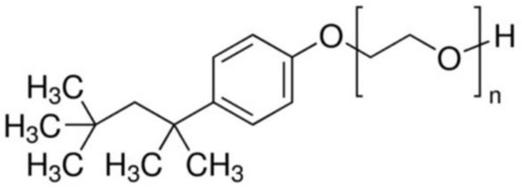
2.1. Lattices Fabrication and Preparation of Trilayer Coatings
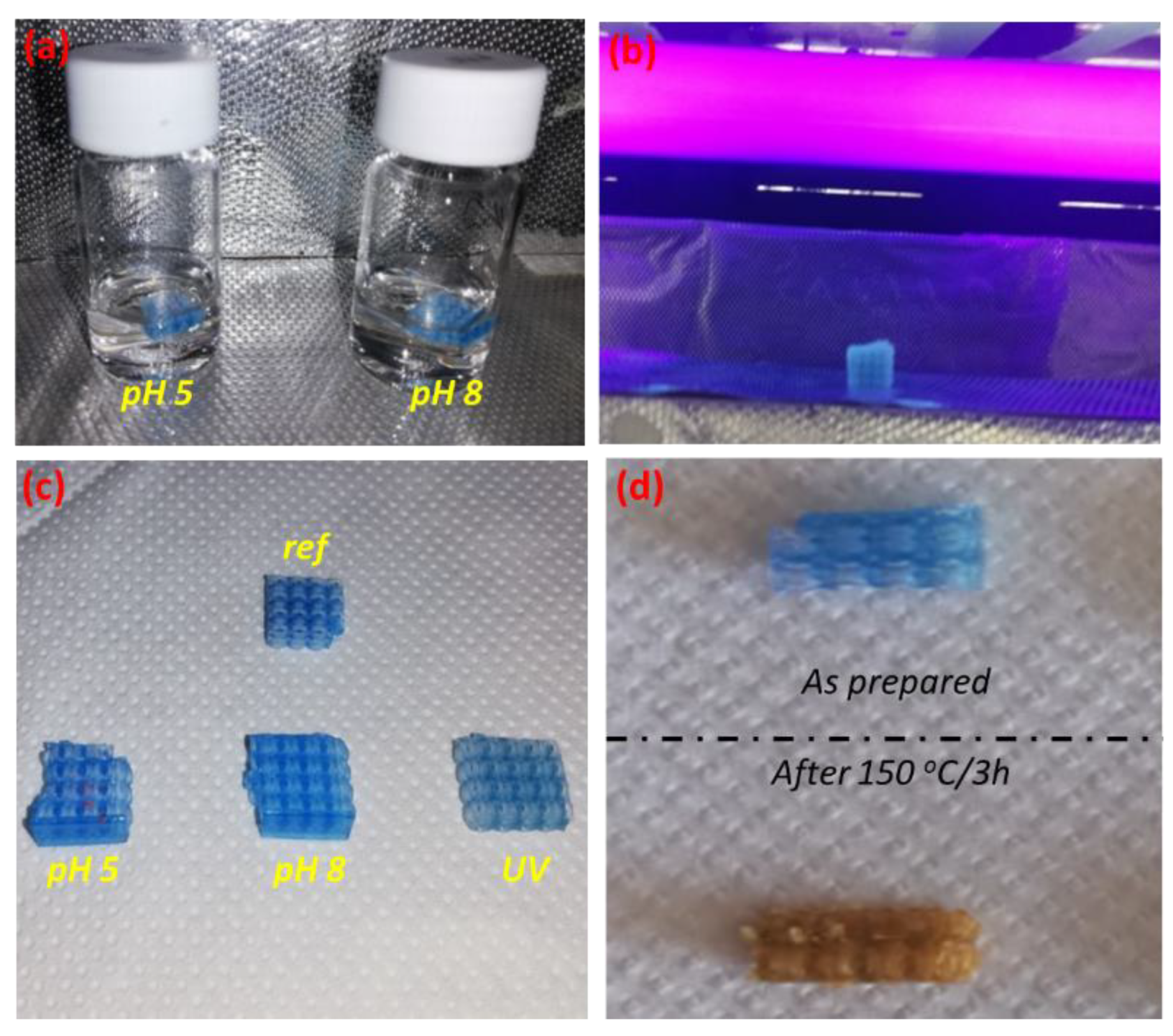
2.2. Accelerated Aging Tests
2.3. Characterization Techniques
2.4. Photocatalytic Performance
3. Results
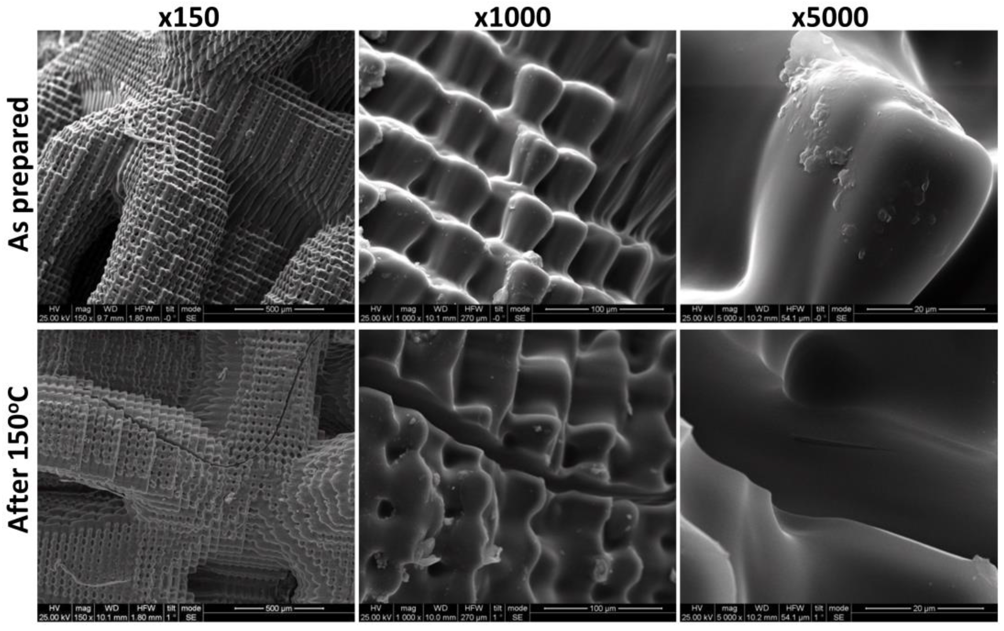
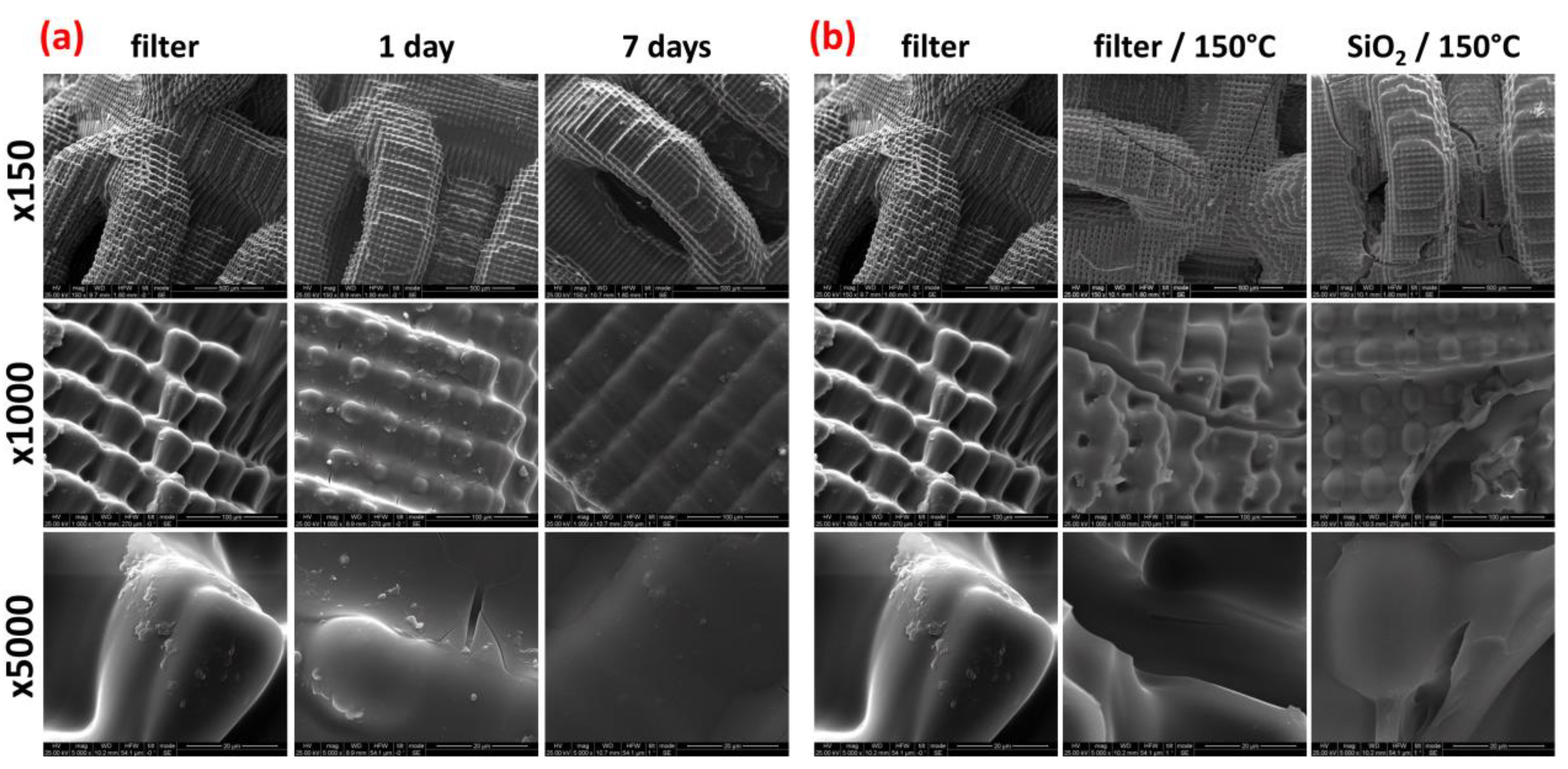
3.1. Accelerated Aging Results
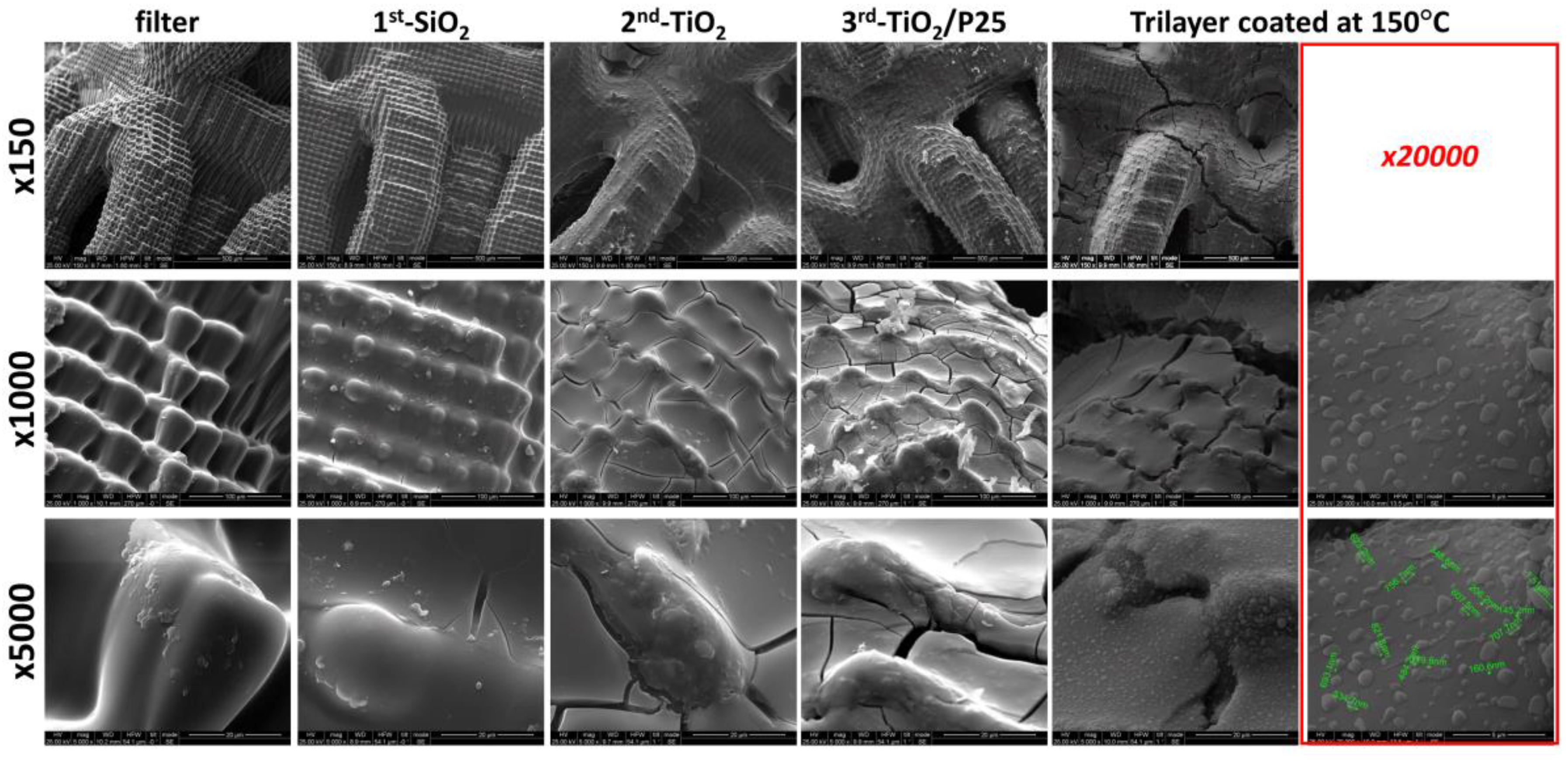
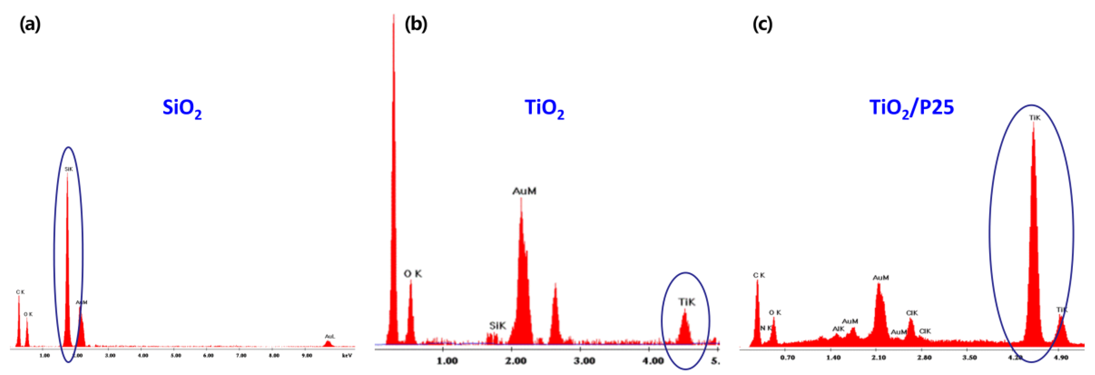
3.2. Morphological Study of the Trilayer Coated Lattices
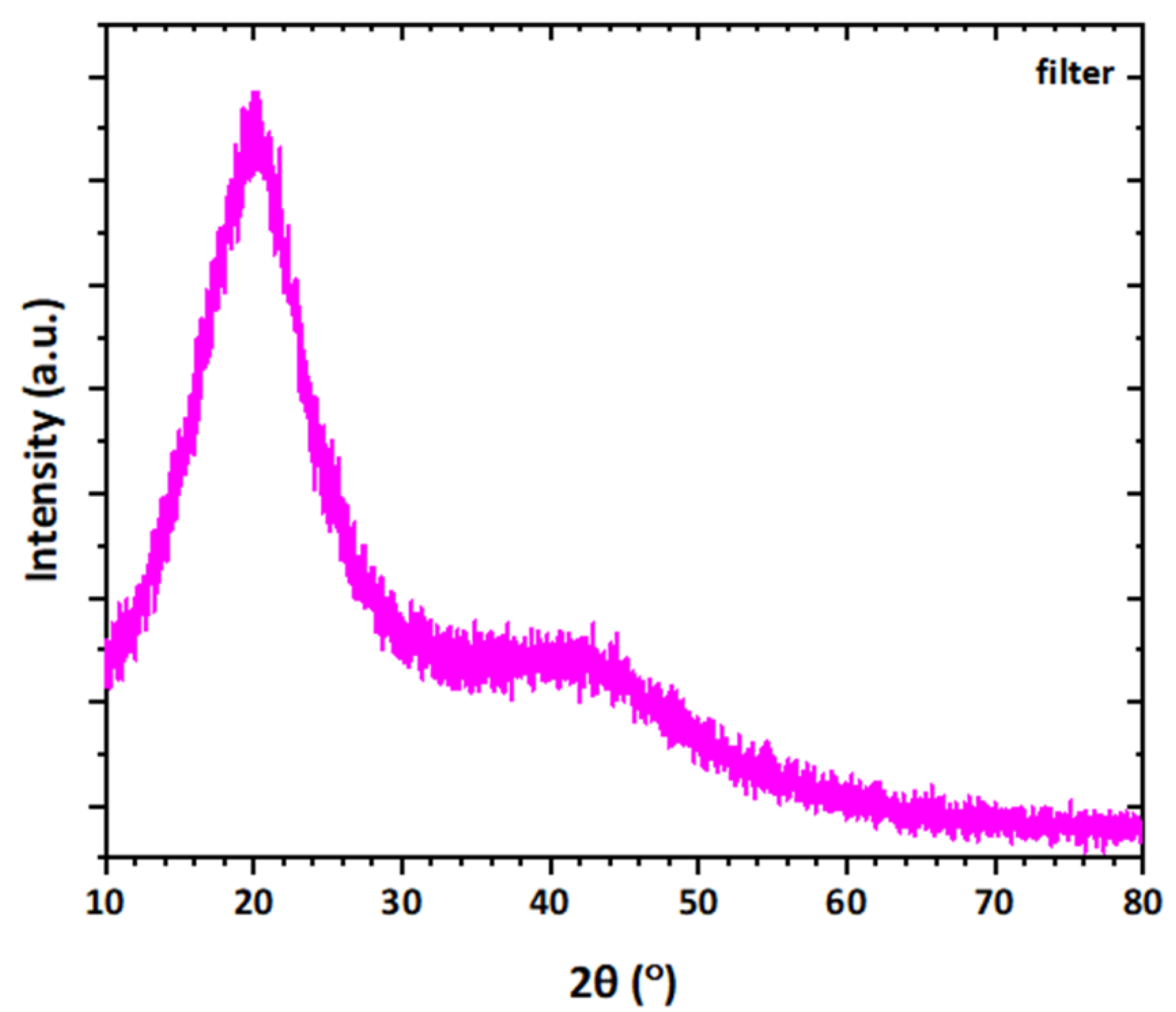
3.3. XRD Analysis
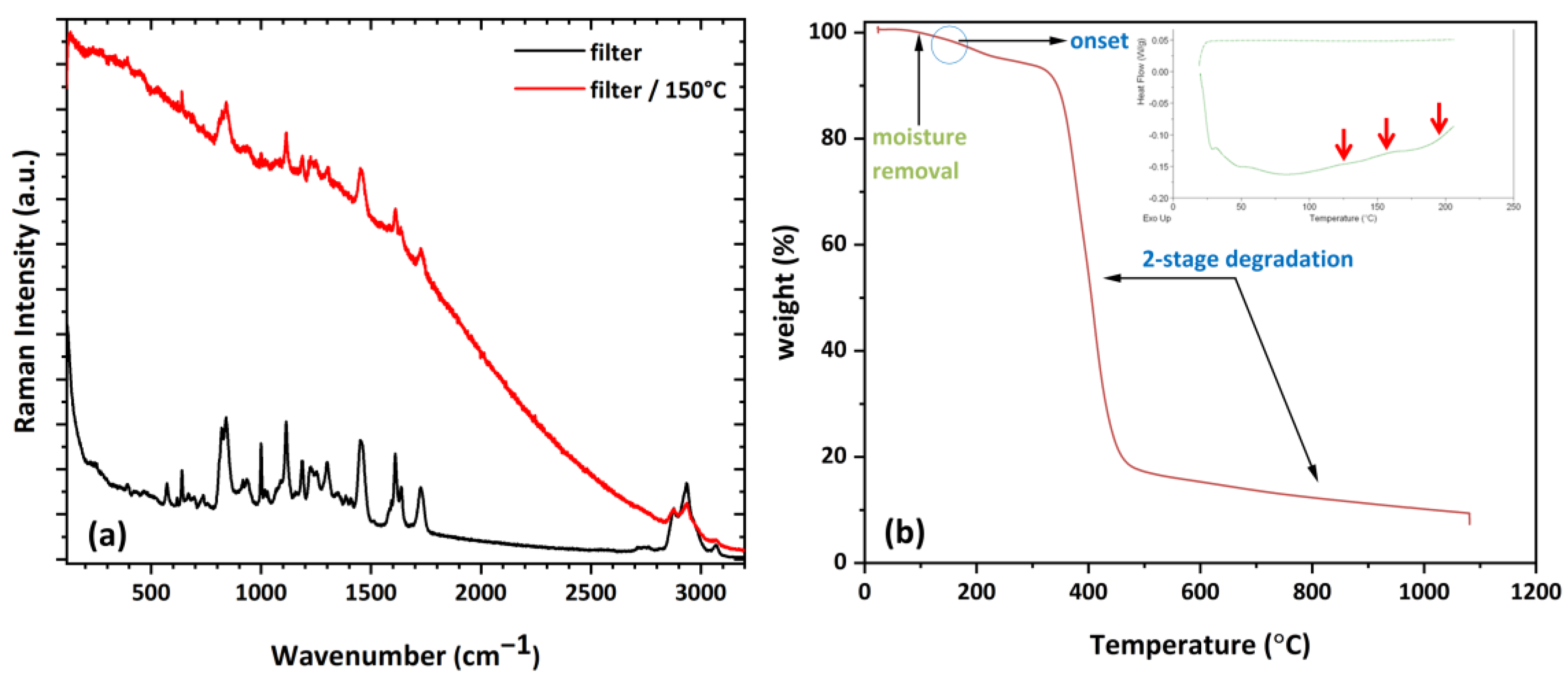
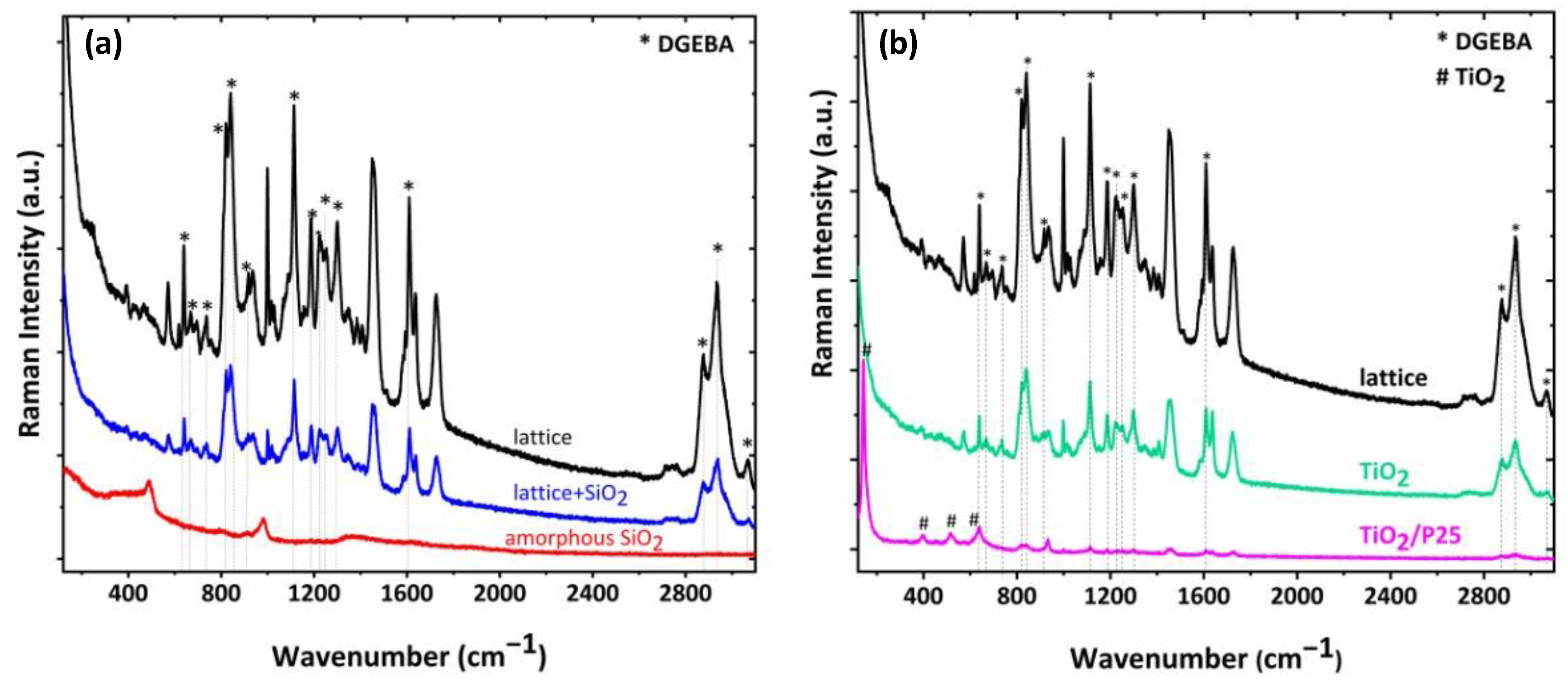
3.4. Raman Analysis
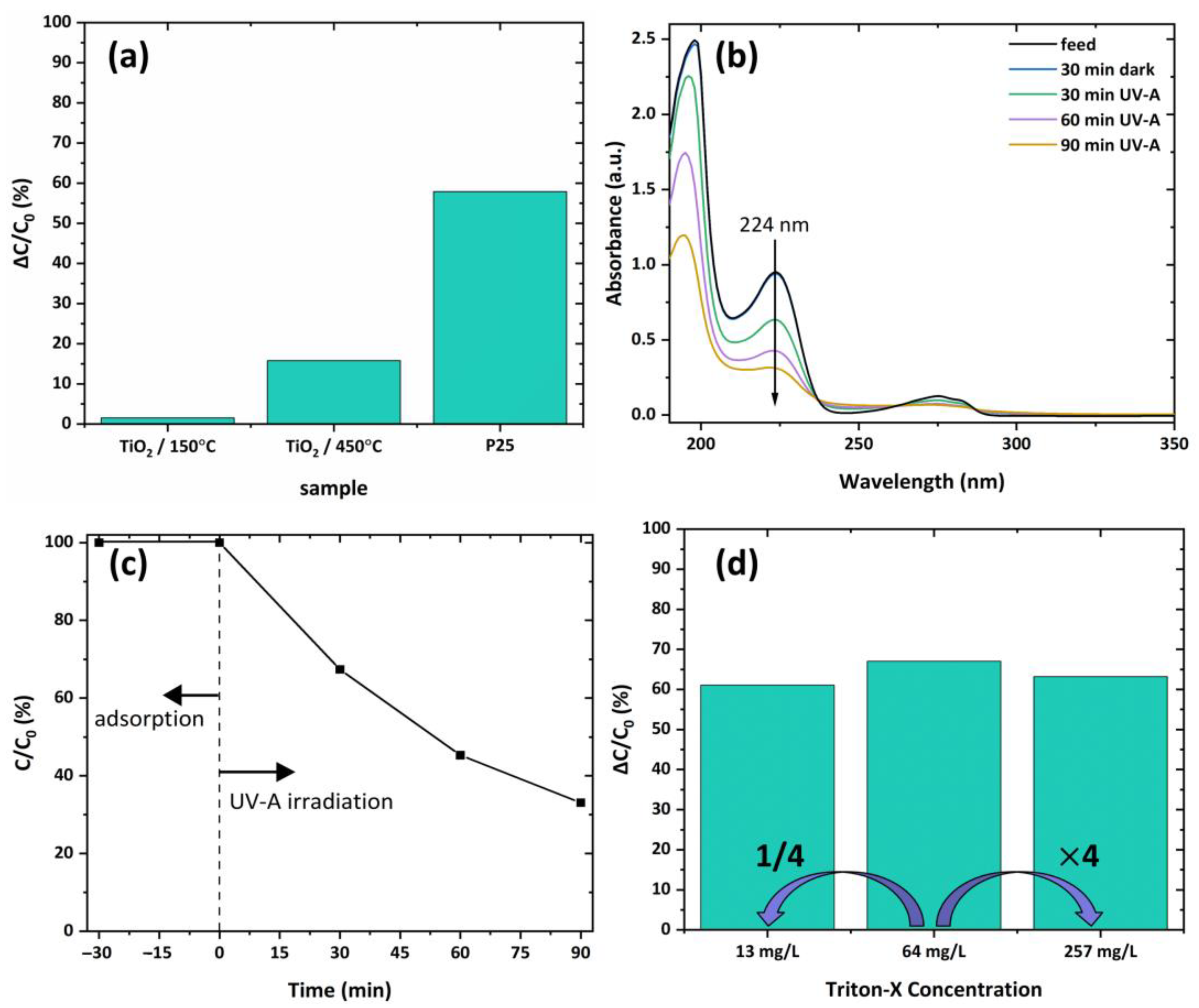
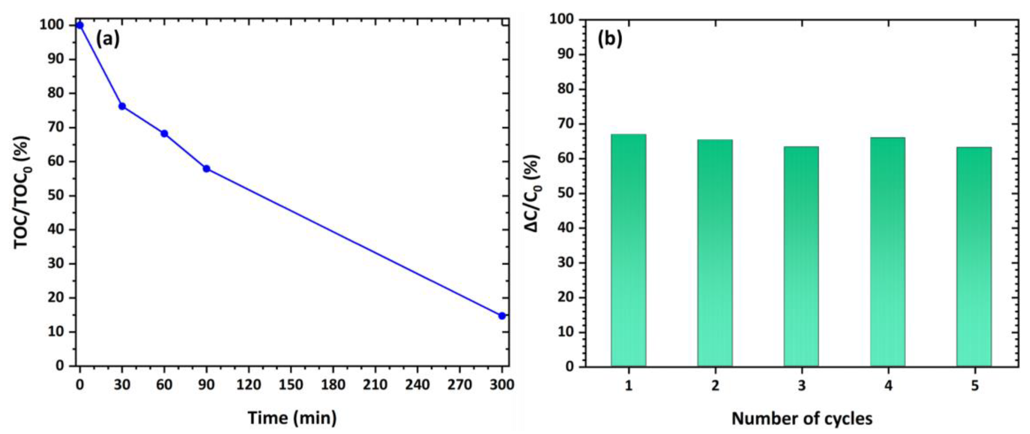
3.5. Photocatalytic Performance
4. Conclusions
Author Contributions
Funding
Data Availability Statement
Conflicts of Interest
References
- Lin, L.; Yang, H.; Xu, X. Effects of Water pollution on human health and disease heterogeneity: A review. Front. Environ. Sci. 2022, 10, 880246. [Google Scholar] [CrossRef]
- Chidiac, S.; El Najjar, ·P.; Ouaini, N.; El Rayess, Y.; El Azzi, D. A comprehensive review of water quality indices (WQIs): History, models, attempts and perspectives. Rev. Environ. Sci. Biotechnol. 2023, 22, 349–395. [Google Scholar] [CrossRef] [PubMed]
- Soares, A. Wastewater treatment in 2050: Challenges ahead and future vision in a European context. Environ. Sci. Ecotechnology 2020, 2, 100030. [Google Scholar] [CrossRef] [PubMed]
- Kesari, K.K.; Soni, R.; Jamal, Q.M.S.; Tripathi, P.; Lal, J.A.; Jha, N.K.; Siddiqui, M.H.; Kumar, P.; Tripathi, V.; Ruokolainen, J. Wastewater treatment and reuse: A review of its applications and health implication. Water Air Soil. Pollut. 2021, 232, 208. [Google Scholar] [CrossRef]
- Subramaniam, M.N.; Goh, P.S.; Kanakaraju, D.; Lim, J.W.; Jye, W.J.; Ismail, A.F. Photocatalytic membranes: A new perspective for persistent organic pollutants removal. Environ. Sci. Pollut. Res. 2022, 29, 12506–12530. [Google Scholar] [CrossRef] [PubMed]
- Sangamnere, R.; Misra, T.; Bherwani, H.; Kapley, A.; Kumar, R. A critical review of conventional and emerging wastewater treatment technologies. Sustain. Water Resour. Manag. 2023, 9, 58. [Google Scholar] [CrossRef]
- Wang, Y.; Wang, C.; Wang, X.; Qin, H.; Lin, H.; Chhuon, K.; Chen, Q. Research progress of tap water treatment process. IOP Conf. Ser. Earth Environ. Sci. 2020, 546, 052025. [Google Scholar] [CrossRef]
- Gao, Q.; Li, J.; Jin, P.; Zheng, J.; Xu, D.; Van der Bruggen, B. The practical application value of a sustainable water purification process is crucial. ACS EST Water 2023, 3, 1990–1993. [Google Scholar] [CrossRef]
- Tian, Y.; Hu, H.; Zhang, J. Solution to water resource scarcity: Water reclamation and reuse. Environ. Sci. Pollut. Res. 2017, 24, 5095–5097. [Google Scholar] [CrossRef] [PubMed]
- Fito, J.; Van Hulle, S.W.H. Wastewater reclamation and reuse potentials in agriculture: Towards environmental sustainability. Environ. Dev. Sustain. 2021, 23, 2949–2972. [Google Scholar] [CrossRef]
- Liao, Z.; Chen, Z.; Xu, A.; Gao, Q.; Song, K.; Liu, J.; Hu, H.-Y. Wastewater treatment and reuse situations and influential factors in major Asian countries. J. Environ. Manag. 2021, 282, 111976. [Google Scholar] [CrossRef] [PubMed]
- Silva, J.A. Water supply and wastewater treatment and reuse in future cities: A systematic literature review. Water 2023, 15, 3064. [Google Scholar] [CrossRef]
- Athanasekou, C.P.; Likodimos, V.; Falaras, P. Recent developments of TiO2 photocatalysis involving advanced oxidation and reduction reactions in water. J. Environ. Chem. Eng. 2018, 6, 7386–7394. [Google Scholar] [CrossRef]
- Nasirian, M.; Lin, Y.P.; Bustillo-Lecompte, C.F.; Mehrvar, M. Enhancement of photocatalytic activity of titanium dioxide using non-metal doping methods under visible light: A review. Int. J. Environ. Sci. Technol. 2018, 15, 2009–2032. [Google Scholar] [CrossRef]
- Chakhtouna, H.; Benzeid, H.; Zari, N.; Qaiss, A.e.k.; Bouhfid, R. Recent progress on Ag/TiO2 photocatalysts: Photocatalytic and bactericidal behaviors. Environ. Sci. Pollut. Res. 2021, 28, 44638–44666. [Google Scholar] [CrossRef] [PubMed]
- Armaković, S.J.; Savanović, M.M.; Armaković, S. Titanium dioxide as the most used photocatalyst for water Purification: An overview. Catalysts 2023, 13, 26. [Google Scholar] [CrossRef]
- Theodorakopoulos, G.; Athanasekou, C.; Romanos, G.E.; Papageorgiou, S.K. Current photocatalytic systems for intensified water purification applications. In Handbook of Smart Photocatalytic Materials, 1st ed.; Hussain, C.M., Mishra, A.K., Eds.; Elsevier: Amsterdam, The Netherlands, 2020; pp. 231–264. [Google Scholar]
- Pelaez, M.; Nolan, N.T.; Pillai, S.C.; Seery, M.K.; Falaras, P.; Kontos, A.G.; Dunlop, P.S.M.; Hamilton, J.W.J.; Byrne, J.A.; O’Shea, K.; et al. A review on the visible light active titanium dioxide photocatalysts for environmental applications. Appl. Catal. B-Environ. 2012, 125, 331–349. [Google Scholar] [CrossRef]
- Moustakas, N.G.; Katsaros, F.K.; Kontos, A.G.; Romanos, G.E.; Dionysiou, D.D.; Falaras, P. Visible light active TiO2 photocatalytic filtration membranes with improved permeability and low energy consumption. Catal. Today 2014, 224, 56–69. [Google Scholar] [CrossRef]
- Athanasiou, D.A.; Romanos, G.E.; Falaras, P. Design and optimization of a photocatalytic reactor for water purification combining optical fiber and membrane technologies. Chem. Eng. J. 2016, 305, 92–103. [Google Scholar] [CrossRef]
- Nakano, K.; Obuchi, E.; Takagi, S.; Yamamoto, R.; Tanizaki, T.; Taketomi, M.; Eguchi, M.; Ichida, K.; Suzuki, M.; Hashimoto, A. Photocatalytic treatment of water containing dinitrophenol and city water over TiO2/SiO2. Sep. Purif. Technol. 2004, 34, 67–72. [Google Scholar] [CrossRef]
- Mozia, S.; Brożek, P.; Przepiórski, J.; Tryba, B.; Morawski, A.W. Immobilized TiO2 for phenol degradation in a pilot-scale photocatalytic reactor. J. Nanomater. 2012, 2012, 949764. [Google Scholar] [CrossRef]
- Rezaei, M.; Rashidi, F.; Royaee, S.J.; Jafarikojour, M. Performance evaluation of a continuous flow photocatalytic reactor for wastewater treatment. Environ. Sci. Pollut. Res. 2014, 21, 12505–12517. [Google Scholar] [CrossRef] [PubMed]
- Jawad, A.H.; Mubarak, N.S.A.; Ishak, M.A.M.; Ismail, K.; Nawawi, W.I. Kinetics of photocatalytic decolourization of cationic dye using porous TiO2 film. J. Taibah Univ. Sci. 2016, 10, 352–362. [Google Scholar] [CrossRef]
- Abdel-Maksoud, Y.; Imam, E.; Ramadan, A. TiO2 solar photocatalytic reactor systems: Selection of reactor design for scale-up and commercialization—Analytical review. Catalysts 2016, 6, 138. [Google Scholar] [CrossRef]
- Phan, D.D.; Babick, F.; Trịnh, T.H.T.; Nguyen, M.T.; Samhaber, W.; Stintz, M. Investigation of fixed-bed photocatalytic membrane reactors based on submerged ceramic membranes. Chem. Eng. Sci. 2018, 191, 332–342. [Google Scholar] [CrossRef]
- Al-Mamun, M.R.; Kader, S.; Islam, M.S. Solar-TiO2 immobilized photocatalytic reactors performance assessment in the degradation of methyl orange dye in aqueous solution. Environ. Nanotechnol. Monit. Manag. 2021, 16, 100514. [Google Scholar]
- Wang, D.; Mueses, M.A.; Márquez, J.A.C.; Machuca-Martínez, F.; Grčić, I.; Moreira, R.P.M.; Li Puma, G. Engineering and modeling perspectives on photocatalytic reactors for water treatment. Water Res. 2021, 202, 117421. [Google Scholar] [PubMed]
- Le, C.; Wismer, M.K.; Shi, Z.-C.; Zhang, R.; Conway, D.V.; Li, G.; Vachal, P.; Davies, I.W.; MacMillan, D.W.C. A general small-scale reactor to enable standardization and acceleration of photocatalytic reactions. ACS Cent. Sci. 2017, 3, 647–653. [Google Scholar] [CrossRef] [PubMed]
- Janczarek, M.; Kowalska, E. Computer simulations of photocatalytic reactors. Catalysts 2021, 11, 198. [Google Scholar] [CrossRef]
- Ballari, M.d.l.M.; Alfano, O.M.; Cassano, A.E. Mass transfer limitations in slurry photocatalytic reactors: Experimental validation. Chem. Eng. Sci. 2010, 65, 4931–4942. [Google Scholar] [CrossRef]
- Yao, Y.; Zheng, Y.; Yang, Y. Numerical simulation of energy and mass transfer in a magnetic stirring photocatalytic reactor. Sustainability 2023, 15, 7604. [Google Scholar] [CrossRef]
- Xiao, M.; Wang, Z.; Maeda, K.; Liu, G.; Wang, L. Addressing the stability challenge of photo(electro) catalysts towards solar water splitting. Chem. Sci. 2023, 14, 3415. [Google Scholar] [CrossRef] [PubMed]
- Alalm, M.G.; Djellabi, R.; Meroni, D.; Pirola, C.; Bianchi, C.L.; Boffito, D.C. Toward scaling-up photocatalytic process for multiphase environmental applications. Catalysts 2021, 11, 562. [Google Scholar] [CrossRef]
- Isopencu, G.O.; Mocanu, A.; Deleanu, I.-M. A brief review of photocatalytic reactors used for persistent pesticides degradation. ChemEngineering 2022, 6, 89. [Google Scholar] [CrossRef]
- Yang, H.; Lee, Y.-J.; Park, S.-J.; Lee, C.-G. Exploring the viability of a foating photocatalyst in a continuous stirred tank reactor system for continuous water treatment. Environ. Sci. Pollut. Res. 2023, 30, 114582–114590. [Google Scholar] [CrossRef] [PubMed]
- Ye, L.; Zhang, Y.; Zhang, X.; Hu, T.; Ji, R.; Ding, B.; Jiang, B. Sol–gel preparation of SiO2/TiO2/SiO2–TiO2 broadband antireflective coating for solar cell cover glass. Sol. Energy Mater. Sol. Cells 2013, 111, 160–164. [Google Scholar] [CrossRef]
- Du, P.; Carneiro, J.T.; Moulijn, J.A.; Mul, G. A novel photocatalytic monolith reactor for multiphase heterogeneous photocatalysis. Appl. Catal. A: Gen. 2008, 334, 119–128. [Google Scholar] [CrossRef]
- Vodišek, N.; Ramanujachary, K.; Brezová, V.; Štangar, U.L. Transparent titania-zirconia-silica thin films for self-cleaning and photocatalytic applications. Catal. Today 2017, 287, 142–147. [Google Scholar]
- Theodorakopoulos, G.V.; Arfanis, M.K.; Sánchez Pérez, J.A.; Agüera, A.; Cadena Aponte, F.X.; Markellou, E.; Romanos, G.E.; Falaras, P. Novel pilot-scale photocatalytic nanofiltration reactor for agricultural wastewater treatment. Membranes 2023, 13, 202. [Google Scholar] [CrossRef] [PubMed]
- de Andrade, J.E.; Machado, R.; Macêdo, M.A.; Cunha, C.; Guilherme, F. AFM and XRD characterization of silver nanoparticles films deposited on the Surface of DGEBA epoxy resin by ion sputtering. Polímeros 2013, 23, 19–23. [Google Scholar] [CrossRef]
- Farquharson, S.; Smith, W.W.; Rose, J.; Shaw, M. Correlations between molecular (raman) and macroscopic (rheology) data for process monitoring of thermoset composites. JPACSM Process Anal. Chem. 2002, 7, 45–53. [Google Scholar]
- Degioanni, S.; Jurdyc, A.M.; Cheap, A.; Champagnon, B.; Bessueille, F.; Coulm, J.; Bois, L.; Vouagne, D. Surface-enhanced Raman scattering of amorphous silica gel adsorbed on gold substrates for optical fiber sensors. J. Appl. Phys. 2015, 118, 153103. [Google Scholar] [CrossRef]
- Arfanis, M.K.; Adamou, P.; Moustakas, N.G.; Triantis, T.M.; Kontos, A.G.; Falaras, P. Photocatalytic degradation of salicylic acid and caffeine emerging contaminants using titania nanotubes. Chem. Eng. J. 2017, 310, 525–536. [Google Scholar] [CrossRef]
- Saien, J.; Ojaghloo, Z.; Soleymani, A.R.; Rasoulifard, M.H. Homogeneous and heterogeneous AOPs for rapid degradation of Triton X-100 in aqueous media via UV light, nano titania hydrogen peroxide and potassium persulfate. Chem. Eng. J. 2011, 167, 172–182. [Google Scholar] [CrossRef] [PubMed]
Disclaimer/Publisher’s Note: The statements, opinions and data contained in all publications are solely those of the individual author(s) and contributor(s) and not of MDPI and/or the editor(s). MDPI and/or the editor(s) disclaim responsibility for any injury to people or property resulting from any ideas, methods, instructions or products referred to in the content. |
© 2024 by the authors. Licensee MDPI, Basel, Switzerland. This article is an open access article distributed under the terms and conditions of the Creative Commons Attribution (CC BY) license (https://creativecommons.org/licenses/by/4.0/).
Share and Cite
Theodorakopoulos, G.V.; Arfanis, M.K.; Stepišnik Perdih, T.; Malamis, S.; Iatrou, D.; Romanos, G.E.; Falaras, P. Innovative Photocatalytic Reactor for Sustainable Industrial Water Decontamination: Utilizing 3D-Printed Components and Silica-Titania Trilayer Coatings. Environments 2024, 11, 156. https://doi.org/10.3390/environments11070156
Theodorakopoulos GV, Arfanis MK, Stepišnik Perdih T, Malamis S, Iatrou D, Romanos GE, Falaras P. Innovative Photocatalytic Reactor for Sustainable Industrial Water Decontamination: Utilizing 3D-Printed Components and Silica-Titania Trilayer Coatings. Environments. 2024; 11(7):156. https://doi.org/10.3390/environments11070156
Chicago/Turabian StyleTheodorakopoulos, George V., Michalis K. Arfanis, Tadej Stepišnik Perdih, Simos Malamis, Dimitrios Iatrou, George Em. Romanos, and Polycarpos Falaras. 2024. "Innovative Photocatalytic Reactor for Sustainable Industrial Water Decontamination: Utilizing 3D-Printed Components and Silica-Titania Trilayer Coatings" Environments 11, no. 7: 156. https://doi.org/10.3390/environments11070156