Article

Uplink Transmit Power Control for Single-Carrier Grouped FDMA with Iterative Multiuser Detection

1
Samsung Electronics Co., Ltd, Suwon, Gyeonggi 16545, Korea
2
R&D Center, LG Display, Paju, Gyeonggi 10845, Korea
3
Department of Electronics, Information and Communication Engineering, Mokpo National University, Muan, Jeonnam 58554, Korea
*
Author to whom correspondence should be addressed.
Appl. Sci. 2020, 10(1), 119; https://doi.org/10.3390/app10010119
Submission received: 25 September 2019 / Revised: 25 November 2019 / Accepted: 18 December 2019 / Published: 22 December 2019
(This article belongs to the Section Electrical, Electronics and Communications Engineering)

Abstract

:
We consider an uplink power allocation scheme for single-carrier frequency-division multiple access (FDMA) with iterative multiuser detection, called single-carrier grouped FDMA (SC-GFDMA). SC-GFDMA is a non-orthogonal scheme in which several users share a single time-frequency resource. Hence, the uplink signal of a user can be regarded as both a signal and a source of interference. The signal power of each user should be sufficiently high to ensure reliable signal detection and sufficiently low to suppress inter-user interference. That is, the transmit power of each user should be adjusted appropriately to achieve high spectral efficiency. In this context, a power control method for an uplink SC-GFDMA system is proposed by analyzing the signal-to-interference-plus-noise ratios of users sharing each time-frequency resource. In particular, the uplink spectral efficiency is improved by limiting the transmit power of each user according to a criterion derived using a semi-analytic method called signal-to-noise ratio-variance density evolution. Simulation results demonstrate that the proposed method can significantly increase the spectral efficiency of the system, even with a considerably reduced total transmit power.

1. Introduction

Single-carrier frequency-division multiple access (SC-FDMA), based on single-carrier modulation with frequency-domain equalization (SC-FDE) [1], is an uplink data transmission scheme for broadband wireless systems; it has a low peak-to-average-power ratio (PAPR) and has therefore been considered to be a replacement for orthogonal frequency-division multiple access (OFDMA), depending on the system parameters [2,3,4,5,6,7]. SC-FDMA is also called “linearly precoded OFDMA” because it has an additional discrete Fourier transform (DFT) stage prior to the OFDMA structure. The low-PAPR characteristic of SC-FDMA benefits the uplink scheme of mobile user equipment by reducing the transmit power and the cost of manufacturing a power amplifier. In addition, the implementation and computational complexities of SC-FDMA are concentrated at the receiver end. Application of SC-FDMA to an uplink is advantageous in this regard, because the receiver is located at a base station (BS). Accordingly, the Third-Generation Partnership Project Long-Term Evolution (3GPP-LTE) adopted SC-FDMA for uplink data transmission. Recently, SC-FDMA was also adopted in various major applications of 4th-generation (4G) LTE advanced (LTE-A) and 5th-generation (5G) new radio networks [8,9] including heterogeneous networks [10,11], multiple input and multiple output [12,13,14], machine-type communications [15,16], and green communications [17].
The demand for wireless communication increased rapidly through the implementation of 4G and 5G. As the spectrum and power are limited resources, an improvement in spectral efficiency has always been a crucial challenge in wireless communication. To improve the spectral efficiency of SC-FDMA, a non-orthogonal multiple access scheme called single-carrier grouped FDMA (SC-GFDMA) was proposed, which is SC-FDMA with iterative multiuser detection (IMD) [5]. SC-GFDMA allocates a common set of subcarriers to several users simultaneously, rather than to only one user as in a typical SC-FDMA scheme. The sharing of a frequency band is a non-orthogonal feature that causes multiple access interference (MAI) [5,6,7,18]. MAI can be efficiently eliminated through IMD; hence, SC-GFDMA can achieve higher spectral efficiency than that achieved by typical SC-FDMA, FDMA, OFDMA, and time-division multiple access systems [5]. Specifically, SC-GFDMA increases the spectral efficiency achieved in each time-frequency resource grid, which is called a subcarrier chunk in this paper, by stacking up users in each chunk (Figure 1); here, a chunk refers to a set of consecutive subcarriers and corresponds to the minimum unit of resource allocation in each frame, such as a physical resource block in LTE/LTE-A standards [8,9].
In other words, SC-GFDMA increases the spectral efficiency achieved in each chunk without using additional time, frequency, and spatial resources. In terms of addressing the demand for higher-speed wireless communication with limited communication resources, SC-GFDMA can be a solution for future standards, as it enhances the performance of communication building blocks. In addition, SC-GFDMA inherits the low-PAPR characteristic and simple single-tap equalizer from SC-FDMA; the transmitter also has a similar structure to that of SC-FDMA, except for the user-specific interleaver. Thus, SC-GFDMA can be considered to be an alternative to SC-FDMA for uplink transmission in future wireless standards. The primary drawback of using SC-GFDMA (when compared with SC-FDMA) is the additional computational complexity imposed on the receiver side. In uplink transmission, this additional cost is on the BS side, and BS is generally more robust and can support more complex computations than user equipment can. Nevertheless, commercial network operators should consider a trade-off between the additional cost for higher computational complexity and the increase in spectral efficiency when implementing SC-GFDMA schemes.
In typical SC-FDMA systems, multiple users are orthogonally allocated in the frequency domain such that a single user is solely served in each chunk. Thus, studies on user scheduling for SC-FDMA have commonly attempted to select the user having the highest signal-to-interference-plus-noise ratio (SINR) [19,20], to increase the spectral efficiency in each chunk. More sophisticated resource allocation techniques were commonly considered at subframe or frame level across subcarriers or chunks [11,13,16,21,22]. In contrast, in SC-GFDMA, multiple users access each chunk simultaneously while different groups of users are allocated in different chunks based on the FDMA criterion (Figure 1). Thus, resource allocation significantly affects the available spectral efficiency in each chunk. The scheduling methods for SC-GFDMA should be designed to achieve high spectral efficiency in each chunk while guaranteeing acceptable quality-of-service (QoS) to all scheduled users. For example, the study in [23] proposed a pattern-aware user scheduling algorithm that efficiently exploits the non-orthogonal nature of SC-GFDMA, and thus, it achieved near-optimal spectral efficiency for the given transmit power. Moreover, as there is interference among the received signals of multiple users in each chunk, the use of a higher transmit power for each user does not always correspond to a higher total spectral efficiency in each chunk. Therefore, a sophisticated algorithm should be additionally considered to optimize the transmit powers of users in each chunk. That is, the transmit power of each user should be sufficiently high to ensure reliable detection, but sufficiently low to restrict interference with other users. A previous study on SC-GFDMA demonstrated that the scheduling complexity could be decreased when QoS-satisfied users have unequal powers [7]. A low-complexity scheduling algorithm that exploits these properties was introduced in [7], but it achieved a relatively low spectral efficiency at the cost of low complexity of implementation. Moreover, the unequal transmit powers of users were not designed with a specific power control strategy. Owing to the non-orthogonal characteristic, it is difficult to derive explicit mathematical expressions for the performance achieved using the SC-GFDMA structure. Thus, there is a need for power allocation algorithms that can exploit the essential benefits of SC-GFDMA to enhance the performance in each chunk. Various studies on power control for SC-FDMA-based systems [10,11,24,25] were reported previously. However, to the best of our knowledge, a specific power control method applicable to each chunk of the SC-GFDMA structure has not been considered yet. This specificity of the power control method is the focus of this study.
In this paper, a power control algorithm that exploits the fundamental structure of SC-GFDMA is proposed to increase the spectral efficiency available in each chunk. The proposed algorithm optimizes the transmit powers of users allocated in each chunk based on a criterion derived from the SINR analysis of the users. First, a maximization problem of the spectral efficiency is formulated in each chunk and is modified to a simplified form. Subsequently, we present an appropriate solution for the power control problem by analyzing the successive SINRs of the users during the IMD, based on a semi-analytic method called signal-to-noise ratio (SNR)-variance density evolution. Consequently, the uplink transmit power of each user is intentionally restricted to reduce its effect as MAI to the signals of other users. Specifically, we place users in the same chunk in the decreasing order of SINR. Then, we demonstrate that the reliable detection of the kth user is closely related to the SINR of the ( k + 2 ) th user. Accordingly, we argue that it is desirable to have a sequential relation of SINRs of ordered users with a consistent relation between consecutive users. In this context, we consider a geometric sequence of the controlled powers of users in the same chunk. The common ratio of the geometric sequence is a design parameter of the proposed power control scheme, and an optimal ratio can be derived from the SINR analysis based on SNR-variance density evolution. The proposed method with the optimized common ratio achieves a significantly higher spectral efficiency than that achieved by the conventional SC-GFDMA and SC-FDMA systems, even with a reduced total transmit power. Compared to the previous studies, the novel observations of this paper can be summarized as follows:
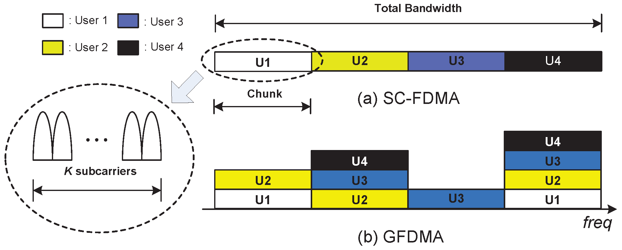
  • A specific power control algorithm that exploits the non-orthogonal structure of SC-GFDMA is designed to increase the available spectral efficiency in each chunk.
  • Based on the SNR-variance density evolution, we provide a tractable analysis of SINR of users during the IMD.
  • The proposed power control significantly increases the spectral efficiency in each chunk.
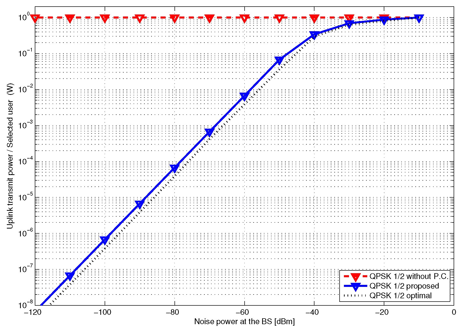
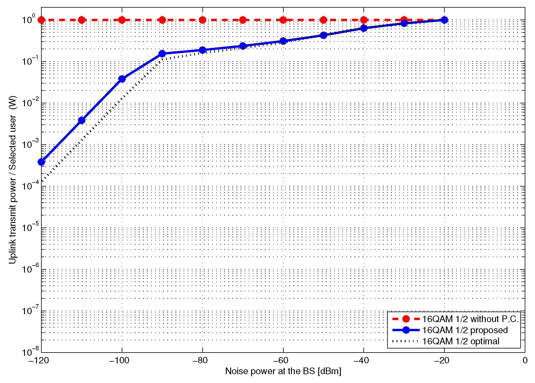
  • The proposed power control efficiently reduces (transmit) power consumption at each chunk compared with the conventional SC-GFDMA schemes without power control.
The primary symbols used in this paper are summarized in Table 1, and some notations used in this paper are summarized as follows.
Notation: F K is the normalized K × K DFT matrix, whose ( n + 1 , k + 1 ) th entry is 1 / K e i 2 π n k / K for n , k = 0 , 1 , , K 1 , where i = 1 ; 0 M × N and 1 M × N are all-zero and all-one matrices of size M × N , respectively; I K is the K × K identity matrix; e n = [ 0 1 × ( n 1 ) 1 0 1 × ( K n ) ] T is a K × 1 unit vector with 1 as the nth element and 0 as the remaining elements; Pr ( · ) indicates the probability of an event, and E ( · ) and Cov ( · ) are the expectation and covariance operators, respectively; ( · ) * , ( · ) T , ( · ) H , and [ · ] n denote the complex conjugate, transpose, conjugate transpose, and nth entry of a vector, respectively; Diag ( c ) , for a vector c , produces a diagonal matrix whose diagonal entries correspond to c in the same order.

2. System Model

In this study, we consider an SC-GFDMA system based on SC-FDMA with localized subcarrier mapping. In this system, different users occupy different frequency chunks, and each chunk is occupied by a single user [4] (Figure 1a); here, a chunk is defined as a set of K consecutive subcarriers in the frequency domain during each time slot (Time slot refers to the length of time used to transmit all subcarriers simultaneously, as defined in LTE/LTE-A standards [26]. In [4], the same measure was denoted as a “block”.). In contrast, SC-GFDMA allows the sharing of a chunk by multiple users (Figure 1b), and thus, it has a non-orthogonal characteristic among user signals. The scheduler determines the allocation of users in each chunk, and the number of users sharing each chunk can be different. Power control and user scheduling are performed chunk-by-chunk by regarding each chunk as the minimum unit of resource allocation. By using channel-dependent power control and scheduling, the spectral efficiency can be significantly increased in each chunk, which is the primary objective of this study.
In summary, we consider an uplink SC-GFDMA system based on localized subcarrier mapping, in which a BS communicates with U users. Based on the GFDMA criterion, U m users access the same chunk m, for m = 1 , , M , where M is the total number of chunks in the frequency domain during each time slot. The scheduler is allowed to map one user to multiple chunks (Figure 1). Thus, we have U m = 1 M U m . As each chunk consists of K consecutive subcarriers, the total frequency bandwidth is divided into M K subcarriers. Before transmitting uplink data, the BS adjusts the transmit powers of the users in each chunk, depending on the estimated uplink channels, and then schedules appropriate users in each chunk from the total user set U = { 1 , , U } . Subsequently, the BS sends the information of both adjusted powers and scheduling results to the associated users through a control plane. The detailed procedures for power control and scheduling will be further discussed in Section II-C. The data streams of each user are sent on the associated chunk through a data plane, based on the control plane information.

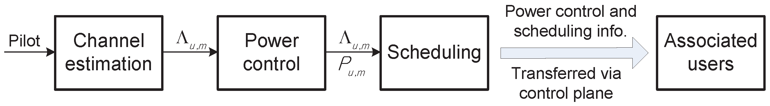
2.1. Transmitter and Receiver Principles for Data Plane

Let U m be the set of users allocated to the chunk m ( U m = | U m | ), and further let X u , m = [ X u , m ( 1 ) X u , m ( 2 ) X u , m ( K ) ] T be the frequency-domain transmit block for user u at chunk m. As the SC-GFDMA shares each chunk to multiple users (Figure 1), the frequency-domain received signal is given by
Y = m = 1 M u U m L u P u , m Λ u L m X u , m + W ,
where Λ u is an N × N diagonal matrix consisting of the channel frequency responses of user u, and W is an N × 1 additive white Gaussian noise (AWGN) vector whose entries are i.i.d. complex Gaussian random variables with zero mean and variance σ N 2 . The subcarrier mapping matrix L m for chunk m is defined as L m = [ 0 K × ( m 1 ) K I K × K 0 K × ( N m K ) ] T , such that [ L m X u , m ] ( m 1 ) K + k = X u , m ( k ) , for k = 1 , , K , where N = M K is the total number of subcarriers in the frequency domain. P u , m is the transmit power of user u at chunk m and L u is the free-space pathloss from the BS to user u. We assume that the pathloss has a simple far-field expression, i.e.,
L u = c 4 π d u f c 2 ,
where d u is the distance between the BS and the user u, c is the speed of light, and f c is the center frequency. The transmit power P u , m is constrained by the maximum transmit energy 1 W = 30 dBm such that
P u , m 1 ,
for u = 1 , , U , and m = 1 , , M . From (1), the frequency-domain received signal Y m at chunk m is expressed as
Y m = L m T Y = l = 1 M u U l L u P u , l L m T Λ u L l X u , l + L m T W
= ( a ) u U m L u P u , m Λ u , m X u , m + W m ,
where Λ u , m L m T Λ u L m is a K × K diagonal matrix consisting of the channel frequency response of user u at chunk m; the ( k , k ) th entry of Λ u , m is denoted as Λ u , m ( k ) , for k = 1 , , K . Furthermore, W m L m T W is a K × 1 complex AWGN vector with the covariance matrix σ N 2 I K , and (a) follows because L m = [ 0 K × ( m 1 ) K I K × K 0 K × ( N m K ) ] T .
Our SC-GFDMA structure uses IMD, which performs successive multiuser interference cancelation (MUIC) at each iteration. With MUIC, the frequency-domain received signal from user u is recovered by canceling MAI at each iteration. Thus, based on successive MUIC, the received signal of user u at chunk m can be computed as [7]
Z u , m = L u P u , m Λ u , m X u , m + u U m , u u L u P u , m Λ u , m ( X u , m X ¯ u , m ) + W m ,
at each iteration of the IMD, where X ¯ u , m = F K x ¯ u , m , with X ¯ u , m [ X ¯ u , m ( 1 ) X ¯ u , m ( 2 ) X ¯ u , m ( K ) ] T , and x ¯ u , m = [ x ¯ u , m ( 1 ) x ¯ u , m ( 2 ) x ¯ u , m ( K ) ] T ; x ¯ u , m ( n ) is the mean of the transmitted symbols and is calculated at the decoder.
With MUIC, the one-tap frequency-domain weight of the minimum-mean-square error (MMSE)-FDE and the corresponding equalized symbol were derived in [6]. Specifically, the one-tap frequency-domain weight can be represented as
G u , m ( k ) = L u P u , m Λ u , m ( k ) u U m L u P u , m ν u , m | Λ u , m ( k ) | 2 + σ N 2 ,
and the frequency-domain equalized symbol is obtained as
X ^ u , m ( k ) = G u , m * ( k ) Z u , m ( k ) + ( μ u , m G u , m * ( k ) L u P u , m Λ u , m ( k ) ) X ¯ u , m ( k ) ,
for each k = 1 , , K , where Z u , m ( k ) = [ Z u , m ] k and the mean μ u , m is defined as
μ u , m 1 K k = 1 K G u , m * ( k ) L u P u , m Λ u , m ( k ) .
The average variance ν u , m is obtained as
ν u , m 1 K n = 1 K ν u , m ( n ) ,
where
ν u , m = cov ( x u , m ( n ) x u , m ( n ) )
= q = 0 2 Q 1 | α q | 2 · P ( x u , m ( n ) = α q ) | x ¯ u , m ( n ) | 2 ,
where x ¯ u , m ( n ) is the nth time-domain mean sample from the decoder, and Q is the modulation level and α q is symbol alphabet.
The fundamental principles of SC-GFDMA are well presented in [5,7]. For the entire transmitter and receiver block diagrams of SC-GFDMA with a user-specific interleaver and a subcarrier mapper, readers are referred to Figure 2 in [7].

2.2. SNR-Variance Density Evolution

In this study, a semi-analytic method called SNR-variance density evolution is used to evaluate the SNR of users during the IMD [7,27,28]. With SNR-variance density evolution, the process of the IMD is modeled by using two local processors; an equalizer and a decoder (Figure 3 in [7]). The equalizer outputs an SNR by considering the variance from the output of the decoder as an input parameter and conversely, the decoder outputs a variance by using the SNR from the equalizer output as an input value. The SNR-variance density evolution models the input-output relation of each local processor as a function that can be numerically obtained through simulation.
Let x ^ u , m ( n ) be the time-domain equalized symbol at time n, i.e., x ^ u , m = F K 1 X ^ u , m with x ^ u , m [ x ^ u , m ( 1 ) x ^ u , m ( 2 ) x ^ u , m ( K ) ] T . Then, from [7], the SNR of x ^ u , m ( n ) is given by
Γ x ^ u , m ( n ) = μ u , m 2 μ u , m ν u , m μ u , m 2 .
As Γ x ^ u , m ( n ) is invariant with respect to n, we use the notation: Γ u , m Γ x ^ u , m ( n ) . Moreover, as the variance is calculated based on the a priori log-likelihood ratios from the MAP decoder [7], the variance is given by a function of SNR, which is denoted as ν u , m ( n ) = f ( Γ u , m ) . As Γ u , m is invariant with respect to n, we have
ν u , m = f ( Γ u , m ) .
Similarly, the bit error rate (BER) performance is also expressed as a function of SNR as follows:
B E R = h ( Γ u , m ) .
Because the functions f ( · ) and h ( · ) do not have closed-form expressions, they are generally estimated by using Monte Carlo simulation. That is, they should be numerically obtained offline by simulating the decoder performance over an AWGN channel for quantized values of SNR; one may construct a lookup table for the quantized values in the domain of f ( · ) and h ( · ) , or use a curve-fitting method [27,28]. Using (13), (14), and the numerically estimated f ( · ) , the SNR-variance density evolution updates the SINRs recursively at the ith iteration as
Γ u , m ( i + 1 ) = μ u , m 2 μ u , m f ( Γ u , m i ) μ u , m 2 .
Then, the variance is updated as
ν u , m ( i + 1 ) = f ( Γ u , m ( i + 1 ) )
such that we converge on both Γ u , m and ν u , m by repeating (16) and (17). The ith SINR, Γ u , m ( i ) , analytically tracks the SINR of the signal of user u at chunk m, obtained at the ith iteration of the IMD. As we do not have a priori information from the decoder at the initial iteration, we assume f ( Γ u , m ( 0 ) ) = 1 . If the IMD is finished, we can estimate the BER performance with (15) and, based on the SNR-variance function f ( · ) , we can accurately estimate the final SINRs of the users. (The noise part of Γ u , m is defined in (13) to include both the multi-user interference term and AWGN. Thus, to emphasize the existence of the user interference, we call it SINR in the following sections).

2.3. Problem Formulation

The main objective of this study is to design an appropriate resource allocation model for uplink SC-GFDMA. As each chunk in the GFDMA structure is shared by multiple users in a non-orthogonal manner, the corresponding users must be carefully determined. In this study, only users who are expected to satisfy pre-determined QoS are permitted to share a chunk. The ideal objective is to maximize the spectral efficiency in each chunk by determining an optimal user set and the optimal transmit powers of the users in the set. That is, we intend to solve the following problem:
argmax P u , m , U m η m subject to B E R u , m < B E R t h , P u , m 1 , u U m ,
where η m is the uplink spectral efficiency in chunk m. In the GFDMA framework,
η m = u U m r u , m ( 1 B E R u , m ) ( bps / Hz ) ,
where r u , m is the single-user data rate of user u at chunk m. In practical wireless communication, QoS in terms of BER generally satisfies B E R t h < 10 3 . Hence, we approximate η m as
η m u U m r u , m
We further simplify the problem by assuming that all the users in each chunk use the same index of the modulation and coding scheme (MCS), i.e., r u , m = r m ; note that all the users scheduled in the same chunk use the same MCS, but users in different chunks can use different MCSs. Thus,
η m = r m U m .
As BER is a monotonically decreasing function of SINR, we can obtain the value of the SINR, Γ t h , corresponding to the value of B E R t h . Hence, with (21), the problem (18) can be modified to
argmax P u , m , U m U m subject to Γ u , m ( I ) > Γ t h , P u , m 1 , u U m ,
where Γ u , m ( I ) is the SINR at the I-th iteration of the IMD, obtained using the SNR-variance density evolution (16), and I denotes the maximum number of iterations; thus, Γ u , m ( I ) is the expected SINR of user u at chunk m, at the final iteration of the IMD.
The maximization problem of spectral efficiency is now modified to the maximization problem of the number of users who share a chunk while satisfying the maximum power constraint and the QoS constraint given in terms of SINR. Owing to the QoS constraint, specific scheduling is mandatory to check whether a user will be satisfied with the QoS; the scheduler should use SNR-variance density evolution to estimate the SINR of user u at chunk m, that is achieved when the IMD is completed. Moreover, adjusting the transmit powers after determining the uplink user set U m barely increases the spectral efficiency achievable in each chunk, as the spectral efficiency is proportional to the number of users as shown in (21). It is desirable that the transmit powers of all the users should be adjusted before scheduling, for supporting the scheduler to select more QoS-satisfied users in each chunk. Thus, in this study, power control is performed for all the users before the scheduler finally determines the appropriate users to share each chunk (Figure 2). The proposed power control algorithm is derived independent of the scheduler, and it also functions as a pre-scheduler because it may allocate zero power to inappropriate users to exclude them from being candidates for further scheduling. As a scheduler, the pattern-aware scheduling method proposed in [23] is considered because it was demonstrated to achieve near-optimal performance for the given transmit power.

3. Proposed Power Control for SC-GFDMA

Based on the maximization problem in (22), the basic strategy of the proposed algorithm is to secure as many QoS-satisfied users as possible by adjusting the transmit powers of the users. Because it is difficult to solve the maximization problem in (22) explicitly, with respect to the transmit powers, we consider an intuitive approach that helps the scheduler secure more users after power control. Specifically, in each chunk, as a larger transmit power of a user causes a larger interference to other users, decreasing the transmit power of a user can increase the probability that a different user is selected in the same chunk; however, allocating excessively low transmit power to a user may result in excluding that user from scheduling because of the QoS constraint. Thus, the transmit power of each user should be carefully adjusted to be as small as possible while potentially satisfying the QoS constraint. The primary objective of this study is to analyze the condition to be satisfied by the transmit powers and to propose a power control algorithm based on the analyzed condition.
Accordingly, we observe how the SINR Γ u , m ( i ) of each user behaves as the number of iterations of the IMD, i, increases. Subsequently, based on the observation, a sufficient condition for the successive detection of consecutive users is proposed. The transmit powers of the users are then determined by the smallest values that satisfy both the sufficient condition and the QoS constraint Γ u , m ( I ) > Γ t h .

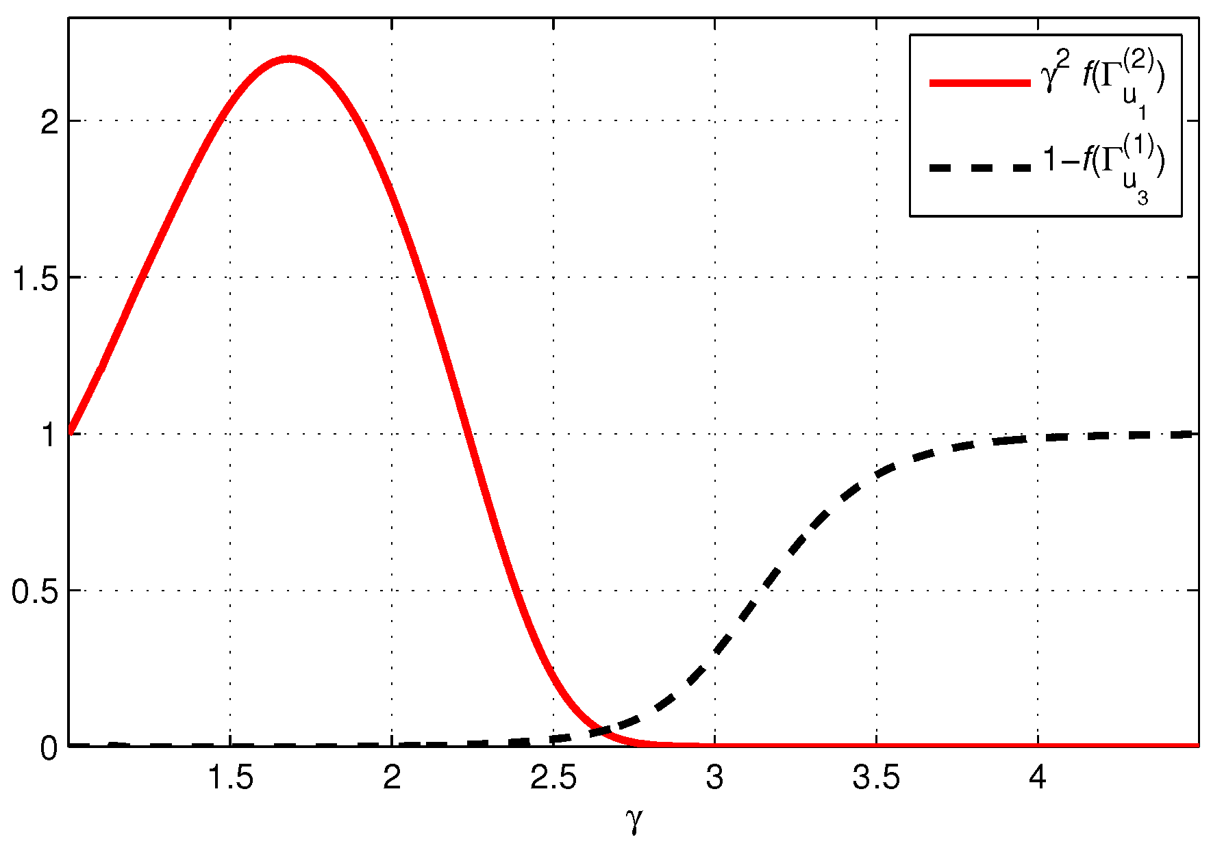
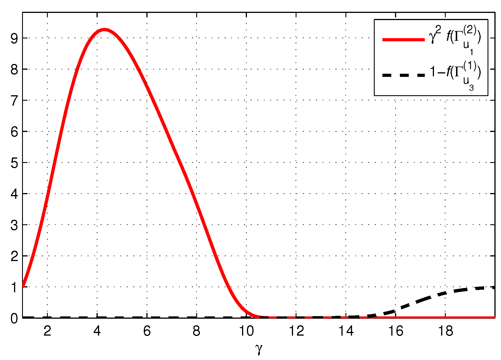
3.1. SINR Analysis for Power Control

From (7) and (9), we have
μ u , m = 1 K k = 1 K L u P u , m | Λ u , m ( k ) | 2 u U m ν u , m L u P u , m | Λ u , m ( k ) | 2 + σ N 2 .
Let S ( k ) and T ( k ) be respectively defined as
S ( k ) L u P u , m | Λ u , m ( k ) | 2 , T ( k ) u U m ν u , m L u P u , m | Λ u , m ( k ) | 2 + σ N 2 .
For analytical tractability, we consider the following approximation:
μ u , m = 1 K k = 1 K S ( k ) T ( k ) 1 K k = 1 K S ( k ) 1 K k = 1 K T ( k ) ,
where the approximation error decreases if the difference among the values of S ( k ) , k = 1 , , K , and the difference among the values of T ( k ) , k = 1 , , K , decrease. As the frequency correlation among the subcarriers in each chunk increases with the decrease in K, the approximation error of (25) decreases as K decreases. To validate the accuracy of this approximation, the root-mean-square errors (RMSEs) are depicted in Section 4 for moderate values of K; the RMSEs are generally small and decrease with a decrease in K.
For simplicity, let am [ A ] denote the arithmetic mean of A ( j ) , j = 1 , , K , such that
am [ A ] 1 K j = 1 K A ( j ) .
Then,
am [ S ] = L u P u , m · am [ | Λ u , m | 2 ] ,
am [ T ] = u U m ν u , m L u P u , m · am [ | Λ u , m | 2 ] + σ N 2 .
Owing to the QoS constraint, which corresponds to a BER less than 10 3 , the signal power of each user should be considerably larger than the noise power σ N 2 when it is supposed to be detected. Thus, it is expected that
L u P u , m · am [ | Λ u , m | 2 ] σ N 2 > Γ t h 1 ,
for each user u at chunk m. That is, the noise power σ N 2 is relatively negligible during the IMD. Thus, from (25), (27), and (28), we have
μ u , m am [ S ] am [ T ] = L u P u , m · am [ | Λ u , m | 2 ] u U m ν u , m L u P u , m · am [ | Λ u , m | 2 ] + σ N 2 L u P u , m · am [ | Λ u , m | 2 ] u U m ν u , m L u P u , m · am [ | Λ u , m | 2 ] = ζ u , m u U m ν u , m ζ u , m ,
where ζ u , m L u P u , m · am [ | Λ u , m | 2 ] . Substituting (30) into (16) yields
Γ u , m ( i + 1 ) = μ u , m 1 ν u , m ( i ) · μ u , m ζ u , m u U m ν u , m ( i ) ζ u , m 1 ν u , m ( i ) ζ u , m u U m ν u , m ( i ) ζ u , m = ζ u , m u U m , u u ν u , m ( i ) ζ u , m .
Hereafter, we use this SINR approximation to propose a power control method.
We define u k as the user who has the kth largest ζ u , m in U m . At the first iteration ( i = 1 ) of the IMD, the signal of u 1 is detected first as u 1 is expected to have the largest SINR. Subsequent values of SINR during the IMD are analyzed using SNR-variance density evolution (Section II-B). To start the density evolution at i = 1 , the initial values of variances ν u , m ( 0 ) are set to the maximum value 1; the variance decreases as the iteration proceeds because properly detected signals are successively canceled out by the iterative detector. Hence, from (31), the SINR of u 1 at i = 1 is given by
Γ u 1 , m ( 1 ) = ζ u 1 , m u U m , u u 1 ν u , m ( 0 ) ζ u , m
= ζ u 1 , m k = 2 U m ζ u k , m .
The SINRs of users u 2 and u 3 at i = 1 are sequentially expressed as
Γ u 2 , m ( 1 ) = ζ u 2 , m f ( Γ u 1 , m ( 1 ) ) ζ u 1 , m + k = 3 U m ζ u k , m
Γ u 3 , m ( 1 ) = ζ u 3 , m f ( Γ u 1 , m ( 1 ) ) ζ u 1 , m + f ( Γ u 2 , m ( 1 ) ) ζ u 2 , m + k = 4 U m ζ u k , m ,
where in (34), we have updated ν u 1 , m ( 0 ) to ν u 1 , m ( 1 ) and, in (35), we have updated ν u 1 , m ( 0 ) and ν u 2 , m ( 0 ) to ν u 1 , m ( 1 ) and ν u 2 , m ( 1 ) , respectively, by using (17) with the corresponding SINR values at i = 1 .
During SNR-variance density evolution, the variance ν u 1 , m = f Γ u 1 , m decreases exponentially as the SINR Γ u 1 , m increases (Figure 3); hence, if the SINR of u 1 is sufficiently large for reliable detection, the interference caused by u 1 is considerably reduced during the detection of the signals of other users. The simple idea of the proposed power control scheme is that the interference from the signal of user u 1 should be successfully canceled out before the detection of the signal of user u 2 at the second iteration, i = 2 . Generally, the signal of u j for all j k should be sequentially canceled out before the detection of the signal of u k + 1 at i = k + 1 . To achieve this, the proposed method will properly control the signal power of each user. To derive a specific condition, we examine the MAI caused by u 1 toward u 2 at i = 2 .
By proceeding with density evolution, the SINR of user u 2 at i = 2 is given by
Γ u 2 , m ( 2 ) = ζ u 2 , m f Γ u 1 , m ( 2 ) ζ u 1 , m + k = 3 U m f Γ u k , m ( 1 ) ζ u k , m .
The denominators of (34) and (36) represent the MAIs for the detection of u 2 at the first and second iterations, respectively. We denote the MAI for the detection of u k at the ith iteration as MAI u k , m ( i ) . Then, we have
MAI u 2 , m ( 0 ) = ζ u 1 , m + k = 3 U m ζ u k , m
MAI u 2 , m ( 1 ) = f Γ u 1 , m ( 1 ) ζ u 1 , m + k = 3 U m ζ u k , m
MAI u 2 , m ( 2 ) = f Γ u 1 , m ( 2 ) ζ u 1 , m + k = 3 U m f Γ u k , m ( 1 ) ζ u k , m ,
and the MAI decreases as the IMD proceeds as follows:
MAI u 2 , m ( 0 ) > MAI u 2 , m ( 1 ) > MAI u 2 , m ( 2 ) .
If we assume that the interference from the signal of u 1 is fully canceled out at i = 2 , then the decrease in MAI caused by twice-iterated IMD should be larger than the signal power ζ u 1 , m , as it is canceled out from the detection. Thus, we determine the following criterion for efficient power control:
MAI u 2 , m ( 0 ) MAI u 2 , m ( 2 ) > ζ u 1 , m .
This inequality can be considered to be a condition for the successful signal detection of u 1 before the signal detection of u 2 at the second iteration.
The inequality (41) can be rewritten by using (37) and (39) as follows:
MAI u 2 , m ( 0 ) MAI u 2 , m ( 2 ) = ζ u 1 , m + k = 3 U m ζ u k , m f Γ u 1 , m ( 2 ) ζ u 1 , m k = 3 U m f Γ u k , m ( 1 ) ζ u k , m = 1 f Γ u 1 , m ( 2 ) ζ u 1 , m + k = 3 U m 1 f Γ u k , m ( 1 ) ζ u k , m > ζ u 1 , m ,
and, from the second equality, we have
k = 3 U m 1 f Γ u k , m ( 1 ) ζ u k , m > f Γ u 1 , m ( 2 ) ζ u 1 , m .
This inequality indicates that the remaining interference from u 1 at i = 2 should be smaller than the sum of canceled interferences from users u 3 , , u U m at i = 1 . As we are focusing on the detection of u 1 at the first iteration, we assume that the signals of users u 4 , , u U m are barely detected at this iteration. This is a reasonable assumption as the remaining interferences from users u 1 , u 2 , and u 3 are still large at this stage. Specifically, we assume that
f Γ u , m ( 1 ) = ν u , m ( 1 ) 1 , u { u 4 , , u U m } .
Then, (43) can be simplified to
1 f Γ u 3 , m ( 1 ) ζ u 3 , m f Γ u 1 , m ( 2 ) ζ u 1 , m .
Please note that this condition is derived initially from our main criterion (41) for efficient power control.
Now, we consider the case of k 2 . By generalizing the criterion in (41), we consider the condition for the successful signal detections for users u 1 , , u k (such that their signals were successfully canceled out) before the signal detection of u k + 1 at the ( k + 1 ) th iteration.
In mathematical terms, it can be written as
MAI u k + 1 , m ( 0 ) MAI u k + 1 , m ( k + 1 ) > j = 1 k ζ u j , m .
That is, the decrease in MAI caused by k-times-iterated IMD should be larger than the total power of the signals of users, u 1 , , u k , as they were successfully canceled out before the signal detection of u k + 1 at i = k + 1 . Then, using formulas (41) to (45) as a basis condition and inductively assuming that the signals of u 1 , , u k were successfully canceled out before i = k + 1 , a strong mathematical induction can be applied to obtain the following inequality from (46):
( 1 f ( Γ u k + 2 , m ( k ) ) ) ζ u k + 2 , m f ( Γ u k , m ( k + 1 ) ) ζ u k , m .
Thus, (47) also indicates the successful detection of the signals of users u 1 , , u k before the detection of u k + 1 at i = k + 1 , and we intend to propose a power control algorithm that achieves this condition for all k = 1 , , U m 2 . If (47) is consecutively satisfied for all k = 1 , , U m 2 , then the following detection of the last user, at the subsequent iteration, will be interference-free; as (47) is the condition for the detection of the ( k + 1 ) th user, the case k = U m 1 corresponds to the detection of the last user.
The inequality in (47) can be rewritten as
ζ u k + 2 , m ζ u k , m f ( Γ u k , m ( k + 1 ) ) 1 f ( Γ u k + 2 , m ( k ) ) .
From (48), the following observations can be made:
  • If f ( Γ u k , m ( k + 1 ) ) 1 f ( Γ u k + 2 , m ( k ) ) C , k = 1 , , U m 2 , for some constant C, then imposing a geometric sequence for the values of ζ u k , m (e.g., ζ u k + 1 , m = C ζ u k , m ) is sufficient to ensure (48) for all k = 1 , , U m 2 .
  • Suppose it is possible to conversely prove the statement: there always exists a constant C for which f ( Γ u k , m ( k + 1 ) ) 1 f ( Γ u k + 2 , m ( k ) ) C is true for all k = 1 , , U m 2 , as long as ζ u k , m is a geometric sequence with respect to k. Then, from the first observation, we can argue that there exists a geometric sequence with an appropriate common ratio (possibly C ) that guarantees our criterion for the power control given in (47) or (48).
Based on these observations, we verify the value of f ( Γ u k , m ( k + 1 ) ) 1 f ( Γ u k + 2 , m ( k ) ) when ζ u k , m takes the kth value of a geometric sequence { a k : k = 1 , U m } , which is defined as
a k + 1 = a k γ ,
where 1 γ is the common ratio. Each term of the sequence can be calculated as
a k = a U m · γ U m k , k = 1 , , U m .
With ζ u k , m = a k , we have
Γ u k , m ( k + 1 ) = ζ u k , m j = 1 k 1 f ( Γ u j , m ( k + 1 ) ) ζ u j , m + j = k + 1 U m ζ u j , m ( a ) ζ u k , m j = 1 k 1 ζ u j , m + j = k + 1 U m ζ u j , m min k = 1 , , U m ζ u j , m j = 1 U m ζ u j , m ( b ) ζ u U m , m U m · ζ u 1 , m = ( c ) 1 U m · γ U m 1 ,
for all k = 1 , , U m 2 , where (a) follows because f ( x ) < 1 , x > 0 (Figure 3), (b) follows because u 1 and u U m are the users with the largest and smallest ζ u , m , respectively, and (c) follows from (50). Similarly, Γ u k + 2 , m ( k ) also satisfies
Γ u k + 2 , m ( k ) = ζ u k + 2 , m j = 1 k + 1 f ( Γ u j , m ( k ) ) ζ u j , m + j = k + 3 U m ζ u j , m min k = 1 , , U m ζ u j , m j = 1 U m ζ u j , m 1 U m · γ U m 1 ,
for all k = 1 , , U m 2 . As f ( x ) is a decreasing function (Figure 3), (51) and (52) indicate that
f ( Γ u k , m ( k + 1 ) ) 1 f ( Γ u k + 2 , m ( k ) ) f ( U m 1 · γ 1 U m ) 1 f ( U m 1 · γ 1 U m ) ,
for all k = 1 , , U m 2 . With (53) and the observations made after (48), we can prove the existence of a geometric sequence a k that guarantees (48) with ζ u k , m = a k , for all k = 1 , , U m 2 . In this context, we propose a power control method that uses a geometric sequence as defined in (50). Furthermore, the value of a U m is chosen as a U m = σ N 2 · Γ t h to satisfy the QoS constraint in (22). As f ( x ) does not have an explicit form, an appropriate value of γ that makes (48) true will be obtained using a numerical estimation with a lookup table for f ( · ) . We first describe the entire process of the proposed algorithm.

3.2. Proposed Power Control Algorithm

The basic strategy of the proposed power control algorithm is to make the signal powers of the users in chunk m satisfy the relation of the geometric sequence. That is, the algorithm checks the inequality ζ u k , m a U m · γ U m k for each user u k in the decreasing order of k. If ζ u k , m a U m · γ U m k , it decreases the signal power ζ u k , m as
ζ u k , m = a U m · γ U m k .
Conversely, if ζ u k , m < a U m · γ U m k , the proposed method considers that u k is not suitable to be successfully detected at chunk m, and hence, the algorithm excludes u k from the user set U m of chunk m. That is, if ζ u k , m < a U m · γ U m k , update U m and U m to U m { u k } and U m 1 , respectively.
Step 1. Initialization
Initialize the subcarrier chunk index: m = 1 .
Initialize two indices: n = U m and k = U m .
Set P u , m = 1 , u , and U m = { u | ζ u , m Γ t h σ N 2 } .
Step 2. Power control
  • Define p = Γ t h σ N 2 · γ U m n L u k · am [ | Λ u k , m | 2 ] .
    If P u k , m p , set P u k , m = p and update n n 1
    else update user set: U m U m { u k }
  • If k > 1 , update k k 1 and go to Step 2-1)
    else go to Step 3.
Step 3. User scheduling
Perform the pattern-aware user scheduling in [23] by considering U m as the input (initial) set.
Step 4. Decision of termination
If m < M , set m m + 1 and go to Step 2. Otherwise, terminate the algorithm.

3.3. Appropriate Value of γ

The performance of the proposed power control strategy depends on the value of the common ratio γ because it determines whether our power control criterion (47) is satisfied. With ζ u k , m = a k , the inequality (47) can be rewritten as
1 f Γ u 3 , m ( 1 ) ζ u 3 , m f Γ u 1 , m ( 2 ) ζ u 1 , m
1 f Γ u 3 , m ( 1 ) a U m · γ U m 3 f Γ u 1 , m ( 2 ) a U m · γ U m 1
1 f Γ u 3 , m ( 1 ) f Γ u 1 , m ( 2 ) γ 2 ,
where we consider the case of k = 1 for the estimation of γ because the best condition for the first iteration can reduce the error propagation in the following detections. We can reduce the transmit power by making the value of γ as small as possible; this corresponds to accommodating more users in the same chunk, which further corresponds to an increased spectral efficiency (22). Thus, the proposed method selects the smallest value of γ that satisfies the inequality at the right-hand side (RHS) of (56). As Γ u 3 , m ( 1 ) is also given by a function of γ , and as f is a numerically estimated function in SNR-variance density evolution, the inequality in (56) cannot be explicitly solved with respect to γ . Thus, the minimum value of γ , which is denoted as γ s o l , is obtained through a simple numerical quantization in this study. Figure 4 and Figure 5 illustrate the procedure by depicting the behaviors of 1 f ( Γ u 3 , m ( 1 ) ) and f ( Γ u 1 , m ( 2 ) ) γ 2 as functions of γ . Both 1 f ( Γ u 3 , m ( 1 ) ) and f ( Γ u 1 , m ( 2 ) ) γ 2 are nonlinear functions of γ ; 1 f ( Γ u 3 , m ( 1 ) ) peaks at a relatively low γ whereas f ( Γ u 1 , m ( 2 ) ) γ 2 increases to an asymptote at 1 as γ increases. Thus, simple numerical quantization can determine the minimum solution of the inequality at the RHS of (56); we only require a lookup table for the function f ( · ) in SNR-variance density evolution to determine γ s o l offline. Table 2 summarizes the values of γ s o l , which vary depending on the MCS. The pre-calculated γ s o l is substituted into the proposed algorithm to increase the spectral efficiency and reduce the total transmit power in each chunk.

4. Simulation Results and Discussion

In [7], it was demonstrated that SC-GFDMA generally outperforms the conventional SC-FDMA in terms of spectral efficiency. Thus, in this section, we demonstrate that the spectral efficiency achieved by SC-GFDMA can be further increased by using the proposed power control algorithm. The near-optimal pattern-aware scheduling algorithm proposed in [23] is applied for all the methods considered in this section for a fair comparison. Consequently, the simulation results obtained without power control in this section corresponds to the results obtained using the pattern-aware scheduling algorithm in [23] after allocating equal powers to users in the same chunk. To the best of our knowledge, [7] is the only study that considered unequal power allocation to different users in the same chunk, although a specific power allocation strategy was not proposed in [7]. Thus, the effectiveness of the proposed method is verified by comparing it with the work in [23] (corresponds to the case without power control in this section) and the work in [7] (which is the best existing SC-GFDMA scheme).

4.1. Simulation Setup

In simulations, we consider an uplink SC-GFDMA system, described in Section II, with a bandwidth of 5-MHz and 512 subcarriers. The center frequency is 2 GHz. Unless otherwise specified, the number of total users is 8, and the distances between the BS and the users are set to deterministic values: {1, 8/7, 9/7, 10/7, 11/7, 12/7, 13/7, 2} m, having the same intervals. The 512 subcarriers are grouped into M = 16 chunks each of which consists of K = 32 consecutive subcarriers. Perfect uplink channel estimation is assumed at the BS. A convolutional code with a constraint length of 3 is considered. For the QoS constraint, Γ t h is set to the value that corresponds to the target BER of 10 5 . The channels between the BS and the users are frequency-selective fading channels. We assume that each channel is a six-tap typical urban channel [29] and that the normalized Doppler frequency is 0.001. The maximum number of iterations of SNR-variance density evolution is 20. The iteration is stopped when the sum of SINRs for all the users stops increasing. Unless otherwise specified, the values from Table 2 are used for the proposed algorithm.
First, we verify the approximation of μ u , m in (25), which is expected to be close when K is small. When the proposed power control scheme is applied, the RMSEs of approximating μ u 1 , m by using am [ S ] am [ T ] , at i = 1 , are depicted in Figure 6. The RMSEs are generally small and can be reduced by choosing a small chunk size as expected.

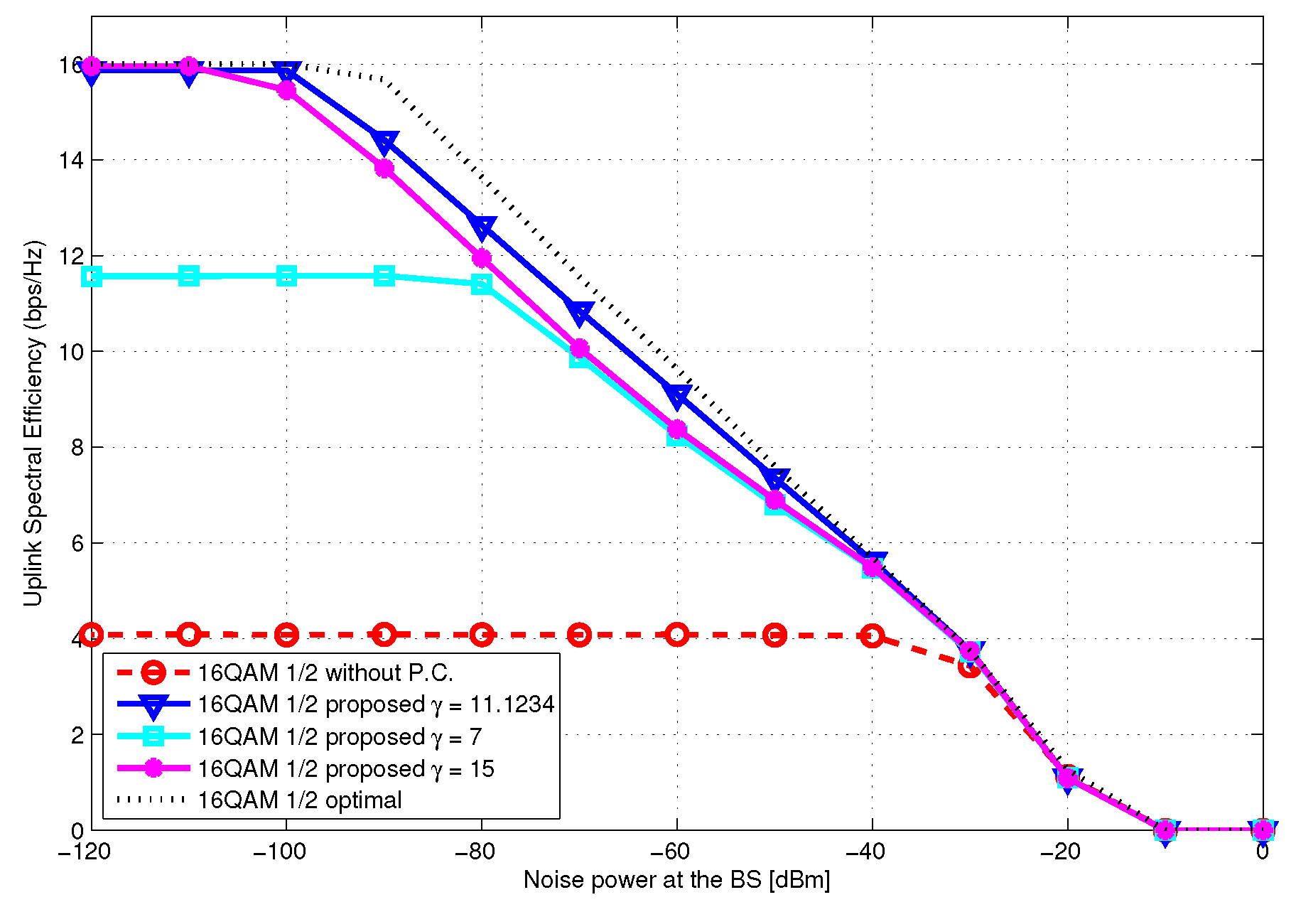
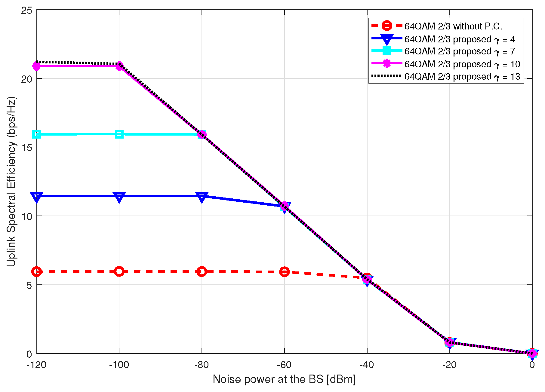
4.2. Spectral Efficiency Enhancement

The previously proposed power control method for SC-GFDMA [7] achieves 7% higher spectral efficiency than that achieved by the conventional SC-GFDMA without power control (Figure 7) at σ N 2 = 10 dBm. However, it is still considerably lower than the spectral efficiency achieved with the optimal transmit powers of the users determined based on an exhaustive method; this exhaustive method is only possible in simulations and is infeasible to implement in practical systems. In contrast, the proposed power control method provides near-optimal spectral efficiency. In simulations for Figure 7, the number of total users is fixed to 5 and pathloss is not applied to compare the proposed algorithm with the method proposed in [7].
The spectral efficiencies achieved by the proposed power control scheme are close to those achieved using exhaustively chosen optimal power allocations (Figure 8 and Figure 9), regardless of the MCS. The spectral efficiencies of the proposed scheme are considerably higher than that of the conventional scheme without power control ( P u , m = 1 ). The maximum spectral efficiency with QPSK-3/4 is 12; the proposed scheme achieves the maximum at σ N 2 < 50 dBm (Figure 8). The spectral efficiencies of the proposed scheme with 16QAM-1/2 become saturated at 15.87 when σ N 2 < 100 dBm (99.2% of the maximum spectral efficiency of 16 is achieved) (Figure 9). That is, the proposed algorithm can exploit the benefits of high-order MCS efficiently; furthermore, it consumes less power than the conventional method without power control.
In Figure 10 and Figure 11, the spectral efficiencies obtained using the proposed power control algorithm are simulated with multiple values of γ including γ = γ s o l . When γ γ s o l , the criterion (47) is not satisfied (see Figure 4 and Figure 5); hence, the spectral efficiency is relatively low and becomes saturated when the noise power is relatively low. That is, the remaining interference from u k can affect the signal detection of other users at i k + 2 , for some k, and can thus degrade the spectral efficiency. When γ γ s o l , the maximum spectral efficiency is achieved, because (47) is still satisfied (Figure 4 and Figure 5), but it is slightly lower at some noise power level, compared with the case using γ = γ s o l ; moreover, the use of γ larger than γ s o l results in the consumption of more transmit power. In both figures, the proposed power control algorithm increases the spectral efficiency regardless of the specific value of γ . These results demonstrate the robustness of the proposed power control criterion analyzed in the previous section and also the importance of using an appropriate power control algorithm in the SC-GFDMA structure.
Figure 12 depicts the spectral efficiency obtained using 64QAM with 2/3 code rate, which demonstrates that the proposed power control also provides significant gain for high-order modulations. As seen in Figure 10 and Figure 11, spectral efficiency increases as γ increases, and the amount of increase saturates as γ approaches the optimal value. Because the maximum spectral efficiency available by using MCS 64QAM-2/3 with 8 users is 32 = 4 × 8 , the proposed method achieves 68.7 % of the maximum value, where the maximum is achieved only when all 8 users perfectly share each chunk, with the BER being less than the threshold. That is, the proposed method can schedule approximately 5.5 users on average in each chunk. This implies that the average number of users that can share each chunk while satisfying the QoS constraint decreases as the MCS level increases. However, the total spectral efficiency is still increased by using 64QAM when compared with 16QAM.

4.3. Transmit Power Saving

Without power control, each user transmits a signal with its own maximum power. The spectral efficiency of this conventional scheme is low despite its high power consumption. The proposed power control scheme reduces the transmit power of each user according to the power control criterion so that the total transmit power of the proposed scheme is considerably lower than that of the conventional scheme without power control. The consumption of transmit power per user is simulated in Figure 13 and Figure 14. The conventional scheme without power control uses a constant transmit power. In contrast, the transmit power of the proposed scheme decreases as the noise power at the BS decreases. Even with a reduced transmit power, the proposed method outperforms the conventional methods as shown in the previous figures (Figure 7, Figure 8, Figure 9, Figure 10 and Figure 11).

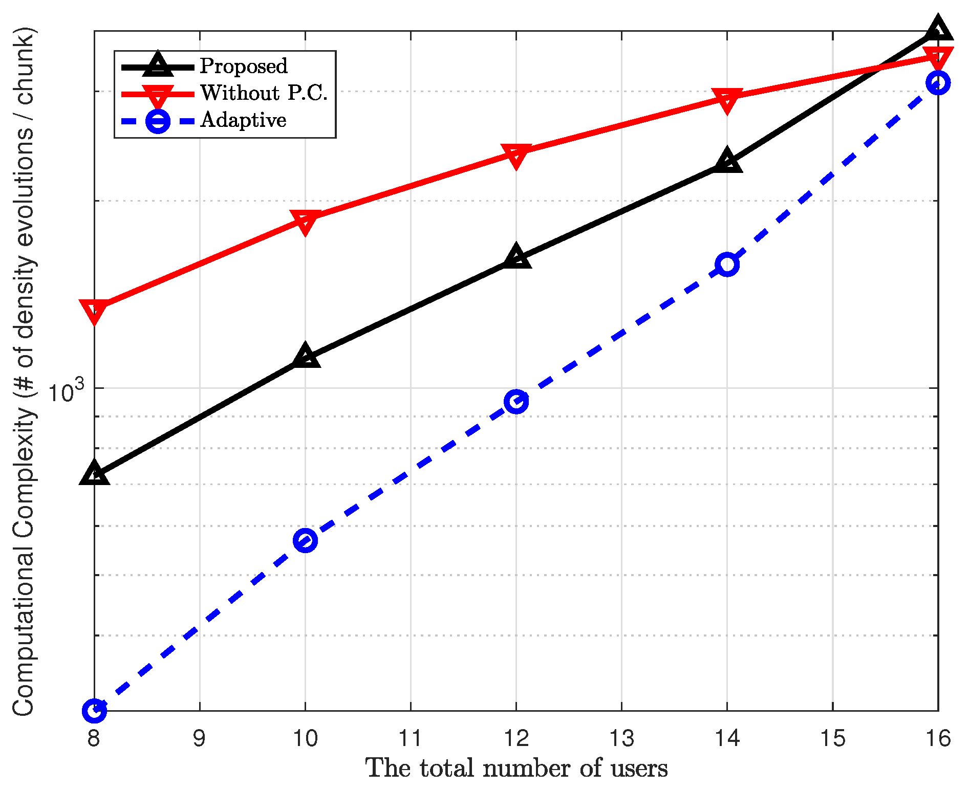
4.4. Computational Complexity

The SC-GFDMA uses iterative detection to decouple signals from multiple users sharing the same chunk. This iterative approach requires additional computations to achieve a higher spectral efficiency. Thus, as discussed in Section 1, a commercial network operator should consider a trade-off between the additional complexity and the increase in spectral efficiency. In this section, to support such a decision, we provide some quantitative results on the computation complexity.
As a measure of the computational complexity, we use the number of performing SNR-variance density evolutions per chunk during iterative detection. The primary purpose of the proposed method is to secure as many users as possible by properly adjusting the transmit powers of users. In this aspect, the proposed method may require more computations to secure more users. On the other hand, as discussed in Section 2.3 (Figure 2), the proposed power control method functions as a pre-scheduler by excluding inappropriate users before the scheduling. Since the number of candidates for scheduling is (appropriately) decreased, we can say that the proposed method also has an aspect that corresponds to the reduction in computational complexity. In summary, the proposed method does not always require more computational complexity than the conventional method without power control, and it depends on the systems parameters such as the number of users, SNR, the number of iterations, and the channel coefficients.
Figure 15 compares the computation complexity simulated with and without the proposed power control. The proposed method generally had lower complexity than the conventional method without power control, except when U = 16 . For both cases, the computation complexity depends on the number of iterations for the IMD. As the number of iterations decreases, both the computational complexity and the available spectral efficiency decrease with high probability. Thus, a network operator should find an appropriate number of iterations for commercial services. However, it is extremely difficult to explicitly find an optimal number as it depends on various system parameters. Instead, one may consider an algorithm that adaptively terminates the IMD at a certain point if no significant improvement is expected, such that the proposed method can reduce the computational complexity without much loss in the available spectral efficiency. For example, at each iteration i, we may check the following criterion:
k Γ u k , m ( i ) k Γ u k , m ( i 1 ) < κ ,
with a threshold κ . The difference k Γ u k , m ( i ) k Γ u k , m ( i 1 ) measures the amount of increase in SINR between consecutive iterations. Thus, if this difference is very small, we may consider that no significant improvement will be expected in remaining iterations. In this context, the proposed method terminates the IMD if this inequality is satisfied. This type of adaptive algorithm, with an appropriate value of κ , can further decrease the complexity of the proposed scheme as demonstrated in Figure 15 (the dashed line with circle marker is the complexity obtained by applying this adaptive algorithm, with κ = 0.01 , to the proposed method).

5. Conclusions

This paper presented a power control algorithm for an uplink SC-GFDMA system. We formulated and simplified the maximization problem of spectral efficiency and used a simple approximation to determine a power control criterion that exploits the non-orthogonal characteristic of the SC-GFDMA structure. The specific criterion was derived from the SINR analysis performed based on SNR-variance density evolution. The spectral efficiency was considerably improved by limiting the signal power of each user according to the proposed criterion. In simulations, the proposed algorithm provided significantly higher spectral efficiency than the conventional methods, even with a considerably reduced total transmit power.

Future Work

In this study, to emphasize the notable impact of power control, we considered a relatively simple system using the SC-GFDMA structure. Thus, a further study on power control may consider a more complicated SC-GFDMA system involving hybrid subcarrier mapping and different MCSs for different users in the same chunk. As the power control algorithm is derived independent of user scheduling in this study, one may also consider a joint power control and scheduling scheme. In addition, as the proposed method was derived by tracking the SINR performance of the IMD, one may attempt to find further applications of the proposed method for any system using an iterative detection, even if the system does not use the SC-GFDMA structure.
Using the SC-GFDMA structure, with the proposed power control, the available spectral efficiency in each chunk can be significantly increased compared with that available in the typical SC-FDMA. As each chunk is used as a unit for resource allocation in practical systems [8,9], the proposed system can be regarded as an alternative to SC-FDMA while having resource grids with improved potential performance. Thus, the system-level resource allocation and management techniques, which are applied across subcarriers, can be further studied based on the analysis framework derived in this paper to improve the system-level performance in the network.

Author Contributions

Conceptualization, Y.-S.C.; Data curation, Y.-S.C.; Formal analysis, M.M.; Funding acquisition, M.M.; Methodology, Y.-S.C.; Software, Y.-S.C.; Supervision, M.M.; Validation, Y.-S.K.; Visualization, Y.-S.K.; Writing—original draft, Y.-S.C. and M.M.; Writing—review & editing, M.M. All authors have read and agreed to the published version of the manuscript.

Funding

This work was supported by the National Research Foundation of Korea (NRF) grant funded by the Korea government (MSIT) (No. 2017R1C1B5074268).

Conflicts of Interest

The authors declare no conflict of interest.

References

  1. Pancaldi, F.; Vitetta, G.M.; Al-Dhahir, N.; Uysal, M.; Muhaidat, S.; Kalbasi, R. Single-Carrier Frequency Domain Equalization: A Review. IEEE Signal Process. Mag. 2008, 25, 37–56. [Google Scholar] [CrossRef]
  2. Ekstrom, H.; Furuskar, A.; Karlsson, J.; Meyer, M.; Parkvall, S.; Torsner, J.; Wahlqvist, M. Technical solutions for the 3G long-term evolution. IEEE Commun. Mag. 2006, 44, 38–45. [Google Scholar] [CrossRef]
  3. Falconer, D.; Ariyavisitakul, S.; Benyamin-Seeyar, A.; Eidson, B. Frequency Domain Equalization for Single-carrier Broadband Wireless Systems. IEEE Commun. Mag. 2002, 40, 58–66. [Google Scholar] [CrossRef] [Green Version]
  4. Myung, H.G.; Lim, J.; Goodman, D.J. Single Carrier FDMA for Uplink Wireless Transmission. IEEE Veh. Technol. Mag. 2006, 3, 30–38. [Google Scholar] [CrossRef]
  5. Yune, T.W.; Choi, C.H.; Im, G.H.; Lim, J.B.; Kim, E.S.; Cheong, Y.C.; Kim, K.H. SC-FDMA with iterative multiuser detection: improvements on power/spectral efficiency. IEEE Commun. Mag. 2010, 48, 164–171. [Google Scholar] [CrossRef]
  6. Lim, J.B.; Choi, C.H.; Yune, T.W.; Im, G.H. Iterative multiuser detection for single-carrier modulation with frequency-domain equalization. IEEE Commun. Lett. 2007, 11, 471–473. [Google Scholar] [CrossRef]
  7. Choi, C.H.; Lim, H.J.; Kim, T.K.; Im, G.H.; Lawrence, V.B. Spectral efficient multiuser technique with channel-dependent resource allocation schemes. IEEE Trans. Wirel. Commun. 2012, 11, 990–999. [Google Scholar] [CrossRef]
  8. 3GPP Technical Specification Group Radio Access Network; Evolved Universal Terrestrial Radio Access (E-UTRA). Physical Channels and Modulation (Release 15); 3GPP TS 36.211 V15.4.0; 3GPP: Paris, France, 2018; Available online: http://www.3gpp.org (accessed on 18 December 2019).
  9. 3GPP Technical Specification Group Radio Access Network; Evolved Universal Terrestrial Radio Access (E-UTRA). Physical Layer Procedures (Release 15); 3GPP TS 36.213 V15.4.0; 3GPP: Paris, France, 2018; Available online: http://www.3gpp.org (accessed on 18 December 2019).
  10. Khamidehi, B.; Sabbaghian, M. Resource Allocation for SC-FDMA Femtocell Networks. IEEE Trans. Veh. Technol. 2019, 68, 4573–4585. [Google Scholar] [CrossRef]
  11. Ali, S.; Ahmad, A.; Iqbal, R.; Saleem, S.; Umer, T. Joint RRH-Association, Sub-Channel Assignment and Power Allocation in Multi-Tier 5G C-Rans. IEEE Access 2018, 6, 34393–34402. [Google Scholar] [CrossRef]
  12. Ng, B.K.; Choi, T.; Lam, C.T. Performance of SC-FDMA-based multiuser massive MIMO system in the presence of phase noise. In Proceedings of the 2017 IEEE 17th International Conference on Communication Technology (ICCT), Chengdu, China, 27–30 October 2017. [Google Scholar]
  13. Lu, X.; Ni, Q.; Zhao, D.; Cheng, W.; Zhang, H. Resource virtualization for customized delay- bounded QoS provisioning in uplink VMIMO-SC-FDMA systems. IEEE Trans. Commun. 2019, 67, 2951–2967. [Google Scholar] [CrossRef]
  14. Lu, X.; Yang, K.; Fan, N.; Guo, H.; Zhang, H. Joint clustering of users and resources for multi-cell VMIMO-SC-FDMA uplink systems. IEEE Trans. Veh. Technol. 2019, 68, 1417–1430. [Google Scholar] [CrossRef]
  15. Hu, Y.; Wang, F.; Lu, J. Low PAPR Filter Bank Single Carrier for 5G mMTC. IEEE Internet Things J. 2019, 6, 6887–6895. [Google Scholar] [CrossRef]
  16. Ghavimi, F.; Lu, Y.W.; Chen, H.H. Uplink scheduling and power allocation for M2M communications in SC-FDMA-based LTE-A networks with QoS guarantees. IEEE Trans. Veh. Technol. 2017, 66, 6160–6170. [Google Scholar] [CrossRef]
  17. Bao, P.; Guan, Q.; Guan, M. A multiuser detection algorithm in the uplink SC-FDMA system for green communication network. IEEE Access 2019, 4, 5982–5989. [Google Scholar] [CrossRef]
  18. Kaligineedi, P.; Bhargava, V.K. Frequency-domain turbo equalization and multiuser detection for DS-UWB systems. IEEE Trans. Wirel. Commun. 2008, 7, 3280–3284. [Google Scholar] [CrossRef]
  19. Lunttila, T.; Lindholm, J.; Pajukoski, K.; Tiirola, E.; Toskala, A. EUTRAN uplink performance. In Proceedings of the 2007 2nd International Symposium on Wireless Pervasive Computing, San Juan, Puerto Rico, 5–7 February 2007. [Google Scholar]
  20. Wong, I.C.; Oteri, O.; McCoy, W. Optimal resource allocation in uplink SC-FDMA systems. IEEE Trans. Wirel. Commun. 2009, 8, 2161–2165. [Google Scholar] [CrossRef]
  21. Triantafyllopoulou, D.; Kollias, K.; Moessner, K. QoS and energy efficient resource allocation in uplink SC-FDMA systems. IEEE Trans. Wirel. Commun. 2015, 14, 3033–3045. [Google Scholar] [CrossRef] [Green Version]
  22. Zhang, X.; Shen, X.; Xie, L. Uplink achievable rate and power allocation in cooperative LTE-advanced networks. IEEE Trans. Veh. Technol. 2016, 65, 2196–2207. [Google Scholar] [CrossRef]
  23. Cho, Y.S.; Kim, D.; Kim, T.K.; Im, G.H. Improved channel-dependent user selection for an SC-FDMA system. IEEE Commun. Lett. 2012, 16, 1608–1611. [Google Scholar]
  24. Shah, S.T.; Gu, J.; Hasan, S.F.; Chung, M.Y. SC-FDMA-Based resource allocation and power control scheme for D2D communication using LTE-A uplink resource. EURASIP J. Wirel. Commun. Netw. 2015, 137. [Google Scholar] [CrossRef] [Green Version]
  25. Ma, R.; Xia, N.; Chen, H.-H.; Chiu, C.-Y.; Yang, C.-S. Mode selection, radio resource allocation, and power coordination in D2D communications. IEEE Wirel. Commun. 2017, 24, 112–121. [Google Scholar] [CrossRef]
  26. Sesia, S.; Toufik, I.; Baker, M. LTE—The UMTS Long Term Evolution: From Theory to Practice, 2nd ed.; Wiley: Hoboken, NJ, USA, 2011. [Google Scholar]
  27. Divsalar, D.; Dolinar, S.; Pollara, F. Iterative turbo decoder analysis based on density evolution. IEEE J. Sel. Areas Commun. 2001, 19, 891–907. [Google Scholar] [CrossRef] [Green Version]
  28. Shi, Z.; Schlegel, C. Joint iterative decoding of serially concatenated error control coded CDMA. IEEE J. Sel. Areas Commun. 2001, 19, 1646–1653. [Google Scholar]
  29. Stüber, G.L. Principles of Mobile Communication; Kluwer Academic Publishers: Norwell, MA, USA, 2001. [Google Scholar]
Figure 1. Frequency domain description for each time slot in SC-FDMA (a) and SC-GFDMA (b) with localized subcarrier mapping ( M = 4 , U = 4 ).
Applsci 10 00119 g001
Figure 2. Control plane procedure for power control and scheduling.
Applsci 10 00119 g002
Figure 3. Frequency domain variance f ( S I N R ) versus SINR.
Applsci 10 00119 g003
Figure 4. 1 f Γ u 3 , m ( 1 ) and f Γ u 1 , m ( 2 ) γ 2 as functions of γ , for QPSK-1/2.
Applsci 10 00119 g004
Figure 5. 1 f Γ u 3 , m ( 1 ) and f Γ u 1 , m ( 2 ) γ 2 as functions of γ , for 16QAM-1/2.
Applsci 10 00119 g005
Figure 6. RMSE of μ u 1 , m at i = 1 , caused by the approximation (25).
Applsci 10 00119 g006
Figure 7. Spectral efficiencies for QPSK-1/2 versus noise power; U = 5 and L u = 1 , u .
Applsci 10 00119 g007
Figure 8. Spectral efficiency for QPSK-3/4 versus noise power.
Applsci 10 00119 g008
Figure 9. Spectral efficiency for 16QAM-1/2 versus noise power.
Applsci 10 00119 g009
Figure 10. Spectral efficiency for QPSK-1/2 versus noise power with different values of γ .
Applsci 10 00119 g010
Figure 11. Spectral efficiency for 16QAM-1/2 versus noise power with different values of γ .
Applsci 10 00119 g011
Figure 12. Spectral efficiency for 64QAM-2/3 versus noise power with different values of γ .
Applsci 10 00119 g012
Figure 13. Transmit power of QPSK-1/2 versus noise power.
Applsci 10 00119 g013
Figure 14. Transmit power of 16QAM-1/2 versus noise power.
Applsci 10 00119 g014
Figure 15. Computational complexity with and without power control; the number of iterations is 20.
Applsci 10 00119 g015
Table 1. List of primary symbols.
MTotal number of chunks in frequency domain
NTotal number of subcarriers in frequency domain
KNumber of subcarriers in each chunk
U Set of all users
UTotal number of users: U = | U |
U m Set of users allocated to chunk m
U m Number of users in chunk m: U m = | U m |
L u Pathloss from BS to user u
P u , m Transmit power of user u at chunk m
Λ u , m Channel frequency response of user u at chunk m
ν u , m Estimated variance of the signal of user u at chunk m
μ u , m Estimated mean of the signal of user u at chunk m
Γ u , m Estimated SINR of user u at chunk m
Γ t h Threshold of SINR for QoS constraint
η m Spectral efficiency at chunk m
r m Single-user data rate of user u at chunk m
ζ u , m ζ u , m L u P u , m · am [ | Λ u , m | 2 ]
Table 2. Estimated values of γ s o l for different MCSs.
MCS γ sol
BPSK 1/21.6467
QPSK 1/22.6499
QPSK 3/45.2155
16QAM 1/211.1234
16QAM 2/325.7521
16QAM 3/430.8445

