Article

Development of Biomass Gasification Technology with Fluidized-Bed Reactors for Enhancing Hydrogen Generation: Part I, Hydrodynamic Characterization of Dual Fluidized-Bed Gasifiers

1
Chemistry Division, Institute of Nuclear Energy Research, Taoyuan 32546, Taiwan
2
Department of Forestry, National Chung Hsing University, Taichung 40227, Taiwan
3
Department of Mechanical Engineering, National Chung Hsing University, Taichung 40227, Taiwan
*
Authors to whom correspondence should be addressed.
Appl. Sci. 2020, 10(1), 2; https://doi.org/10.3390/app10010002
Submission received: 5 October 2019 / Revised: 16 December 2019 / Accepted: 16 December 2019 / Published: 18 December 2019
(This article belongs to the Section Applied Physics General)

Abstract

:

Featured Application

Various means, including operational and constructional factors, for enhancing hydrogen generation from biomass gasification are investigated. Efforts have been devoted to the development of so-called “indirect gasification technology”, which features the advantage of producing nearly nitrogen-free syngas. Indirect gasification process exhibits potential for enhancing H2 generation.

Abstract

Various means for enhancing hydrogen content in the syngas from gasification of solid biomass in fluidized-bed reactors were investigated in this study. Steam or oxygen-rich gas can be supplied as gasification medium, to improve the syngas characteristics. Alternatively, a so-called “indirect gasification technology” realizes the thermo-chemical conversion processes in dual reactors, respectively, for combustion and gasification, where gaseous streams in between are separated while solid materials are circulated through. Hence, with air as oxidant for combustion this system features the advantage of producing nearly nitrogen-free syngas. Baseline experiments were firstly carried out to identify performance features; then, parametric studies were conducted and positive trends for enhancing hydrogen generation via biomass gasification were revealed. Moreover, hydrodynamic characteristics in dual reactors were comprehensively envisaged in the cold-flow models to facilitate subsequent investigation into thermo-chemical processes. The experimental results indicated that the circulation mass of the bed material driven by the operating air exceeded the design value, which gave a comfortable safety factor of the engineering design. In addition, the average pressure distribution measured by the cyclic operation of the system was similar to that of the published literature. Based on the experimental results of the cold model, the suggestions of the operating tests in the hot model were addressed. Further efforts will be pursued to establish databases for clean energy and carbon abatement technologies.

1. Introduction

Syngas is converted thermo-chemically from carbonaceous feedstock via gasification technology, from which the reaction products mainly consist of CO and H2 with some amounts of CO2, H2O, CH4, etc. Gasification processes provide flexible applications to multiple energy and resource demands from the industry, and feature lower pollutant emissions [1]. Chemical products and liquid fuel can be produced via clean syngas, while some carbon could be fixed in the chemical products or separated in the processes. Hence, lower CO2 emission is released to the atmosphere. For generating electricity, syngas could also be delivered to combined-cycle featuring higher system efficiency and lower pollutant emission, compared to the counterparts of conventional coal-fired units.
Biomass is commonly regarded as carbon-neutral feedstock, and can be utilized for low-carbon energy systems. Fluidized bed is one of the major platforms of biomass gasification. Gasification medium (e.g., air, steam, CO2, etc.) flows through bed materials and fluidizes the solid particles. Some advantages of implementing fluidized bed for gasification have been documented in the literature [2,3,4]. For example, the addition of ilmenite to the solid inventory improves the distribution of oxygen throughout the furnace, so that ilmenite is able to alternately take up and release oxygen in the combustor of a 12-MWth circulating fluidized-bed (CFB) boiler/gasifier system [5].
There are three kinds of fluidized-bed reactors, namely bubbling, circulating, and dual fluidized-bed (DFB) reactors, commonly applied in the gasification processes. Fluidized-bed gasifiers feature higher mass flow rates, flexible feedstock, and relatively lower tar and particulates in the syngas, compared to the counterparts from updraft fixed-bed gasifiers. With the cheapest gasification agent, air, nitrogen prevails inevitably as near half content in the produced gas. In turn, it results in lower heating values, with major applications for boilers and internal combustion engines to generate steam and electricity. Other agents, such as steam and oxygen-rich gas, could provide the syngas with a lower nitrogen content or near nitrogen-free condition, to increase the application options in chemical products, alternative fuel, and hydrogen generation. The associated penalty is the higher cost of gasification agent compared to that of air. In addition, CO2 could also be adopted, together with steam or oxygen, to promote the Boudouard reaction to enrich CO in the syngas. The tar content in the syngas is affected by various conditions, such as operating temperature, equivalent ratio, and steam. To remove the tar in the downstream after the gasification unit, typical gas clean-up processes or catalyst reactor could be implemented to meet the requirement from the application [6,7].
Furthermore, the staged gasification by burning char in a separate, indirectly heated chamber seems to be a suitable way to reach high char conversion and yield low concentration of heavy tar in the syngas [8]. “Indirect gasification” realizes the whole conversion processes in dual reactors, for combustion and gasification, respectively. Moreover, solid materials are circulated through the two reactors, while gaseous streams in between are separated from each other (Figure 1). Compared to conventional “direct” gasifiers, where combustion and gasification reactions take place inside the same vessel, the energy-consuming ASU (Air Separation Unit) would not be needed to eliminate the influence of nitrogen in the syngas; hence, such technology poses potential for higher system efficiency. In addition, with steam as gasification medium, a higher H2/CO ratio in the syngas can be achieved, which would be more favorable for producing synthetic natural gas (SNG). A comprehensive review on dual fluidized-bed (DFB) biomass gasifiers has been published in the literature [9], in which various configurations were described.
There have been extensive investigations of biomass gasification and fluidized-bed gasification in the literature; for example, a comprehensive review is available elsewhere recently [6]. Moreover, citation of some systems operated today is also illustrated in this work, e.g., Vienna University of Technology (VUT) and Güssing in Austria [10], ECN (Energy Research Centre of the Netherlands) in The Netherlands [11]), IHI (Ishikawajima-Harima Heavy Industries) Co. [12] and EBARA (Ebara Corporation is a publicly traded manufacturing company based in Tokyo, Japan) [13] in Japan, etc. According to the literature, H2 content in the syngas from DFB could be higher than 35%, in general [10], which is higher than the typical value of H2 content in the bubbling fluidized-bed (BFB) gasification system. Besides, biomass gasification with pure steam in a fluidized bed may generate syngas with 60 vol. % H2 (dry basis) with relatively low tar content. This concept is also suitable for bio-SNG production [14].
Alternatively, a conceptual design of a new compact fluidized-bed reactor combined with gasification and combustion processes was originally proposed by Kunii in 1980 [15]. Furthermore, the concept to develop the applications of the interconnected fluidized bed (IFB), such as the regenerative desulfurization process [16,17,18,19], has been realized at Delft University of Technology (DUT) in The Netherlands during the 1990s. A 200 kWth interconnected fluidized-bed gasification test facility was constructed at the Industrial Technology Research Institute (ITRI), Taiwan in 2004, which aimed to carry out gasification of refuse derived fuel (RDF) and to obtain the performance information for future development [20].
Both IFB and DFB exhibit key features of two independent reaction zones, between which the gases are isolated. It is easy to adopt steam as a gasification medium to generate nitrogen-free syngas. The scope of this work will be focused on the hydrodynamic characterization of dual fluidized-bed gasifiers in a cold flow model, in order to provide the guidance for testing the subsequent DFB hot model; whereas the investigation on the performance of DFB under hot condition, as well as study on IFB, will be documented elsewhere later.

2. Materials and Methods

As a start-up effort, a 30 kWth bubbling fluidized-bed (BFB) gasification system was commissioned at the Institute of Nuclear Energy Research (INER) in Taiwan; then, the facilities would be subsequently extended to the circulating fluidized-bed (CFB) mode. Furthermore, commissioning and testing efforts of various dual fluidized-bed reactors are in progress. This work acquired preliminary results for the gasification of eucalyptus, and further efforts will be pursued to establish databases for gasification reaction performance and optimal operating parameters.

2.1. Feedstock

There are two types of feedstock used in gasification, i.e., eucalyptus wood chips and mixed wood pellets. The feedstock size is smaller than 7 mm. Based on the ultimate analysis, eucalyptus wood chips showed the following weight-percent composition (daf: dry ash free): 49.07% C, 4.92% H, 44.94% O, 0.27% N, 0.16% S, etc.; while the counterpart of mixed wood pellets was 49.52% C, 6.26% H, 43.5% O, 0.72% N, and 0% S. By proximate analysis, the moisture, ash, and combustible were 11.48%, 0.56%, and 85.9% in eucalyptus, while 9.95%, 1.02%, and 88.28% in the mixed wood, respectively. Finally, the as received (a.r.) higher heating values (HHV) were 17.34 MJ/kg (eucalyptus) and 17.69 MJ/kg (mixed wood), respectively [21,22].

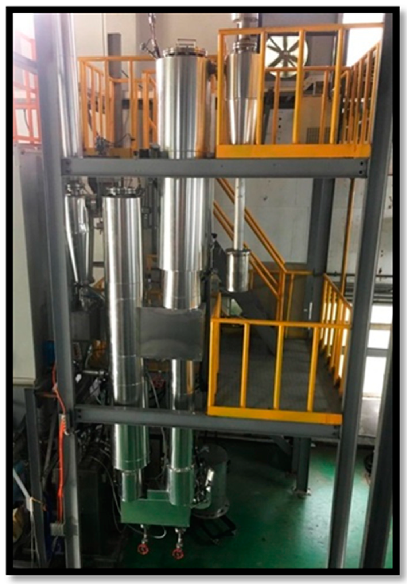
2.2. Basic Platform, Solo Fluidized Bed

The BFB gasification system consisted of a feeding system, gasification chamber, air supply system, syngas clean-up system, tar sampling unit, and syngas analysis system [21]. For controlling experimental conditions, this gasifier was equipped with an electric heating system, whereas the reactor vessel is made of SUS310 stainless steel with an internal diameter of 6.2 cm in the bed region and total height of 580 cm. Inside the tube, silica sand was used as bed material, with 2.6 g/cm3 in density and 505 μm in average particle size.
Feedstock was stored in a silo tank and connected to the gasifier through the feeding system, which was composed of two-stage screw feeders and double pneumatic knife-gate valves. The feeding rate was controlled by the first-stage screw feeder, and the second stage was implemented for transporting the feedstock into the reactor. Between the stages, the double knife valves provided the interim space for the batch inventory and a gastight environment. Air was supplied by two parallel-connected compressors, equipped with buffer tanks for attenuating possible fluctuation. Upstream, the entrance to the gasifier, a preheater was utilized to tune the air temperature. Syngas analysis system included online analysis modules and a batch system. The former displayed the real-time contents of CO, CO2, O2, H2, and CH4 during the experiments, which indicated the timing for sampling the tar and syngas.

2.3. Dual Fluidized Beds

As described before, indirect gasification can achieve nearly nitrogen-free syngas without using an air separation unit (ASU) for supplying pure oxygen or oxygen-rich stream. However, to improve the gasifier performance, pressure drops and solid fractions within the DFB system needed to be controlled [23]. The cold model was based on the Glicksman’s simplified scaling ratios, which determined the particle properties and operating conditions of the cold model [24]. A study running in a cold model of a dual circulating fluidized-bed system for chemical looping processes was presented and focused on solids circulation rates and pressure profiles, which were the key operating parameters in dual reactors [25]. In the present work, a cold flow model was designed by the operating conditions based on the dimensionless analysis, and with the dimension referring to the actual size of the 100 kWth dual fluidized beds for gasification study [10]. Thirteen pressure gauges were equipped for the apparatus and distributed on the two fluidized-bed reactors, as well as the upper loop seal and the lower loop seal (Table 1 and Figure 2a). The vessel was constructed by acrylic material (Figure 2b), of which the characteristics provided the building blocks for the DFB hot model subsequently commissioned at INER.
Table 2 presents the results of dimensionless analysis, including related operating parameters in both the cold model (denoted with subscript C) and the hot model (denoted with subscript H). For example, the physical properties of the bed material (olivine) and the exhaust gas/product syngas in the hot model reactor are listed at the CRH (combustion reactor) and GRH (gasification reactor) columns, respectively. Farrel proposed that dimensionless groups, e.g., De, Ar, Fl, GS*, Fr, and Rep, could be calculated from these parameters in combination with the size of the cold model [26]. However, due to the fact that the designed cold model was based on the actual size of configuration and ambient air, there were only two degrees of freedom (i.e., u and GS,) for the optional variables. Hence, two groups of dimensionless values (Fl and GS*) in the cold model can be the same as (or close to) the counterparts of the hot model. Simultaneously, glass bead was selected as bed material in the cold model.
The operating regimes in fluidized bed are usually characterized by the parameters representing particle and flow properties [27], for which the flow regime diagrams for gas-solid fluidization have been cited in the literature. The relationship for Ar1/3 vs. U* of the cold and the hot molds according to the dimensionless analysis showed that the hydrodynamic properties of the cold mold were very similar to the counterparts of the hot mold, i.e., a bubbling fluidized bed within the gasifier and a fast fluidized-bed within the combustion furnace (Ar1/3 and U* in Table 2). The actual test was carried out by air at ambient temperature. The superficial velocity (uc) of the air in the combustion reactor was set at 2.0, 2.4, and 2.8 m s−1 (equivalent to the following cases: uc/umf is 86.1, 103.3, 120.6; or uc/ut is 1.26, 1.51, and 1.76, respectively).
Following a series of efforts on DFB, a hot model of the pilot test facilities for indirect gasification system was commissioned at INER (Figure 3), for which the design and sizing of the reactors were confirmed with the assistance of process simulation. The flow rates of steam and air required, respectively, for the gasifier and combustor were firstly calculated from a nominal feed rate of biomass; then, the simulated results of the gasifier and combustor could be determined by adjusting the diameter and height of the reactors. The pressure drop of the gas distributor was regulated and the solid volume fraction was inspected. The system PFD (process flow diagram), P&ID (piping and instrumentation diagram), and design charts of equipment were accomplished along the commissioning process. The facilities included gasifier, combustor, cyclone, biomass feeder, bed material feeding apparatus, auxiliary fuel system, steam generating system, gas preheater, MFCs (mass flow controllers), temperature and pressure instrumentation, steel structure, etc. The functional tests for individual unit operation of the pilot test facilities was verified.

3. Results and Discussion

3.1. Baseline Performance Characteristics

The baseline gasification experiments were performed in the 30 kWth bubbling fluidized-bed gasification system as shown in previous work [21], to investigate the effect of various operating parameters, including air equivalence ratio (ER), temperature, feed rate, gasification medium, etc. The equivalent ratio (ER) was defined as the actual air-fuel ratio to the stoichiometric counterpart.

3.1.1. Key Operating Parameters

Gasification process consisted of a series of thermo-chemical reactions under oxygen-lean condition; hence, oxygen content and temperature posed a crucial influence on the reaction products. A test matrix of ER and temperature was set for carrying out gasification experiments of eucalyptus wood chips as reference bases. There are three equivalent ratio (ER = 0.2, 0.3, and 0.4) and three experimental temperature (700, 800, and 900 °C) as the experimental conditions in this study.
The effect of ER on CO and H2 contents in the syngas was addressed in the following. According to Le Chatelier’s Principle, with more air supplying to the gasifier, whole gasification would tend to oxidation that enhances char combustion to generate CO2 and suppresses other contents such as H2, CO, and CH4 of the product gas. As a result, there was more CO2 while less H2 and CO when ER was increased. In contrast, it was shown that CO and H2 increased as ER decreased. The trends are consistent with previous research [2,28,29].
Temperature is another important parameter in gasification. Higher temperature promotes some endothermic reactions, like Boudouard reaction (C + CO2 → 2CO) and water–gas reaction (C + H2O → CO + H2, C + 2H2O → CO2 + 2H2), to produce more CO and H2. When the temperature ascends, CO and H2 increase, which is consistent with the results of previous studies [30,31]. On the other hand, CO/CO2 ratio will be higher as temperature increases. When temperature is higher than 830 °C, the Boudouard reaction will have more effect than the water gas reaction [32]. The development of two-stage gasification which consists of two tandem reactors has been reported in the literature. The raw syngas generated in the first stage was further gasified or cracked again in the second stage, under relatively higher temperature than that in the first stage. This technique increased the syngas yield and H2 content, which was affected by the temperature and indirect gasification technology [33,34].

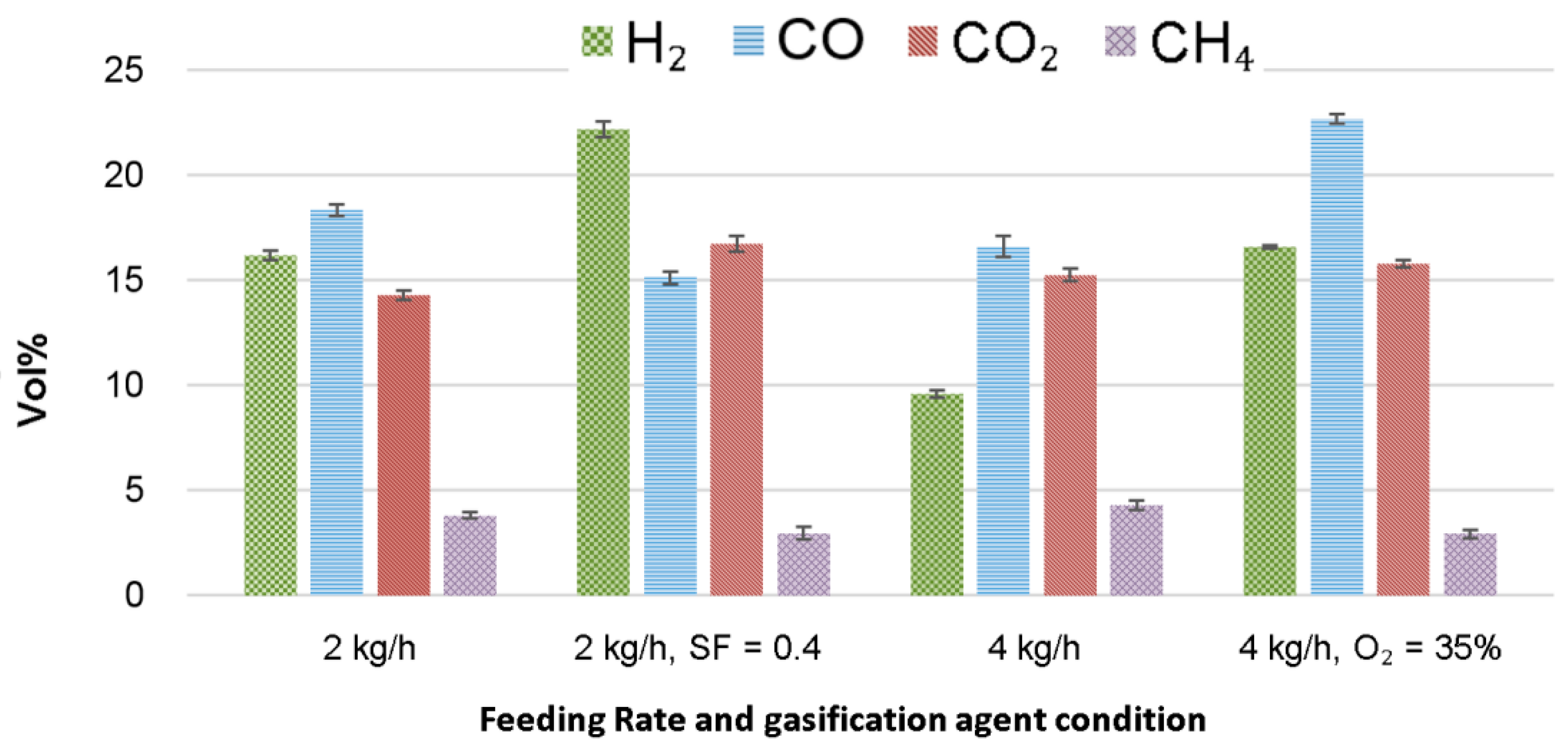
3.1.2. Influence of Gasification Medium

From operational viewpoints, the syngas characteristics can be improved by implementing alternative media, e.g., steam or oxygen-rich gas. Hence, two trial tests were conducted to verify the above scenarios.
The first case addressed the influence of steam. The reference case in Figure 4 was carried out under the following operating conditions: Feedstock mass flow rate 2 (kg/h), temperature 900 °C, and ER 0.3. For comparison, an additional stream of steam with a steam-to-fuel ratio (kg/kg) SF = 0.4 was injected to the reactor. Due to the present equipment limitation, the steam temperature was substantially lower than that in the reactor; nevertheless, it was clearly seen that hydrogen generation was enhanced. Steam injection promoted the forward water–gas shift reaction (CO + H2O → CO2 + H2), which converted CO to CO2 and produced more H2.
Oxygen-rich gas is another candidate for enhancing hydrogen generation. Again in Figure 4, the reference case was carried out under the following operating conditions: Feedstock mass flow rate 4 (kg/h), temperature 900 °C, and ER 0.3. Then, the oxygen content of gasification medium was increased to 35% (compared to ~21% in air); as a consequence, hydrogen generation was enhanced, as was CO content as well. The result verified that the syngas characteristics can be improved under a nitrogen-lean environment, which envisages the potential for the concept of indirect gasification. For the cases shown in Figure 4, the error bars were put in the data. The standard deviations were carried out, based on the four-time experimental results per case.
The test data to address the influence of steam showed that hydrogen generation was enhanced with an additional steam injection to the reactor. It was seen that the existence of steam promoted the water–gas shift (WGS) reaction to generate a higher hydrogen content in the syngas composition. Furthermore, oxygen-rich gas improved the gasification process towards more fractions of both H2 and CO in the syngas.

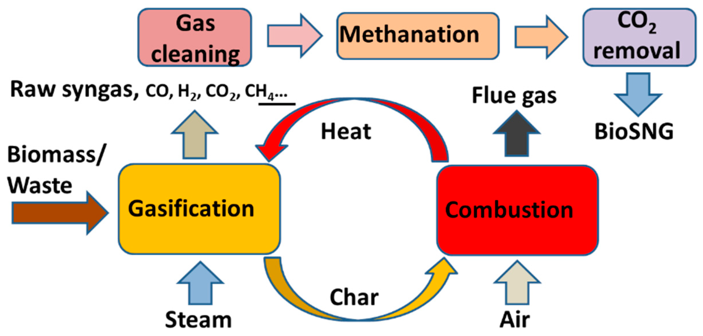
3.2. Study of DFB for Indirect Gasification

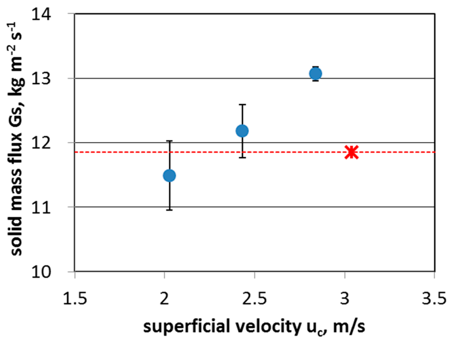
3.2.1. Hydrodynamic Properties of the DFB Cold Model

In examining the cold-flow model (i.e., Figure 2), the other operating parameters (i.e., ug at room temperature) were based on the results of the dimensionless analysis. The variation in the averaged (repeated three times) mass flux of the bed sand versus the flow rate of air is shown in Figure 5, from which it is seen that the mass circulation flux of glass beads increased with the superficial velocity. Compared with the original design value (11.85 kg m−2 s−1) by the dimensionless analysis (red cross in Figure 5), the circulation rate of the bed material (GS ) in the cold model can achieve the designated level at a lower gas velocity (about 2.2 m s−1). In other words, only 75% of the originally estimated value for the flow rate of operating air was needed to achieve the expected GS. This outcome provided a safety factor for the engineering design.
In the DFB, the heat produced in the combustion reactor was transferred to the gasification reactor by the bed material, which then supplied the energy needed for gasifying the feedstock. The circulation rate of the bed material (GS) was the key parameter to maintain the temperature in the gasification reactor. Lower GS will result in decreased bed temperature of the gasifier, and incomplete reactions of volatile and hydrocarbons. The tar content in the syngas will be increased as well with lower gasification temperature [6]. Higher tar content is an issue for the downstream applications, since the loading of tar handling and the operating cost would be increased. On the other hand, lower gas velocity in the combustor is beneficial to the operating cost, due to the fact that lower air volume flow rate requires less power consumption and smaller size of blower.
Based on the nominal operating range in the previous examining results, a fixed operating condition was selected for performing the long-term operation. The average pressures at the height of each measurement location are shown in Figure 6, when uc and ug were equal to 2.4 and 0.15 m s-1, respectively. The pattern was also displayed in multiple tests. The average pressure distribution measured by the system-wide cyclic operation was similar to that of the published literature by the Vienna University of Technology (VUT) [10]. The result also shows that the pressure drop was consistent with the flow direction of the bed sand.
Furthermore, the rate variance of circulating bed material was observed when the gas velocities in the gasifier (ug) and combustor (uc) were changed, as shown in Figure 7. The normal velocity of the air was set on 80% of that estimated by the dimensionless analysis. The operating region was within ±15%. It is shown that the flux variation of the bed material ranged from 11.9 to 13.5 kg m−2 s−1 in Figure 7a. The change within the highest and the lowest flux approached 12.45%, which provided sufficient adjustment ability to the temperature gradient between the two reactors. For the contour map (Figure 7b), it shows that the circulation rate of bed material at the lower-right corner exhibited the largest value, and the smallest circulation rate occurred at the upper-left corner. Hence, the high circulation rate of bed material could be obtained by increasing the gas velocity of the combustor or decreasing the gasifier’s gas flow rate; at that time, more heat was transported when the temperature of the combustion furnace was fixed. Conversely, reducing the air velocity of the combustion furnace or increasing the air velocity of the gasifier led to lower heat delivery, due to slower circulation rate of the bed material.
Moreover, the characteristics of DFB were further analyzed. The multivariate principle was implemented to analyze the point-to-point correlation between the measured pressure points of the dual fluidized-bed system in the cold model. By this analysis, the pressure interaction between the different points can be predicted, which can be used in the future as a reference for the operation of the double bed. If the value of correlation between two points was greater than 0.5, it displayed the change of pressures in the same direction; on the other hand, a value less than −0.5 indicated that the pressure dynamic had different direction. The tested results of the correlation coefficients at the 13 pressure points for the aforementioned three values of uc are plotted in Figure 8. The significant correlations are positively displayed by red mark, the negative is marked as blue region, and green shows the case with small correlation. The figure shows that there was a positive correlation between P4 and P5, that is, the pressure between the two points was more likely to rise or to fall at the same time. Conversely, there was a negative correlation between P1 and P2, P3 and P4, P3 and P5, P9 and P10, as well as P10 and P11.

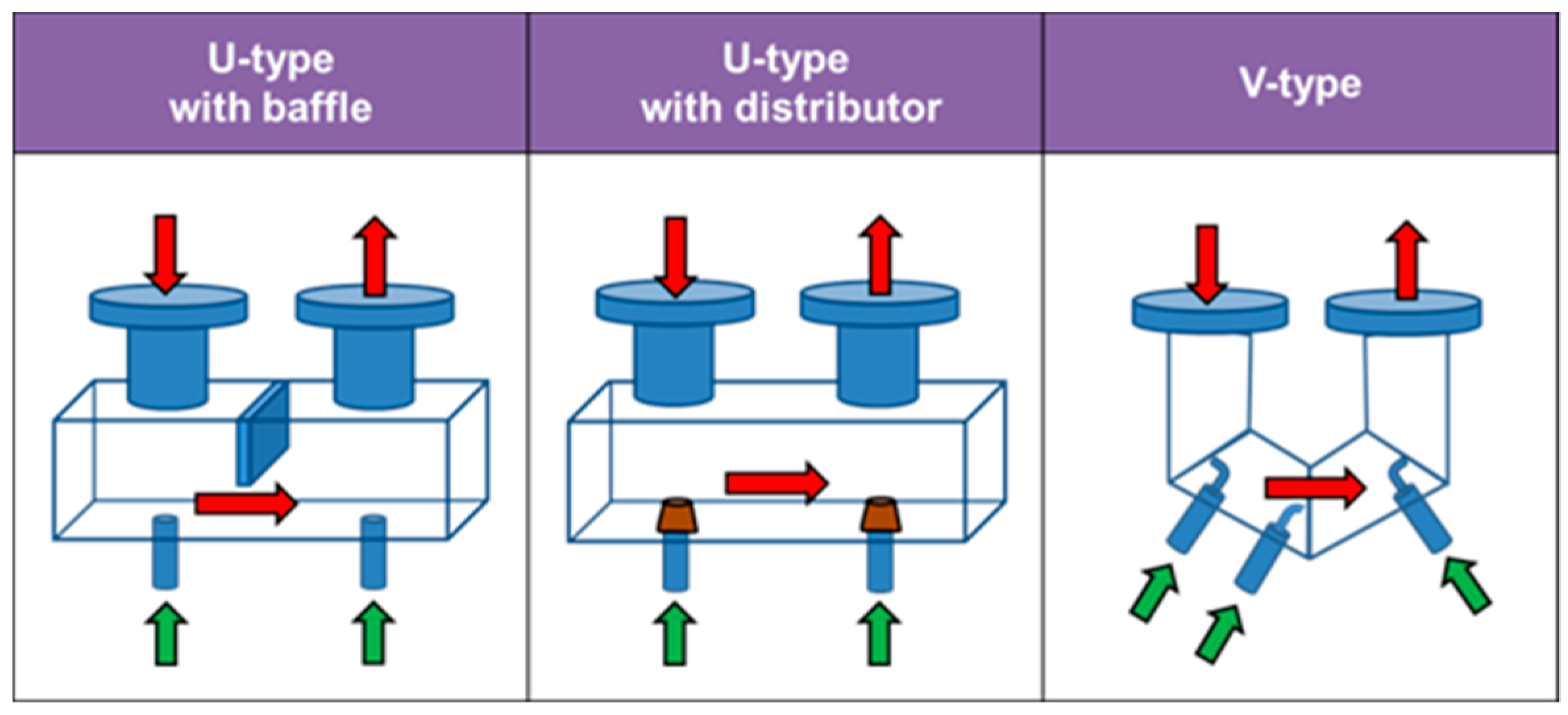
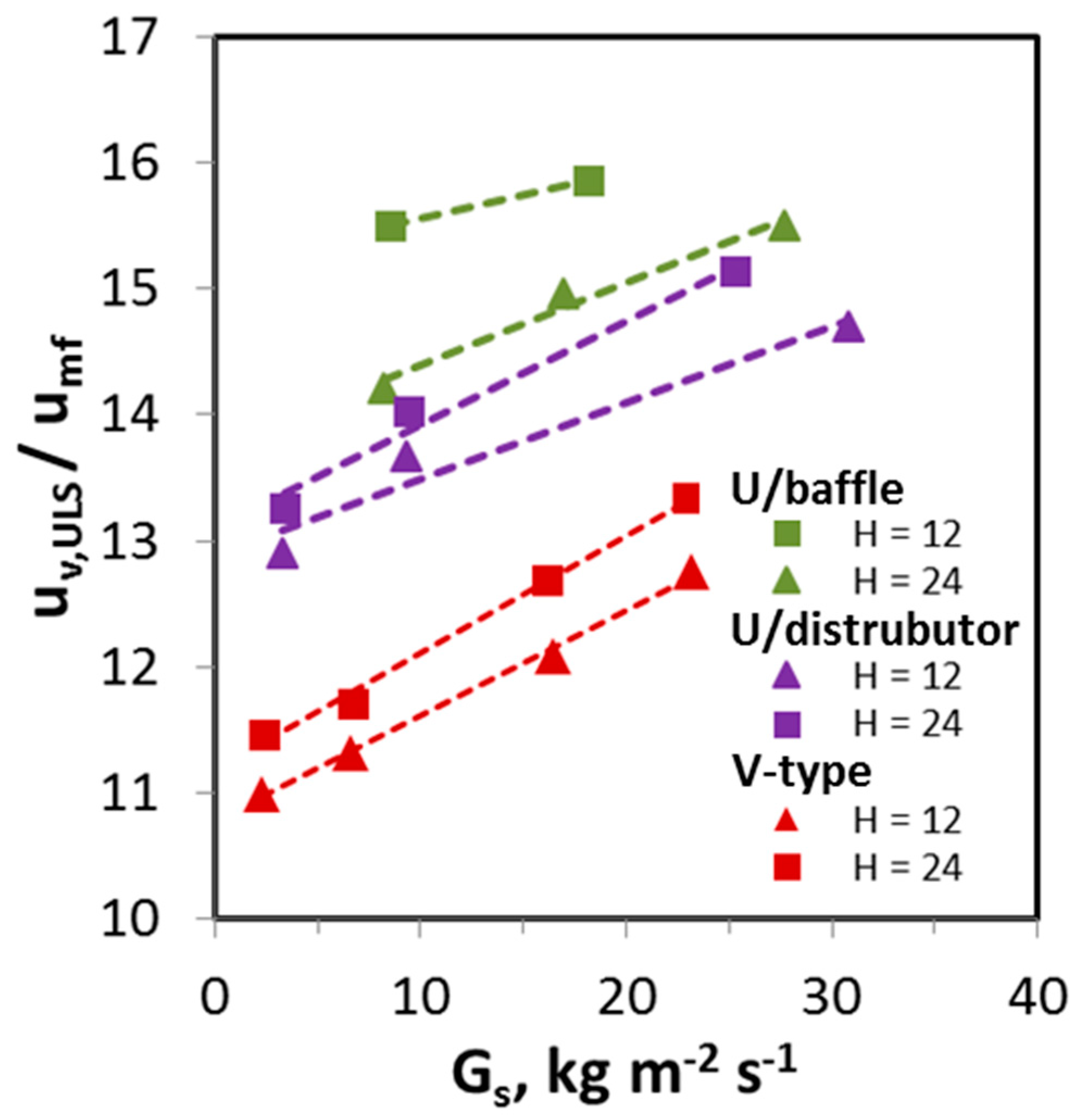
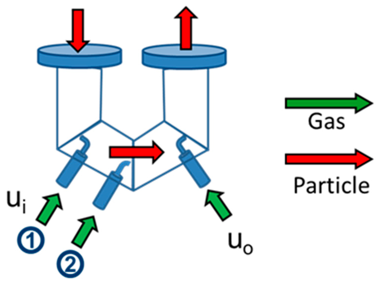
3.2.2. Operating the Cold Model by Loop Seals

Upper Loop Seal

Loop seal is utilized to avoid the penetration of the gases between the combustion reactor and the gasification reactor, as well as to transport the bed material between the two reactors (Figure 2a). For the upper loop seal, the bed material was coming from the combustor and collected there. Then, steam was adopted as the fluidizing gas for driving the bed material to move out the upper loop seal and enter the gasification reactor.
Three types of upper loop seal were tested in the present study to identify the proper one for further study. The configurations shown in Figure 9 are U-type with baffle, U-type with distributor, and V-type, respectively. Two operating parameters were adopted to measure the circulation rate of the bed material. The first one was the bed height at the inlet side, and the other one was the outlet gas volume flow rate. The bed height at the inlet side can provide the pressure drop from the collection of the bed material to overcome the relatively higher pressure in the combustor to the gasification reactor, and to achieve the blocking of gas in the combustor from penetrating to the gasification reactor. Two bed heights (h) of 24 cm and 12 cm were chosen to study the effect on the circulation rate of the bed material. The outlet gas volume flow rate was the critical parameter to decide the bed material moving out the upper loop seal to the gasification reactor. The gas volume flow rate must provide the velocity which is higher than the minimum fluidization velocity. Thus, the gas volume flow rate of minimum fluidization velocity and a value 1.5 times larger were chosen in the study. The gas volume flow rates of minimum fluidization velocity of the U-type and V-type were 30 L/min and 15 L/min, respectively.
The experimental results of the upper loop seals are shown in Figure 10. When the mean velocity (Uv,ULS) in the upper loop seal increased, the circulation rate of the bed material increased in the all types of upper loop seals. The V-type loop seal shows the lowest gas volume flow rate needed to provide the same circulation rate of the bed material, compared to the other two U-type loop seals. Hence, it was beneficial to adopt the V-type loop seal in the study.

Lower Loop Seal

The lower loop seal, called V-type, was made with reference to the shape of VUT. In addition to the location at outlet side (for uo) of the loop seal, the aeration point at seal inlet side (for ui) was designed, for which two positions can be selected (Figure 11). Firstly, the aeration flow rate at the outlet position was set (i.e., uo = 0.42 cm s−1) to a value below umf, so that the bed material would not be blown off; and then, the air flow rate at the inlet position 1 or position 2 was adjusted for individual testing. The gas velocity at the V-type loop seal was defined by combing the both aeration flow rates at the inlet and outlet, i.e., uv = ui + uo.
Figure 12 shows the pressure distribution under three different ui (i.e., uv/umf within 0.7~2.4 @ uc/umf = 103.3). Regardless of the inlet positions, the pressure drops of the upper loop seal (P12–P13) and of the combustor (P7–P11) were increased as increasing uv/umf.
The flux changes of the circulating bed material (GS) under different gas velocity of the loop seal (uv) and the combustor (uc) are shown in Figure 13. Figure 13a shows the result of the velocity variance at the position 1, and Figure 13b shows the counterparts at the position 2. It is obvious that the circulating bed material increased with the increase of the total gas velocity (uv) for the loop seal. Moreover, when the ratio of ux to umf was lower (i.e., uv/umf < 1.55), different gas velocity of the combustor (uc) exhibited similar characteristics and very close value of GS, regardless of the inlet air at position 1 or 2. However, when the uv/umf ratio was greater than 1.55 the variation trend of GS became diversified. Although the GS still increased along with the uc, it will eventually approach an asymptotic value when the inlet air was injected at position 2. The GS change for the inlet air at position 1 was larger than that at position 2, and kept increasing when uv/umf increased. However, it won’t influence the selection of the aeration position for the standard operating area, which was set for GS = 11~13 kg m−2 s−1 (hatched area in the Figure 13). Nevertheless, the outcome reveals that inlet air at position 2 would provide favorably stable flow of circulating bed material from operational viewpoints.

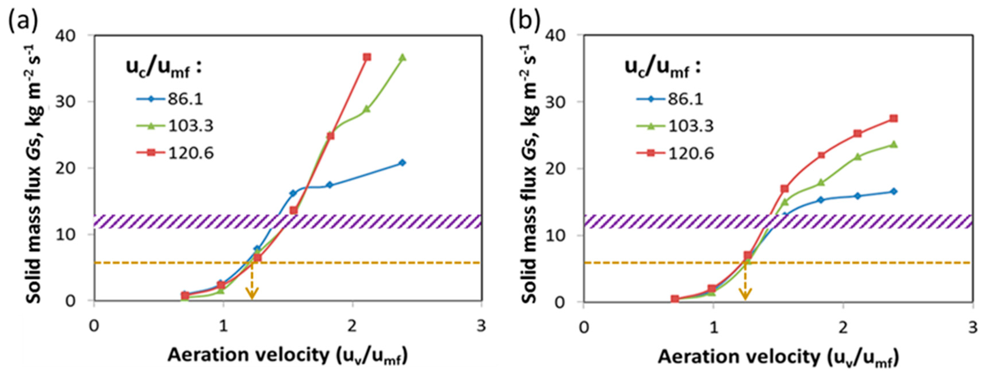
3.2.3. Advanced Dynamic Analysis on the Cold Model

In this section, more dynamic performance of the cold model was examined on the previous parameters to simulate the reliability of the units. Because the aeration velocity (uv) of the lower loop seal changed, the variance of pressure drop is observed in Figure 14 for two fluidized-bed reactors (i.e., gasifier and combustor) and for loop seals (i.e., upper and lower loop seal). The pressure drops of the gasified bed (ΔPg) and of the lower loop seal (ΔPLLS) decreased as the flow rate of exposure air increased, regardless of the position at the inlet and the air positions of the lower loop seal; on the other hand, the pressure drops of the combustion bed (ΔPc) and of the upper loop seal (ΔPULS) were increased as the flow rate of aeration air increased. The front relationship is still true when the combustion reaction bed was aerated with different air velocity. However, the pressure oscillation was more dominated under the lower aeration of the combustion bed.
Finally, the void fraction (ε) of the bed material was calculated by the differential pressure in each measured points. Under different uc/umf and uv/umf, Figure 15 shows the bed sand distribution ratio (i.e., 1 − ε) in the gasifier, and Figure 16 shows the bed sand distribution ratio in the combustor. Because the gasification reactor operated at bubbling mode, the sand distribution in the bed was between 0.5 and 0.6. Similarly, the combustion reactor was operated in fast fluidization regime, therefore the bed sand distribution in the lower dense zone of the reactor was only 0.1 to 0.2. Hence, based on the results of testing, the dual fluidization-bed reactor was in accordance with the fluidization principles. Based on the suggestion of Lim et al. [23], the tested results of the cold system demonstrated the applicability of hydrodynamic performance in DFB.
The experimental results show that GS was mainly affected by the lower loop seal. The effect of the velocity in the combustor was relatively minor, but it can handle the higher GS provided by the lower loop seal. The V-type upper loop seal also showed the ability to transport the bed material in the design condition (full load) and lower loading ones (partial load). The effect of the gas velocity in the gasifier on GS was minor. In other words, the major effect of the GS on the gasifier was the bed height, but it still could work well as GS varies. The partial-load operation of the DFB could be set by adjusting the gas velocity in the lower loop seal. For the case of the 50% operating load, the GS was near the half of design value. The (dimensionless) aeration velocity was found to be around 1.1 by following the line of uc/umf = 86.1, as shown in Figure 13. Finally, the gasifier can be operated under the condition by adjusting the bed height.

3.2.4. Operating Condition and Suggestion of DFB

Following the experimental results and discussions of the cold model of DFB, the circulation rate of the bed material based on the design value can be achieved. The design value of 100% loading operation was verified in the cold model; hence, the hot model could be commissioned, referring to the geometry and size from the cold model. The suggestions for the operating tests in the hot model are shown as follows:
(1)
The circulation rate of the bed material was mainly controlled by the lower loop seal. To change the circulation rate of the bed material in operation, the first step was to set the new condition of the lower loop seal, then follow the flow direction of the bed material to change the conditions of the units.
(2)
The 110% loading operation was achievable by increasing the gas volume flow rates in the gasification and combustion reactors, as the upper and lower loop seals kept the same operating conditions.
(3)
For the case of partial loading of 50%, the major controlling unit was the lower loop seal, while the other units could adjust the needed GS with proper operating condition.
Comprehensive tests were performed on the cold model, and the data analyses were carried out to identify the hydrodynamic characteristics of DFB. These results established the building blocks for the development of DFB and will be utilized to conduct a series of experiments on the hot model commissioned at INER (Figure 3) as follow-up efforts in the near future.

4. Summary and Conclusions

In this study, development of biomass gasification technology with fluidized-bed reactors were conducted to examine the syngas composition under various operating conditions and different structural configuration. Gasification experiments of biomass were performed to investigate the potential means for the enhancement of hydrogen generation.
Conventionally, air is supplied to the reactor as gasification medium. Alternatively, steam or oxygen-rich gas can be utilized to improve the syngas characteristics. Baseline experiments with various operating parameters, including air equivalence ratio (ER) and temperature, were firstly performed in the 30 kWth bubbling fluidized-bed (BFB) gasifier commissioned at INER. Then, trial tests were conducted with the aforementioned operational factors. The test data to address the influence of steam showed that hydrogen generation was enhanced with an additional steam injection to the reactor. It was seen that the existence of steam promoted the water–gas shift (WGS) reaction to generate a higher hydrogen content in the syngas composition. Furthermore, oxygen-rich gas improved the gasification process towards more fractions of both H2 and CO in the syngas.
Two types of reactor configuration based on “indirect gasification technology”, namely dual fluidized beds (DFB) and interconnected fluidized beds (IFB), were surveyed in the present work. To start with, the cold-flow models were generally utilized to visualize and comprehensively study the hydrodynamic characteristics, which can facilitate subsequent investigation into thermo-chemical processes for testing in the hot models.
A series of efforts on DFB were undertaken at INER, where both the cold model and hot model were commissioned. The pilot test facilities of the latter were just established with verified functional tests for unit operation, while follow-up experiments with in situ operating conditions will be pursued in the near future. For the former, dimensionless analysis and comprehensive hydrodynamic testing were carried out systematically. It was confirmed that the circulation mass of the bed material driven by the flow rate of the operating air exceeded the design value, which gave a comfortable safety factor of the engineering design. In addition, the average pressure distribution measured by the system-wide cyclic operation was similar to that of the published literature. In summary, the outcome demonstrated the applicability of this cold model.
The experimental results from the cold model of DFB can provide the guidance for testing the subsequent DFB hot model. Further efforts will be pursued to establish databases for gasification reaction performance and optimal operating parameters. The outcome would be beneficial to extensive research on clean energy and carbon abatement technologies.

Author Contributions

Conceptualization, Y.-P.C. and K.-T.W.; methodology, D.-M.C. and Y.-P.C.; software, D.-M.C. and R.-Y.C.; validation, P.-C.C.; formal analysis, H.-Y.C.; investigation, D.-M.C., P.-C.C., H.-Y.C., and R.-Y.C.; resources, Y.-P.C.; data curation, Y.-P.C.; writing, original draft preparation, D.-M.C. and P.-C.C.; writing, review and editing, Y.-P.C. and K.-T.W.; visualization, K.-T.W.; supervision, Y.-P.C. and K.-T.W.; project administration, Y.-P.C.; funding acquisition, Y.-P.C. All authors have read and agreed to the published version of the manuscript.

Funding

This research was supported by the governmental R&D funding allocated to the Institute of Nuclear Energy Research (INER), Atomic Energy Council, and Ministry of Science and Technology with the grant numbers: MOST 108-3111-Y-042A-122 and MOST 108-3116-F-008-004 -CC1.

Acknowledgments

This research was supported by the governmental grants allocated to the INER (Institute of Nuclear Energy Research) R&D program, “Clean Carbon as Sustainable Energy (CaSE)”, under the framework of National Energy Program (NEP) of Taiwan, ROC. The authors also acknowledge the efforts pursued by the CaSE project teams, both at INER and NCHU (National Chung Hsing University).

Conflicts of Interest

The authors declare no conflict of interest.

Nomenclature

D bed diameter (mm)
dpparticle diameter (μm)
ggravitational acceleration
GSsolid circulation flux (kg/m2/s)
hbed high in inlet of loop seal (cm)
MWmega-watts (power unit, 1000 kW)
uxsuperficial velocity for x (m/s)
Greek letters
ηggas viscosity (Pa/s)
ρggas density (kg/m3)
ρpgas density (kg/m3)
Φshape factor (-)
Components with subscript i in notation
ccombustor
Ccold model
ggasifier
Hhat model
iinlet side of loop seal
mfminimum velocity
ooutlet side of loop seal
tterminal velocity
ththermal
vover all in loop seal
Dimensionless groups
Ar d p 3 ρ g ( ρ p ρ g ) g / η g 2  
De ρ p / ρ g  
Fl u x / u mf  
Fr u x 2 / d p / g  
G S * G S / ρ p / u x  
Re p d p u x ρ g / η g  
U* Re p / Ar 1 / 3  

References

  1. Raizaiyan, J.; Cheremisinoff, N.P. Gasification Technologies; CRC Press: New York, NY, USA, 2005. [Google Scholar]
  2. Alauddin, Z.A.B.Z.; Lahijani, P.; Mohammadi, M.; Mohamed, A.R. Gasification of lignocellulosic biomass in fluidized beds for renewable energy development: A review. Renew. Sust. Energy Rev. 2010, 14, 2852–2862. [Google Scholar] [CrossRef]
  3. Basu, P. Combustion and Gasification in Fluidized Beds; CRC Press: New York, NY, USA, 2006. [Google Scholar]
  4. Bain, R.L. An overview of biomass gasification. In Proceedings of the 2004 AIChE Spring National Meeting, New Orleans, LA, USA, 25–29 April 2004; pp. 547–552. [Google Scholar]
  5. Thunman, H.; Lind, F.; Breitholtz, C.; Berguerand, N.; Seemann, M. Using an oxygen-carrier as bed material for combustion of biomass in a 12-MWth circulating fluidized-bed boiler. Fuel 2013, 113, 300–309. [Google Scholar] [CrossRef]
  6. Motta, I.L.; Miranda, N.T.; Filho, R.M.; Maciel, M.R.W. Biomass gasification in fluidized beds: A review of biomass moisture content and operating pressure effects. Renew. Sust. Energy Rev. 2018, 94, 998–1023. [Google Scholar] [CrossRef]
  7. Jeremiáš, M.; Pohořelý, M.; Svoboda, K.; Skoblia, S.; Beňoc, Z.; Šyc, M. CO2 gasification of biomass: The effect of lime concentration in a fluidised bed. Appl. Energy 2018, 217, 361–368. [Google Scholar] [CrossRef]
  8. Gómez-Barea, A.; Ollero, P.; Leckner, B. Optimization of char and tar conversion in fluidized bed biomass gasifiers. Fuel 2013, 103, 42–52. [Google Scholar] [CrossRef]
  9. Corella, J.; Toledo, J.M.; Molina, G. A review on dual fluidized-bed biomass gasifiers. Ind. Eng. Chem. Res. 2007, 46, 6831–6839. [Google Scholar] [CrossRef]
  10. Koppatz, S.; Pfeifer, C.; Hofbauer, H. Comparison of the performance behaviour of silica sand and olivine in a dual fluidised bed reactor system for steam gasification of biomass at pilot plant scale. Chem. Eng. J. 2011, 175, 468–483. [Google Scholar] [CrossRef]
  11. van der Drift, B. Commercialisation of WtE through gasification technology developed by ECN. Symposium on Renewable Energy and Products from Biomass and Waste. In Proceedings of the IEA TAsk 33 Workshop, Ponferrada, Spain, 11–13 May 2015. [Google Scholar]
  12. Kumagai, T. Fluidized bed gasification and combustion of biomass. In Proceedings of the 75th IEA-FBC Meeting 2017, Skive, Denmark, 23–25 October 2017; Available online: https://www.processeng.biz/iea-fbc.org/upload/75_06-Tomoyoshi%20Kumagai.pdf (accessed on 18 December 2019).
  13. Ohshita, T. Hydrogen production by gasification of biomass. Suiso. Enerugi. Shisutemum 2003, 28, 93–100. (In Japanese) [Google Scholar]
  14. Bengtsson, K. Twin-Bed Gasification Concepts for Bio-SNG Production; Lund University: Lund, Sweden, 2007. [Google Scholar]
  15. Kunii, D. Chemical reaction engineering and research and development of gas solid systems. Chem. Eng. Sci. 1980, 35, 1887–1911. [Google Scholar] [CrossRef]
  16. Korbee, R.; Schouten, J.C.; van den Bleek, C.M. Modelling interconnected fluidized bed systems. AICHE Symp. Ser. 1991, 87, 70–77. [Google Scholar]
  17. Korbee, R.; Snip, O.C.; Schouten, J.C.; van den Bleek, C.M. Rate of solids and gas transfer via an orifice between partially and completely fluidized beds. Chem. Eng. Sci. 1994, 49, 5819–5832. [Google Scholar] [CrossRef]
  18. Snip, O.C.; Korbee, R.; Schouten, J.C.; van den Bleek, C.M. The Influence of hydrodynamics on the performance of an interconnected fluidized bed system for regenerative desulfurization in coal conversion processes. AICHE Symp. Ser. 1995, 91, 82–92. [Google Scholar]
  19. Snip, O.C.; Woods, M.; Korbee, R.; Schouten, J.C.; van den Bleek, C.M. Regenerative removal of SO2 and NOx for a 150 MWe power plant in an interconnected fluidized bed facility. Chem. Eng. Sci. 1996, 51, 2021–2029. [Google Scholar] [CrossRef] [Green Version]
  20. Wu, K.T.; Wang, J.S.; Lee, H.F.; Hwang, S.J.; Lee, H.T. Gasification of refuse derived fuel in an interconnected fluidized bed gasifier. In Proceedings of the 9th Asian Conference on Fluidized-Bed and Three-Phase Reactors 2004, Taipei, Taiwan, 21–24 November 2004; pp. 97–102. [Google Scholar]
  21. Hsu, H.T.; Lin, S.C.; Chyou, Y.P. Gasification of solid fuels in a fluidized-bed reactor. In Proceedings of the 13th International Conference on Combustion & Energy Utilization 2016, Taipei, Taiwan, 2–5 October 2016; p. 260021. [Google Scholar]
  22. Chyou, Y.P.; Chang, W.C.; Tung, Y.C.; Chen, P.C.; Chein, R.Y.; Wu, K.T. Experimental study of syngas generated form biomass pellet in an interconnected fluidized-bed gasifier. In Proceedings of the 9th International Freiberg Conference on IGCC & XtL Technologies 2018, Berlin, Germany, 3–8 June 2018; pp. 22–24. [Google Scholar]
  23. Lim, M.T.; Saw, W.-L.; Pang, S. Effect of fluidizing velocity on gas bypass and solid fraction in a dual fluidized bed gasifier and a cold model. Particuology 2015, 18, 58–65. [Google Scholar] [CrossRef]
  24. Bidwe, A.R.; Hawthorne, C.; Xizhi, Y.; Dieter, H.; Scheffknecht, G. Cold model study of a dual fluidized bed system for the gasification of solid fuels. Fuel 2014, 127, 151–160. [Google Scholar] [CrossRef]
  25. Pröll, T.; Rupanovits, K.; Kolbitsch, P.; Bolhàr-Nordenkampf, J.; Hofbauer, H. Cold flow model study on a dual circulating fluidized bed system for chemical looping processes. Chem. Eng. Technol. 2009, 32, 418–424. [Google Scholar] [CrossRef]
  26. Farrel, P.A. Hydrodynamic Scaling and Solids Mixing in Pressurized Bubbling Fluidized Bed Combustors. Ph.D. Thesis, MIT, Cambridge, MA, USA, 1996. [Google Scholar]
  27. Grace, J.R. Contacting modes and behaviour classification of gas-solid and other two-phase suspensions. Can. J. Chem. Eng. 1986, 64, 353–363. [Google Scholar] [CrossRef]
  28. Lv, P.; Yuan, Z.L.; Ma, C.W.; Chen, Y.; Zhu, J. Hydrogen-rich gas production from biomass air and oxygen/steam gasification in a downdraft gasifier. Renew. Energy 2007, 32, 2173–2185. [Google Scholar] [CrossRef]
  29. Qin, K.; Lin, W.; Jensen, P.A.; Jensen, A.D. High-temperature entrained flow gasification of biomass. Fuel 2012, 93, 589–600. [Google Scholar] [CrossRef]
  30. Karmakar, M.K.; Datta, A.B. Generation of hydrogen rich gas through fluidized bed gasification of biomass. Bioresour. Technol. 2011, 102, 1907–1913. [Google Scholar] [CrossRef]
  31. Umeki, K.; Namioka, T.; Yoshikawa, K. The effect of steam on pyrolysis and char reactions behavior during rice straw gasification. Fuel Process. Technol. 2012, 94, 53–60. [Google Scholar] [CrossRef]
  32. Kantarelis, E.; Donaj, P.; Yang, W.; Zabaniotou, A. Sustainable valorization of plastic wastes for energy with environmental safety via High-Temperature Pyrolysis (HTP) and High-Temperature Steam Gasification (HTSG). J. Hazard. Mater. 2009, 7, 675–684. [Google Scholar] [CrossRef] [PubMed]
  33. Lin, C.-L.; Chou, J.-D.; Weng, W.-C. Partition of Cu and Pb in a two-stage fluidized-bed waste gasification system. Appl. Sci. 2019, 9, 1576. [Google Scholar] [CrossRef] [Green Version]
  34. Soni, C.G.; Wang, Z.; Dalai, A.K.; Pugsley, T.; Fonstad, T. Hydrogen production via gasification of meat and bone meal in two-stage fixed bed reactor system. Fuel 2009, 88, 920–925. [Google Scholar] [CrossRef]
Figure 1. Concept and applications of indirect gasification technology.
Applsci 10 00002 g001
Figure 2. The cold model of DFB (Dual Fluidized Beds) gasification system: (a) Sketch of the cold model and the location of the pressure transmitters (P1~P13), and (b) the photo of the test apparatus.
Applsci 10 00002 g002
Figure 3. The hot model of DFB gasification system.
Applsci 10 00002 g003
Figure 4. Comparison of syngas composition with various gasification media.
Applsci 10 00002 g004
Figure 5. The flux of the bed material in combustor under different superficial gas velocity.
Applsci 10 00002 g005
Figure 6. Average pressure distribution on the DFB.
Applsci 10 00002 g006
Figure 7. Relationship between gasification bed and combustion bed aeration amount on the circulation flux of the bed sand: (a) the Gs response (3D) surface, and (b) equivalent Gs (contour lines) under different aeration conditions.
Applsci 10 00002 g007
Figure 8. Analysis of mutual interference between pressure measurement points under different test conditions.
Applsci 10 00002 g008
Figure 9. Three types of upper loop seal and aeration position.
Applsci 10 00002 g009
Figure 10. Test data of the three types of upper loop seal.
Applsci 10 00002 g010
Figure 11. V-type lower loop seal and aeration position.
Applsci 10 00002 g011
Figure 12. Pressure distributions under different aeration conditions.
Applsci 10 00002 g012
Figure 13. Change of the circulating bed material when air velocity adjustment at (a) position 1 and (b) position 2.
Applsci 10 00002 g013
Figure 14. Changes of the pressure drop for the four units in cold module with the different aeration velocity at lower loop seal positions.
Applsci 10 00002 g014
Figure 15. Distribution ratio of bed sand in gasifier under different operating conditions (the values of uv/umf are shown as legend in the plots).
Applsci 10 00002 g015
Figure 16. Distribution ratio of bed sand in combustor under different operating conditions (the values of uv/umf are shown as legend in the plots).
Applsci 10 00002 g016
Table 1. Units/parts and pressure gauge positions in the cold flow model.
Units/Parts#GaugeType of Fluidized-Bed
GasifierP1~P4Bubbling
CombustorP7~P11Fast
Upper Loop Seal (ULS)P12~P13
Lower Loop Seal (LLS)P5~P6
Table 2. The results of dimensionless analysis.
Bed MaterialCRHCRCGRHGRC
OlivineGlassOlivineGlass
ηG4.50 × 10−51.83 × 10−53.59 × 10−51.83 × 10⁻⁵
ρG0.291.150.201.15
ux9.203.060.660.19
ρP2.852.422.852.42
dP520.00200.00520.00200.00
Ф0.800.800.800.80
D102.30102.30270 × 270270 × 270
GS42.2411.85
De9796.982095.5314,103.042095.53
Ar564.21652.06616.49652.06
Fl120.45130.006.888.00
GS*1.61 × 10−31.60 × 10−3
Fr16,608.264780.7685.3218.10
ReP30.9338.581.932.37
Ar1/38.268.678.518.67
U*3.744.450.230.27
Note: The gasifier is a square vessel with the dimensions of 270 mm × 270 mm.

