Article

Driverless Bus Path Tracking Based on Fuzzy Pure Pursuit Control with a Front Axle Reference

School of Automation, Central South University, Changsha 410083, China
*
Authors to whom correspondence should be addressed.
Appl. Sci. 2020, 10(1), 230; https://doi.org/10.3390/app10010230
Submission received: 12 October 2019 / Revised: 21 December 2019 / Accepted: 24 December 2019 / Published: 27 December 2019
(This article belongs to the Section Computing and Artificial Intelligence)

Abstract

:

Featured Application

This work is used for driverless vehicles, especially for long wheelbase vehicles.

Abstract

Currently, since the model of a driverless bus is not clear, it is difficult for most traditional path tracking methods to achieve a trade-off between accuracy and stability, especially in the case of driverless buses. In terms of solving this problem, a path-tracking controller based on a Fuzzy Pure Pursuit Control with a Front Axle Reference (FPPC-FAR) is proposed in this paper. Firstly, the reference point of Pure Pursuit is moved from the rear axle to the front axle. It relieves the influence caused by the ignorance of the bus’s lateral dynamic characteristics and improves the stability of Pure Pursuit. Secondly, a fuzzy parameter self-tuning method is applied to improve the accuracy and robustness of the path-tracking controller. Thirdly, a feedback-feedforward control algorithm is devised for velocity control, which enhances the velocity tracking efficiency. The proportional-integral (PI) controller is indicated for feedback control, and the gravity acceleration component in the car’s forward direction is used in feedforward control. Finally, a series of experiments is conducted to illustrate the excellent performances of proposed methods.

Graphical Abstract

1. Introduction

With the development of new energy and the upgrading of buses, the technology of the driverless bus has become a greater research prospect [1]. Nowadays, many researchers are devoted to path planning and path tracking [2,3]. One of the most basic and key technologies in driverless buses is path tracking [4]. A path-tracking controller is applied to control the driverless bus to follow the desired path and velocity [5,6]. Generally, path tracking algorithms are divided into lateral and longitudinal control.
The lateral controller controls the driverless bus to track a desired path. Some model-free methods, such as proportional-integral-derivative (PID) [7,8,9], fuzzy logic control (FLC) [10,11], and sliding model control (SMC) [12,13,14], are applied. Those algorithms perform well even when the model of the driverless bus is vague. However, they need different parameters to various conditions, which improve the complexity of path-tracking algorithms. Yu proposes an adaptive rolling optimization controller with preview window to track the desired path [15]. It is built on PID, and does not require a high-precision bus model. The robustness of the adaptive rolling optimization controller is poor, too. Meanwhile, some model-based algorithms, such as Stanley, Pure Pursuit (PP) [16], Linear Quadratic Regulator (LQR) [17], and Model Predictive Control (MPC) [18], are provided. The Stanley method is based on the vehicle kinematic model [19]. Stanley uses the lateral error and heading error between the car and the desired path to calculate the steering angle. The tracking accuracy and robustness are good if the velocity is under 15 km/h. However, since the bus’s lateral dynamic characteristics are ignored, Stanley performs poorly if the velocity increases to 20 km/h. PP also uses the vehicle kinematic model [16]. Equally, PP performs poorly if the velocity increases. MPC uses the dynamic model of vehicle, and it certainly performs well if the model describes the car well [20]. To improve the stability and tracking accuracy, Yao applies MPC with longitudinal speed compensation [21]. Since the model of the driverless bus is unclear, these model-based methods need to be improved. To solve the problem of path-tracking in driverless buses, a path-tracking controller based on Fuzzy Pure Pursuit Control with a Front Axle Reference (FPPC-FAR) is proposed in this paper.
The velocity of the driverless bus is controlled by the longitudinal controller. Usually, PID is applied to track the desired velocity [22]. To reject the unknown disturbance of the car, Wang adopted constant time headway (CTH) strategy to design a longitudinal controller based on MPC [23]. Kim proposed a car path prediction employing yaw acceleration for adaptive cruise control [24]. These studies only consider the model of the car; the influence of road slope is not considered. Since the mass changes a great deal according to the number of passengers in the driverless bus, not only does the model of the driverless bus change significantly, but the road slope also influences the longitudinal control [25]. In this paper, a feedforward controller is introduced to reduce the impact of the road slope. Meanwhile, the PI is used in the feedforward controller to track the desired velocity.
The main contributions of this paper are listed as follows:
(1)
For lateral control, a FPPC-FAR path-tracking controller is proposed. Firstly, Pure Pursuit Control Based on a Front Axle Reference (PPC-FAR) path-tracking controller is adopted. It moves the reference point of Pure Pursuit to the front axle to relieve the ignorance’s influence on lateral control. A coefficient is also added to merge the difference between the proposed model and the real bus. Secondly, the look-ahead distance and coefficient are provided by a fuzzy logic interface machine, which improves the accuracy and robustness of the path-tracking controller.
(2)
For longitudinal control, a feedback-feedforward control algorithm is constructed. In feedback control, a proportional-integral (PI) controller is utilized to track the desired velocity. To avoid the jump of desired velocity, the Tracking Differentiator (TD) is introduced to calculate the transient profile of the desired velocity [26]. In feedforward control, the component of gravitational acceleration is applied as the compensation to deceleration. Furthermore, the compensation of the desired velocity is also calculated according to the road slope, which relieves the effect of the road slope.
The remainder of this paper is organized as follows: Section 2 introduces the model of the driverless bus and proposes some assumptions about the model and the details of FPPC-FAR and feedback-feedforward algorithm. Section 3 gives several simulation results and discusses the advantages of the proposed methods. Section 4 implements the path-tracking algorithm in a real bus, and describes the performances of the controller. Section 5 provides a succinct conclusion.

2. Controller Design

As shown in Figure 1, the path-tracking controller is divided into lateral control and longitudinal control. Lateral control calculates the steering angle to track the desired path, and longitudinal control cause deceleration to follow the desired velocity. In this section, the model of the driverless bus is proposed in Section 2.1. Then the controller is introduced with respect to lateral control and longitudinal control in Section 2.2 and Section 2.3.

2.1. The Model of the Driverless Bus

The kinematic model of the driverless bus is shown in Figure 2. It collapses the two front wheels into a single wheel at the center of the front axles. Meanwhile, the two rear wheels are also collapsed into a single wheel at the center of rear axles. Furthermore, there is no lateral slip in the wheels, and only the front wheel is steerable. Then, the bicycle model is mapped into a two-dimensional plane. δ is the steering angle. ( x f , y f ) is the center of the front axle. Equally, ( x r , y r ) is the center of rear axle. L is the wheelbase. The heading of the bus is represented as θ .
Restricting the model to motion in a plane, the kinematic model [16] of the bus is defined in Equation (1):
[ x ˙ y ˙ θ ˙ ] = [ cos ( θ ) sin ( θ ) tan ( δ ) / L ] v
where v is the velocity of the bus, and ( x , y ) is the position of the bus.
According to the kinematic model of driverless bus, the relationship between R and δ is represented as Equation (2):
tan ( δ ) = L / R
where R is the radius of the circle.
It is obvious that, if the steering angle does not change, the center of the rear axle moves along an arc and the center of the arc is O . Equally, the center of the front center also moves along an arc, and the center of the arc is O .
The extended kinematic bicycle model is presented in Figure 3. The steering angle is determined as Equation (3):
tan ( δ ) = L / R
In Figure 3, arc 1 and arc 2 are arcs of the rear axle center and front axle center, but R < R . The relationship of R and R is shown in Equation (4):
R 2 = L 2 + R 2
It is difficult to obtain an accurate model of a driverless bus. It is assumed that the extent of the kinematic model is feasible for the driverless bus under low-velocity conditions. Figure 4 shows the overview of the driverless bus and sensors. The bus’s parameters are provided at Table 1 and it is an actuated-by-wire electrical bus (AWEB). Statuses of driverless bus, such as velocity, heading angle, and positions, are obtained from GPS/IMU (provided by StarNeto, Beijing, China).

2.2. Lateral Control

As shown in Figure 5, the lateral controller is composed of PPC-FAR and a fuzzy logic inference machine. PPC-FAR calculates the desired steering angle to track the desired path. Meanwhile, the fuzzy logic inference machine is provided to turn the suboptimal parameters of PPC-FAR according to the desired path and the current velocity of the driverless bus.

2.2.1. Pure Pursuit Controller with a Rear Axle Reference

The PP is built based on the vehicle kinematic model [16]. It connects the rear center of the vehicle to a preview point with an arc. The arc passes the preview point and it is tangent to the heading of the driverless bus. Furthermore, the steering angle is determined by the arc.
Figure 6 shows the rules in PP. The preview point ( x d , y d ) is calculated according to a look-ahead distance l d . Using the law of sines to Figure 6 results in Equation (5):
l d sin ( 2 α ) = R sin ( π 2 α )
where 2 α is the angle between the driverless bus heading vector and the forward vector. Based on the kinematic bicycle model, the steering angle of PPC-RAR is set as:
δ = tan 1 ( 2 L sin ( α ) l d )
where δ is the steering angle.

2.2.2. Pure Pursuit Controller with a Front Axle Reference

Since the kinematic model ignores the lateral dynamic characteristics of the driverless bus [15], PPC-RAR achieves poor tracking performance in the driverless bus. Ignorance results in the oscillation of the driverless bus. Only adjusting the look-ahead distance is not efficient enough. In that case, the PP is modified by moving the reference to the front axle to relieve those influences.
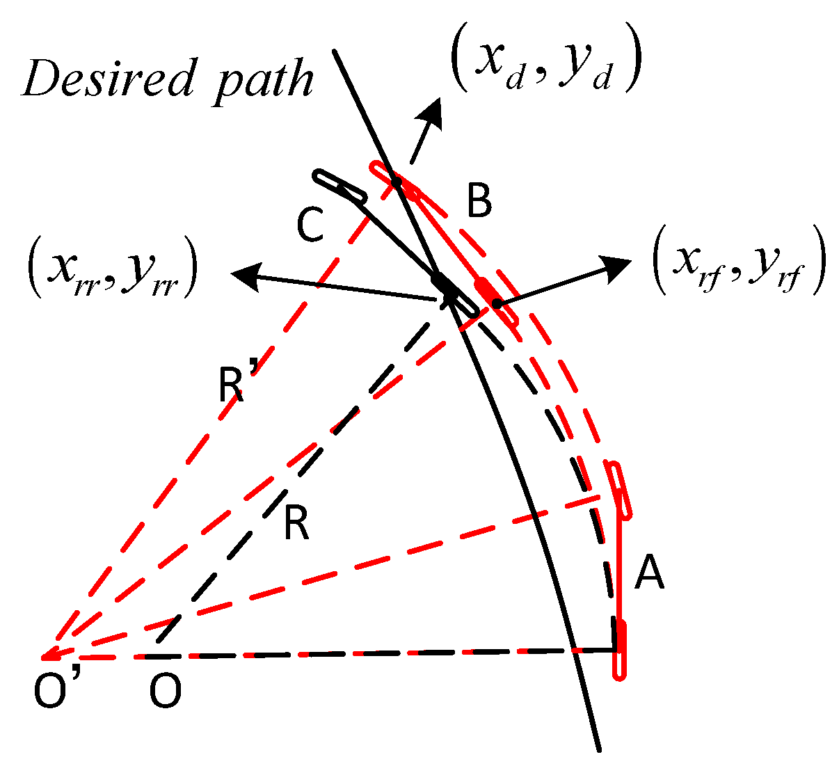
As shown in Figure 7, PPC-RAR calculates the desired steering angle by ( x r r , y r r ) . However, PPC-FAR uses ( x d , y d ) to obtain the radius R and then calculates the steering angle. It is evident that the radius of PPC-RAR is larger than PPC-FAR. As the assumption in Section 2, the larger radius results in a smaller gap between the kinematic model and the real bus. In that case the instability caused by the kinematic model is released in PPC-FAR. The benefits of the front axle reference are verified in Section 3.
The PPC-FAR is illustrated in Figure 8. O is the circle center and R is the radius of the arc. l d is the look-ahead distance. A is the center of the front axle. B is the preview point. C is the middle point of A and B . D is the center of the rear axle. O is the intersection point of line O C and line O D .
According to the extended kinematic model, the steering angle of PPC-FAR is calculated as:
δ = tan 1 ( L R 2 + L 2 )
where δ is the steering angle in PPC-FAR.
Snider verifies the relationship between the tracking accuracy and stability in [16]. Similarly, to the traditional PP algorithm, tracking accuracy is scarified to improve the stability of path tracking. The look-ahead distance is calculated as k · v t ( k is coefficient and v t is current velocity). However, if the velocity is close to zero, the look-ahead distance becomes zero, too. That causes an unstable control system. To solve this problem, Equation (8) is applied to calculate look-ahead distance l d :
l d = k l · v   +   L o f f s e t
where k l is the proportional coefficient, and L o f f s e t represents the offset of the look-ahead distance.
Although some changes are introduced to cancel out the influence caused by the ignorance in the kinematic model, there still exists a gap between the geometric model and the real bus, especially in high-speed and large curvature conditions. The k in Equation (9) is used to eliminate the error between proposed model with the real bus:
δ = k · tan 1 ( L R 2 L 2 )

2.2.3. Fuzzy Pure Pursuit with Front Axle Reference

In this section, to improve the tracking accuracy and robustness of PPC-FAR, a fuzzy logic inference machine is adopted to calculate the appropriate k and l d . The input quantities of the fuzzy logic inference machine are defined as the curvature of the desired path ρ and the velocity of the driverless bus v . Meanwhile, k and l d are used as the output quantities. The basic domain of v is [0, 20], the basic domain of ρ is [0, 0.2], the basic domain of l d is [3, 25], and the basic domain of k is [0.5, 1].
As shown in Figure 9, the membership function is gaussmf type [6]. Both the inputs and outputs are qualitative into seven sets, denoted as NB, NM, NS, ZO, PS, PM, and PB, where NB is negative big, and PB is positive big.
The rule bases of the fuzzy logic inference machine are established based on the trial and error in the real bus experiments. There are two fundamental principles:
(1)
When ρ is small and v is large, in order to achieve a trade-off between accuracy and stability of PPC-FAR, k and l d should be large.
(2)
When ρ is large and v is small, in order to guarantee the tracking accuracy and merge the gap between real bus and kinematic model, k and l d should be small.
The rule bases of the fuzzy logic inference machine are shown in Table 2 and Table 3. Each rule in the rule base are implemeted in the IF-THEN form, and Figure 10 shows the interface of the outputs.
The center of gravity method is adopted as the defuzzification method, which is shown as Equation (10):
u = i = a b u c ( z i ) z i i = a b u c ( z i )
where u is an accurate output value; z i denotes the fuzzy inference output value; u c ( z i ) is the membership value of z i ; a and b are, respectively, the upper and lower bounds of the fuzzy set theory domain of the output variables.

2.3. Longitudinal Control

The velocity of the driverless bus is divided into acceleration control and deceleration control. Since the acceleration is controlled by the VCU of the driverless bus, and only the deceleration is controllable, this section mainly concerns deceleration control. The structure of the longitudinal control is shown in Figure 11.
In Figure 11, the feedback control mainly focuses on deceleration a f b which is calculated by the PI controller. TD is applied to calculate the fast tracking of the desired velocity which is shown as v d . The feedforward controller provides the compensation of deceleration a f f and velocity v 1 according to the road slope. Compensations are used to release the influence of the road slope.
The feedback-forward control algorithm is introduced to deceleration. The deceleration is calculated by Equation (11):
a = a f f + a f b
where a [ a min , a max ] . The deceleration is negative, thus, a min a max 0 .
The local path planning calculates v d and it only gives the limit velocity rather than a velocity curve. If the driverless bus needs to stop, the desired velocity jumps to 0. To smooth the desired velocity, TD is applied to calculate the fast tracking of the desired velocity [27]. The main idea of TD is that there exists a curve that v d ( k ) tracks v d ( k ) without overshoot, and the curve is defined by the discrete time optimal control (DTOC) law [28]. In this paper, the fast tracking of the desired velocity is used as the target in PI.
The longitudinal system is a discrete-time double-integral system [28]. The discrete algorithm of TD is given as Equation (12):
{ u ( k ) = f ( v d ( k ) v d , v ˙ d ( k 1 ) , r , h ) v d ( k ) = v d ( k 1 ) + h · v ˙ d ( k ) v ˙ d ( k ) = v ˙ d ( k 1 ) + h · u ( k )
where v d is the desired velocity. v d ( k ) is the fast tracking of the desired velocity. r denotes the fast factor. h indicates the step length. f ( · ) is the discrete time optimal control (DTOC) law. u ( k ) is the outputs of the DTOC. k is the control step. The law of DTOC is shown as Equation (13).
f s t = f ( x 1 , x 2 , r , h ) { d = r · h , d 0 = h · d y = x 1 + h · x 2 , a 0 = d 2 + 8 · r · | y | a = { x 2 + ( a 0 d ) · s i g n ( y ) | y | > d 0 x 2 + y / h | y | d 0 f = { r · s i g n ( a ) | a | > d r · a / d | a | d
where s i g n ( · )   is the symbolic function.
Figure 12 illustrates the different transient profiles of desired velocities with different r and h . It is obvious that the fast tracking of the desired velocity is smooth. That certainly improves the input quality of PI. Furthermore, if r decreases and h increases, TD tracks the desired velocity faster. Thus, the appropriate fast-tracking curve of the desired velocity is adjusted by r and h .
In feedback control, discrete PI is utilized for decelerating control, which is shown as Equation (14). Furthermore, only errors between t and t + b 1 are used in the integral:
a ( k ) = k p e v ( k ) + k i i = k b + 1 k e v ( i )
where k p , k i are coefficients and b is the integral episode.
Feedforward control is introduced to cancel out the impacts of gravity acceleration. The component of gravity acceleration in the forward direction of the driverless bus is set as the compensation of deceleration. At the same time, the compensation of the desired velocity is calculated according to the road slope.
Especially, the road slope is obtained from the IMU. According to Newton’s second law, the gravitational acceleration component in the forward direction of the driverless bus, which is shown in Equation (15), is used as the compensation of deceleration:
a f f = g · sin ( s l o p e )
where g is the gravitational acceleration ( g = 9.8 m/s2), and s l o p e is the road slope.
Similarly, the desired velocity compensation in TD control is calculated according to the road slope. It is calculated as:
v 1 = | k v * S l o p e |
where k v is the proportionality coefficient.

3. Simulations

The simulations are carried out in Matlab (provided by Mathworks, United States) and TruckSim (provided by Mechanical Simulation, United States). Especially, a high-precision model of AWEB is built in TruckSim. The major parameters of the model are shown in Figure 13 and Table 1.
In the high-precision model, the cornering stiffnesses are 6500 (N/rad) and 5200 (N/rad). The mass is 17,800 (kg). The wheelbase of the model is 5.9 (m). The control inputs are the steering angle, control velocity, and deceleration. Outputs are the bus’s position, velocity, heading angle, and steering angle. The simulation is mainly divided into two parts: Firstly, the robustness and accuracy of PPC-FAR are indicated in Section 3.1. Secondly, the efficiency of the longitudinal controller is simulated in Section 3.2.

3.1. Simulation of Lateral Control

3.1.1. Stability Analysis

In order to verify the stability of the improved method, PPC-FAR and PPC-RAR are compared in lane-keeping. The initial lateral error of bus to the desired path is 1 m, and the initial heading error is 0. Referring to Equation (11), k is identified as 1. The preview point is calculated according to the look-ahead distance. As Figure 14 and Figure 15 show, the simulations are carried out in different look-ahead distances and velocities. Additionally, look-ahead distance is described as the distance between the reference point and the preview point.
The performances of PPC-RAR are indicated in Figure 14. The desired path and the path of the driverless bus are illustrated in Figure 14a. Meanwhile, the steering angle is shown in Figure 14b. To highlight the stability of PPC-FAR, the heading error is shown in Figure 14c and the lateral error is indicated in Figure 14d. It is obvious that the controller oscillates when the lateral error is small. The velocity is 10 km/h and the look ahead distance is 20 m. The oscillation is more obvious in Figure 14b,c. The reason is that the kinematic model ignores the lateral dynamics of the bus, and the influences are exaggerated in the driverless bus.
The same as Figure 14, the performances of PPC-FAR are illustrated in Figure 15. Figure 15a shows the desired path and the path of the driverless bus. Figure 15b illustrates the steering angle. Figure 15c indicates the heading error, and the lateral error is shown in Figure 15d. Notably, the driverless bus tracks the desired path without oscillation when the velocity is below 30 km/h. However, the system oscillates when the velocity increase to 60 km/h. The simulation results verify that the stability of PP is improved in PPC-FAR when the velocity is lower than 30 km/h. That also means that PPC-FAR is suitable for low-velocity conditions in the driverless bus.
Meanwhile, PPC-FAR uses less distance to merge the lateral error, but the maximum heading error of PPC-FAR is larger than PPC-RAR. That is because aggressive steering strategies eliminate the lateral error more quickly.
Moreover, Table 4 lists the final state of system and final state lateral error with different look-ahead distances. Both PPC-RAR and PPC-FAR control the bus to track the desired path. This illustrates that the assumptions about the kinematic model are suitable to driverless buses. However, the oscillations verify that the ignorance should be considered in the path-tracking controller. Meanwhile, the high accuracy of PPC-FAR illustrates that the modification to PP is meaningful and suitable to driverless buses.

3.1.2. Adaptability Analysis

In this section, PPC-FAR and PPC-RAR are compared in curve-following. In PP, the stability is related to the look ahead distance, so the minimum look-ahead distance is 4 m. The radius of the curve is 10 m. In addition, the initial lateral error of driverless bus to desired path is 0 m. The velocity is 10 km/h. The parameters are selected according to Equation (1).
Figure 16 lists the maximum lateral error with different parameters. The kinematic model does not describe the driverless bus well in large curvature. Thus, if the k is set at 1, the driverless bus tracks the desired path with a large lateral error. When the look-ahead distance is 4 m, and the k is 0.5, the PPC-FAR obtains the minimum lateral error. PPC-RAR performs best when the look-ahead distance is 4 m, and k is 0.8. The minimum lateral error of PPC-FAR is 0.58 m, but the minimum lateral error of PPC-RAR is 0.72 m. The results ascertained that PPC-FAR improves the tracking accuracy of PP under large curvature conditions.
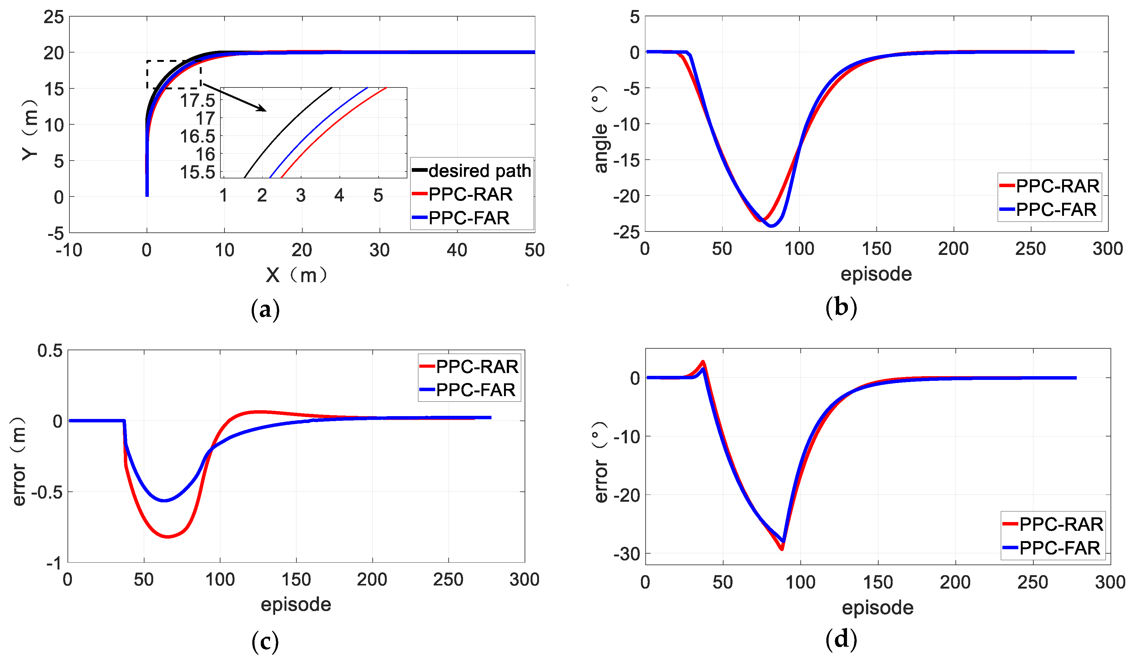
Figure 17 shows the two best experiment results in the curve. The trajectories of the driverless bus are similar for these two controllers. The steering angles are illustrated in Figure 17b. Although the curvature of the path is changed at the connection of a straight arc, the steering angle changes smoothly. Figure 17c,d illustrate the lateral and heading errors. The heading errors are close, but the maximum lateral error of PPC-RAR is larger than PPC-FAR. Thus, the PPC-FAR performs better than PPC-RAR both in lane-keeping and curve-following. Thus, the PPC-FAR is more suitable to driverless buses. Meanwhile, suboptimal l d and k in PPC-FAR are easy to obtain in experiments, which indicate the good adaptability of PPC-FAR.

3.2. Simulation of Longitudinal Control

In this section, an experiment is conducted to verify the efficiency of the longitudinal controller. Since the acceleration is controlled by the VCU on the bus, only deceleration is discussed in this part.
The initial velocity of driverless bus is 40 km/h. The cycle of the controller is 100 ms. The slope of the road is 0. Table 5 shows the parameters of the longitudinal control. Figure 18a shows the simulation scene. Figure 18b shows the designed velocity and simulation results. Meanwhile, Figure 18c indicates the velocity error. Deceleration is shown in Figure 18d. The results illustrate that the system quickly converges to a steady state while there is a deviation and the steady-state deviation is almost 0. The simulation results illustrate the high tracking accuracy of the longitudinal controller. Additionally, deceleration changes continuously and does not exceed −0.6 m/s2. Meanwhile, the velocity of the driverless bus changes constantly, too. Due to the delay of the actuator and the inertia of the driverless bus, there is some slight overshoot in the actual velocity.

4. Real Bus Experiments

A driverless bus system is built in our early work [15]. The global path-planning and local path-planning are available in this implementation. Figure 19a shows the overview of the driverless bus (12 m × 2.57 m × 3.28 m, provided by CRRC ELECTRIC VEHICLE CO., LTD, ZhuZhou City, China). The wheelbase is 5.9 m. As Figure 4 shows, GPS (IMU) is equipped, which gives the position, heading angle, and velocity of the driverless bus. The driverless bus stays in its lane in Figure 19b,c. Additionally, the driverless bus makes a U-turn in Figure 19d,e.
The lane-keeping experiments are carried out to illustrate the advantages of PPC-FAR. The length of the target lane is 2 km, and the curvature is less than 0.01. The initial velocity is 0 km/h, the target velocity is set as 20 km/h. Meanwhile, the initial lateral error is 1.5 m, the initial heading error is close to 0. According to the experiments in Section 3, l d is defined as 15 m, and k is 1. The performances of PPC-FAR and PPC-RAR are shown in Figure 20.
Figure 20a shows the steering angle of PPC-FAR and PPC-RAR. The lateral error is shown in Figure 20b. Obviously, there is almost no error between the actual steering angles and the desired steering angle. Additionally, the steering angles reach −6° to reduce the lateral error in the beginning. The overshoot in PPC-RAR is obvious but there is no overshoot in PPC-FAR. Meanwhile, the lateral error of PPC-FAR is larger than PPC-FAR. The oscillation in PPC-RAR is not obvious in Figure 20, but it is marked if sitting in the bus. When the driverless bus is controlled by PPC-FAR, the bus moves forward smoothly, and the oscillation is hardly felt.
The results of the lane-keeping experiment are similar to the simulation results in Section 3.1.1. Those results show better stability of PPC-FAR under low speed conditions. Meanwhile, the tracking accuracy is also improved.
Another real bus experiment is shown in Figure 21 and Figure 22. There are two straight lanes and a curve which are shown in Figure 21a. The slope of the road is shown in Figure 21b. The first lane is downhill and then there is a curve. The second lane is uphill.
Figure 22a illustrates the desired path and the actual path of the driverless bus. Meanwhile, steering angles and lateral errors are indicated in Figure 22b. During turning, the maximum lateral error is 0.5 m, and the results are similar to the simulation in Section 3. The parameters are instructed in Table 6. k and l d are determined by the fuzzy logic inference machine. Since the model in TruckSim does not describe the real bus well and the real bus requires less time to slow down, the parameters in Table 6 are different from Table 5.
Additionally, the desired velocities and feedback velocities are illustrated in Figure 22c. The initial velocity is 23 km/h, while the velocity reduces to 10 km/h in the turning process. The decelerations and longitudinal errors are illustrated in Figure 22d. Since the feedback of the velocity is discrete and the noise is unpredictable, the longitudinal errors fluctuate. Additionally, the deceleration is continuous and the maximum deceleration is 0.8 m/s2. Conclusively, the experiments in the driverless bus verify the simulation in Section 3 and indicate the good performance of PPC-FAR.

5. Conclusions

A path-tracking controller for a driverless bus is proposed. On this basis, path-tracking is divided into lateral and longitudinal control. Firstly, in lateral control, a path-tracking controller based on FPPC-FAR is indicated. Meanwhile, the reference point of PP is moved from the rear axle to the front axle. It relieves the influence of bus’s lateral dynamic characteristics to path-tracking. Additionally, a fuzzy logic inference machine is adopted to adjust the parameter of PPC-FAR, which improves the tracking accuracy of PPC-FAR. Secondly, in longitudinal control, a feedback-feedforward control algorithm is proposed. In feedback control, TD is introduced to calculate the fast tracking of the desired velocity, which highly improves the input quality of PI. Then, a PI controller is built to track the fast tracking of the desired velocity, which increases the efficiency of longitudinal control. In feedforward control, the component of gravity is applied as the compensation of deceleration, which relieves the influence of the driverless bus’s gravity on longitudinal control. Simulations and real bus experiments indicate the advantages of the path-tracking controller, which is proposed in this paper.
Additionally, the main idea for driverless bus path tracking is only a preliminary work. For making full use of the advantage of those path-tracking algorithms, more accurate driverless bus models should be built in the future. Furthermore, the relationship between the bus performances and the parameters of the path-tracking controller should be clear, too.

Author Contributions

Conceptualization: L.Y.; formal analysis: X.Y.; funding acquisition: L.Y.; methodology: L.Y., X.Y. and Z.K.; resources: Z.K.; software: X.Y. and Z.K.; supervision: B.C. and Y.Z.; validation: X.Y.; visualization: L.Y.; writing—original draft: X.Y. All authors have read and agreed to the published version of the manuscript.

Funding

This work was supported by National Natural Science Foundation of China under grant 61976224 and 61403426, National Key Research and Development Program of China under grant 2018YFB1201602, Major Projects of Science and Technology in Hunan under grant 2017GK1010, and in part by Natural Science Foundation of Hunan under grant 2018JJ2531 and grant 2018JJ2197.

Conflicts of Interest

The authors declare no conflict of interest. The funders had no role in the design of the study, in the collection, analyses, or interpretation of data, in the writing of the manuscript; or in the decision to publish the results.

References

  1. Hugo Neves de Melo, H.N.; Trovão, J.P.F.; Pereirinha, P.G.; Jorge, H.M.; Antunes, C.H. A Controllable Bidirectional Battery Charger for Electric Vehicles with Vehicle-to-Grid Capability. IEEE Trans. Veh. Technol. 2018, 67, 114–123. [Google Scholar] [CrossRef]
  2. Ji, J.; Khajepour, A.; Melek, W.W.; Huang, Y. Path Planning and Tracking for Vehicle Collision Avoidance Based on Model Predictive Control With Multiconstraints. IEEE Trans. Veh. Technol. 2017, 66, 952–964. [Google Scholar] [CrossRef]
  3. Bai, G.; Liu, L.; Meng, Y.; Luo, W.; Gu, Q.; Ma, B. Path Tracking of Mining Vehicles Based on Nonlinear Model Predictive Control. Appl. Sci. 2019, 9, 1372. [Google Scholar] [CrossRef] [Green Version]
  4. Taghavifar, H. Neural Network Autoregressive With Exogenous Input Assisted Multi-Constraint Nonlinear Predictive Control of Autonomous Vehicles. IEEE Trans. Veh. Technol. 2019, 68, 6293–6304. [Google Scholar] [CrossRef]
  5. Guo, H.; Liu, J.; Cao, D.; Chen, H.; Yu, R.; Lv, C. Dual-envelop-oriented moving horizon path tracking control for fully automated vehicles. Mechatronics 2018, 50, 422–433. [Google Scholar] [CrossRef] [Green Version]
  6. Zhang, C.; Hu, J.; Qiu, J.; Yang, W.; Sun, H.; Chen, Q. A Novel Fuzzy Observer-Based Steering Control Approach for Path Tracking in Autonomous Vehicles. IEEE Trans. Fuzzy Syst. 2019, 27, 278–290. [Google Scholar] [CrossRef]
  7. De Jesús Rubio, J. Robust feedback linearization for nonlinear processes control. ISA Trans. 2018, 74, 155–164. [Google Scholar] [CrossRef]
  8. Rubio, J.D.J.; Ochoa, G.; Mujica-Vargas, D.; Garcia, E.; Balcazar, R.; Elias, I.; Cruz, D.R.; Juarez, C.F.; Aguilar, A.; Novoa, J.F. Structure Regulator for the Perturbations Attenuation in a Quadrotor. IEEE Access 2019, 7, 138244–138252. [Google Scholar] [CrossRef]
  9. Tumari, M.Z.M.; Abidin, A.F.Z.; Hussin, M.S.F.; Kadir, A.M.A.; Aras, M.S.M.; Ahmad, M.A. PSO Fine-Tuned Model-Free PID Controller with Derivative Filter for Depth Control of Hovering Autonomous Underwater Vehicle. Methods Mol. Biol. 2019, 3–13. [Google Scholar] [CrossRef]
  10. Soliman, M.A.; Azar, A.T.; Saleh, M.A.; Ammar, H.H. Path Planning Control for 3-Omni Fighting Robot Using PID and Fuzzy Logic Controller. Int. Conf. Adv. Mach. Learn. Technol. Appl. 2019, 921, 442–452. [Google Scholar]
  11. Yin, J.; Zhu, D.; Liao, J.; Zhu, G.; Wang, Y.; Zhang, S. Automatic Steering Control Algorithm Based on Compound Fuzzy PID for Rice Transplanter. Appl. Sci. 2019, 9, 2666. [Google Scholar] [CrossRef] [Green Version]
  12. Kumar, J.; Kumar, V.; Rana, K. Design of robust fractional order fuzzy sliding mode PID controller for two-link robotic manipulator system. J. Intell. Fuzzy Syst. 2018, 35, 1–15. [Google Scholar] [CrossRef]
  13. De Jesús Rubio, J. Hybrid controller with observer for the estimation and rejection of disturbances. ISA Trans. 2016, 65, 445–455. [Google Scholar] [CrossRef] [PubMed]
  14. Jia, L.; Wang, Y.; Zhang, C.; Zhao, K.-H.; Liu, L.; Nguyễn, X. A Robust Adaptive Trajectory Tracking Algorithm Using SMC and Machine Learning for FFSGRs with Actuator Dead Zones. Appl. Sci. 2019, 9, 3837. [Google Scholar] [CrossRef] [Green Version]
  15. Yu, L.; Kong, D.; Shao, X.; Yan, X. A Path Planning and Navigation Control System Design for Driverless Electric Bus. IEEE Access 2018, 6, 53960–53975. [Google Scholar] [CrossRef]
  16. Gonzalez, D.; Perez, J.; Milanes, V.; Nashashibi, F. A Review of Motion Planning Techniques for Automated Vehicles. IEEE Trans. Intell. Transp. Syst. 2016, 17, 1135–1145. [Google Scholar] [CrossRef]
  17. Wu, T. Path tracking control for a robot-trailer system with parameter tuning using particle swarm optimization. In Proceedings of the 2018 IEEE International Conference on Mechatronics and Automation, Changchun, China, 5–8 August 2018. [Google Scholar]
  18. Zhang, B.; Zong, C.; Chen, G.; Zhang, B. Electrical Vehicle Path Tracking Based Model Predictive Control With a Laguerre Function and Exponential Weight. IEEE Access 2019, 7, 17082–17097. [Google Scholar] [CrossRef]
  19. Thrun, S.; Montemerlo, M.; Dahlkamp, H.; Stavens, D.; Aron, A.; Diebel, J.; Fong, P.; Gale, J.; Halpenny, M.; Hoffmann, G.M. Stanley: The Robot That Won the DARPA Grand Challenge. J. Field Robot. 2006, 23, 661–692. [Google Scholar] [CrossRef]
  20. Cui, Q.; Ding, R.; Zhou, B.; Wu, X. Path-tracking of an autonomous vehicle via model predictive control and nonlinear filtering. Proc. Inst. Mech. Eng. Part D J. Automob. Eng. 2017. [Google Scholar] [CrossRef]
  21. Yao, Q.; Tian, Y. A Model Predictive Controller with Longitudinal Speed Compensation for Autonomous Vehicle Path Tracking. Appl. Sci. 2019, 9, 4739. [Google Scholar] [CrossRef] [Green Version]
  22. Challa, V.; Ratnoo, A. Virtual Target based Obstacle Avoiding Guidance. IFAC Pap. 2018, 51, 214–218. [Google Scholar] [CrossRef]
  23. Qiu, W.; Qu, T.; Yu, S.; Guo, H.; Hong, C. Autonomous vehicle longitudinal following control based on model predictive control. In Proceedings of the 2015 34th Control Conference, Hangzhou, China, 28–30 July 2015. [Google Scholar]
  24. Kim, W.; Chang, M.K.; Son, Y.S.; Lee, S.H.; Chung, C.C. Vehicle Path Prediction Using Yaw Acceleration for Adaptive Cruise Control. IEEE Trans. Intell. Transp. Syst. 2018, 19, 3818–3829. [Google Scholar] [CrossRef]
  25. Yao, B.; Yang, J.; Zhang, Q.; Guo, Z.; Hu, R. Research and comparison of automatic control algorithm for unmanned ship. In Proceedings of the 2018 3rd International Conference on Control and Robotics Engineering (ICCRE), Nagoya, Japan, 20–23 April 2018; pp. 85–89. [Google Scholar] [CrossRef]
  26. Li, H.; He, B.; Yin, Q.; Mu, X.; Zhang, J.; Wan, J.; Wang, D.; Shen, Y. Fuzzy Optimized MFAC Based on ADRC in AUV Heading Control. Electronics 2019, 8, 608. [Google Scholar] [CrossRef] [Green Version]
  27. Zhang, H.; Xie, Y.; Xiao, G.; Zhai, C.; Long, Z. A Simple Discrete-Time Tracking Differentiator and Its Application to Speed and Position Detection System for a Maglev Train. IEEE Trans. Control Syst. Technol. 2019, 27, 1728–1734. [Google Scholar] [CrossRef]
  28. Zhang, H.; Xie, Y.; Xiao, G.; Zhai, C. Closed-form solution of discrete-time optimal control and its convergence. IET Control Theory Appl. 2018, 12, 413–418. [Google Scholar] [CrossRef]
Figure 1. The structure of the path-tracking controller.
Applsci 10 00230 g001
Figure 2. Kinematic bicycle model.
Applsci 10 00230 g002
Figure 3. Extended kinematic bicycle model.
Applsci 10 00230 g003
Figure 4. Driverless bus platform.
Applsci 10 00230 g004
Figure 5. The structure of the lateral controller.
Applsci 10 00230 g005
Figure 6. Pure pursuit geometry.
Applsci 10 00230 g006
Figure 7. Pure pursuit control with rear and front axle references.
Applsci 10 00230 g007
Figure 8. Pure pursuit control with a front axle reference.
Applsci 10 00230 g008
Figure 9. Membership functions. (a) Membership functions of v . (b) Membership functions of ρ . (c) Membership functions of l d . (d) Membership functions of k .
Applsci 10 00230 g009
Figure 10. The surface of outputs. (a) The surface of l d . (b) The surface of k .
Applsci 10 00230 g010
Figure 11. The structure of the longitudinal control.
Applsci 10 00230 g011
Figure 12. The fast tracking of the desired velocity.
Applsci 10 00230 g012
Figure 13. High-precision model of AWEB.
Applsci 10 00230 g013
Figure 14. Control performance of PPC-RAR. (a) Desired path and the bus’s path under different conditions. (b) Steering angle. (c) Heading error. (d) Lateral error.
Applsci 10 00230 g014
Figure 15. Performance of PPC-FAR. (a) Desired path and bus’s path under different conditions. (b) Steering angle. (c) Heading error. (d) Lateral error.
Applsci 10 00230 g015aApplsci 10 00230 g015b
Figure 16. Maximum lateral error. (a) Look-ahead distance is 4 m. (b) Look-ahead distance is 6 m.
Applsci 10 00230 g016
Figure 17. The performances of PPC-RAR and PPC-RAR. (a) Desired path and bus’s path under different conditions. (b) Steering angle. (c) Lateral error. (d) Heading error.
Applsci 10 00230 g017
Figure 18. Longitudinal control simulation results. (a) Simulate scene. (b) Desired velocity and actual velocity. (c) Velocity error. (d) Deceleration of the driverless bus.
Applsci 10 00230 g018
Figure 19. Real bus experiments. (a) Overview of the driverless bus. (b,c) Lane-keeping. (df) U-turn.
Applsci 10 00230 g019
Figure 20. Lane-keeping experiment in a real driverless bus with PPC-FAR and PPC-RAR. (a) Steering angle. (b) Lateral error.
Applsci 10 00230 g020
Figure 21. The experiment scene. (a) Desired path. (b) Road slope.
Applsci 10 00230 g021
Figure 22. Results of real driverless bus experiments. (a) Desired path and actual path of bus. (b) Steering angle and lateral error. (c) Desired velocities and feedback velocities. (d) Deceleration and longitudinal error.
Applsci 10 00230 g022
Table 1. Parameters of driverless bus.
SymbolQuantityValueSymbolQuantityValue
mcgBus total mass17,800 (kg)aDistance from center of mass to front axle2.795 (m)
lLength11,950 (mm)bDistance from center of mass to rear axle3.105 (m)
wWidth2540 (mm)IzInertia20,000 (kg m2)
hHeight3350 (mm)CfFront wheel cornering stiffness coefficient6500 (N/rad)
dWheelbase5.9 (m)CrRear wheel cornering stiffness coefficient5200 (N/rad)
Table 2. Rule base of l’d.
sNBNMNSZOPSPMPB
ld
v
NBNBNBNMNSZOPSPS
NMNBNMNSZOZOPSPS
NSNMNSZOZOPSPSPM
ZONMNSNSZOPSPMPM
PSNSNSZOZOPSPMPM
PMNSZOZOPSPMPMPB
PBZOPSPSPSPMPBPB
Table 3. Rule base of k.
sNBNMNSZOPSPMPB
k
v
NBPBPBPBPSZONSNB
NMPBPBPBPSZONSNB
NSPBPBPBPSZONSNB
ZOPBPBPMZONSNMNB
PSPBPBPMZONMNBNB
PMPBPBPMNSNMNBNB
PBPBPBPMNSNMNBNB
Table 4. Performances of PPC-RAR and PPC-FAR with different l d and k .
Algorithmv
(km/h)
ld
(m)
Lateral ErrorFinal StateAlgorithmv
(km/h)
ld
(m)
Lateral ErrorFinal State
PPC-RAR10150.02oscillatePPC-FAR10100stable
200.03oscillate
30150.05oscillate30150.01stable
200.05oscillate200.01stable
60200.06oscillate25250.04oscillate
Table 5. Parameters of longitudinal control for simulation.
ParameterFeedback ControlFeedforward Control
r h k p k i k v
value40.010.190.0010.01
Table 6. Parameters of longitudinal control for real bus experiments.
ParametersFeedback ControlFeedforward Control
r h k P k i k v
value40.010.230.00150.05