Article

Blast-Resistant Performance of Hybrid Fiber-Reinforced Concrete (HFRC) Panels Subjected to Contact Detonation

1
School of Mechanical Engineering, Nanjing University of Science and Technology, Nanjing 210094, China
2
Department of Civil Engineering, Nanjing University of Science and Technology, Nanjing 210094, China
3
State Key Laboratory of Explosion Science and Technology, Beijing Institute of Technology, Beijing 100081, China
4
National Key Laboratory of Transient Physics, Nanjing University of Science and Technology, Nanjing 210094, China
*
Authors to whom correspondence should be addressed.
Appl. Sci. 2020, 10(1), 241; https://doi.org/10.3390/app10010241
Submission received: 30 November 2019 / Revised: 18 December 2019 / Accepted: 23 December 2019 / Published: 28 December 2019
(This article belongs to the Special Issue Fiber-Reinforced Concrete)

Abstract

:

Featured Application

The authors are encouraged to provide a concise description of the specific application or a potential application of the work. This section is not mandatory.

Abstract

This paper experimentally investigates the blast-resistant characteristics of hybrid fiber-reinforced concrete (HFRC) panels by contact detonation tests. The control specimen of plain concrete, polypropylene (PP), polyvinyl alcohol (PVA) and steel fiber-reinforced concrete were prepared and tested for characterization in contrast with PP-Steel HFRC and PVA-Steel HFRC. The sequent contact detonation tests were conducted with panel damage recorded and measured. Damaged HFRC panels were further comparatively analyzed whereby the blast-resistance performance was quantitively assessed via damage coefficient and blast-resistant coefficient. For both PP-Steel and PVA-Steel HFRC, the best blast-resistant performance was achieved at around 1.5% steel + 0.5% PP-fiber hybrid. Finally, the fiber-hybrid effect index was introduced to evaluate the hybrid effect on the explosion-resistance performance of HFRC panels. It revealed that neither PP-fiber or PVA-fiber provide positive hybrid effect on blast-resistant improvement of HFRC panels.

1. Introduction

In recent decades, terrorist attacks on buildings and infrastructure has become a global threat [1,2,3]. To protect civilian lives from possible terrorist attacks, civil infrastructure should provide resistance to extreme loads such as impact and blasts. Ordinary concrete, which is one of the most widely used construction materials, is well-known to be weak under such extreme loadings because of its poor energy absorption capacity and brittle nature [4,5,6]. The addition of fibers is one of the most effective methods to overcome this defect [7,8,9]. The principal benefit of incorporating random evenly distributed fibers into cementitious material is to resist and decay crack propagation [10,11,12]. The fiber contribution to concrete strength begins when concrete micro-cracks initiate and enhance the cracking behavior owing to bridging the cracked sections [13,14,15].
The fibers used for concrete reinforcement are mainly steel fibers, carbon fibers, and polymer fibers [16,17]. Among the polymer fibers, polypropylene (PP) and polyvinyl alcohol (PVA) fibers have attracted most attention due to the outstanding toughness for concrete reinforced with them [18,19]. Concrete is a complex material with multiple phases which include large amounts of C-S-H gel at micron-scale size, sands at millimeter-scale size, and even coarse aggregates at centimeter-scale size. Thus, the properties of FRC will be improved at a certain level, but not whole levels if reinforced with only one type of fiber [20]. For instance, steel fibers are supposed to strengthen concrete at the coarse aggregate scale, while PP or PVA fibers are suitable for the fine aggregate-scale crack prevention, and carbon nanotubes are proven to improve the strength at the scale of cement grains [21]. In practice, hybrid fibers are incorporated in a common cement matrix, and the hybrid fiber-reinforced concrete (HFRC) can offer more attractive engineering properties because the hybrid composite derives benefits from each individual fiber and exhibits a synergetic response [16,22,23,24]. In addition, HFRC shows improved structural behavior compared to conventional concrete, such as less spalling and scabbing under impact loadings [3,25,26,27].
Previously, most of the fiber reinforcement research has been carried out to examine tensile strength [28,29], flexural strength [30,31,32] and drop-weight impact toughness [33,34,35,36]. Only some work dealt with the blast or impact resistance performance affected by fiber content and type [9,37,38], since the extreme loading tests are costly and even dangerous.
Yusof et al. [37] checked the hybrid steel FRC subjected to air-blast loading whereby the hybrid steel fibers may reduce the effect of spalling and scabbing. Lai et al. [39] evaluated the repeated impact resistance of UHPFRC samples including plain straight steel fibers and hybrid steel-PVA and steel-basalt fibers based on the SHPB test machine. It was concluded that the use of hybrid steel-PVA fibers exhibit greater compressive toughness under repeated impacts than steel-basalt fibers. In addition, the hybrid fiber-reinforced UHPC samples exhibited much smaller cracks than the single steel fiber-reinforced UHPC samples because small-sized PVA and basalt fibers were able to effectively control the micro-cracks.
This work, therefore, aims to investigate the blast-resistant performance of hybrid fiber-reinforced concrete against contact detonation. With reference to control specimens, the HFRC panels are assessed for the blast damage level. The damage coefficient and blast-resistant coefficient are then introduced to evaluate the HFRC panel ability against explosion. Finally, the hybrid effect index is introduced to determine the positive or negative roles played by PP and PVA-fiber.

2. HFRC Preparation and Characterization

Prior to the contact detonation tests, a series of material preparation and characterization work is carried out. The concrete mixture and preparation procedure are first explained with the quasi-static tests results analyzed.

2.1. Mix Proportions

Designed with 70 MPa uniaxial compressive strength, the details of the plain concrete mixture proportions in this study are normalized and listed in Table 1. Portland cement (P.I 42.5) was used herein as a cementitious material and fly ash was added as a mineral active fine admixture. Ground fine quartz sand worked as fine aggregate. The water-binder ratio and sand-binder ratio were 0.25 and 0.45, respectively. To improve fluidity, a high-performance water-reducing agent, polycarboxylate superplasticizer (DC-WR2), was also added. In this experimental study, polypropylene, polyvinyl alcohol and steel fibers used for HFRC reinforcement were comparatively depicted in Figure 1. The geometric information and mechanical properties of these three fibers are listed in Table 2. It is suggested that the steel fiber is stronger and stiffer, while the PP-fiber is finer and more flexible and ductile. To investigate the hybridization of PP, PVA and steel fiber (SF) reinforcement effect on HFRC blast resistance, 12 mixtures (Table 3) with a single type or hybrid fiber reinforcement at a total content of 2.0% were produced for sequent experimental studies.

2.2. Concrete Production

The mixing procedure of concrete needs to be rigorously controlled to ensure good workability, particle distribution and compaction, noting that the small particles tend to agglomerate which may break the chunks when the particles are dry. It is suggested to blend all fine dry particles before adding water and superplasticizer. In the climatic chamber with 90% humidity, the concrete samples were prepared with the following mixing procedures. First, the dry cementitious materials (cement, fly ash) and quartz sand were put together simultaneously and mixed for 1 minute at a low speed to achieve the binder–sand mixture. Afterwards, the water and superplasticizer were mixed and gradually poured into the mixture to improve its fluidity. Finally, the fibers were slowly added and mixed for another 5 to 8 min to ensure that all the fibers were evenly distributed in the mortar. 24 h later, the specimens were removed from molds and cured for another 6 and 27 days at room temperature (about 15–25 °C ) with humidity >95%.
It is worth noting that PP and PVA microfibers at 2% volume content negatively affect the fluidity of mixture due to their high specific surface area. Due to the lack of slump-flow test or J-ring test to assess the fluidity of the fresh mixtures, the qualitative evaluation of workability was achieved since the HFRC mixtures exhibit good deformability and proper stability to flow under their own weights. To ensure fluidity, superplasticizer-to-binder ratios were controlled between 0.06% (S1) to 0.5 % (S3). It was observed that HFRC with higher content PP or PVA-fiber exhibited poorer fluidity since more porous microstructure might be yielded due to relatively poor consolidation condition.

2.3. Static Test for Characterization

With the foregoing concrete samples reparation procedure, the quasi-static tests, including uniaxial compression (UC) and 3-point bending, were performed to investigate the effect of fiber reinforcement on the compressive and flexural strength. Since only fine gradation of quartz sand were used as aggregate, we prepare the UC and 3PBT specimens with similar sizes adopted in [40,41]. In this section, the experimental program is explained in detail. Then, experimental results will be reported and discussed based on the average values of tests for 3 specimens. To ensure quasi-static condition, a loading rate of 0.5 mm/min for the load cell of MTS machine was used herein to conduct both UC test and 3PBT.
Specimens of 40 mm × 40 mm × 40 mm were cast for quasi-static compressive strength testing. Three samples of each mix were tested to determine the uniaxial compressive strength. Abrasive paper was used to smooth the surface of the specimens. The non-casting surfaces of the cube specimen were used as bottom and top surfaces of the compression test to ensure complete contact with the plates of the universal testing machine.
To analyze the fiber effect on the flexural strength of FRC, 3-point bending tests were conducted herein with specimens of different fiber mixes. The dimensions of the tested beams are 40 mm (width b) × 40 (depth d) mm in cross-section, and 160 mm in total length where the span l is determined as 120 mm. The beams were supported by a fixed rolling base which provides vertical constraints. The peak load value was then recorded for further study. The nominal flexural strength can expressed as f f = 3 F P l / ( 2 b d 2 ) [36,42], where F P is peak load, l is span length, d denotes the beam depth and b is the beam width.
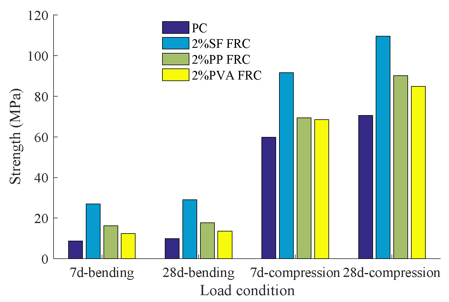
The UC and 3PBT results were plotted in Figure 2 and Figure 3. For 2% hybrid fiber reinforcement, both the 7-d f c and 28-d f c increase as steel fiber content increases. Although PP and PVA fibers are not expected to increase the compressive strength [43], it is observed that polyvinyl alcohol fiber could better improve the compressive strength than polypropylene fiber when the SF content remains constant; meanwhile, the flexural strength can be better improved by PP-fiber incorporation. The post-test beam specimens are shown in Figure 4 where the fibers on the broken surfaces can be clearly observed.
The PVA-Steel and PP-Steel hybrid fiber-reinforced concrete materials are characterized with 0.03 mm smaller-diameter polymer-fiber and 0.22 mm larger-diameter steel fiber. The small-size PP or PVA fibers bridges micro-cracks and therefore controls their coalescence, meanwhile the larger steel fiber tends to arrest the propagation of macro-cracks. Moreover, the steel fiber, which is stronger and stiffer, provides the first crack strength and ultimate strength. It explains why the S4 mix with the more steel fiber content exhibits the highest compressive and flexural strength.

3. Explosion Test Program

The contact detonation test was designed to simulate the bomb explosion scenario (Table 4). A field blast test was carried out on both control concrete samples and HFRC panels to investigate the performance of the concrete panels under contact explosion. After blast tests, a detailed measurement for damaged panels were conducted for further blast-resistance evaluation.

3.1. Contact Detonation Test Setup

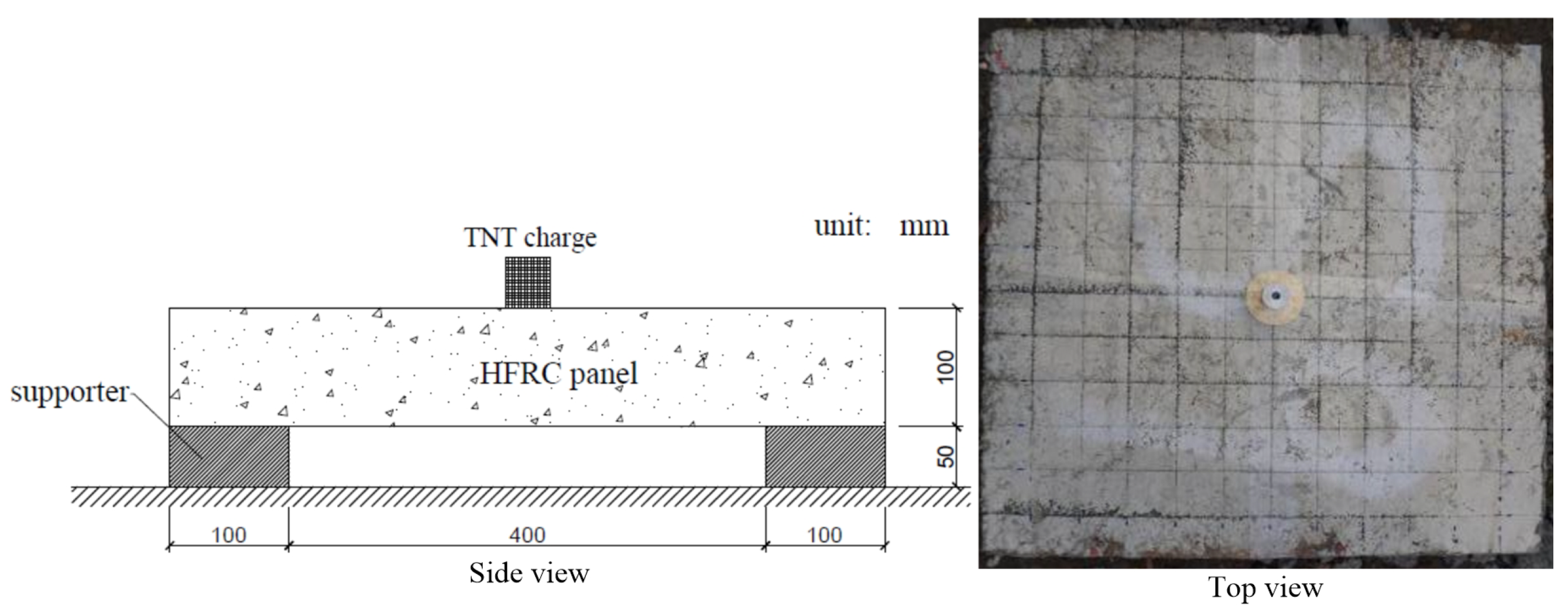
The blast test setup is shown in Figure 5 where the concrete panels were placed on the site at a proper steel frame testing rig providing support along two sides of the specimen. The size of the rig in the plane is 600 mm with 100 mm width and 50 mm height supporters. All concrete panels were tested with 100 g TNT charge cylinder and a height of 44 mm. An electric detonator was applied herein to trigger the explosive charge.

3.2. Damaged HFPC Panels

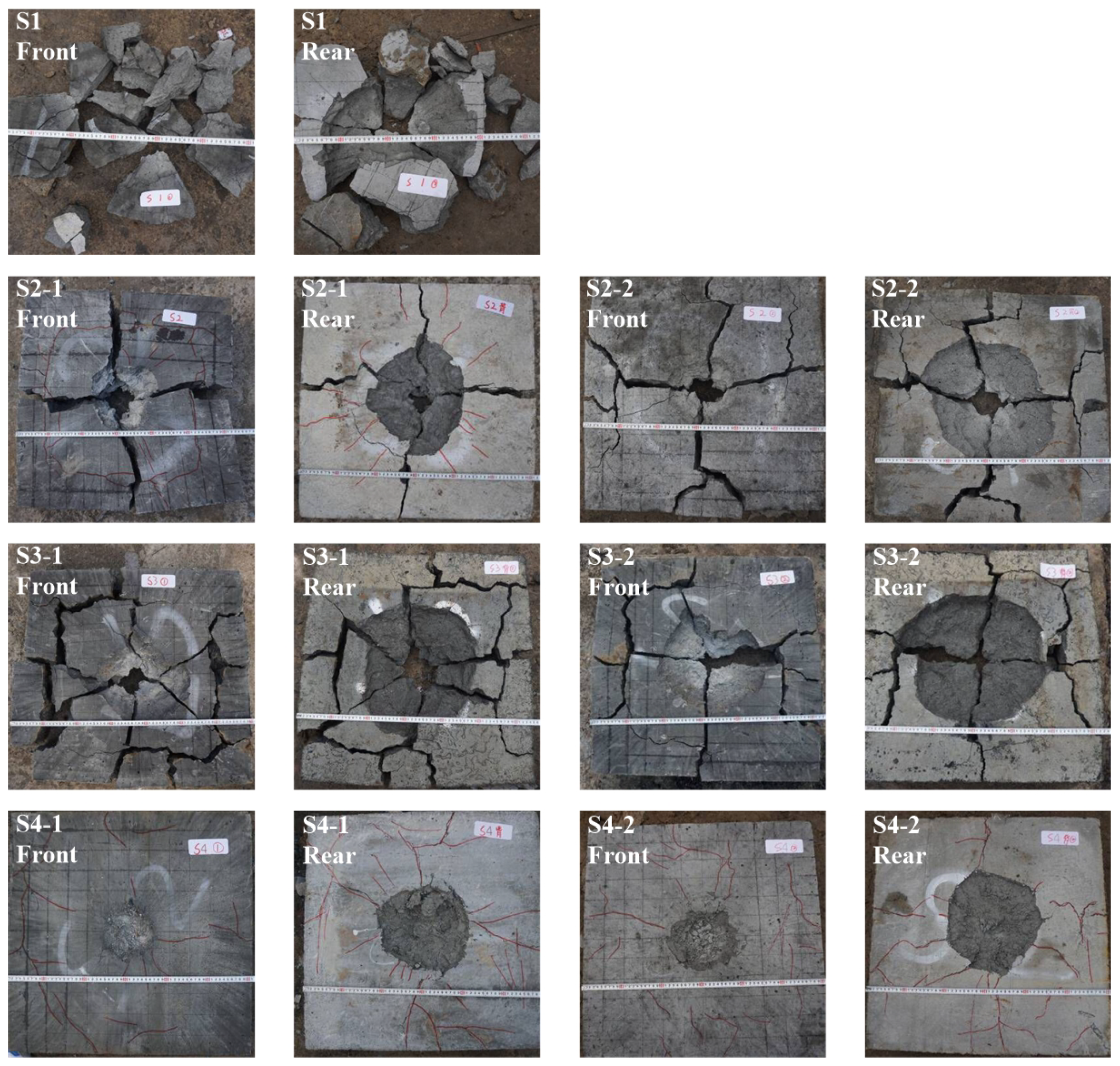
To avoid accidents, each mixture with 2 identical panels were produced for blast tests where the panel numbers were labelled with mixture number plus ‘1’ and ‘2’ as listed in Figure 6, Figure 7, Figure 8, Figure 9 and Figure 10. The crater diameters were measured in both directions parallel to the panel edges. Mix number S1 to S4 were control specimens, while S5 to S8 panels were PP-Steel HFRC and S9 to S12 panels were PVA-Steel HFRC.

3.2.1. Control Specimen

First, the control panels made of plain concrete, PP FRC, PVA FRC and Steel FRC were tested with contact detonation. The fiber reinforcement effect as well as fiber type effects were analyzed.
As depicted in Figure 6, the plain concrete panel was totally torn apart because of the explosion effect. Due to the brittleness, the plain concrete panels could not sustain dynamic loading by contact detonation. By contrast, fiber-reinforced specimen S2 to S4 behaved much better than the plain concrete.
For specimen number S2-1 and S2-2, the front view of the damaged panels showed 4 main broken blocks with 13 and 16 radial cracks. Meanwhile, 19 and 20 radial cracks occurred by the rear view of the damaged panels.
The panel of No. S3-1 was broken into 3 main blocks and 9 smaller pieces, front and rear view showed 28 and 21 cracks. The S3-2 specimen was featured with 4 main blocks and 5 smaller pieces and 19/15 main cracks were observed.
Steel FRC panels had the least damage, with the whole structure remaining intact. Only craters, with rear surface larger, and finer radial cracks, and about 20 cracks on the front and 26 cracks on the rear, occurred.
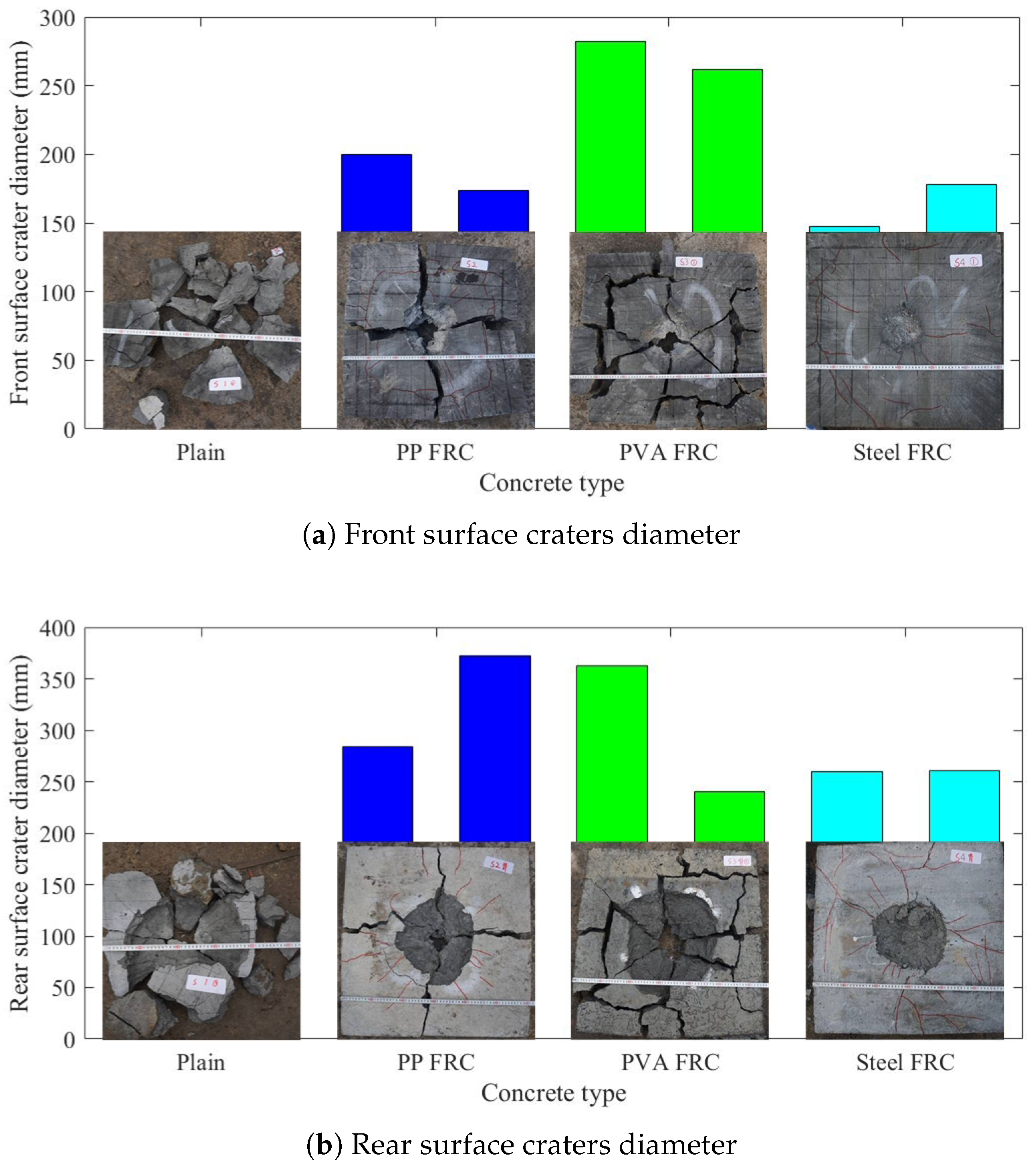
The front crater diameter and depth were plotted in Figure 7a, and the rear crater diameter was shown in Figure 7b. It was clear that plain concrete performed worst in blast resistance, and PP FRC and PVA FRC panels were torn up. The Steel FRC exhibited good resistance against blast loading only leaving small craters on both the front and rear surfaces. It is worth noting the rear crater dimensions were much larger than the front crater. The reason for this phenomenon might lie in the fact that rear surface reflected tensile stress wave causes severer damage to the concrete panel since its tensile behavior is much weaker compared to the compressive property.

3.2.2. PP-Steel HFRC Specimen

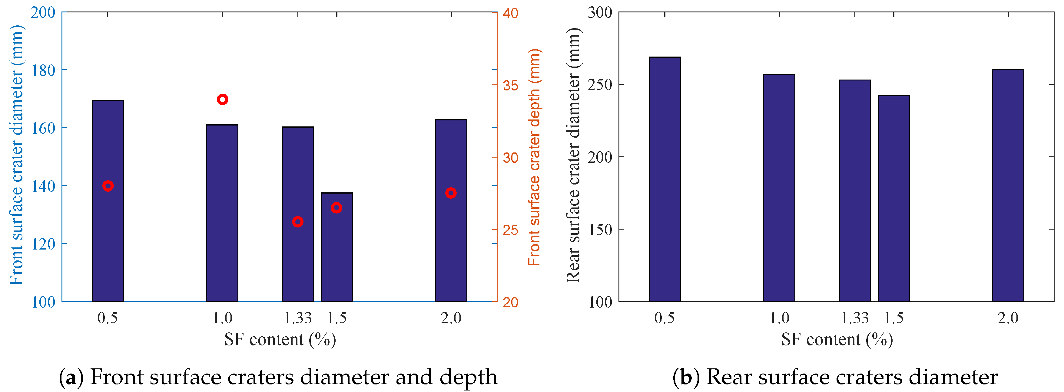
Since only Steel FRC panels could prevent panel structural damage, PP-Steel HFRC specimens were tested against the contact explosion. The post-test results are summarized in Table 5 and Figure 8. Better than PP FRC panels, the PP-Steel HFRC exhibited less server damage, with only craters and fine cracks being observed.
For 0.5% Steel + 1.5% PP HFRC, 17 (front) and 22 (rear) radial cracks were found for S5-1. S5-2 showed 9 and 30 radial cracks for front and rear surfaces.
For 1.0% Steel + 1.0% PP HFRC, constant damage phenomenon was achieved with 12 and 30 radial cracks for front and rear surfaces.
For 1.33% Steel + 0.67% PP HFRC, only 8 (front) and 22 (rear) radial cracks were observed.
For 1.5% Steel + 0.5% PP HFRC, 13 (front) and 26 (rear) radial cracks were found for S8-1 panel. S8-2 panel showed 8 and 29 radial cracks on the front and rear surfaces.
The front crater diameter and depth are plotted in Figure 9a, and the rear crater diameter is shown in Figure 9b. The rear crater dimension was much larger than the front crater. It is interesting to note that the least damage of crater diameter and depth does not coincide with the same fiber hybrid, e.g., 1.33% Steel + 0.67% PP HFRC had the smallest crater depth while 1.5% Steel + 0.5% PP HFRC panel performed best in terms of front and rear crater dimension. However, in general the hybrid fiber mix with 1.5% Steel + 0.5% PP had the least damage.

3.2.3. PVA-Steel HFRC Specimen

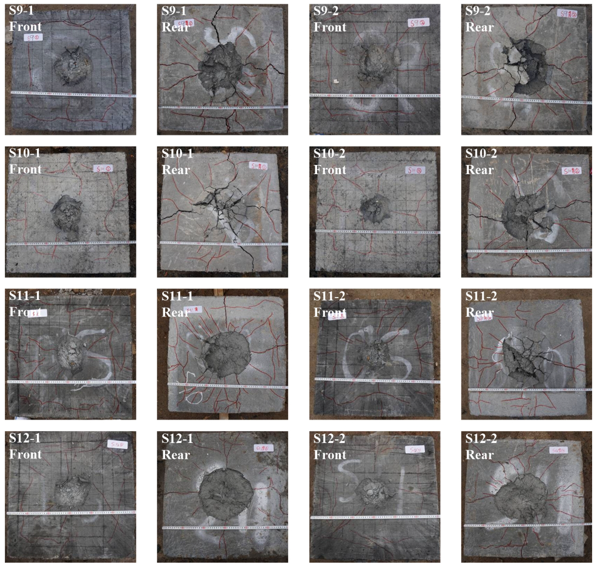
Similarly, PVA-Steel HFRC panel damage is recorded and summarized in Table 6 and Figure 10. The detailed information for S9 to S12 panels was as follows.
For 0.5% Steel + 1.5% PVA HFRC, 5 (front) and 27 (rear) radial cracks were found for S9-1. S9-2 showed 14 and 23 radial cracks for front and rear surfaces.
Panels of 1.0% Steel + 1.0% PVA HFRC had constant damage phenomenon whereby about 8 and 20 radial cracks were recorded on the front and rear surfaces.
Also, panels of 1.33% Steel + 0.67% PVA HFRC were featured with 16 (front) and about 35 (rear) radial cracks.
For 1.5% Steel + 0.5% PVA HFRC, 12 (front) and 19 (rear) radial cracks were found for S12-1 panel. S12-2 panel showed 7 and 28 radial cracks on the front and rear surfaces.
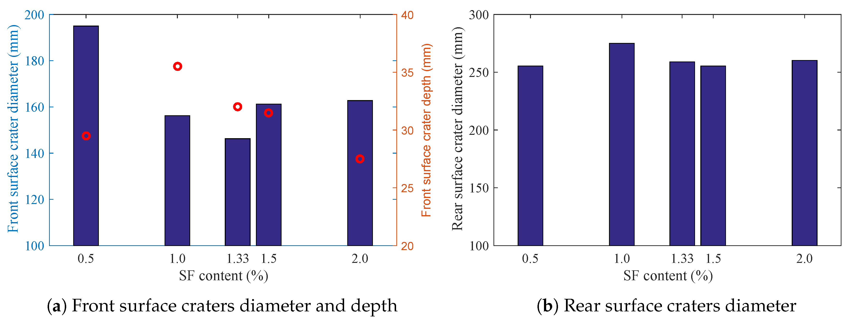
Figure 11a gave the front crater diameter and depth information, and the rear crater diameter is shown in Figure 11b. Also, the least damage of crater diameter and depth does not happen to the same fiber hybrid, e.g., 1.33% Steel + 0.67% PVA HFRC had the smallest front crater diameter while 0.5% Steel + 1.5% PVA HFRC panel had the least front crate depth. In general, it is hard to determine which hybrid fiber mix performed best in terms of blast resistance.

3.3. Blast-Resistance Performance

After explosion tests, the steel fibers were recovered from damaged panels for further scanning electron microscope (SEM) tests. As shown in Figure 12, the steel fiber was magnified by 500, 1000 and 2000 times. The steel fiber pullout in the cement matrix is a non-destructive process since the adhesion is not strong enough.
As pointed out by Zhang et al. [44], the concrete (with reinforcement) panels may exhibit four typical damage modes under detonations. They are cratering, collapse, perforation and punching, as illustrated in Figure 13. The cratering damage is only featured with front surface damage but no scabbing on the rear surface. The collapse damage has both front and rear surface cratering while the panel is not perforated. The more severe damage is perforation, whereby the front crater meets the rear crater. When the detonation shock is fierce enough, the panel may suffer shear plugging where the whole damaged zone is totally punched outward.
For this work with contact detonations, the post-test concrete panels showed two different damage modes, i.e., the plain concrete (No. S1), PP FRC (No. S2) and PVA FRC (No. S3) panels were perforation damaged while the rest were collapse damaged. The Steel FRC together with the PP-Steel HFRC and PVA-Steel HFRC panels were characterized with less damage whereby both front and rear craters occurred but were not perforated yet. To quantitively describe the damage level, damage coefficient K a and blast-resistant coefficient K b were introduced with reference to [44]:
d = K a W ( 1 / 3 )
h = K b W ( 1 / 3 ) 0.5 e
where d is the crater diameter, h is the crater depth, W is the TNT charge weight, and e is the standoff.
With Equations (1) and (2), the damage coefficient K a and blast-resistant coefficient K b were calculated for both PP-Steel and PVA-Steel HFRC, respectively. Since the contact detonation test was performed with 44 mm height TNT, the standoff distance e was estimated as 22 mm.
The results were clearly depicted in Figure 14 for explosion damage level analyses. For both K a and K b , the smaller value reveals better blast-resistant performance. It was demonstrated that HFRC with 1.5% steel + 0.5% PP-fiber goes moderately ahead of 2% steel fiber content concrete. Also 1.33% steel + 0.67% PP HFRC showed similar blast-resistant level than Steel FRC control specimen. Unfortunately, PVA-Steel HFRC had much higher K b than Steel FRC and K a was not improved either. The blast-resistant performance improvement was only achieved by 1.5% steel + 0.5% PP hybrid fiber reinforcement case.
This interesting phenomenon may result from the fact that the relatively flexible PP or PVA-fiber leads to improved toughness and strain capacity in post-cracking response while the steel fiber with high modulus and high tensile strength could effectively increase the strength of concrete. The hybrid mix with 1.5% steel fiber + 0.5% PP or PVA-fiber reveals a synergetic response which significantly increases the concrete strength comparable to S4, and simultaneously improves the ductility. The other mixes used herein are stronger than the control batch S4, thus exhibiting weaker blast resistance.

3.4. Fiber-Hybrid Effect Evaluation

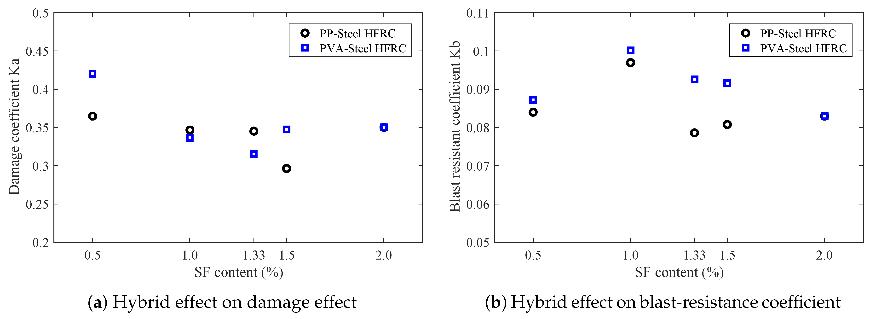
To assess the hybrid effect of PP and PVA-fiber against explosion loadings, Figure 15a compared the damage coefficient K a while Figure 15b depicted the blast-resistant coefficient K b for HFRC with same steel fiber content addition. It was interesting that as steel content raises, the damage coefficient K a for PP-Steel HFRC tends to decrease while K a for PVA-Steel HFRC almost remains constant. The least value for K a occurred around 1.5% Steel + 0.5% polymer (PP or PVA) fiber content. For both PP-Steel and PVA-Steel HFRC panels, the K b exhibited increase and then decrease tendency with increasing steel fiber content.
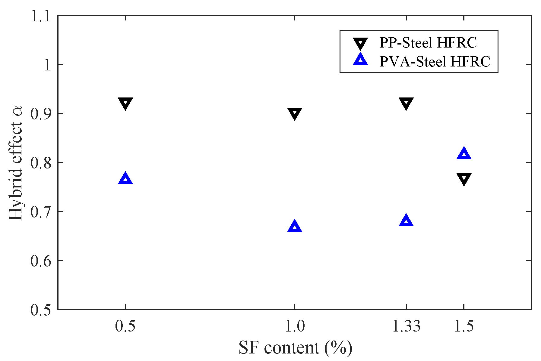
The hybrid effect on the blast resistance of HFRC panels against contact detonation was evaluated by introducing the hybrid effect index α with reference to [24,36]:
α = K H K 0 ( K i K 0 ) β i
where β i = V i / V denotes the fiber volume fraction of one kind fiber in the whole volume of fiber V, V i is the volume of Steel, PP or PVA-fiber, K i is K a or K b of concrete incorporated with single kind fiber, K 0 is K a or K b of control specimen (plain concrete), K H represents K a or K b of HFRC. To exclude the effect of fiber content, the K H calculation should correspond to K i with the same volume fiber reinforcement. This work focused on the 2% content fiber-hybrid effect evaluation. If α > 1 , the fiber-hybrid effect is positive for blast-resistant improvement, otherwise the hybrid effect is negative.
The fiber-hybrid effect evaluation was conducted with Equation (3), and the results for both PP-Steel and PVA-Steel HFRC were plotted in Figure 16. For all the hybrid fiber mixes, the hybrid effect index α < 1, suggesting negative hybrid effect. Nonetheless, PP-fiber had an advantage over PVA-fiber in terms of fiber-hybrid effect on blast-resistance improvement.

4. Conclusions

This work aims to investigate the blast-resistant performance hybrid fiber-reinforced concrete panels. A control specimen with plain concrete, PP-fiber, PVA-fiber and Steel fiber reinforcement were prepared and tested. HFRC specimen with PP + Steel fiber, and PVA + Steel fiber were further analyzed with uniaxial compression, 3-point bending tests and contact detonation tests. The comparative analyses offer conclusions as follows:
(1)
The significant improvement of compressive strength, flexural strength and blast resistance can be achieved by fiber reinforcement. The fiber reinforcement transfers the mechanical responses from brittleness to ductility.
(2)
Steel fiber addition can better improve the compressive strength, flexural strength and blast resistance than PP or PVA-fiber counterparts. The SEM test suggests that the steel fiber tends to pull out from the matrix with few cementitious particles adhering.
(3)
Contact detonation induces both front and rear surface craters. The rear crater dimension tends to be larger than the front crater because of the reflected tensile stress wave, resulting in severer damage on the rear free surface.
(4)
Compared with Steel FRC control specimen, PP-Steel and PVA-Steel HFRC cannot improve blast-resistant performance except for 1.5% steel + 0.5% PP hybrid fiber reinforcement.
(5)
For both PP-Steel and PVA-Steel HFRC, the best blast-resistant performance is achieved at around 1.5% steel + 0.5% polymer-fiber hybrid.
(6)
All the hybrid fiber mixes exhibit negative hybrid effect. PP-fiber has an advantage over PVA-fiber in terms of fiber-hybrid effect on blast-resistance improvement.

Author Contributions

Data curation, Z.S.; visualization, B.C.; Writing—original draft preparation, W.Y. and J.F.; Writing—review and editing, L.C.; supervision, W.S.; funding acquisition, J.F. All authors have read and agreed to the published version of the manuscript.

Funding

This research was funded by the National Natural Science Foundation of China grant number 11602111 and 11902161. The APC was funded by the Natural Science Foundation of Jiangsu Province (No. BK20170824).

Acknowledgments

The SEM experiments were performed at the Materials Characterization Facility of Nanjing University of Science and Technology. Special thanks are given to Haolin Dong, Xudong Gao for their timely helps in conducting detonation tests.

Conflicts of Interest

The authors declare no conflict of interest.

References

  1. Yoo, D.-Y.; Banthia, N. Mechanical and structural behaviors of ultra-high-performance fiber-reinforced concrete subjected to impact and blast. Constr. Build. Mater. 2017, 149, 416–431. [Google Scholar] [CrossRef]
  2. Feng, J.; Sun, W.; Liu, Z.; Cui, C.; Wang, X. An armour-piercing projectile penetration in a double-layered target of ultra-high-performance fiber reinforced concrete and armour steel: Experimental and numerical analyses. Mater. Des. 2016, 102, 131–141. [Google Scholar] [CrossRef]
  3. Wang, Z.; Shi, Z.; Wang, J. On the strength and toughness properties of sfrc under static-dynamic compression. Compos. Part B Eng. 2011, 42, 1285–1290. [Google Scholar] [CrossRef]
  4. Abdallah, S.; Fan, M.; Rees, D.W. Bonding mechanisms and strength of steel fiber–reinforced cementitious composites: Overview. J. Mater. Civ. Eng. 2018, 30, 04018001. [Google Scholar] [CrossRef]
  5. Strieder, E.; Aigner, C.; Petautschnig, G.; Horn, S.; Marcon, M.; Schwenn, M.; Zeman, O.; Castillo, P.; Wan-Wendner, R.; Bergmeister, K. Strengthening of reinforced concrete beams with externally mounted sequentially activated iron-based shape memory alloys. Materials 2019, 12, 345. [Google Scholar] [CrossRef] [Green Version]
  6. Feng, J.; Sun, W.; Wang, X.; Shi, X. Mechanical analyses of hooked fiber pullout performance in ultra-high-performance concrete. Constr. Build. Mater. 2014, 69, 403–410. [Google Scholar] [CrossRef]
  7. Liu, J.; Han, F.; Cui, G.; Zhang, Q.; Lv, J.; Zhang, L.; Yang, Z. Combined effect of coarse aggregate and fiber on tensile behavior of ultra-high performance concrete. Construct. Build. Mater. 2016, 121, 310–318. [Google Scholar] [CrossRef]
  8. Simões, T.; Octávio, C.; Valença, J.; Costa, H.; Costa, D.D.; Júlio, E. Influence of concrete strength and steel fibre geometry on the fibre/matrix interface. Compos. Part B Eng. 2017, 122, 156–164. [Google Scholar] [CrossRef] [Green Version]
  9. Li, P.; Brouwers, H.; Yu, Q. Influence of key design parameters of ultra-high performance fibre reinforced concrete on in-service bullet resistance. Int. J. Impact Eng. 2020, 136, 103434. [Google Scholar] [CrossRef]
  10. Zhang, W.; Chen, S.; Zhang, N.; Zhou, Y. Low-velocity flexural impact response of steel fiber reinforced concrete subjected to freeze–thaw cycles in nacl solution. Constr. Build. Mater. 2015, 101, 522–526. [Google Scholar] [CrossRef]
  11. Hong, K.; Lee, S.; Han, S.; Yeon, Y. Evaluation of fe-based shape memory alloy (fe-sma) as strengthening material for reinforced concrete structures. Appl. Sci. 2018, 8, 730. [Google Scholar] [CrossRef] [Green Version]
  12. Picazo, Á.; Alberti, M.G.; Gálvez, J.C.; Enfedaque, A.; Vega, A.C. The size effect on flexural fracture of polyolefin fibre-reinforced concrete. Appl. Sci. 2019, 9, 1762. [Google Scholar] [CrossRef] [Green Version]
  13. Liu, J.; Wu, C.; Su, Y.; Li, J.; Shao, R.; Chen, G.; Liu, Z. Experimental and numerical studies of ultra-high performance concrete targets against high-velocity projectile impacts. Eng. Struct. 2018, 173, 166–179. [Google Scholar] [CrossRef]
  14. Shaikh, F.U.A.; Luhar, S.; Arel, H.S.; Luhar, I. Performance evaluation of ultrahigh performance fibre reinforced concrete—A review. Constr. Build. Mater. 2020, 232, 117152. [Google Scholar] [CrossRef]
  15. Su, H.; Xu, J.; Ren, W. Mechanical properties of ceramic fiber-reinforced concrete under quasi-static and dynamic compression. Mater. Des. 2014, 57, 426–434. [Google Scholar] [CrossRef]
  16. Hsie, M.; Tu, C.; Song, P. Mechanical properties of polypropylene hybrid fiber-reinforced concrete. Mater. Sci. Eng. A 2008, 494, 153–157. [Google Scholar] [CrossRef]
  17. Singh, N.K.; Rai, B. A review of fiber synergy in hybrid fiber reinforced concrete. J. Appl. Eng. Sci. 2018, 8, 41–50. [Google Scholar] [CrossRef] [Green Version]
  18. Ramezanianpour, A.A.; Esmaeili, M.; Ghahari, S.A.; Najafi, M.H. Najafi, Laboratory study on the effect of polypropylene fiber on durability, and physical and mechanical characteristic of concrete for application in sleepers. Constr. Build. Mater. 2013, 44, 411–418. [Google Scholar] [CrossRef]
  19. Ali, M.; Soliman, A.; Nehdi, M. Hybrid-fiber reinforced engineered cementitious composite under tensile and impact loading. Mater. Des. 2017, 117, 139–149. [Google Scholar] [CrossRef]
  20. Yao, W.; Li, J.; Wu, K. Mechanical properties of hybrid fiber-reinforced concrete at low fiber volume fraction. Cem. Concr. Res. 2003, 33, 27–30. [Google Scholar] [CrossRef]
  21. Szelkag, M. Mechano-physical properties and microstructure of carbon nanotube reinforced cement paste after thermal load. Nanomaterials 2017, 7, 267. [Google Scholar] [CrossRef] [PubMed] [Green Version]
  22. Sivakumar, A.; Santhanam, M. Mechanical properties of high strength concrete reinforced with metallic and non-metallic fibres. Cem. Concr. Compos. 2007, 29, 603–608. [Google Scholar] [CrossRef]
  23. Ding, Y.; Li, D.; Zhang, Y.; Azevedo, C. Experimental investigation on the composite effect of steel rebars and macro fibers on the impact behavior of high performance self-compacting concrete. Constr. Build. Mater. 2017, 136, 495–505. [Google Scholar] [CrossRef] [Green Version]
  24. Song, W.; Yin, J. Hybrid effect evaluation of steel fiber and carbon fiber on the performance of the fiber reinforced concrete. Materials 2016, 9, 704. [Google Scholar] [CrossRef] [Green Version]
  25. Shah, A.A.; Ribakov, Y. Recent trends in steel fibered high-strength concrete. Mater. Des. 2011, 32, 4122–4151. [Google Scholar] [CrossRef]
  26. Su, Y.; Li, J.; Wu, C.; Wu, P.; Tao, M.; Li, X. Mesoscale study of steel fibre-reinforced ultra-high performance concrete under static and dynamic loads. Mater. Des. 2017, 116, 340–351. [Google Scholar] [CrossRef]
  27. Sun, X.; Zhao, K.; Li, Y.; Huang, R.; Ye, Z.; Zhang, Y.; Ma, J. A study of strain-rate effect and fiber reinforcement effect on dynamic behavior of steel fiber-reinforced concrete. Constr. Build. Mater. 2018, 158, 657–669. [Google Scholar] [CrossRef]
  28. Sim, J.; Park, C. Characteristics of basalt fiber as a strengthening material for concrete structures. Compos. Part B Eng. 2005, 36, 504–512. [Google Scholar] [CrossRef]
  29. Martínez-Pérez, I.; Valivonis, J.; Šalna, R.; Cobo-Escamilla, A. Experimental study of flexural behaviour of layered steel fibre reinforced concrete beams. J. Civ. Eng. Manag. 2017, 23, 806–813. [Google Scholar] [CrossRef] [Green Version]
  30. Jin, C.; Buratti, N.; Stacchini, M.; Savoia, M.; Cusatis, G. Lattice discrete particle modeling of fiber reinforced concrete: Experiments and simulations. Eur. J. Mech. A/Solids 2016, 57, 85–107. [Google Scholar] [CrossRef] [Green Version]
  31. Olivito, R.S.; Zuccarello, F.; Zuccarello, A. An experimental study on the tensile strength of steel fiber reinforced concrete. Compos. Part B 2010, 41, 246–255. [Google Scholar] [CrossRef]
  32. Bažant, Z.P.; Rasoolinejad, M.; Dönmez, A.; Luo, W. Dependence of fracture size effect and projectile penetration on fiber content of frc. In IOP Conference Series: Materials Science and Engineering; IOP Publishing: Bristol, UK, 2019; Volume 596, p. 012001. [Google Scholar]
  33. Habel, K.; Gauvreau, P. Response of ultra-high performance fiber reinforced concrete (uhpfrc) to impact and static loading. Cem. Concr. Compos. 2008, 30, 938–946. [Google Scholar] [CrossRef]
  34. Nili, M.; Afroughsabet, V. Combined effect of silica fume and steel fibers on the impact resistance and mechanical properties of concrete. Int. J. Impact Eng. 2010, 37, 879–886. [Google Scholar] [CrossRef] [Green Version]
  35. Nia, A.A.; Hedayatian, M.; Nili, M.; Sabet, V.A. An experimental and numerical study on how steel and polypropylene fibers affect the impact resistance in fiber-reinforced concrete. Int. J. Impact Eng. 2012, 46, 62–73. [Google Scholar]
  36. Feng, J.; Sun, W.; Zhai, H.; Wang, L.; Dong, H.; Wu, Q. Experimental study on hybrid effect evaluation of fiber reinforced concrete subjected to drop weight impacts. Materials 2018, 11, 2563. [Google Scholar] [CrossRef] [Green Version]
  37. Yusof, M.A.; Nor, N.M.; Ismail, A.; Peng, N.C.; Sohaimi, R.M.; Yahya, M.A. Performance of hybrid steel fibers reinforced concrete subjected to air blast loading. Adv. Mater. Sci. Eng. 2013, 2013, 420136. [Google Scholar] [CrossRef] [Green Version]
  38. Feng, J.; Gao, X.; Li, J.; Dong, H.; He, Q.; Liang, J.; Sun, W. Penetration resistance of hybrid-fiber-reinforced high-strength concrete under projectile multi-impact. Constr. Build. Mater. 2019, 202, 341–352. [Google Scholar] [CrossRef]
  39. Lai, J.; Sun, W.; Xu, S.; Yang, C. Dynamic properties of reactive powder concrete subjected to repeated impacts. ACI Mater. J. 2013, 110, 463–472. [Google Scholar]
  40. Banthia, N.; Sheng, J. Fracture toughness of micro-fiber reinforced cement composites. Cem. Concr. Compos. 1996, 18, 251–269. [Google Scholar] [CrossRef]
  41. Sedan, D.; Pagnoux, C.; Smith, A.; Chotard, T. Mechanical properties of hemp fibre reinforced cement: Influence of the fibre/matrix interaction. J. Eur. Ceram. Soc. 2008, 28, 183–192. [Google Scholar] [CrossRef]
  42. Mahmud, G.H.; Yang, Z.; Hassan, A.M.T. Experimental and numerical studies of size effects of ultra high performance steel fibre reinforced concrete (uhpfrc) beams. Constr. Build. Mater. 2013, 48, 1027–1034. [Google Scholar] [CrossRef]
  43. Yap, S.P.; Alengaram, U.J.; Jumaat, M.Z. Jumaat, Enhancement of mechanical properties in polypropylene–and nylon–fibre reinforced oil palm shell concrete. Mater. Des. 2013, 49, 1034–1041. [Google Scholar] [CrossRef]
  44. Zhang, X.; Yang, X.; Chen, Z.; Deng, G. Explosion spalling of reinforced concrete slabs with contact detonations. J. Tsinghua Univ. (Sci. Technol.) 2006, 46, 15–18. [Google Scholar]
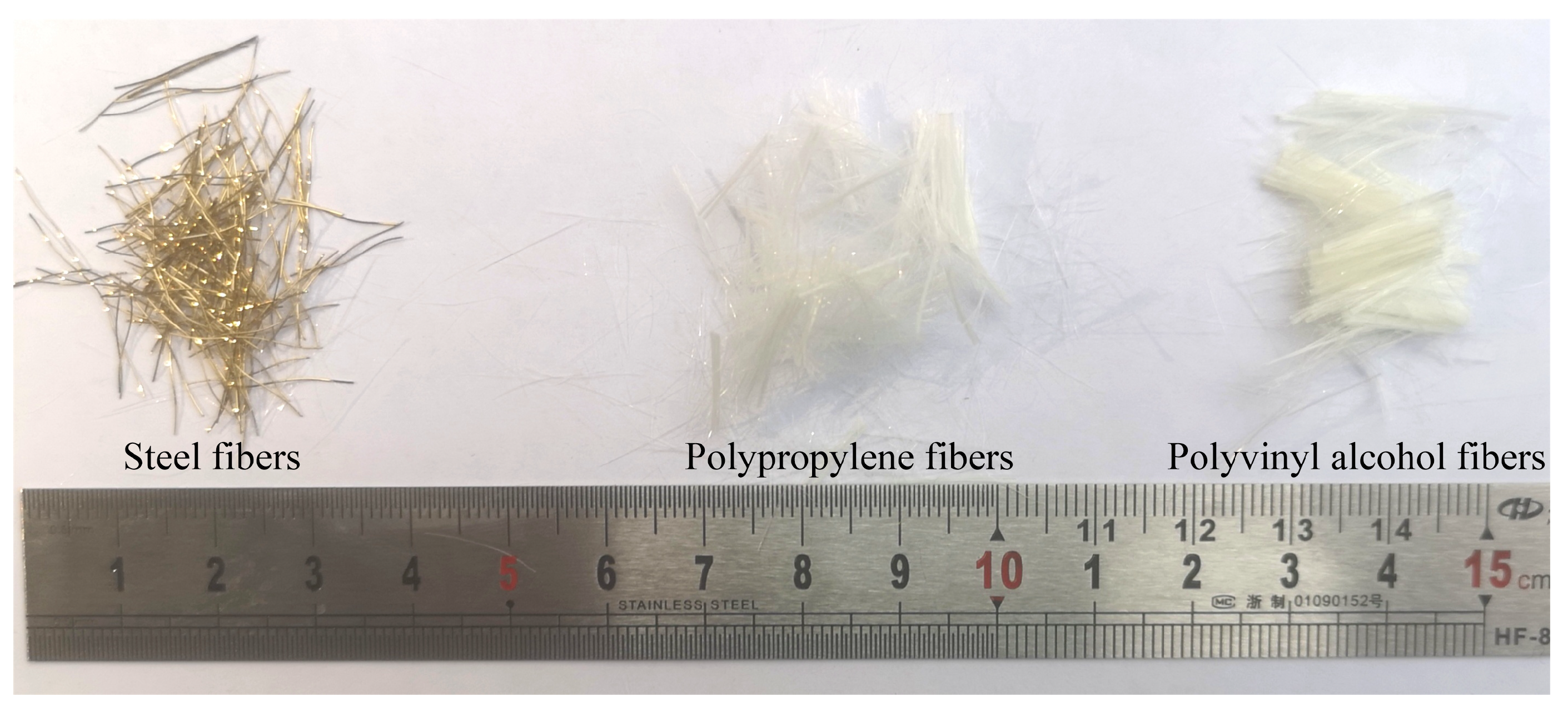
Figure 1. Fibers used for HFRC material cast.
Applsci 10 00241 g001
Figure 2. Fiber reinforcement effect on compressive and flexure strength.
Applsci 10 00241 g002
Figure 3. Hybrid effect on compressive and flexural strength.
Applsci 10 00241 g003
Figure 4. Specimens after 3PBT.
Applsci 10 00241 g004
Figure 5. Detonation test setup.
Applsci 10 00241 g005
Figure 6. Damage mode of concrete panels without/with fiber reinforcement.
Applsci 10 00241 g006
Figure 7. Fiber type effect on panel surface craters.
Applsci 10 00241 g007
Figure 8. Damage mode of PP-Steel HFRC panels.
Applsci 10 00241 g008
Figure 9. Post-blast front and rear surface craters of PP-Steel HFRC panels.
Applsci 10 00241 g009
Figure 10. Damage mode of PVA-Steel HFRC panels.
Applsci 10 00241 g010
Figure 11. Post-blast front and rear surface craters of PVA-Steel HFRC panels.
Applsci 10 00241 g011
Figure 12. SEM images for steel fiber surface after complete pullout.
Applsci 10 00241 g012
Figure 13. Typical damage mode of concrete panels caused by contact explosion [44].
Applsci 10 00241 g013
Figure 14. Damage coefficient K a and blast-resistant coefficient K b .
Applsci 10 00241 g014
Figure 15. Hybrid effect in terms of damage effect and blast-resistance coefficient.
Applsci 10 00241 g015
Figure 16. Fiber-hybrid effect for HFRC.
Applsci 10 00241 g016
Table 1. Mixture for concrete.
ItemCementFly AshWaterQuartz Sand
kg/m31165.9145.7327.9590.2
Table 2. Mechanical properties of fibers.
Fiber TypeDiameter (μm)Length (mm)Density (g/cm3)Tensile Strength (MPa)Elastic Modulus (GPa)
PP 3015–180.912703
PVA 3012–151.3010008
Steel22012–147.851200200
Table 3. Fiber volumetric content for HFRC.
No.Steel FiberPP-FiberPVA-Fiber
S1000
S202%0
S3002%
S42%00
S50.5%1.5%0
S61.0%1.0%0
S71.33%0.67%0
S81.5%0.5%0
S90.5%01.5%
S101.0%01.0%
S111.33%00.67%
S121.5%00.5%
Table 4. Blast damage for plain and fiber-reinforced concrete panels (in mm).
No.Front Crater DiameterFront Crater DepthRear Crater Diameter
S1-1---
S1-2---
S2-1200/200-247/320
S2-2177/170-372/372
S3-1245/320-336/390
S3-2234/289-207/273
S4-1139/15620230/290
S4-2152/20433241/280
Table 5. Blast damage for PP-Steel HFRC panels (in mm).
No.Front Crater DiameterFront Crater DepthRear Crater Diameter
S5-1166/18532249/271
S5-2149/17823265/290
S6-1158/16026280/293
S6-2155/17130203/251
S7-1169/18135224/266
S7-2142/14933247/275
S8-1130/15025240/240
S8-2135/13526214/275
Table 6. Blast damage for PVA-Steel HFRC panels (in mm).
No.Front Crater DiameterFront Crater DepthRear Crater Diameter
S9-1205/20535207/273
S9-2185/18524267/275
S10-1143/14338249/334
S10-2153/18633249/268
S11-1120/17032222/270
S11-2140/15532254/290
S12-1149/18132260/260
S12-2142/17331221/281