Abstract
This paper describes a new method for the detection of moving objects from moving camera image sequences using an inertial measurement unit (IMU) sensor. Motion detection systems with vision sensors have become a global research subject recently. However, detecting moving objects from a moving camera is a difficult task because of egomotion. In the proposed method, the interesting points are extracted by a Harris detector, and the background and foreground are classified by epipolar geometry. In this procedure, an IMU sensor is used to calculate the initial fundamental matrix. After the feature point classification, a transformation matrix is obtained from matching background feature points. Image registration is then applied to the consecutive images, and a difference map is extracted to find the foreground region. Finally, a minimum bounding box is applied to mark the detected moving object. The proposed method is implemented and tested with numerous real-world driving videos, which show that it outperforms the previous work.
1. Introduction
Developing automatic driving assistance systems that can detect driving environments and avoid possible collisions has attracted much interest lately. The rapidly falling costs and increased performance of the sensors involved have contributed to the continuous growth of this field. One of the most critical problems in automatic driving assistance systems is detecting moving objects. The most common approach to moving object detection in this field is using active sensors (e.g., radar, lidar) [1]. However, when a number of vehicles with the same sensors are on the road simultaneously, interference among sensors may cause the system to malfunction. Moreover, active sensors have several drawbacks, such as high computation cost, low spatial resolution, and equipment expense. On the other hand, an optical sensor, which is usually referred to as a passive sensor, is generally cheaper than an active sensor. Moreover, the visual information from optical sensors is very important in various applications, such as traffic sign recognition, object classification, or lane detection. Therefore, motion detection using optical sensors has been studied in various parts of the world.
The optical sensors used in motion detection can be divided into two types, stereo cameras and mono cameras. A stereo camera uses a disparity map to acquire the depth information of the objects viewed. However, a stereo camera works well only if its parameters have been accurately estimated, which is difficult to achieve from a moving vehicle. When a stereo camera is on a quickly moving vehicle, vibrations from the vehicle can disrupt the stability of its parameters and thus finding the correct correspondences for the stereo camera can be a great challenge [2]. Therefore, many existing methods prefer the mono camera approach for detecting moving objects.
One reason that detecting moving objects from image sequences obtained by a moving camera is a difficult task is that the images include the motion of a static background. The motion in the image due to the moving camera is called egomotion. Numerous methods for moving object detection from a moving camera have been studied and proposed.
2. Related Works
Several studies solved the camera movement problem using the spatiotemporal domain of the image sequences [2,3,4,5,6]. Ess et al. proposed a general framework for multiple-object tracking from a mobile vision platform [7], whereas Berrabah studied a robust moving object detection method that uses a Markov random field (MRF) model [8]. Hu et al. proposed a method to use tensor-based image processing for detecting moving objects [9]. Lenac et al. [10] suggested a moving object detection method using dense optical flow generated by moving thermal camera, whereby rotational movement is compensated with the IMU sensor. Yu et al. [11] proposed a method estimating the global motion (egomotion) with grid-based key points by optical flow. An expectation maximization framework was used by Liu et al. to detect the foreground region [12]. Some researchers studied image template matching to find the vehicles or pedestrians in the image [13,14,15,16,17]. Zheng et al. proposed a vehicle detection method using image stripe features [18], and an image registration method was used by Hsieh et al. to detect a vehicle in video sequences [19]. Yazdi and Bouwmans [20] compared various moving object detection methods with a focus on the case of a moving camera. Some studies utilized training techniques to detect objects from video [21,22,23]. Zhang et al. used a structural feature to construct a shape model to detect objects [24]. Some researches proposed a moving object detection method using a Harris interest point detector and optical flow [25,26]. Hu et al. also proposed a method using an epipolar line to classify the feature points of a moving object [27]. However, those methods used features that assumed that the motion of a static background is dominant in the image sequences and that the motion of the camera must be trivial, which is not appropriate for real on-road vehicle situations. Furthermore, the estimated parameters in feature-based methods are not very accurate since the feature points selected for use in parameter estimations are from not only the background but are also from moving object regions. The feature points selected from the moving objects might thus be outliers for the parameter estimation.
The objective of this paper is to develop a new moving object detection method to overcome the shortfalls of the previous studies. Our approach is to use an inertial measurement unit (IMU) sensor to compensate for the movement of the camera and eliminate the outliers in the selected feature points. Figure 1 shows the overview of the proposed moving object detection method.
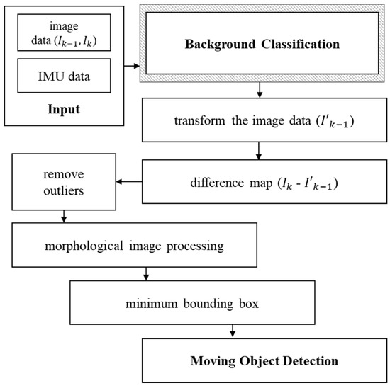
Figure 1.
Overview of the proposed moving object detection method.
The next sections of this paper are organized as follows. Section 3 explains the proposed approach to the background classification, whereas Section 4 describes the details of the overall procedure of the proposed method. Section 5 shows the experiments and results. Finally, this paper is summarized in Section 6.
3. Approach to Background Classification
First, to detect a moving object in the image sequences, a Harris detector, which is mostly used in image registration [28,29], is applied to obtain the interesting points in the image. Next, the correspondences of the feature points in two consecutive images are calculated [30]. In well-known methods, the corresponding feature points can just be used to calculate the transformation matrix of the two consecutive images [31]. However, as mentioned earlier, the feature points of moving objects can be included in the corresponding feature points, and these moving object feature points can adversely affect the accuracy of the transformation matrix calculation. It is difficult to determine whether an individual feature point belongs to a moving object or not.
To determine the criteria for the classification of feature points, a previous work [27] used the distance from the epipolar line to the feature point. Epipolar geometry is commonly used in stereo vision systems to obtain the correspondence of the two images from each camera. However, in the proposed method, epipolar geometry is used in the consecutive images of the moving mono camera. A normalized eight-point algorithm [31] is frequently used to calculate the fundamental matrix with the corresponding feature points of consecutive images. However, the epipolar line might be inaccurate because the correspondences used in the algorithm contain the feature points of the moving object. Therefore, we used both an image sensor and IMU sensor to obtain a more accurate fundamental matrix and epipolar line.
Using IMU data and an image, the initial fundamental matrix of two consecutive images can be calculated. With this fundamental matrix, the epipolar line can be drawn to classify the feature points. In the consecutive images, the corresponding feature points of the background feature must lie on the epipolar line [32]. Therefore, the feature point that is far from the epipolar line can be classified as the foreground point (i.e., the moving object).
Once the feature points are classified for the background and foreground points, the fundamental matrix is calculated from a normalized eight-point method using the background feature points. The epipolar line is then newly drawn without the outliers in the initial classification. This classification process can be applied iteratively until the fundamental matrix converges on a reliable result. In addition, the RANSAC technique [33] is applied to remove the outliers, if any, in the background feature points classification.
The advantage of the proposed classification method is that it can detect moving objects accurately, even in an environment where moving objects are dominating the image, which is different from previous methods. Moreover, any IMU sensor errors are substantially mitigated by the image sensor since the proposed method facilitates the complementary use of the two different sensors. The overview of the proposed background classification method is shown in Figure 2.
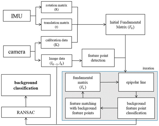
Figure 2.
The proposed background classification method.
4. Proposed Moving Object Detection Method
In this section, the overall process of the proposed method is explained in detail. First, since the two sensors are used simultaneously, we applied an extended Kalman filter [34] to calibrate the IMU sensor and the camera. The two sensors are combined in one platform; the geometric relation between the two sensors is shown in Figure 3. {G} stands for the global coordinate, {I} stands for the IMU coordinate, and {C} stands for the camera coordinate. The movement of global coordinate () is obtained from the IMU sensor, and this can be applied to the image point (P) with the calibration information of the two sensors ().
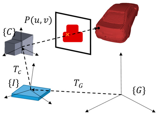
Figure 3.
Geometric relation between camera and IMU (Inertial Measurement Unit) sensor.
In the consecutive image sequences, the feature points are obtained using a Harris corner detector. The pixels with a value above the minimum threshold are considered interesting points. Next, the SIFT descriptor [28] is applied to find the matching relation between the two consecutive images. Many kinds of detectors and descriptors have been studied [35]. The performance of moving object detection varies from changes of these variables. We did several tests to choose these variables, finally deciding on the appropriate parameters that suited our configuration.
An example of feature points and their matching relations is displayed in Figure 4. In the example, the cars are stopped at a red traffic light, except for the taxi on the right which is going to make a right turn.
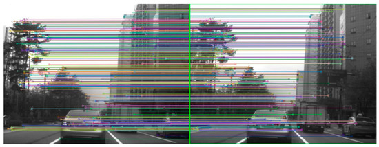
Figure 4.
Feature points and matching relations example.
Using IMU data, the transformation matrix of consecutive images can be calculated. If the movement is smaller than the threshold, the situation is defined as “static camera” case, and the moving feature point is simply classified by the Euclidean distance since there is no egomotion. Otherwise, if the movement exceed the threshold, the situation is defined as “motion camera” case, and the proposed method using epipolar line is applied to classify the feature points.
We use the IMU sensor to calculate the initial fundamental matrix. The fundamental matrix (F) can be calculated in the stereo vision system by the following equation [32].
where R and t are the rotation and translation matrix from the two cameras, and and are the intrinsic parameters of the two cameras. Since in this case the two images are captured with a single camera, the two parameters are the same (.
The rotation and translation data in the consecutive images are obtained from the IMU sensor. If the obtained IMU data is referred as from the frame k and frame k−1, the following equations can calculate the rotation R and translation t of the consecutive images.
The fundamental matrix and feature points are used to draw an epipolar line on the consecutive images. Figure 5 shows the epipolar lines drawn using the IMU sensor on the three example images. The equation below defines a mapping between feature points and epipolar lines.
where and are the feature points from the left and right images. is the right epipolar line, and is the left epipolar line.
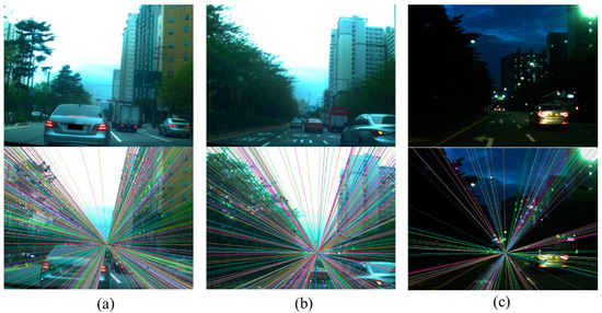
Figure 5.
Epipolar line drawn (lower) on example images (upper). (a) Example image 1; (b) example image 2; (c) example image 3.
If the feature point is moved only by the camera movement, the corresponding feature point of the consecutive image might be placed on the epipolar line. However, if the feature point is the moving object, the feature point may not be on the line. Therefore, the orthogonal distance of the epipolar line and the feature point can be used to classify the moving object. The distance d between the epipolar line and the feature point can be calculated by the following equation
where u and v are the coordinates of the feature point, and a, b, and c represent the coefficient of the epipolar line, .
The feature points of distances that are greater than the threshold are considered to be a moving object. The result of the classification may vary depending on the threshold value setting. In our test configuration, a threshold of 1.0 pixel (in 800 × 600 resolution image) provided the best results in the classification accuracy, which means that the feature points with more than a 1.0 pixel distance from the epipolar line are considered the moving object. Figure 6 shows the feature point classification with the example images. The red points are classified as moving feature points and the white points as background feature points.
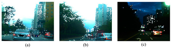
Figure 6.
Feature point classification with example images. (a) Example image 1; (b) example image 2; (c) example image 3.
To calculate a more precise fundamental matrix, the normalized eight-point algorithm [31] is applied only to the background feature points. Then, a more accurate epipolar line can be newly drawn, and the background classification becomes more accurate. This process removes the outliers (foreground) that are initially classified as background feature points. The whole classification process can be applied iteratively until it converges to minimize the error. In addition, the RANSAC technique [33] is also applied to eliminate the outliers, if any, in the background classified feature points.
After the background classification, the transformation matrix can be obtained from decomposition of the fundamental matrix. The obtained transformation matrix is applied to the image to compensate for the motion of the background in the consecutive images. The difference map of the two consecutive images then shows the foreground region. However, there exist a few outliers which are caused by a small movement in the background, such as trees shaking in the wind, etc. These outliers can be removed by denoising and image erosion. Then, the obtained foreground regions are extracted by morphological image processing [27,30]. Figure 7 shows the example of the morphological image processing.
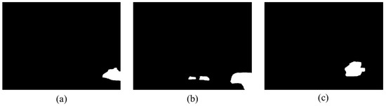
Figure 7.
Extracted foreground region with example images. (a) Example image 1; (b) example image 2; (c) example image 3.
Finally, the minimum bounding boxes are applied to the foreground region to mark the moving object. Figure 8 shows examples of the result. Figure 8a–c shows the result of the proposed method, and Figure 8d–f shows the ground truth for the example images. The proposed method detects the multiple moving objects except for the occluded objects or small (far) objects which has little feature points to detect.
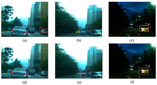
Figure 8.
Bounding box on the example images. (a) Proposed method on example image 1; (b) proposed method on example image 2; (c) proposed method on example image 3; (d) ground truth of example image 1; (e) ground truth of example image 2; (f) ground truth of example image 3.
5. Experiments and Results
The proposed method was implemented in C++ language, and test runs were made on a personal computer with an i7-6500U processor with 8 GB memory and a Windows 10 operating system.
First, we conducted a virtual test to determine the optimal parameters for the proposed background classification algorithm’s variables. The synthetic images were created by the 3ds Max 2017 program developed by Autodesk. A model car was scanned by the commercial scanner REXCAN4® developed by Medit; this 3D model and the road view image texture were applied to the 3DS Max virtual space. Figure 9 shows the synthetic image example we used for the experiment.
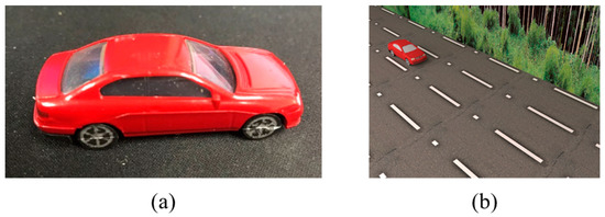
Figure 9.
Virtual test configuration. (a) Scanned model car; (b) synthetic image modeling by 3DS Max.
In the background classification process, several variables can affect the performance of the classification. Since it uses feature point matching, the resolution of the image can affect the matching result. The high resolution image includes the details of the image, while the low resolution image can extract the sharp feature points [30]. Furthermore, the coefficient for the SIFT algorithm can affect the results. If the coefficient (threshold) moves higher, the quantity of the matching points might be small. Otherwise, if the coefficient is lowered, the quantity of the matching points might be large, including the false matching points. The threshold distance between the feature point and the epipolar line can also affect the results. The repeated classification processes can make the classification results more accurate, but a large volume of iterations may cause a high computational cost. These parameters have been optimized from the virtual data test.
One hundred arbitrary synthetic images with 800 × 600 resolution were captured for the test. The camera calibration data and IMU data are obtained easily from the designed synthetic data. The background classification process was applied to each image with differing variables. The feature points were classified manually and used as the ground truth. The average error rates of the experimental results are shown in Figure 10.
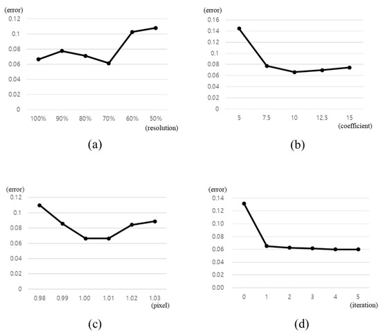
Figure 10.
The result of the synthetic data test. (a) Resolution variation; (b) SIFT coefficient variation; (c) point-line distance threshold variation; (d) classification iteration variation.
The best result was with 70% resolution, 10.0 for the SIFT coefficient and 1.0 pixel for the point-line distance threshold. Three iterations were enough to make the classification error converge to the minimum. We take a simple test with the real-world images comparing these variables, and it shows identical results. Therefore, we used these parameters in the next experiment with real-world images.
There are also interesting results in the angle difference of the moving object direction and the moving camera direction. The angle of camera’s moving direction and the object’s moving direction affects the convergence speed of the algorithm. If the camera and the object are moving in the same direction, the iteration number to the convergence becomes larger. This is because the motion of the feature points on the object pretends to be the background motion caused by the egomotion. On the other hand, if the camera and the object are moving to the different direction, the convergence speed gets faster. This is because the feature point motion is amplified to be easily recognized. The tested result of convergence iteration affected by the moving direction difference is shown in Figure 11.
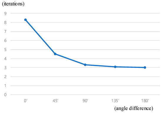
Figure 11.
Iterations required for the convergence affected by the direction difference of moving object and camera.
For the real-world experiment, we used the commercial industrial camera uEye CP developed by IDS and the IMU sensor LPMS-B2 developed by LP-Research. We designed and 3D printed a frame to assemble the two sensors in a fixed position. The configuration of the experiment equipment is shown in Figure 12.
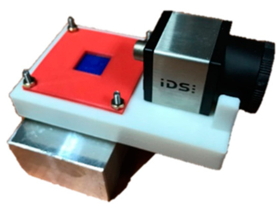
Figure 12.
Experiment equipment assembled with the sensors.
We obtained the data from driving on a road in Seoul, South Korea, for about 1 h, including during the day and night. Since the image processing algorithms have difficulties with diverse light sources and different intensity problems at night, the data sets were divided to compare the performances between day and night. Consequently, we divided the collected data into 10 sets, of which five were collected during the day and five were collected during the night. Each data set had 100 images, and the 1000 images were tested with the proposed method. The feature points were classified manually to be used as the ground truth. In addition, we tested the previous method [27] that uses only the image to compare its results with the proposed method. The classification errors of the two methods are shown in Figure 13.
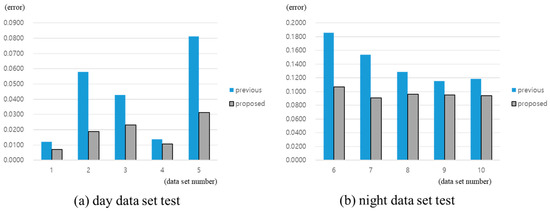
Figure 13.
The results of the real-world data test: (a) Day data set test; (b) night data set test.
The results show that the proposed method is improved in classification accuracy over the previous work. The proposed method shows 98.19% accuracy in the day data set, better than the previous work’s 95.85%. Moreover, the accuracy of the proposed method for the night data set is 90.33%, compared to the previous work’s 85.93%. Table 1 shows the average error rates of the tested algorithms for each data set.

Table 1.
Average error rates of the tested algorithms.
6. Summary
In this research, a new background classification method using an IMU sensor in video image sequences is proposed. One of the major attributes of the proposed method is that it improves the accuracy of feature-based object detection, which has weaknesses in deciphering the images of large foreground regions. To calculate an accurate fundamental matrix, we used the IMU sensor to obtain the initial fundamental matrix. Since the proposed method uses an IMU sensor, it is invariant to the foreground portion of the image. After the initial classification of feature points, the background points are used to calculate a more precise fundamental matrix. This process can be repeated iteratively until it converges to minimize the error. Next, the classified background feature points are used to calculate the transformation matrix of the consecutive images. This transformation matrix is applied to compensate for the movement of the background image. Then, the difference map of the two consecutive images is obtained, and the foreground region is extracted by morphological image processing. Finally, a minimum bounding box is used to mark the moving object.
The proposed method was implemented and was compared with the previous method. Experimentation shows that the proposed approach provides better classification results and is more robust compared to the previous method, even in difficult conditions, including the night. However, the proposed algorithm also has some weaknesses that must be improved. The proposed method has not fully resolved the basic problem of image matching for non-rigid movement. The camera movement and the moving object change the intensity and feature values of the consecutive images. Numerous studies have tried to overcome this limitation using various methods, including machine learning. Further additional research shall be carried out to improve the proposed method.
Author Contributions
Conceptualization, S.J. and M.C.; methodology, S.J.; software, S.J., Y.C., and D.K.; validation, S.J., and D.K.; formal analysis, S.J., and Y.C.; investigation, S.J.; data curation, D.K.; writing—original draft preparation, S.J.; writing—review and editing, S.J.; supervision, M.C. All authors have read and agreed to the published version of the manuscript.
Funding
This research received no external funding.
Conflicts of Interest
The authors declare no conflict of interest. The funders had no role in the design of the study; in the collection, analyses, or interpretation of data; in the writing of the manuscript, or in the decision to publish the results.
References
- Flórez, S.A.R.; Frémont, V.; Bonnifait, P.; Cherfaoui, V. Multi-modal object detection and localization for high integrity driving assistance. Mach. Vis. Appl. 2014, 25, 583–598. [Google Scholar] [CrossRef]
- Sivaraman, S.; Trivedi, M.M. Looking at vehicles on the road: A survey of vision-based vehicle detection, tracking, and behavior analysis. IEEE Trans. Intell. Transp. Syst. 2013, 14, 1773–1795. [Google Scholar] [CrossRef]
- Wu, S.; Oreifej, O.; Shah, M. Action recognition in videos acquired by a moving camera using motion decomposition of Lagrangian particle trajectories. In Proceedings of the 2011 International Conference on Computer Vision, Barcelona, Spain, 6–13 November 2011; pp. 1419–1426. [Google Scholar]
- Zhou, X.; Yang, C.; Yu, W. Moving object detection by detecting contiguous outliers in the low-rank representation. IEEE Trans. Pattern Anal. Mach. Intell. 2013, 35, 597–610. [Google Scholar] [CrossRef] [PubMed]
- Pan, T.; Fan, K.; Wang, Y. Object-Based Approach for Adaptive Source Coding of Surveillance Video. Appl. Sci. 2019, 9, 2003. [Google Scholar] [CrossRef]
- Zhao, W.L.; Ngo, C.W. Flip-invariant SIFT for copy and object detection. IEEE Trans. Image Process. 2013, 22, 980–991. [Google Scholar] [CrossRef]
- Ess, A.; Schindler, K.; Leibe, B.; van Gool, L. Object detection and tracking for autonomous navigation in dynamic environments. Int. J. Rob. Res. 2010, 29, 1707–1725. [Google Scholar] [CrossRef]
- Berrabah, S.A.; de Cubber, G.; Enescu, V.; Sahli, H. MRF-based foreground detection in image sequences from a moving camera. In Proceedings of the 2006 International Conference on Image Processing (ICIP), Atlanta, GA, USA, 8–11 October 2006; pp. 1125–1128. [Google Scholar]
- Hu, W.; Yang, Y.; Zhang, W.; Xie, Y. Moving Object Detection Using Tensor-Based Low-Rank and Saliently Fused-Sparse Decomposition. IEEE Trans. Image Process. 2017, 26, 724–737. [Google Scholar] [CrossRef]
- Lenac, K.; Maurović, I.; Petrović, I. Moving objects detection using a thermal camera and IMU on a vehicle. In Proceedings of the 2015 International Conference on Electrical Drives and Power Electronics (EDPE), Tatranska Lomnica, Slovakia, 21–23 September 2015; pp. 212–219. [Google Scholar]
- Yu, Y.; Kurnianggoro, L.; Jo, K. Moving object detection for a moving camera based on global motion compensation and adaptive background model. Int. J. Control Autom. Syst. 2019, 17, 1866–1874. [Google Scholar] [CrossRef]
- Liu, Z.; Huang, K.; Tan, T. Foreground object detection using top-down information based on EM framework. IEEE Trans. Image Process. 2012, 21, 4204–4217. [Google Scholar] [CrossRef]
- Sun, Z.; Bebis, G.; Miller, R. On-road vehicle detection: A review. IEEE Trans. Pattern Anal. Mach. Intell. 2006, 28, 694–711. [Google Scholar]
- Leibe, B.; Leonardis, A.; Schiele, B. Robust object detection with interleaved categorization and segmentation. Int. J. Comput. Vis. 2008, 77, 259–289. [Google Scholar] [CrossRef]
- Malisiewicz, T.; Gupta, A.; Efros, A.A. Ensemble of exemplar-SVMs for object detection and beyond. In Proceedings of the 2011 International Conference on Computer Vision (ICCV2011), Washington, DC, USA, 6–13 November 2011; pp. 89–96. [Google Scholar]
- Jazayeri, A.; Cai, H.; Zheng, J.Y.; Tuceryan, M. Vehicle detection and tracking in car video based on motion model. IEEE Trans. Intell. Transp. Syst. 2011, 12, 583–595. [Google Scholar] [CrossRef]
- Feghali, R.; Mitiche, A. Spatiotemporal motion boundary detection and motion boundary velocity estimation for tracking moving objects with a moving camera: A level sets PDEs approach with concurrent camera motion compensation. IEEE Trans. Image Process. 2004, 13, 1473–1490. [Google Scholar] [CrossRef]
- Zheng, W.; Liang, L. Fast car detection using image strip features. In Proceedings of the 2009 IEEE Conference on Computer Vision and Pattern Recognition, Miami, FL, USA, 20–25 June 2009; pp. 2703–2710. [Google Scholar]
- Hsieh, J.W.; Chen, L.C.; Chen, D.Y. Symmetrical SURF and Its applications to vehicle detection and vehicle make and model recognition. IEEE Trans. Intell. Transp. Syst. 2014, 15, 6–20. [Google Scholar] [CrossRef]
- Yazdi, M.; Bouwmans, T. New trends on moving object detection in video images captured by a moving camera: A survey. Comput. Sci. Rev. 2018, 28, 157–177. [Google Scholar] [CrossRef]
- Leung, H.K.; Chen, X.; Yu, C.; Liang, H.; Wu, J.; Chen, Y. A Deep-Learning-Based Vehicle Detection Approach for Insufficient and Nighttime Illumination Conditions. Appl. Sci. 2019, 9, 4769. [Google Scholar] [CrossRef]
- Wu, Y.; Tang, S.; Zhang, S.; Ogai, H. An Enhanced Feature Pyramid Object Detection Network for Autonomous Driving. Appl. Sci. 2019, 9, 4363. [Google Scholar] [CrossRef]
- Wang, E.K.; Li, Y.; Nie, Z.; Yu, J.; Liang, Z.; Zhang, X.; Yiu, S.M. Deep Fusion Feature Based Object Detection Method for High Resolution Optical Remote Sensing Images. Appl. Sci. 2019, 9, 1130. [Google Scholar] [CrossRef]
- Zhang, Y.; Kiselewich, S.J.; Bauson, W.A.; Hammoud, R. Robust moving object detection at distance in the visible spectrum and beyond using a moving camera. In Proceedings of the 2006 Conference on Computer Vision and Pattern Recognition Workshop (CVPRW2006), New York, NY, USA, 17–22 June 2006. [Google Scholar]
- Gil-Jiménez, P.; Gómez-Moreno, H.; López-Sastre, R.J.; Bermejillo-Martín-Romo, A. Estimating the focus of expansion in a video sequence using the trajectories of interest points. Image Vis. Comput. 2016, 50, 14–26. [Google Scholar] [CrossRef]
- Felzenszwalb, P.F.; Society, I.C.; Girshick, R.B.; Member, S.; Mcallester, D.; Ramanan, D. Object Detection with Discriminatively Trained Partbased Models. IEEE Trans. Pattern Anal. Mach. Intell. 2010, 32, 1627–1645. [Google Scholar] [CrossRef]
- Hu, W.C.; Chen, C.H.; Chen, T.Y.; Huang, D.Y.; Wu, Z.C. Moving object detection and tracking from video captured by moving camera. J. Vis. Commun. Image Represent. 2015, 30, 164–180. [Google Scholar] [CrossRef]
- Lowe, D.G. Object recognition from local scale-invariant features. Comput. Vis. 1999, 99, 1150–1157. [Google Scholar]
- Zhang, H.; Bai, X.; Zhou, J.; Cheng, J.; Zhao, H. Object Detection via Structural Feature Selection and Shape Model. IEEE Trans. Image Process. 2013, 22, 4984–4995. [Google Scholar] [CrossRef] [PubMed]
- Jung, S.; Song, S.; Chang, M.; Park, S. Range image registration based on 2D synthetic images. Comput. Aided Des. 2018, 94, 16–27. [Google Scholar] [CrossRef]
- Hartley, R.I. In defense of the eight-point algorithm. IEEE Trans. Pattern Anal. Mach. Intell. 1997, 19, 580–593. [Google Scholar] [CrossRef]
- Hartley, R.; Zisserman, A. Multiple View Geometry in Computer Vision; Cambridge University Press: Cambridge, UK, 2003; ISBN 978-0-521-54051-3. [Google Scholar]
- Fischler, M.A.; Bolles, R.C. Random Sample Consensus: A paradigm for model fitting with applications to image analysis and automated cartography. Comm. ACM 1981, 24, 381–395. [Google Scholar] [CrossRef]
- Mirzaei, F.M.; Roumeliotis, S.I. A Kalman filter-based algorithm for IMU-camera calibration: Observability analysis and performance evaluation. IEEE Trans. Robot. 2008, 24, 1143–1156. [Google Scholar] [CrossRef]
- Zitova, B.; Flusser, J. Image registration methods: A survey. Image Vis. Comput. 2003, 21, 977–1000. [Google Scholar] [CrossRef]


© 2019 by the authors. Licensee MDPI, Basel, Switzerland. This article is an open access article distributed under the terms and conditions of the Creative Commons Attribution (CC BY) license (http://creativecommons.org/licenses/by/4.0/).