Abstract
The use of industrial excess heat in district heating networks is very attractive. The main issue is the transport of the heat from the point of generation to the local distribution network, in a way similar to the structure of electricity transport and distribution networks. Absorption systems have been proposed to transport and distribute waste heat using two absorption stations. In one of them (step-up station), industrial heat at a low temperature is pumped to a higher temperature to facilitate its transport and at the same time increase the temperature difference between the supply and return streams, in this way reducing the hot water mass flow rate circulating through the heat transport network. Heat is then used in a second absorption system (step-down station) to provide heat to a low temperature local district network. In this paper, several absorption system configurations are analyzed for both stations. A detailed thermodynamic analysis of each configuration is performed using selected energy performance indicators to calculate its global performance. The implementation of these kind of systems could enable the use of waste heat to produce heating and cooling for smart communities located a few dozens of kilometers away from industrial sites.
1. Introduction and Objectives
Social concerns about climate change are growing. Since the Copenhagen Climate Conference (1997), several countries began implementing energy policies to reduce global warming gases and air pollution. To help this, efficient use of energy, renewable energy sources, and the recovery of waste energy are key actions to mitigate the effects of the global warming and contribute to the sustainable development of our society.
Due to industrial activities, such as washing, drying, cooling processes, emission of furnace exhaust gases, etc., huge amounts of waste heat are released to the ambient atmosphere [1] in many industrial sectors: Petrochemical plants, oil refineries, municipal waste incinerator plants, cement plants, etc. This waste heat can be classified into three groups depending on its temperature, although there is no consensus on the limits for the temperature ranges: High temperature (>400 °C), medium temperature (100–400 °C), and low temperature (<100 °C) waste heat. The technologies for waste heat recovery vary depending on the temperature level of the waste heat and on its final application. In many cases, industrial plants generate large amounts of waste heat, for example, at temperatures of 60 to 70 °C or lower, that has to be simply rejected to the ambient atmosphere using cooling towers or air coolers. Because this temperature is usually too low to be reused in the same industrial processes or in other cases, the demand for this low temperature heat is too small and not economically feasible to be recovered. Papapetrou et al. [2] is presented an interesting estimation of the industrial waste heat available in different industrial sectors per temperature level and country.
The use of this industrial excess heat in urban district heating networks would be very attractive. Modern smart cities are expected to use the heating and cooling of district networks generated with renewable energies or recovered waste heat, thus avoiding as much as possible the use of gas networks inside cities. With respect to the recovery of waste heat, industrial waste heat sources are usually located far away from urban energy demand users. One of the options to transport heat long distances is to upgrade the heat at a higher temperature and transport it at larger distances in a similar way as what is done with electricity, increasing, in that case, its voltage to transport it. However, the typical urban end user does not require heat at a high temperature. Thus, at the user connection substation, the temperature could be reduced accordingly. Another desirable characteristic of the heat transport network is a high temperature difference between the supply and return temperatures of the heat transport network in order to reduce as much as possible the required mass flow rate circulation.
Absorption technologies are heat-driven systems and excellent candidates to perform the two mentioned tasks as follows:
- (1)
- Upgrade low or medium temperature industrial waste heat to a higher temperature in order to be later transported through a network.
- (2)
- Use the transported heat at high temperatures to deliver heat efficiently to a low temperature district heating network while at the same time increase the temperature difference between the supply and return temperatures of the heat transport circuit.
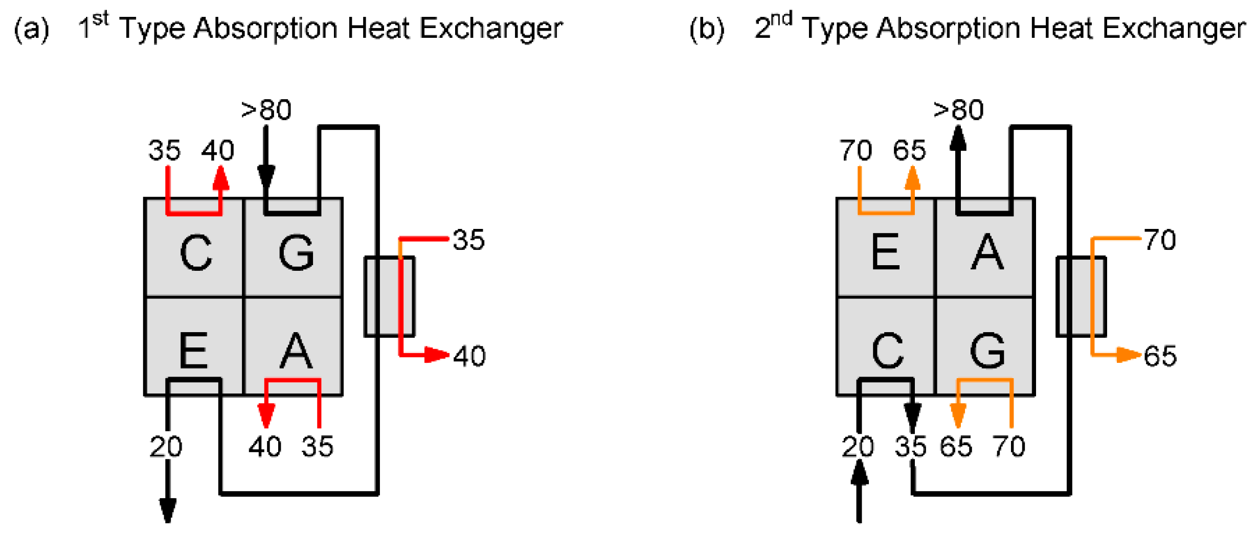
Next, both the characteristics of absorption systems and thermal energy networks are briefly reviewed. The concept and working principles of absorption systems and technologies, including chillers, heat pumps, and heat transformers, are assumed to be known by the interested reader and are already very well covered in the literature [3]. Only the most relevant absorption systems for the heat transport and distribution problem will be covered in detail here. Li et al. [4] introduced the concept of “absorption heat exchanger” (AHE) that consists of an absorption heat pump (AHP) combined with a water-to-water heat exchanger. This configuration is very useful to use heat at high temperatures from the heat transport network and provide heat to low temperature distribution networks. This absorption system provides a temperature drop much higher than that obtained with a conventional heat exchange [4]. Therefore, heat is used more effectively. An AHE consists of an absorption heat pump and a heat exchanger connected as shown in Figure 1a. This type of system has been referred to in the literature as “first type AHE”. The external thermal energy at high temperatures (>80 °C) drives the absorption system and later is used to provide useful heat at a lower temperature (40 °C). After leaving the heat exchanger, its temperature is further reduced at the evaporator before leaving the system. In this way, a much lower return temperature is achieved compared with a simple heat exchanger. The heat rejected at the condenser and absorber is used to provide additional useful heating (Figure 1).
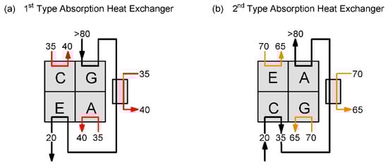
Figure 1.
Example diagram of an “absorption heat exchanger” (AHE) known as (a) first type AHE and as (b) second type AHE, both introduced by Xie and Jiang [6].
Some applications for this AHE have already been analyzed in the literature. Sun et al. [5] reviewed the potential use of industrial waste heat in DHC networks and developed a DH system with a combined heat and power (CHP) with waste heat recovery. Absorption systems are considered to increase the heating capacity of the CHP system by recovering waste heat and using it locally in a DHC network. Xie and Jiang [6,7,8] developed a system for long distance heat transportation based on AHEs. The authors defined two types of AHE: First type and second type, as mentioned above. The first type is an AHE identical as described in the references above (Figure 1a) and it is located near the end users. These step-down thermal substations receive high temperature water from a so-called “second type AHE” that consists of an “absorption heat transformer” (AHT) combined with a conventional heat exchanger (Figure 1b) and is located at the industry plant side (waste heat source). The aim of this second type AHE is to upgrade the temperature of the return hot water of the district heating network (20 °C) up to a temperature (85 °C) higher than that of the input waste heat (70 °C). This configuration increases the hot water temperature difference between the supply and return with respect to conventional DH networks. To achieve the desired performance, large temperature differences between the input and output streams of the cycle components are desirable. Thus, conventional heat pumps cannot be used as AHE and need to be redesigned. This problem could be solved with multi-section components and a vertical configuration to obtain compactness. One of these small capacity AHE was tested satisfactorily in an office building in the city of Chifeng (China) according to Zhu et al. [9]. The authors claim that this developed system is able to replace plate heat exchangers in building substations. In all the mentioned projects, simple absorption systems are considered only to produce heating.
Sun et al. [10] presented a model and an experimental study of an AHE with a heat exchange capacity of 6 MW. Also, they highlighted the advantages of AHE over a typical plate heat exchanger (PHE): The heating capacity of the heating system is enlarged without changing the flow rate due to a lower return water temperature of the primary side of the DH system with respect to the case using a PHE. The concept of AHE has been used not only to efficiently recover waste heat but proposed also to be used in DH networks in combination with natural gas boilers by Sun et al. [11,12].
The concept of cogeneration with absorption heat exchange (Co-ah cycle) is an interesting configuration proposed in the literature, such as in Li et al. [4] and Yang et al. [13]. This concept is similar to that of heat transport proposed by Xie and Jiang [6] but replacing the second type AHE by a steam Rankine cycle and an absorption heat pump. In this Co-ah configuration, the steam extracted from the steam turbine drives the absorption heat pump. The steam at the lowest pressure (condensing stage of the steam turbine) is used as a heat source at the evaporator of the heat pump. Thus, the heat for the DH network is provided both by the condensing stage of the steam plant and the heat rejected at the absorber and condenser of the heat pump.
With respect to the operation of AHEs, the required input and output temperatures of an AHE can change during a given heating period. For this situation, Sun et al. [14] studied the operating conditions to ensure an optimal performance. Xie and Jiang [6] used different indicators defined to analyze the benefits of this kind of absorption system for long distance heat transport. Also, AHEs have been optimized using the so called “entransy” concept to properly measure the irreversibility of the heat transfer processes [15] as an alternative to the exergy method, which is more focused on the measurement of the heat-work conversion.
In summary, the strategy mentioned in the literature above consists on the upgrade of low temperature waste heat (e.g., 60 °C) to a higher temperature (e.g., 90 °C) in order to be transported through a network to a final user or multiple users using a distribution network. An example is given in Xie and Jiang [6], where a real long-distance transport system of 37.8 km is mentioned. At the user side, an AHE will efficiently provide low temperature heat (e.g., 45 °C) and at the same time, producing a high temperature difference between supply and return temperatures in the DH network as additional effect. This configuration is an alternative or complement to the shorter distance low temperature DH networks for smart energy grids (Lund et al. [16]) mainly designed for the distribution of heat instead of its transportation at long distances. The current trend in DHC networks is to reduce their temperature, but in our case, we aimed to introduce absorption systems to effectively recover industrial waste heat at low temperatures. Therefore, the temperature for the transport of heat is set by the driven temperature of the absorption heat pump. Anyway, this temperature is not higher than the current state-of-the-art DHC networks (80–90 °C) and additionally, the studied configurations allows for a reduced mass flow rate circulation with respect to the mentioned conventional DHC networks due to its much lower return temperatures. Thus, the studied system will have a better performance than current state-of-the-art DHC networks, benefiting from the recovery of low temperature industrial waste heat. The purpose of the presented short review is not to provide a full state-of-the-art on district heating and cooling networks, for which there are many reviews in the literature [17,18], but to concentrate on the integration of absorption systems to boost the efficiency and profitability of these networks. A common point of the existing literature is that all efforts are concentrated in the field of heating applications. Only a few references explore the possibility of using a small capacity absorption heat pump to provide heating and cooling depending on the corresponding season (Güido et al. [19]). That paper also addressed the potential of absorption systems to reduce unbalanced heat demand between the winter and summer seasons for district heating networks. However, many buildings suffer simultaneous thermal inversion; therefore, space heating and cooling are both required simultaneously. Another important weak point of previous studies on AHE systems is that usually no details of the absorption system operation are provided, so there is no thermodynamic evidence that the absorption heat pumps can actually work in the required conditions.
The aim of this paper was to perform a detailed analysis of absorption systems to upgrade industrial waste heat to appropriate conditions for its transport at long distances using an absorption heat transformer and use it in distribution district heating networks to supply heat or heat and cooling simultaneously to the connected buildings using an absorption heat pump. Absorption technology plays a key role in this system. In this paper, several absorption system configurations were analyzed for both waste heat upgrading, including single effect and double-absorption heat transformers for the “step-up substation” (SUS) and single effect and double-lift heat pumps to provide heating or heating and cooling (distribution of heat) as a “step-down substation” (SDS). We developed and simulated six complete system configurations using the software Engineering Equation Solver (EES) [20]. A detailed thermodynamic analysis of each configuration was performed, and selected energy performance indicators were used to calculate its global performance for comparison purposes.
In Section 2, the considered global configurations for the proposed transport and distribution networks are presented and a description of the absorption units used as SUS and SDS units. Section 3 shows the details of these configurations, their thermodynamic modelling, and the used performance indicators. Finally, Section 4 and Section 5 present the results and conclusions, respectively.
2. Description of the Heat Transport and Distribution Networks Based on Absorption Systems
2.1. General Description
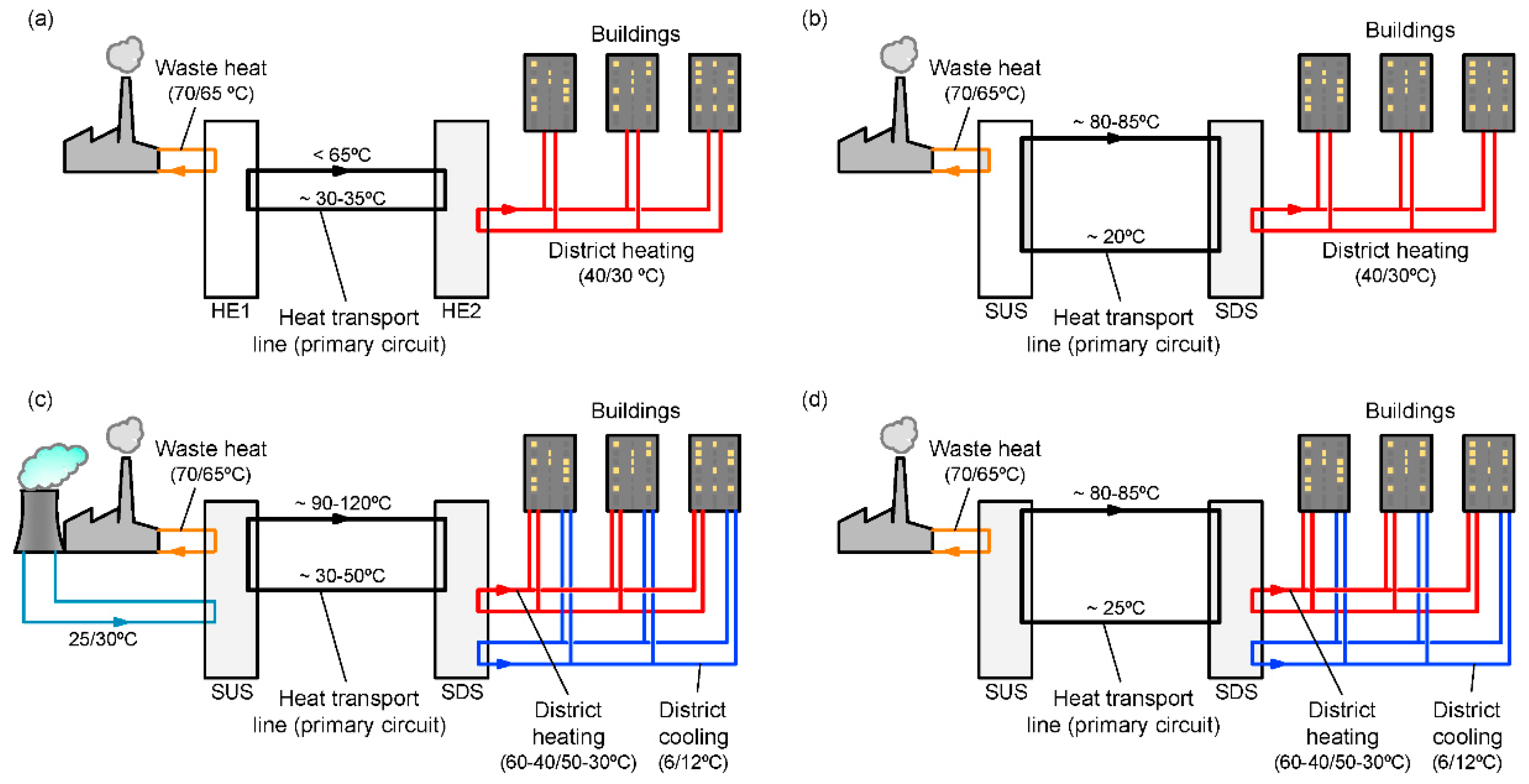
Figure 2 shows the considered configurations to transfer recovered heat from industrial processes to final users. The conventional case (Figure 3a) corresponds to the direct use of waste heat at about 70 °C in a district heating network. In this case, a secondary fluid at about 65 °C transfers the recovered heat to the final users using heat exchanger HE1 and HE2, with a temperature difference between the supply and return of about 30 °C. HE1 and HE2 are simple heat exchangers that are able to provide heat at 40 °C for the buildings connected to the heat distribution network. On the other hand, Figure 2b–d correspond to systems that use absorption technology using two stations, one to upgrade the temperature of the waste heat (SUS) and another one (SDS) to take benefit of this heat to distribute it efficiently to the final users at a lower temperature.

Figure 2.
Configurations for the transport and distribution of waste heat: (a) Conventional system. (b) Absorption-based DH (District Heating) system to supply heat, (c) absorption-based DH and DC (District Cooling) system requiring a cooling tower, and (d) absorption-based DH and DC system without a cooling tower.
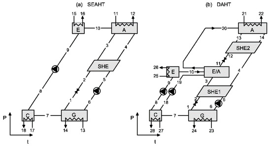
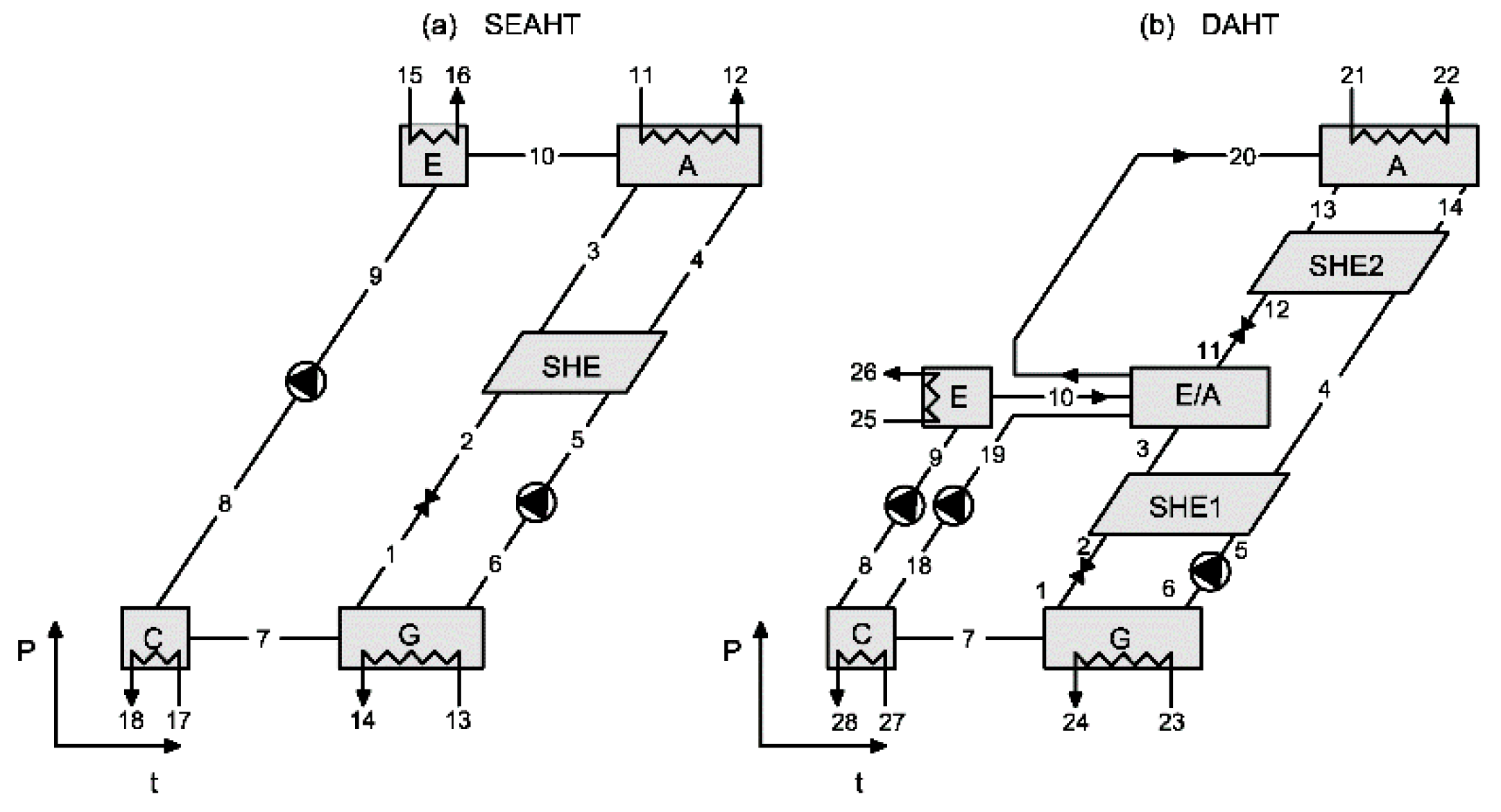
Figure 3.
Dühring scheme of (a) the single-effect absorption heat transformer (SEAHT) and (b) the double absorption heat transformer Type 3 (DAHT).
The working principle of these configurations is similar to that of electricity networks: The waste heat is upgraded at the generation site (industries) in a “step-up thermal station” (SUS) and then the heat is transported to the “step-down thermal substation” (SDS) from which the hot and chilled water are distributed to the end users. Figure 2b shows the case with an absorption heat transformer as SUS unit and an absorption heat pump as SDS to deliver heat, with both using an additional heat exchanger in a similar configuration as presented in Figure 1 and Figure 2. The heat taken at low temperatures at the SDS units reduces the return temperature of the heat transport circuit down to about 20 °C. Figure 2c,d show a similar configuration but using an absorption heat pump able to provide heating and cooling simultaneously. The main difference between Figure 2c,d is the requirement or not of a cooling tower in the step-up thermal station to reject heat to the ambient atmosphere. The elimination of the cooling tower provides many benefits: Lower investment and running costs, avoiding the use of additional chemicals, and lower consumption of water, etc. However, in spite of its disadvantages, the integration of a cooling tower could provide an additional degree of freedom to facilitate the system operation. In the following Section 2.2 and Section 2.3, the absorption units that could be used in the mentioned thermal substations (SUS and SDS) are described in more detail.
2.2. Absorption Heat Transformers (AHT) in Step-Up Thermal Stations (SUS)
The step-up thermal station (SUS) consists of an absorption heat transformer (AHT) coupled with a water-to-water heat exchanger as shown in Figure 1b. The role of the step-up thermal station is to upgrade the temperature of the waste heat. The temperature output of the AHT system is at a higher temperature than that of the waste heat source. In contrast to the conventional waste heat recovery system configuration (Figure 4a), where the temperature of the primary circuit water is lower (65 °C) than that of the waste heat (70 °C). The main performance parameter is the COP defined as the ratio between the heat delivered at the absorber and that supplied at the evaporator and generator. Another fundamental operation parameter for AHTs is the gross temperature lift (GTL) defined as the temperature difference between the upgraded and the waste heat input temperature.
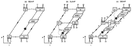
Figure 4.
Scheme in a Dühring chart of (a) the single-effect (SEAHP) absorption heat pump, (b) the double-lift absorption heat pump (DLAHP), and (c) the double-effect absorption heat pump (DEAHP).
There are many papers reviewing the absorption heat transformer technology [21,22] and studying their design and application in many different cases: Production of steam (Hong et al. [23]), integration in a CO2 capture system (Wang et al. [24]), integration with a seawater desalination system (Mahmoudi et al. [25]), etc. This study does not intend to present an exhaustive review on heat transformers but to introduce the most relevant aspects in relation with its application working as an “absorption heat exchanger” in a step-up station. Two of the most studied AHT configurations are considered here: A single-effect AHT (SEAHT) and a double-absorption heat transformer (DAHT) both working with the H2O/LiBr pair, although other pairs have been analyzed in the literature [26] and other configurations, such as the double-lift AHT, are under development [27]. The reason for this choice is that this working pair and the mentioned two AHT configurations are those that offer a contrasted performance for the upgrade of low temperature waste heat at a reasonable performance.
Figure 3a,b show the Dühring scheme of the considered SEAHT and DAHT, respectively. The SEAHT is a tri-thermal absorption system (Figure 3a): High temperature in the absorber, a medium temperature in the evaporator and generator or desorber, and a low temperature at the condenser and working at two pressure levels: High pressure in the absorber and evaporator and low pressure in the condenser/generator. At low pressure, water vapor is driven out of the solution in the desorber (Figure 3a, stream 7) by heating this component, usually with waste heat. The desorbed vapor flows to the condenser, where it changes its phase and heat rejection occurs. The liquid refrigerant is then pumped up to the evaporator at high pressure (stream 8). Waste heat is applied at the evaporator, as was done at the desorber, in this case to produce a liquid-to-vapor phase change (stream 10). The vapor then flows to the absorber, where it recombines with the salt solution coming from the desorber (stream 4) to complete the cycle. The absorption process is accompanied by a thermal energy release that is the output product of this cycle. By transferring energy out at high temperatures (stream 12), the AHT cycle upgrades the temperature of a waste heat stream (streams 13 and 15) to a temperature level at which it is more useful. The pump work requirements are larger than in other absorption heat pumps but usually still low in comparison with the thermal energy input requirements. For favorable applications, single-effect AHT (SEAHT) using water/LiBr offers a COP close to 0.5 and are limited to obtaining a gross temperature lift (GTL) that is usually not higher than 50 °C (Martínez and Rivera [28]).
A double absorption heat transformer (DAHT) is a single-effect absorption heat transformer to which a dual-purpose evaporator/absorber (E/A) unit has been added, as shown in Figure 3b. Different configurations of DAHT have been proposed in the literature regarding the flow path of the solution from the generator to the main absorber. Zhao et al. [29] investigated three of them known as DAHT type 1 (series flow), DAHT type 2 (parallel flow), and DAHT type 3 (a series flow modified where the solution leaving the absorber first goes to a solution heat exchanger before entering the double absorption unit (see Figure 4b). This DAHT configuration (type 3) was proposed by Mostofizadeh and Kulick [30], who designed an experimental facility. The DAHT type 3 cycle has a higher coefficient of performance compared with other types of DAHT, especially when a large temperature lift is required (Zhou et al., 2003) [29]. The maximum GTL for a DAHT type 3 is about 60 to 100 °C, which mainly depends on the corresponding condensing temperature. This GTL is higher than that of an SEAHT, but its COP is clearly lower, usually just a little bit higher than 0.3. This DAHT configuration is also the best according to the conclusions of Ma et al. [31], who modeled four configurations to upgrade waste heat between 40 and 60 °C. Therefore, it is also the one selected in the present work.
2.3. Absorption Heat Pumps (AHP) in Step-Down Thermal Substations (SDSs)
The SDS consists of one or more absorption heat pumps driven by the hot water of the primary or heat transport circuit coupled with a water-to-water heat exchanger, as shown in Figure 1b, with the objective to supply hot and/or chilled water to a local distribution district thermal network. The type of absorption machine used for a given thermal station will depend mainly on (1) the required hot water temperature of the local district heating and (2) the heating and/or cooling demand profiles of the connected end users.
For the SDS, three types of absorption systems working with the working pair H2O/LiBr are analyzed: Single-effect, double-lift, and double-effect absorption chillers. Figure 4 shows the Dühring scheme for these absorption chiller configurations. The single-effect configuration (see Figure 4a) is able to produce both chilled water at the evaporator and hot water at the condenser and absorber but at quite a low temperature.
Another option to produce heating and cooling is a double-lift absorption heat pump (Figure 4b) when driven heat is available at the required temperature. This kind of cycle was already investigated in the past using organic-based working fluids [32] and it is also known in the literature as a heat-coupled half effect cycle [33] or double lift cycle II [34]. This cycle is able to produce hot water at a higher temperature than a single-effect cycle, but at the expense of a lower heating and cooling efficiencies (COP and EER, respectively). The double lift is a three-pressure cycle with two pairs of evaporator-absorbers as shown in Figure 4b. The main benefit of this cycle is the increase in the temperature difference between evaporator E2 and absorber A1. Thus, the output temperature from absorber A1 is higher than the usual temperature in an absorption system. The heat rejected in the absorber A2 is used as input heat for the higher-pressure evaporator, E1. A double-effect cycle (Figure 4c) is another option when the driving temperature available is high to provide cooling at high efficiency, but as in the case of the single effect, the provided heat is at quite a low temperature.
3. System Configurations and Modelling
3.1. SUS and SDS Configurations
The proposed system configurations are intended to recover waste heat at 60 to 70 °C or slightly lower. This temperature level is known to be abundant and in excess in industrial facilities and would not be so easily recovered inside the same industrial process due to its low temperature. In the SUS, a water-to-water heat exchanger is used in combination with the AHT to build an “absorption heat exchanger” in such a way that the inlet return water from the DH network is preheated before it enters the absorber of the AHT to upgrade the water temperature to its final target, as shown in Figure 1b. If the return temperature of the transport circuit is at a temperature that is low enough (Figure 2b,d), it is used as cooling media at the condenser of the AHT. If not, a cooling water tower has to be included as is the case shown in Figure 2c.
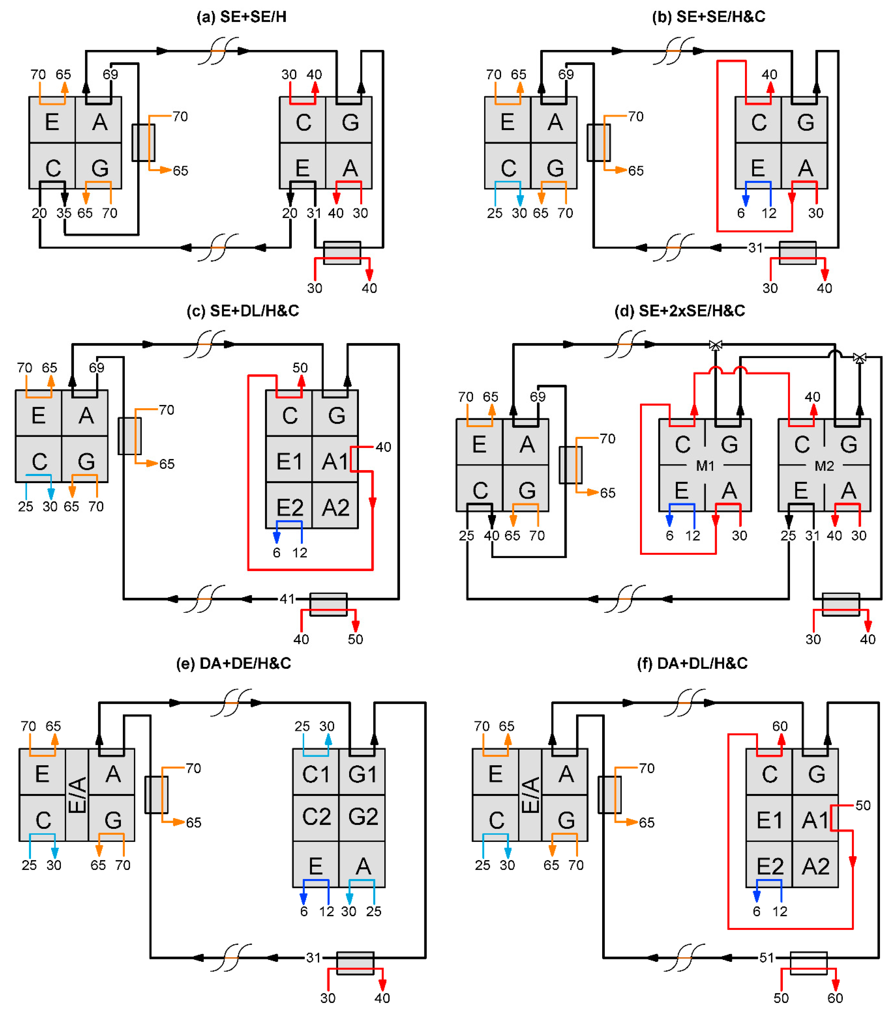
Six system configurations (Figure 5) are studied to recover low-temperature waste heat, upgrade it, transport this heat at a higher temperature, and deliver it efficiently at a lower temperature to the final users. The used nomenclature to name each configuration is: “Absorption unit for SUS” + “absorption unit for SDS”/“H or H&C” depending on only heating or heating and cooling is delivered to the final user. In this figure are shown some typically expected temperatures for each input and output stream. Configurations differ from each other by the type of absorption technology used and by: (1) The temperature of the hot water in the heat transport network, (2) the capability (or not) to produce chilled water to supply cooling using the distribution network, and (3) the need (or not) of a cooling tower in the step-up thermal station and the step-down thermal station.
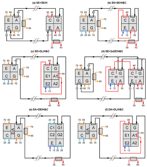
Figure 5.
Analyzed system configurations based on absorption technology to recover low-grade waste heat. (Color lines: Orange—Waste heat, Red—Heat supply, Dark blue—Chilled water, Light blue—Cooling water).
Table 1 summarizes the main features of each configuration shown in Figure 5. Configuration (a) (SE + SE/H) can deliver only heating while all the others can supply heating and cooling. Configuration (a) and (d) do not require the use of a cooling tower. System configurations that produce hot water at 40 to 50 °C are suitable for terminal units, such as fan-coils or a combination of radiant floor and fan-coils [35]. However, the configuration DA + DL/H&C (configuration (f)) produces hot water at 60 °C, so this temperature might be suitable for heat radiators. For those applications requiring temperatures higher than 40 °C, the double lift SDS is required. Except configuration (a), all the others are designed to produce both heating and cooling. Next, each configuration is described in more detail.

Table 1.
System configurations and operating modes.
- SE + SE/H configuration (Figure 5a): This configuration was proposed by Jiang and Xie [6]. It consists of an SEAHT in the step-up thermal station (SUS) and a single-effect absorption machine in the step-down thermal substation (SDS). This configuration is designed to be coupled with a distribution district heating network at 40 °C using the heat released at the absorber and condenser of the SDS. The evaporator of the SDS unit is used to increase the temperature difference of the heat transport circuit and consequently reduce its required flowrate.
- SE + SE/H&C configuration (Figure 5b): It is designed to provide not only heating as in the previous configuration but also cooling. The AHT of the step-up thermal station is a single-effect AHT. Both the absorber and the condenser of the AHP and an additional heat exchanger are used to produce hot water at 40 °C. A single-effect AHP is used in the step-down thermal substation using its evaporator to produce chilled water at 6 °C. Thus, a cooling tower is necessary in the step-up thermal station, because the return temperature could be too high to be used in the condenser of the AHT.
- SE + DL/H&C configuration (Figure 5c): This configuration combines a single-effect AHT at the step-up thermal station with a double-lift AHP at the step-down thermal substation. This system produces hot water for the district network at a higher temperature (50 °C) than configuration (b) SE + SE/H&C (40 °C) for the same driving temperature. The evaporator E1 and absorber A2 are heat coupled as shown in Section 2.3. The evaporator E2 of the double-lift AHP produces chilled water at 6 °C for the DC network. Thus, the return water of the heat transport circuit could not be low enough to be used in the condenser of the AHT. Hence, the use of a cooling tower in the SUS is required.
- SE + 2xSE/H&C configuration (Figure 5d): This configuration is a hybridization between configurations SE + SE/H (a) and SE + SE/H&C (b). At the step-down thermal substation, this configuration uses two single-effect AHP. This system configuration produces chilled water (as in the configuration SE + SE/H&C), but it also removes the cooling tower at the step-up thermal station (as in the configuration SE + SE/H&C). The evaporator of the first single-effect AHP (evaporator E1) is used to produce chilled water at 6 °C for the DC network and the evaporator of the other single-effect AHP is used to cool down the temperature of the return water of the primary circuit. Thus, the cooling tower is removed in this configuration and it simultaneously produces hot water for the DH network at 40 °C.
- DA + DE/H&C configuration (Figure 5e): A double-absorption AHT is used at the step-up thermal station and a double-effect AHP at the thermal station. Since the technology of the heat transformer utilized in this configuration provides hot water for the transport network at a higher temperature, the double effect configuration can take advantage of this fact to increase the efficiency of the cooling production with respect to the single effect or the double lift configuration. This configuration produces hot water at 40 °C, and chilled water at 6 °C. Notice that a cooling tower is required in this case for both the SUS and the SDS. This configuration is similar to SE + SE/H&C (b) but using a double absorption instead of a single-effect heat transformer in the step-up station. The main benefit is the higher temperature available to drive the heat pump of the step-down absorption heat exchanger.
- DA + DL/H&C configuration (Figure 5f): In this case, a double-absorption AHT is also used instead of a single-effect AHT for the step-up station and a double-lift AHP is used in the step-down thermal substation. In this case, the system produces hot water at 60 °C, which is higher than that achieved by the configuration SE + DL/H&C (C) (50 °C) thanks to the double-absorption configuration. Chilled water is sent to the DC network at 6 °C. A cooling tower is required at the step-up thermal station.
3.2. Modelling
The modelling of the single-effect AHT and AHP and double-lift AHP are based on the usual mass and energy balances and assumptions used for the modelling of absorption cycles [3]. On the other hand, the model of the double-absorption AHT is based on the work of Zhao et al. [29]. All models were developed in engineering equation solver (EES) [20].
The general expression for the mass balance in each system component is written as follows:
and the general expression for the energy balance in each component is given by the following expression:
Table 2 summarizes the main modelling assumptions for the temperature and temperature differences between the internal and external streams involved in the main heat exchangers of the absorption machines operating both at the SUS and SDS and for all the configurations presented in Figure 5.
On the other hand, solution heat exchangers are modelled using the effectiveness NTU method. The effectiveness () for the solution heat exchangers is defined as follows:
The common assumptions for all the absorption systems modelled in this work are listed below:
- Simulations were performed under steady-state conditions.
- Heat and pressure losses were not considered.
- The only pressure drop considered was in the throttle valves and assumed as isenthalpic.
- Saturated conditions at the outlet of absorbers, generators, condensers, and evaporators.
- The effectiveness of solution heat-exchangers was 50%.
- The heat transport line was pressurized at 600 kPa.
3.3. Performance Indicators
In this paper, we used some parameters and performance indicators to evaluate the individual performance of the SUS and SDS units in each configuration presented in Figure 5, and also to evaluate the overall performance of the whole configuration (SUS + SDS).
To evaluate and compare the performance of the SUS of each configuration, the following parameters and indicators were used:
- Heat transport line’s supply temperature (Tt,s).
- Temperature lift defined as: .
- High and low internal pressures: ph and pl, respectively.
- Mass flow rates of the waste heat stream (mWH) and water stream in the cooling tower circuit (mCT).
- LiBr concentration difference between stronger and weaker solution streams (Δx).
- Coefficient of performance of the absorption heat transformer: .
To evaluate and compare the performance of the absorption heat pumps installed at the SDS, we used the following parameters and indicators:
- Heat transport line’s return temperature (Tt,R).
- High and low internal pressures: ph and pl, respectively.
- Mass flow rates of the distribution district heating and cooling network (mDH and mDC, respectively) and water in the cooling tower circuit (mCT).
- LiBr concentration difference between strong and weak solution streams (Δx).
- Coefficient of performance for heating (COPH) defined as:
- Coefficient of performance for cooling (COPC) defined as:
Besides, to evaluate the overall performance of the proposed system configurations, the following parameters and performance indicators were selected to compare the simulated system configurations:
- Total amount of waste heat as input in the step-up thermal station (QWH).
- Heat capacity (QH) (see Table 3), heat delivered by the step-down station to the local district heating.
Table 3. Performance analysis of the absorption heat transformers used as SUS (Step-Up Substation) in each system configuration.
- Cooling capacity (QC) (see Table 3), cooling delivered by the step-down station to the local district cooling.
- Overall coefficient of performance for heating (COPH,tot). Defined as the ratio between the heat input from the waste heat source at the step-up station to the heating delivered at the step-down station: .
- Overall coefficient of performance for cooling (COPC,tot). Defined as the ratio between the heat input from the waste heat source at the step-up station to the cooling produced at the step-down station: .
- Equivalent electricity saving (EqES). Defined as the ratio between the heating and cooling produced converted into electric terms (W of electricity) and the waste heat required. The heating and cooling is converted into electricity using a reference efficiency for a conventional heat pump or chiller electrically driven. The generic mathematical expression of this performance indicator is as follows:
In the equation above, the value of the reference coefficient of performance (COPref) utilized to convert the heating produced into electric terms depends on the temperature at which the heating is produce. Thus, the COP of a reference heat pump for the production of hot water at 40, 50, and 60 °C were set to 3.7, 3.1, and 2.5, respectively, as typical values for a water-to-water heat pump [36]. To convert the cooling produced to electric terms, we used a reference energy efficiency ratio (EERref), which is defined as the ratio of the cooling to the electricity consumption of the refrigeration unit. Since the cooling is produced at the same temperature in all the configurations considered (6 °C), a single value of EERref was set to 4.1 [37].
- Avoided greenhouse gas emissions (AGHGe), in kg-CO2,eq/MWh. This indicator accounts for the amount of GHG emissions avoided per MWh of wasted heat recovered:where EF is the reference emissions factor that represents the amount of equivalent CO2 emissions due to electricity production, and it was set to 0.298 kg-CO2,eq/kWh, which is a typical value for an electricity mix integrated by different energy sources (e.g., Spanish electricity mix).
- Exergetic efficiency (ηex). This indicator provides information regarding the “quality” of the energy products obtained from the waste heat recovered. It is defined as follows:
- The subscript “0” denotes the reference environment temperature, which was set to 298.15 K.
With the aim of comparing the performance of all the configurations from a common framework, all performance indicators above were referenced to a mass flow rate of 1 kg s−1 in the heat transport network.
4. Results and Discussion
4.1. Performance of the SUS and SDS in Each Configuration
Table 3 and Table 4 show the most important operation conditions for both substations in each configuration. In the SUS unit (Table 3) using a DAHT, it is possible to obtain higher temperatures in the heat transport network (Tt,s) and temperature lift (ΔTlift) in the SUS, but at the expense of a higher consumption of waste heat and lower COP. For the other cases, the configurations providing the highest transport temperature and temperature lift are configurations (b) and (c) that use a cooling tower for the rejection of heat in the condenser, which allow rejection of heat at lower temperatures. This is a typical behavior in heat transformers. The lower the rejection temperature, the higher the output temperature is. As expected, with respect to the SDS (Table 4), the best performance for cooling (COPC) is provided by the configuration using the double effect unit but at the same time provides the lowest efficiency for heating. The configurations with double lift absorption units provide the highest temperatures for the local heat distribution network. Configuration (b) can offer quite acceptable performances for heating and cooling, but in that case, a cooling tower would be necessary for the SUS. These tables also show the required change in the solution concentration and required operation pressures. All of them are in a feasible range for the present absorption technology.
Table 4.
Performance analysis of the absorption heat pump used as SDS (Step-Down Substation) in each system configuration.
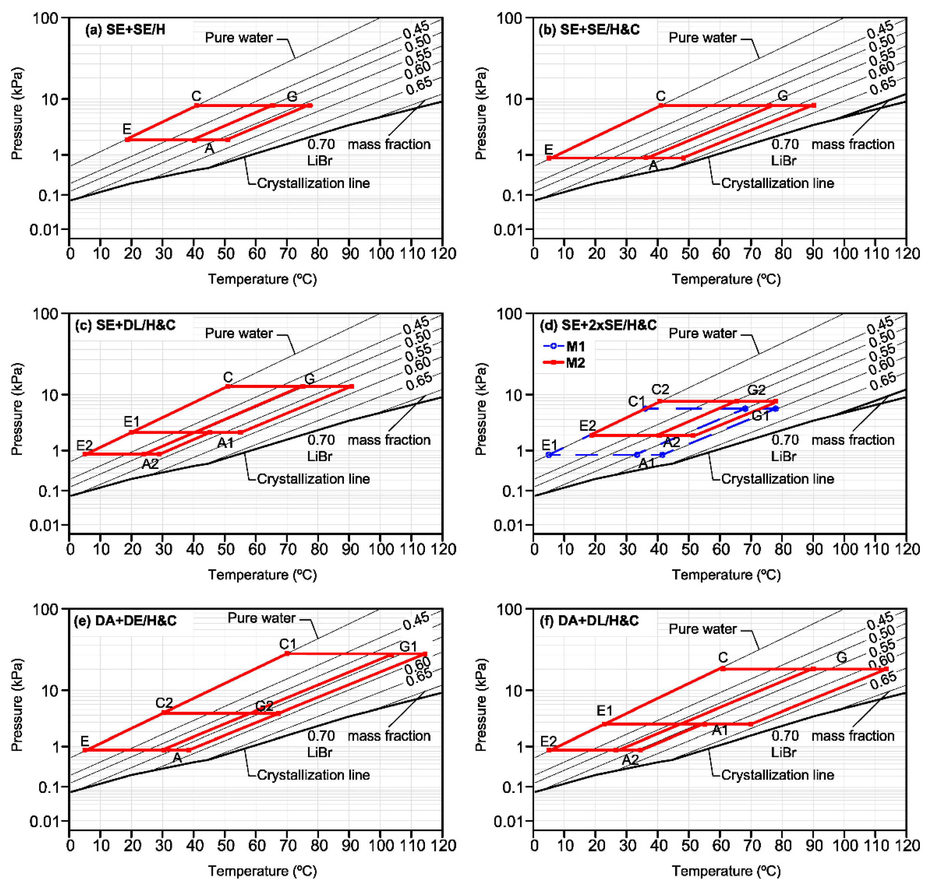
In order to check the feasibility of absorption systems to provide heating and cooling simultaneously at the required conditions, Figure 6 shows the PTX diagram for the step-down thermal substation (SDS) in each system configuration. For the case of the SE + 2xSE/H&C configuration, the two SDS cycles are represented in the same diagram. These diagrams show the performance operation conditions of each configuration. Double-lift AHPs achieve higher heating temperatures than single-effect heat pumps, with the possibility of producing hot and chilled water simultaneously in a single unit and for the same driving temperature. According to Figure 6, it is concluded that all the absorption systems of the SDS operate in a feasible field of temperatures, pressures, and concentrations.
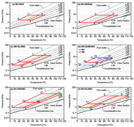
Figure 6.
Dühring plot for the step-down thermal substation (SDS) in each system configuration.
4.2. Overall Results
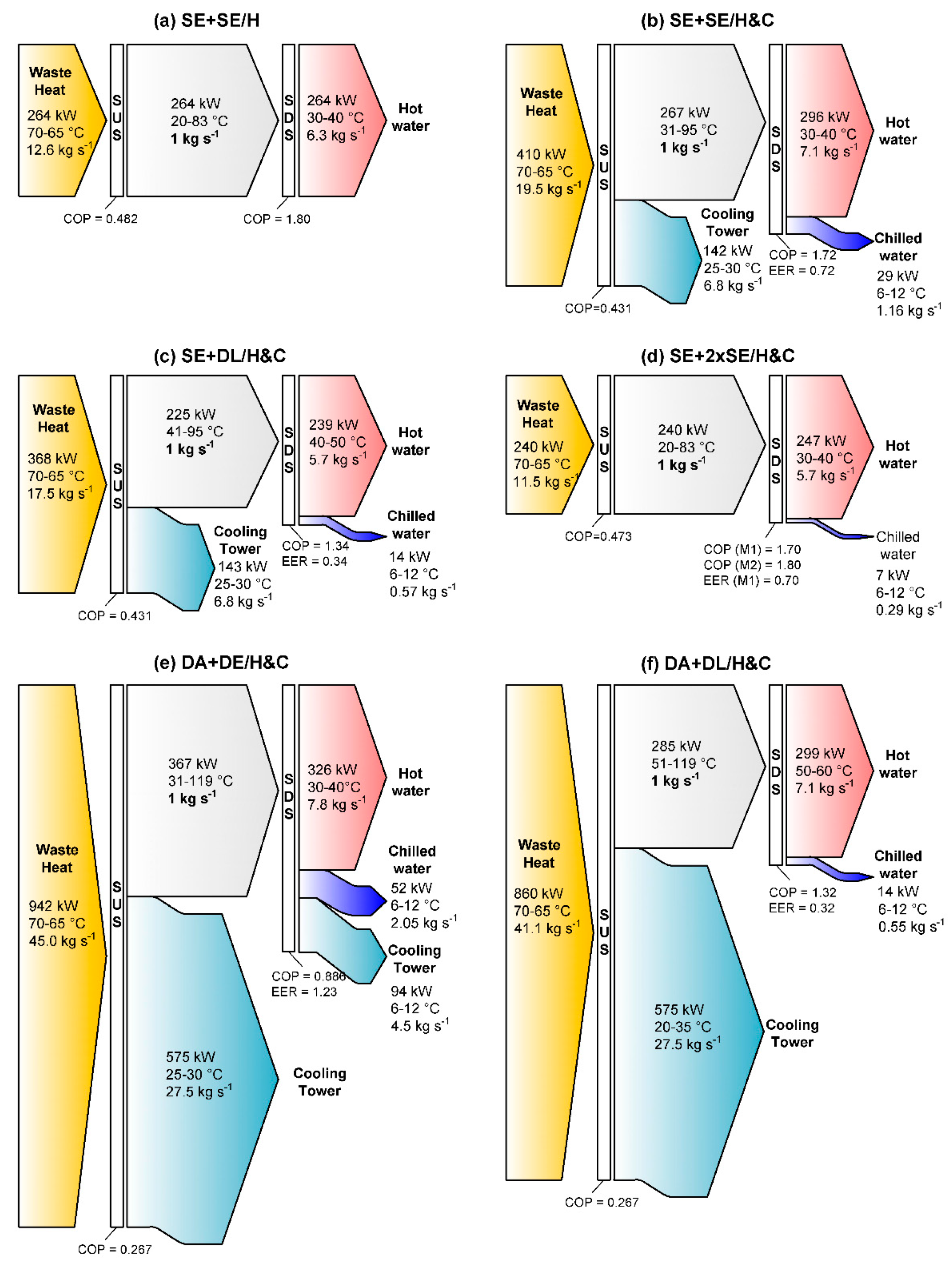
Table 5 summarizes the energy performance of the whole system, including the SUS and SDS, and Figure 7 shows the overall energy flow diagrams for each configuration. The following conclusions can be drawn:
Table 5.
Overall performance results for each system configuration.
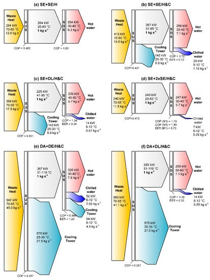
Figure 7.
Energy flows for each system configuration.
- (a)
- In all the studied configurations, the heating provided by the heat pump (QAHP) is always lower than that of the heat exchanger (QHE). In the case of the double effect chiller, it is only possible to provide heat with the external heat exchanger. The best efficiency for heating (COPH,tot) is given by configurations (a) and (d) using single effect absorption units.
- (b)
- The production of cooling is relatively small in all the cases, with the most efficient production of cooling being that of configuration (b).
- (c)
- The system configuration DA + SE/H&C has the highest heating capacity (QH,TOT) but at the expense of a much higher waste heat demand. Thus, the heating efficiency is the lowest for the case configurations (e) and (f) using double absorption systems in the SUS.
- (d)
- Using a double absorption heat transformer in the SUS and double lift absorption units in the SDS in configuration (f) DA + DL/H&C ensures the highest hot water supply temperature (60 °C), but the heating (COPtot) and cooling (EERtot) efficiencies are among the lowest.
- (e)
- Configuration (d) produces cooling with quite similar performance indicators (EqES, exergetic efficiency, etc.) with respect to configuration (a) that only produces heating. However, two absorption units are required. Therefore, the cost could be a serious problem even in the case that a cooling tower is not required neither in the SUS nor in the SDS.
- (f)
- The optimal configuration should be one that does not require the rejection of heat to the ambient atmosphere as is the case of configuration (a) for the production of only heating. The best performance in terms of the avoided consumption of electricity, emissions, and exergetic efficiency is given by the configuration that provides only heating. In the case that cooling is also required, if configuration (d) is considered too costly, then the rejection to the ambient atmosphere cannot be avoided. In that case, it is advisable to choose a configuration where the cooling tower is only needed on the SUS that is reasonable, knowing that it would likely be a centralized unit of high capacity in comparison with an SDS characterized by its location close to each user or group of final users. Thus, configurations (b) or (c) could be selected as the most suitable. Configuration (c) using a double lift offers slightly better performance parameters and heat at a higher temperature but its cooling production is much lower. The final specific application characteristics would be necessary to make a final decision between these two configurations.
Figure 7 illustrates the use of the energy input in each system configuration using the data provided in Table 5. The proposed system using absorption units for the transport of heat and the final distribution of it would be very useful for applications that require heating at low temperatures and relatively low amounts of cooling.
5. Conclusions
The transport of heat using absorption systems is worthy of study for future district heating and cooling networks serving smart communities, where the heating and cooling will be provided by efficient and centralized combined power, heating, and cooling plants using renewables or industrial waste heat. So, the use of gas networks inside cities and large centralized power plants that mainly use fossil fuels could be avoided. This paper explored, analyzed, and compared different configurations to transport heat using absorption systems from waste heat sources to final district heating and cooling networks using step-up (SUS) and step-down (SDS) units in a similar way as that used for electricity transport. It is possible that the upgrade of low temperature waste heat in an absorption heat transformer can be used later in another absorption unit (SDS) to produce heating and cooling for a distribution district network. The production of cooling is quite low, but it could be enough for certain types of users, such as some commercial buildings that need mainly heating but also cooling for certain applications.
The best configuration is the one that does not require the rejection of heat to the ambient atmosphere, as is the case of configuration (a) for the production of heating only. In the case that cooling is also required, if configuration SE + 2xSE/H&C (d) is considered too costly, then the rejection to the ambient atmosphere cannot be avoided. In that case, it is advisable to choose a configuration where the cooling tower is only needed on the SUS, which can reasonably be a centralized unit of higher capacity in comparison with an SDS characterized by its location close to each user or group of final users. Thus, configurations (b) or (c) could be selected as the most suitable. Configuration (c) using a double lift offers better performance parameters but its cooling production is much lower. The final specific application case would be necessary to make the final decision.
Author Contributions
Literature review and paper writing: A.A.-M. and J.C.B., Modelling and simulation: A.A.-M., Conceptualization of configurations and analysis of results J.C.B., Supervision: J.C.B. and A.C. All authors have read and agreed to the published version of the manuscript.
Funding
This research work was financially supported by the Spanish Ministry of Economy and Competitiveness (DPI2015-71306-R).
Acknowledgments
Antonio Atienza-Márquez acknowledges the Spanish Ministry of Education for the financial support of the pre-doctoral contract FPU15/04514.
Conflicts of Interest
The authors declare no conflicts of interest.
Nomenclature
| Abbreviations | |
| A | Absorber |
| AHE | Absorption heat exchanger |
| AHT | Absorption heat transformer |
| AHP | Absorption heat pump |
| C | Condenser |
| COP | Coefficient of Performance (Heating) |
| CT | Cooling tower |
| DA | Double absorption |
| DC | District Cooling |
| DE | Double effect |
| DH | District Heating |
| DL | Double lift |
| E | Evaporator |
| EER | Energy Efficiency Ratio (Cooling) |
| EqES | Equivalent Electricity Saving |
| HE | Heat exchanger |
| G | Generator/desorber |
| SDS | Step-Down Substation |
| SE | Single effect |
| SHE | Solution heat exchanger |
| SUS | Step-Up Substation |
| Variables | |
| COP | Coefficient of Performance (heating) |
| Cp | Heat Capacity, kJ/kgK |
| EER | Energy Efficiency Ratio (cooling) |
| h | Enthalpy, kJ/kg |
| m | Mass flow rate, kg/s |
| P | Pressure, kPa |
| PC | Primary circuit |
| PER | Primary energy rate |
| Q | Heat (kW) |
| T | Temperature, K |
| x | Mass fraction of lithium bromide in solution, % |
| W | Power, kW |
| Greek letters | |
| Delta | Difference |
| epsilon | Effectiveness |
| eta | Efficiency |
| Subscripts | |
| A | Absorber |
| C | Condenser or cooling |
| CT | Cooling tower |
| E | Evaporator |
| G | Generator |
| h | High |
| H | Heating |
| l | Low |
| R | Return |
| ref | Reference value |
| S | Supply |
| tot | Total |
| WH | Waste heat |
References
- Brückner, S.; Liu, S.; Miró, L.; Radspieler, M.; Cabeza, L.F.; Lävemann, E. Industrial waste heat recovery technologies: An economic analysis of heat transformation technologies. Appl. Energy. 2015, 151, 157–167. [Google Scholar] [CrossRef]
- Papapetrou, M.; Kosmadakis, G.; Cipollina, A.; La Commare, U.; Micale, G. Industrial waste heat: Estimation of the technically available resource in the EU per industrial sector, temperature level and country. Appl. Therm. Eng. 2018, 138, 207–216. [Google Scholar] [CrossRef]
- Herold, K.E.; Radermacher, R.; Klein, S.A. Absorption Chillers and Heat Pumps, 2nd ed.; CRC Press: Boca Raton, FL, USA, 2016; ISBN 9781498714341. [Google Scholar]
- Li, Y.; Fu, L.; Zhang, S.; Jiang, Y.; Xiling, Z. A new type of district heating method with co-generation based on absorption heat exchange (co-ah cycle). Energy Convers. Manag. 2011, 52, 1200–1207. [Google Scholar] [CrossRef]
- Sun, F.; Fu, L.; Zhang, S.; Sun, J. New waste heat district heating system with combined heat and power based on absorption heat exchange cycle in China. Appl. Therm. Eng 2012, 37, 136–144. [Google Scholar] [CrossRef]
- Xie, X.; Jiang, Y. Absorption heat exchangers for long-distance heat transportation. Energy 2017, 141, 2242–2250. [Google Scholar] [CrossRef]
- Jiang, Y.; Xie, X. Absorption heat exchangers for long distance heat transportation. In Proceedings of the International Congress Refrigeration 2015, Yokohama, Japan, 16–22 August 2015; p. 13. [Google Scholar] [CrossRef]
- Xie, X.; Jiang, Y. Temperature Efficiency Analysis of Absorption Heat Exchangers. In Proceedings of the International Congress Refrigeration 2015, Yokohama, Japan, 16–22 August 2015; p. 8. [Google Scholar] [CrossRef]
- Zhu, C.; Xie, X.; Jiang, Y. A multi-section vertical absorption heat exchanger for district heating systems. Int. J. Refrig. 2016, 71, 69–84. [Google Scholar] [CrossRef]
- Sun, J.; Fu, L.; Zhang, S. Experimental study of heat exchanger basing on absorption cycle for CHP system. Appl. Therm. Eng. 2016, 102, 1280–1286. [Google Scholar] [CrossRef]
- Sun, F.; Cheng, L.; Fu, L.; Gao, J. New low temperature industrial waste heat district heating system based on natural gas fired boilers with absorption heat exchangers. Appl. Therm. Eng. 2017, 125, 1437–1445. [Google Scholar] [CrossRef]
- Sun, F.; Zhao, J.; Fu, L.; Sun, J.; Zhang, S. New district heating system based on natural gas-fired boilers with absorption heat exchangers. Energy 2017, 138, 405–418. [Google Scholar] [CrossRef]
- Yang, B.; Jiang, Y.; Fu, L.; Zhang, S. Modular simulation of cogeneration system based on absorption heat exchange (Co-ah). Energy 2018, 153, 369–386. [Google Scholar] [CrossRef]
- Sun, J.; Ge, Z.; Fu, L. Investigation on operation strategy of absorption heat exchanger for district heating system. Energy Build. 2017, 156, 51–57. [Google Scholar] [CrossRef]
- Wang, X.; Zhao, X.; Fu, L. Entransy analysis of secondary network flow distribution in absorption heat exchanger. Energy 2018, 147, 428–439. [Google Scholar] [CrossRef]
- Lund, H.; Ostergaard, P.A.; Chang, M.; Wemer, S.; Svendsen, S.; Sorknaes, P.; Thorsen, J.E.; Hvelplund, F.; Mortensen, B.O.G.; Mathiesen, B.V.; et al. The status of 4th generation district heating: Research and results. Energy 2018, 164, 147–159. [Google Scholar] [CrossRef]
- Werner, S. International review of district heating and cooling. Energy 2017, 137, 617–631. [Google Scholar] [CrossRef]
- Buffa, S.; Cozzini, M.; D’Antoni, M.; Baratieri, M.; Fedrizzi, R. 5th generation district heating and cooling systems: A review of existing cases in Europe. Renew. Sustain. Energy Rev. 2019, 104, 504–522. [Google Scholar] [CrossRef]
- Güido, W.H.; Lanser, W.; Petersen, S.; Ziegler, F. Performance of absorption chillers in field tests. Appl. Therm. Eng. 2018, 138, 353–359. [Google Scholar] [CrossRef]
- F-Chart Software, Engineering Equation Solver (EES). 2016. Available online: http://www.fchart.com/ees/ (accessed on 1 March 2019).
- Rivera, W.; Best, R.; Cardoso, M.J.; Romero, R.J. A review of absorption heat transformers. Appl. Therm. Eng. 2015, 91, 654–670. [Google Scholar] [CrossRef]
- Parham, K.; Khamooshi, M.; Tematio, D.B.K.; Yari, M.; Atikol, U. Absorption heat transformers—A comprehensive review. Renew. Sustain. Energy Rev. 2014, 34, 430–452. [Google Scholar] [CrossRef]
- Honga, S.J.; Lee, C.H.; Kim, S.M.; Kim, I.G.; Kwon, O.K.; Park, C.W. Analysis of single stage steam generating absorption heat transformer. Appl. Therm. Eng. 2018, 144, 1109–1116. [Google Scholar] [CrossRef]
- Wang, D.; Li, S.; Liu, F.; Gao, L.; Sui, J. Post combustion CO2 capture in power plant using low temperature steam upgraded by double absorption heat transformer. Appl. Energy 2018, 227, 603–612. [Google Scholar] [CrossRef]
- Mahmoudi, S.M.S.; Salehi, S.; Yari, M. Three-objective optimization of a novel triple-effect absorption heat transformer combined with a water desalination system. Energy Convers. Manag. 2017, 138, 131–147. [Google Scholar] [CrossRef]
- Ayou, D.S.; Currás, M.R.; Salavera, D.; García, J.; Bruno, J.C.; Coronas, A. Performance analysis of absorption heat transformer cycles using ionic liquids based on imidazolium cation as absorbents with 2,2,2-trifluoroethanol as refrigerant. Energy Convers. Manag. 2014, 84, 512–523. [Google Scholar] [CrossRef]
- Saito, K.; Inoue, N.; Nakagawa, Y.; Fukusumi, Y.; Yamada, H.; Irie, T. Experimental and numerical performance evaluation of double-lift absorption heat transformer. Sci. Technol. Built Environ. 2015, 21, 312–322. [Google Scholar] [CrossRef]
- Martínez, H.; Rivera, W. Energy and exergy analysis of a double absorption heat transformer operating with water/lithium bromide. Int. J. Energy Res. 2009, 33, 662–674. [Google Scholar] [CrossRef]
- Zhao, Z.; Ma, Y.; Chen, J. Thermodynamic performance of a new type of double absorption heat transformer. Appl. Therm. Eng. 2003, 23, 2407–2414. [Google Scholar] [CrossRef]
- Mostofizadeh, C.; Kulick, C. Use of a new type of heat transformer in process industry. Appl. Therm. Eng. 1998, 18, 857–874. [Google Scholar] [CrossRef]
- Ma, Z.; Bao, H.; Roskilly, A.P. Performance analysis of ultralow grade waste heat upgrade using absorption heat transformer. Appl. Therm. Eng. 2016, 101, 350–361. [Google Scholar] [CrossRef]
- Medrano, M.; Bourouis, M.; Coronas, A. Double-lift absorption refrigeration cycles driven by low–temperature heat sources using organic fluid mixtures as working pairs. Appl. Energy 2001, 68, 173–185. [Google Scholar] [CrossRef]
- Kim, D.S.; Infante Ferreira, C.A. Air-cooled LiBr–water absorption chillers for solar air conditioning in extremely hot weathers. Energy Convers. Manag. 2009, 50, 1018–1025. [Google Scholar] [CrossRef]
- Xu, Z.Y.; Wang, R.Z. Absorption refrigeration cycles: Categorized based on the cycle construction. Int. J. Refrig. 2016, 62, 114–136. [Google Scholar] [CrossRef]
- Atienza-Márquez, A.; Cejudo, J.M.; Fernández, F.; Domínguez, F.; Carrillo, A. A comparison of heating terminal units: Fan-coil versus radiant floor, and the combination of both. Energy Build. 2017, 138, 621–629. [Google Scholar] [CrossRef]
- Kärkkäinen, S. Heat Pumps for Cooling and Heating; International Energy Agency Demand-Side Management Programme: Espoo, Finland, 2008. [Google Scholar]
- ASHRAE. ASHRAE Handbook-Refrigeration, SI ed.; American Society of Heating, Refrigerating and Air-Conditioning Engineers, Inc.: Atlanta, GA, USA, 2014. [Google Scholar]

© 2019 by the authors. Licensee MDPI, Basel, Switzerland. This article is an open access article distributed under the terms and conditions of the Creative Commons Attribution (CC BY) license (http://creativecommons.org/licenses/by/4.0/).