Article

Wire Electrochemical Machining with Pulsating Radial Electrolyte Supply and Preparation of Its Tube Electrode with Micro-Holes

National Key Laboratory of Science and Technology on Helicopter Transmission, Nanjing University of Aeronautics and Astronautics, Nanjing 210016, China
*
Author to whom correspondence should be addressed.
Appl. Sci. 2020, 10(1), 331; https://doi.org/10.3390/app10010331
Submission received: 6 December 2019 / Revised: 21 December 2019 / Accepted: 22 December 2019 / Published: 2 January 2020
(This article belongs to the Section Mechanical Engineering)

Abstract

:

Featured Application

Low-cost manufacture of turbine slots with well surface integrity.

Abstract

Wire electrochemical machining (WECM) has great advantages and potential for fabricating parts with ruled surfaces made of difficult-to-machine materials. Characterized by a relatively short flow path, a pulsating radial electrolyte supply in WECM is proposed to improve the machining capability for thick workpieces. The tool is a tube electrode with a line of micro-holes on cylindrical surface. This paper introduces research into the processing of micro-holes in the tube electrode using a rotating helical electrode. The quantitative relationship among the feed rate, the applied voltage, and the diameter of the outlet holes was determined experimentally. A tube electrode with holes of varying diameters was fabricated by adjusting the applied voltage. Using it as a tool electrode, kerfs with a length of 10 mm and an averaged width of 0.903 mm were machined at a feed rate of 6 μm/s in a 30 mm-thick block, and there was no short circuit during processing. It was shown experimentally that using a tube electrode with holes of varying diameters as a tool electrode provides better process capacity for pulsating radial electrolyte supply in WECM.

1. Introduction

Low-cost precision machining presents a bottleneck when fabricating parts with ruled surfaces like the fir-tree slots in a turbine disc [1]. They are commonly made of difficult-to-cut materials such as nickel-based alloys and titanium alloys, and require strict surface integrity, allowing no recast layers nor microcracks. Wire electrochemical machining (WECM) uses a metal wire as the tool cathode and removes material by anodic electrochemical dissolution, and the part is formed with the relative motion between the wire electrode and the workpiece. WECM has great advantages and well surface integrity such as no dependence on mechanical properties of the material being machined, no tool wear, no residual stress, no recast layers, or heat-affected zones. Hence, it is a potential method for processing parts with ruled surfaces made of difficult-to-cut materials [2,3].
In WECM, the machining gap is usually tens of microns down to only a few microns, making it very difficult to rapid remove electrolytic products entirely from such a small gap. To expedite the elimination of electrolytic products, Zhu et al. [4] utilized a tungsten wire with vibration and fabricated a micro-blade structure on a 100 μm-thick nickel plate. Shin et al. [5] applied ultrashort voltage pulses to machine micro grooves and gears on 100-μm-thick stainless steel plates. However, when the workpiece thickness reaches millimeter level, the amount of electrolytic products in WECM increases sharply. They will accumulate continuously in the gap, thereby leading to an uneven distribution of electrolyte conductivity, inhomogeneous material dissolution, as well as deteriorated machining accuracy. In severe cases, the material can no longer dissolve, whereupon the continuous feeding of the wire electrode results in short circuits and processing failure. The aforementioned micro-amplitude vibration has little effect on machining macro structures.
Much research has been conducted to improve the outcome of WECM on thick workpieces, and they can be divided into two categories according to the electrolyte flow status. In the first category, the workpiece is immersed in electrolyte, and the electrolyte in machining gap flows following the electrode movement. Kalaimathi et al. [6] used the oscillating-wire method to machine 20-mm-thick Monel 400 alloys. Fang et al. [7] carried out research on WECM, adopting a ribbed wire electrode with large-amplitude vibration, and Zou et al. [8] used an edge-cutting electrode; they were able to manufacture a 5-mm-thick fir-tree slit. Fang et al. [9] and Volgin et al. [10] proposed the methods of using a rotating helical electrode and electrodes with non-circular cross sections, respectively, to enhance the electrolyte refreshment. The second category is axial electrolyte flushing. The electrolyte with a certain pressure is ejected from the nozzle, and flows into the machining gap along the electrode, which brings the electrolyte products out of the machining gap from top to bottom. High-speed flushing is the most commonly used method to promote electrolyte renewal and replenishment. Maeda et al. [11] studied the influence of wire and voltage parameters, nozzle diameter, and velocity of the electrolyte flow on the feed rate in WECM with axial electrolyte flushing. Qu et al. [12] machined 1.8 mm thick titanium alloy with wire electrode of 0.1 mm diameter, and the feed rate could achieve 1.8 mm/min. He et al. [13] performed experiments on TiAl alloy of thickness 10 mm, and the feed rate was 0.18 mm/min. Béjar et al. [14] machined 6-mm-thick mild steel using axial electrolyte flushing, and the maximum feed rate was 2.5 mm/min. Klocke et al. [15] combined axial electrolyte flushing with rotating two twisted wires to optimize the electrolyte flushing, and machined Inconel 718 of thickness 40 mm with the cutting rate up to 20 mm2/min. However, the maximum feed rates decrease significantly with the increase of workpiece thickness.
Although the above methods do accelerate the electrolyte renewal and the products removal, they still suffer the disadvantage of a long flow path, meaning that fresh electrolyte has relatively far to travel to reach the reaction area. Herein, we propose a novel pulsating radial electrolyte supply for WECM, which utilized a tube electrode with a line of micro-holes on surface. The electrolyte is pumped into the tube electrode from two ends and is ejected into the machining gap from the radial micro-holes of the tube. In this way, the electrolyte refreshment has a relatively short path, being independent of the workpiece thickness. The micro-hole size as well as its distribution will indeed have an important effect on the radial flow field uniform and the process stability. As a common micro-structure, micro-holes have been used widely in various parts, but their fabrication has invariably been a difficult problem in drilling thin-walled parts. Mechanical drilling has the disadvantages of severe tool wear and deformation, and defects such as thermal deformation, heat-affected layers and recast layers arise at the edges of the holes processed by electrical discharge machining and laser micromachining [16,17]. By contrast, electrochemical micro-drilling (ECMD) is more suitable for fabricating micro-holes because of its good surface quality and absence of stress. Tsui et al. [18] found using a micro helical tool could improve the accuracy of micro-holes significantly. Liu et al. [19] machined taper free micro-holes with a diameter of 186 µm on the GH4169 plate of 500 µm thickness using a rotating helical electrode and ultra-short voltage pulse.
However, there is a lack of research on drilling micro-holes on cylindrical surface. Herein, we present research into the processing of micro-holes on cylindrical surface fabricated by a rotating helical electrode. After determining the quantitative relationship among the feed rate, the applied voltage, and the hole diameter, a tube with holes of varying diameters is machined by regulating the applied voltage on-line. Then, experiments are carried out to verify whether a tube electrode with varying micro-holes offers a better processing capacity for supplying pulsating radial electrolyte in WECM of a 30 mm-thick workpiece.

2. Methods

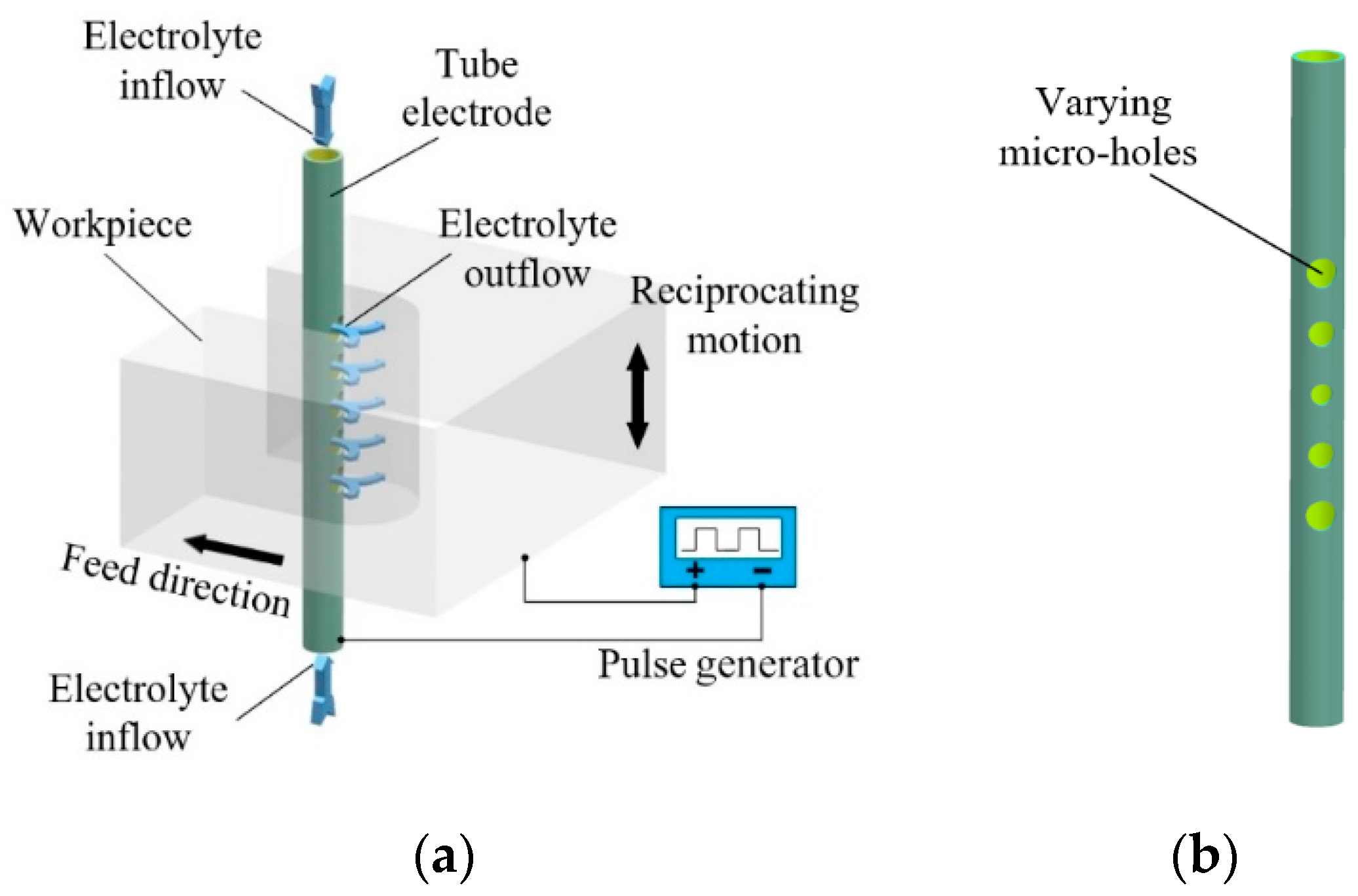
2.1. Principle of WECM with Pulsating Radial Electrolyte Supply

Figure 1a shows the principle of WECM with pulsating radial electrolyte supply. Fresh electrolyte flows into the two ends of the tube electrode, flows out from the holes on surface, then through the machining gap, and finally out from behind the tube electrode. During processing, the holes on the tube electrode are always facing the machining area along with the axial vibration of electrode or workpiece. Thus, fresh electrolyte directly enters the machining area after being ejected from the holes. The proposed method shortens the flow path greatly, decreases the flow resistance of electrolyte, and strengthens its flushing ability. For every point in the machining gap, the electrolyte pressure and flow rate fluctuate periodically, keeping a dynamic uniform distribution. By means of separating micro-holes on the tube electrode, the workpiece is separated into several regions in its thickness direction. Fresh electrolyte can directly reach the electrode surface in the whole thickness range of the workpiece at the same time, and quickly participate in electrochemical reaction, which improves the ability of cutting thick workpiece. Therefore, pulsating radial supply of electrolyte in WECM could enhance the mass transfer, thereby greatly ameliorating the situation in which transmission of electrolyte is limited in the narrow machining gap for thick workpieces. However, since the electrolyte enters from both ends of the tube electrode, it is squeezed at the intermediate position, causing the electrolyte pressure in the intermediate portion to be higher than both sides. If the diameters of the holes are uniform, there will be a difference in flow rate of each hole. The electrolyte supply on both sides is likely to be insufficient, which may affect the process stability. Increasing the flow rate of the holes on both sides by increasing the diameter should be an effective method to reduce the difference in flow rates of holes at different locations. Thus, a tube electrode with varying micro-holes shown in Figure 1b is in need. In this paper, the tube electrode has a wall thickness of 0.1 mm and an outer diameter of 0.7 mm.

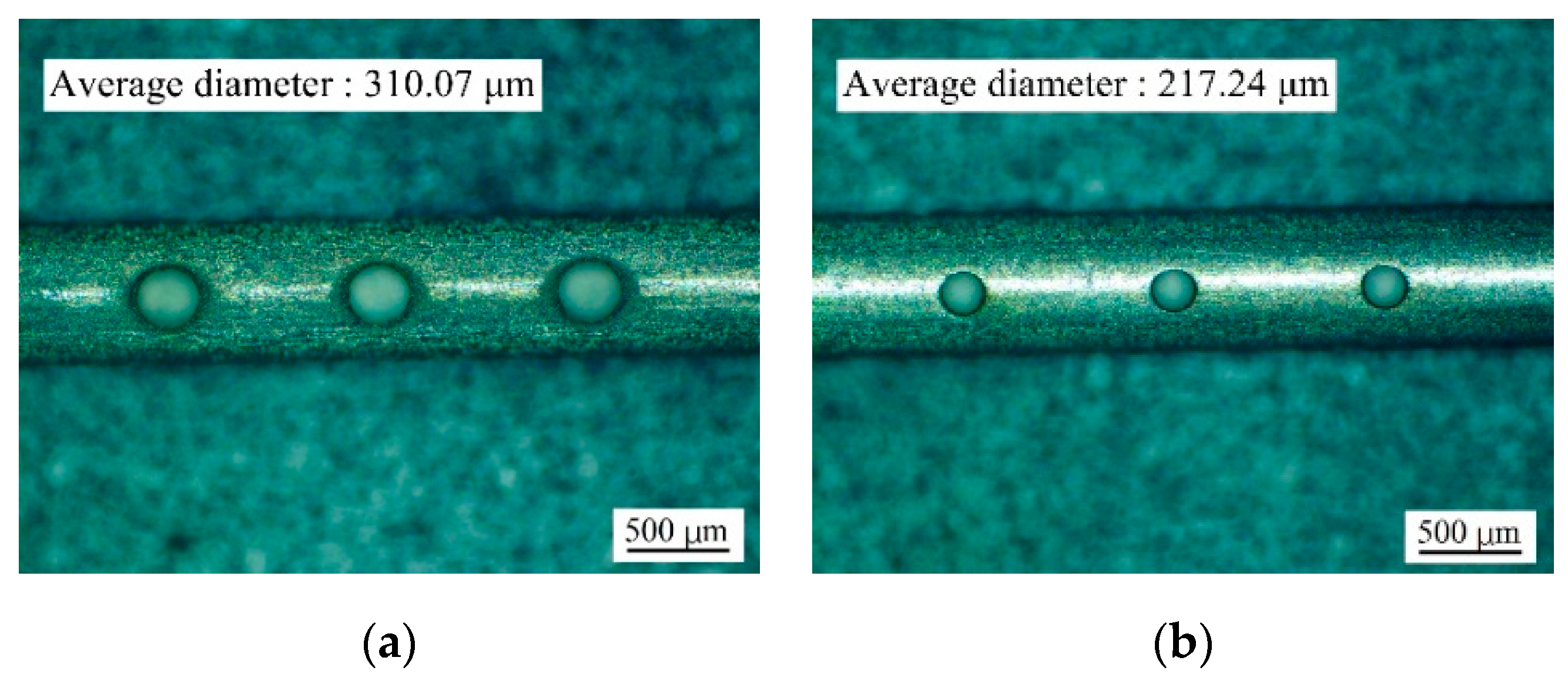
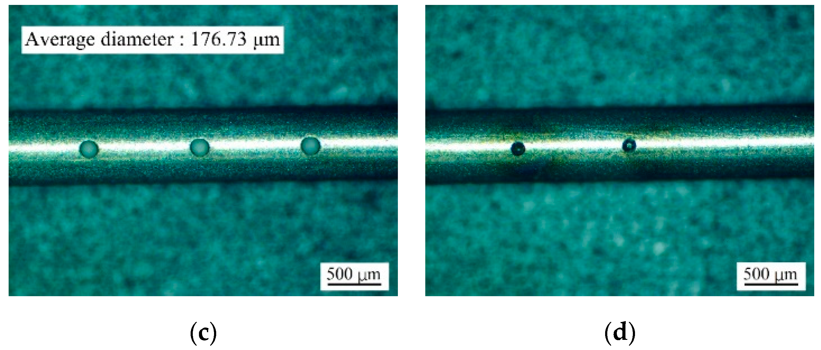
2.2. Drilling Varying Micro-Holes with ECMD on a Tube Electrode

As illustrated in Figure 2, a rotating helical drill serves as the tool electrode and is connected to a spindle rotating at fast rotation rate. A micro-hole gradually generates when the tool electrode is fed downward. The electrolyte in the machining gap is driven to stream upward from the bottom because of the rotation of the helical electrode. Consequently, electrolysis products are taken out of the processing gap while forcing new electrolyte to take its place. The rotating helical electrode promotes renewal of the electrolyte, hence the stability of processing is enhanced. For the present investigation, a micro-drill with a diameter of 100 μm was used, and a tube electrode made of stainless steel was submerged in electrolyte.
Figure 3 illustrates the experimental setup for ECMD comprising X–Y motion modules, a Z motion module, an oscilloscope, a pulse generator, and a spindle. The motion modules adopt the structure of linear motor and air floating guide rail, and the grating ruler is used as the feedback element, with the resolution of 20 nm and the accuracy of ±1 μm. The pulse generator supply can provide a voltage of 0–40 v. The maximum output power is 1200 W, and maximum output current is 30 A. Maximum frequency provided by the generator is up to 100 kHz. Pulse duty cycle can be adjusted from 0 to 100%. The spindle rotates at 5000 rpm, and the electrolyte is a 50 g/L sodium nitrate solution. The tube electrode is cleaned ultrasonically prior to the experiment. The diameter of fabricated micro-holes is measured using a microscope (STM7; Olympus, Tokyo, Japan), and the hole shape is photographed.

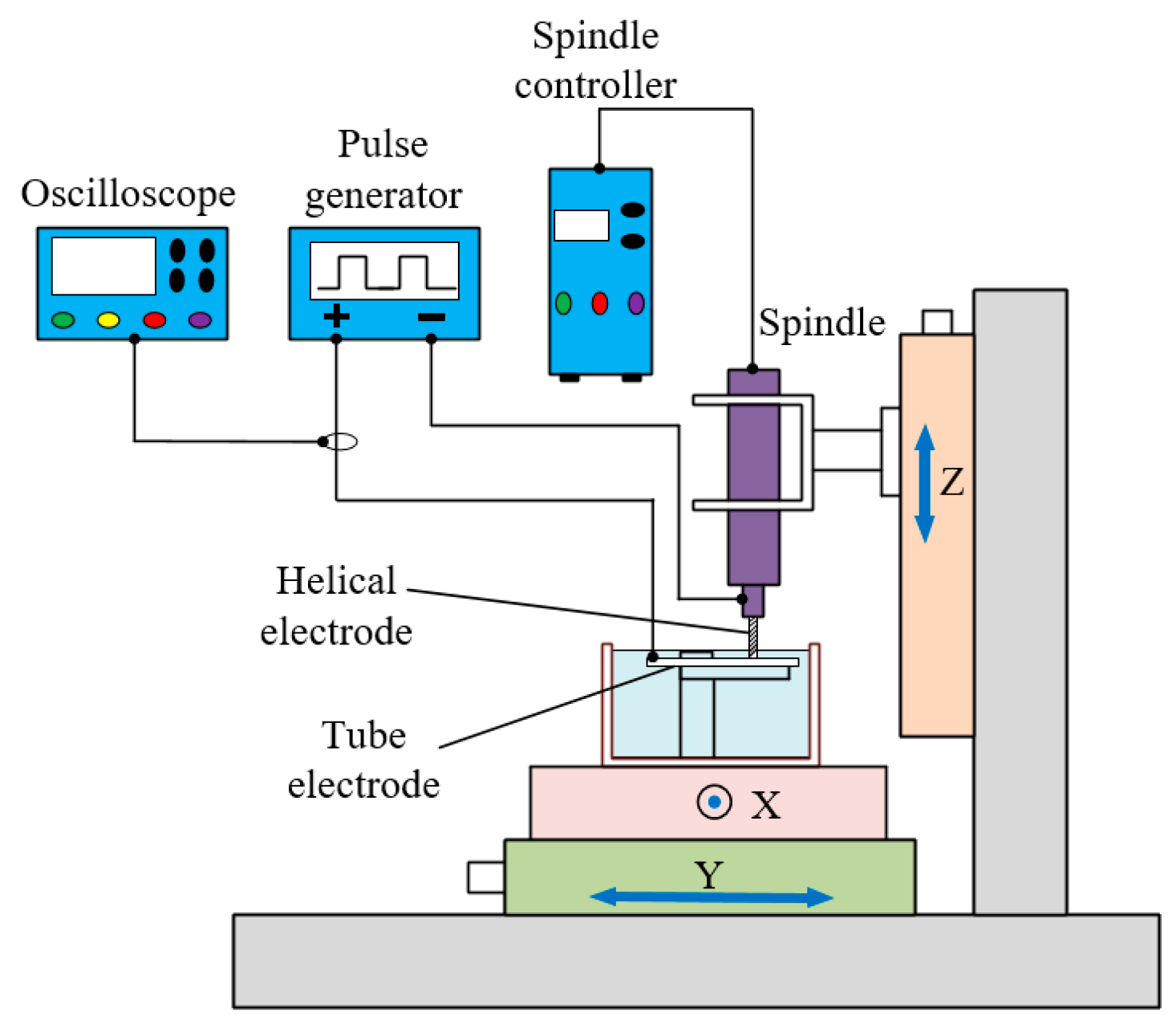
2.3. Experimental Procedures

According to the parameters listed in Table 1 and Table 2, micro-holes were machined on tube electrodes to investigate the influence of pulse duty cycle and frequency on the diameter and shape of holes. The average diameter of micro-holes is the average value of the diameter of three consecutive micro-holes. The optimum pulse duty cycle and frequency based on surface quality and processing accuracy are determined experimentally.
Using the optimum pulse duty cycle, frequency, and parameters listed in Table 3, experiments were performed three times to find the relationship among the feed rate, the applied voltage, and the diameter of the outlet holes. A feed rate of 2 μm/s is used to produce holes of different diameter, and the required voltage is calculated using the quantitative relationship.
Cutting experiments were performed using tube electrodes with a line of micro-holes on cylindrical surface. The processing parameters are an applied pulse voltage amplitude of 20 V, a duty cycle of 40%, a frequency of 50 kHz, a workpiece vibration frequency of 1.5 Hz, a vibration amplitude of 1 mm, a feed rate of 6 μm/s, an electrolyte pressure of 1 MPa, and sodium nitrate solution at a concentration of 200 g/L as the electrolyte. The workpiece made of stainless steel with a thickness of 30 mm was polished and ultrasonically cleaned before the experiment.

3. Results and Discussion

3.1. Influence of Pulse Duty Cycle

Figure 4 shows the photographs of holes machined with different values of the duty cycle. With the increase of the duty cycle, stray corrosion is clearly more severe. The hole diameter decreases gradually when the duty cycle is reduced from 50% to 20%. However, when the duty cycle is reduced to 10%, short circuits occur during processing and the hole fabrication fails. Too small duty cycle results in less material being removed, which eventually leads to short circuits between the helical electrode and the tube. Zou et al. [20] reported that too small duty cycle will bring about unstable processing. This result is consistent with the report. Therefore, to obtain better processing quality while avoiding a short circuit, we select 20% as the duty cycle.

3.2. Influence of Pulse Frequency

Figure 5 shows the photographs of holes machined with different values of the frequency, and with the increase of the frequency stray corrosion is clearly reduced. Double-layer charging is present in high-frequency pulsed ECM. Because the charging time is constant, the effective machining time decreases as the pulse frequency is increased. This decreases the material removal rate, which explains why the diameter decreases at a higher pulse frequency. The result concurs with the report that the localization of ECM can be improved by using ultrashort pulse [21]. Consequently, to achieve higher machining accuracy and better processing quality, we select 100 kHz as the frequency.

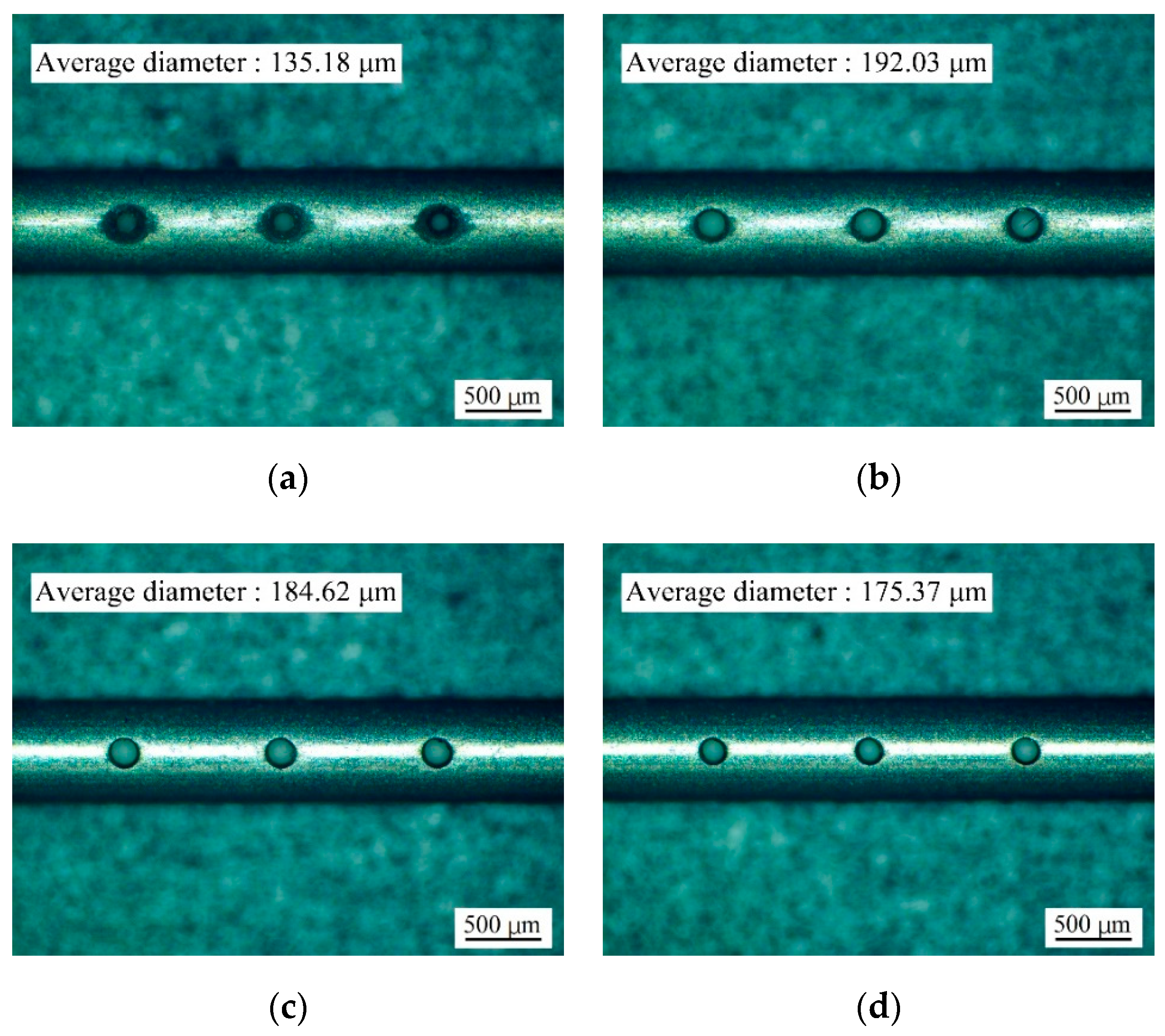
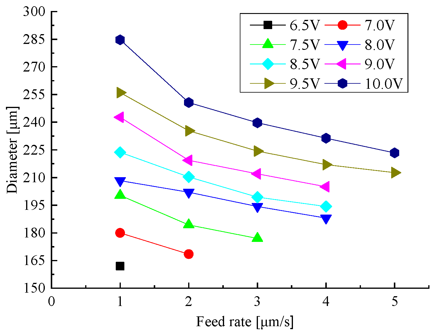
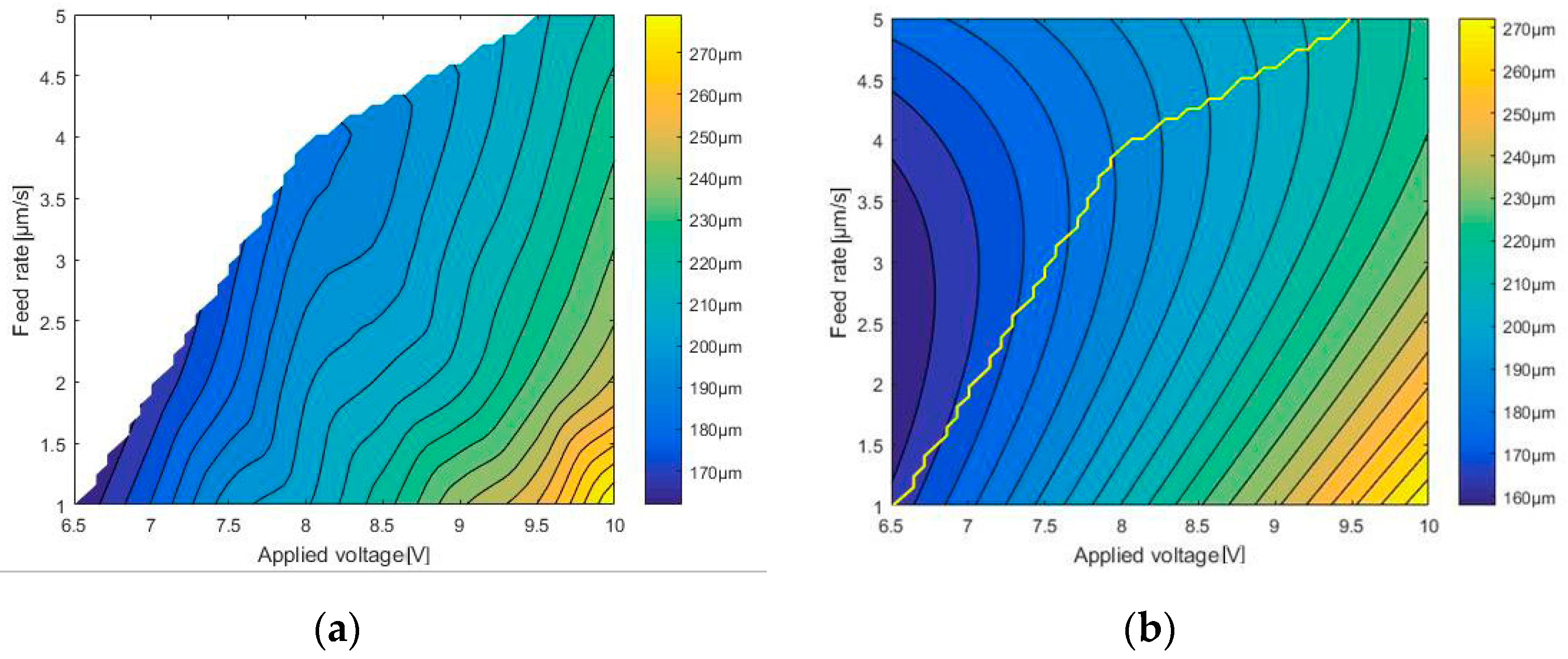
3.3. Influence of Feed Rate and Applied Voltage

We study experimentally how the hole diameter depends on the feed rate and the applied voltage, and conclude from the measurements and the calculated average values that the diameter is between 162.00 μm and 284.67 μm. Figure 6 shows that the diameter increases with decreasing feed rate and increasing applied voltage.
Using multivariate regression analysis, the quantitative relationship among the diameter D, the feed rate V, and the applied voltage U is:
D = 22.13 + 15.57U + 15.17V + 1.3U2 − 4.819UV + 3.208V2
Figure 7a shows a three-dimensional shape achieved by cubic spline interpolation based on experimental results. Figure 8a shows a contour plot of the diameter, showing how the feed rate and the applied voltage influence the diameter. Figure 7b and Figure 8b show the results corresponding to Figure 7a and Figure 8a, but plotted using Equation (1). The left side of the yellow lines in Figure 7b and Figure 8b are generated by equation, which cannot be acquired by experiments. On the contrary, the right side can be actually obtained. The fitting error between the two sets of results is less than ±7 μm, and shown in Figure 7c. Then, we could find a reasonable parameter combine from the equation or the contour plot when drilling a specific diameter micro-hole.

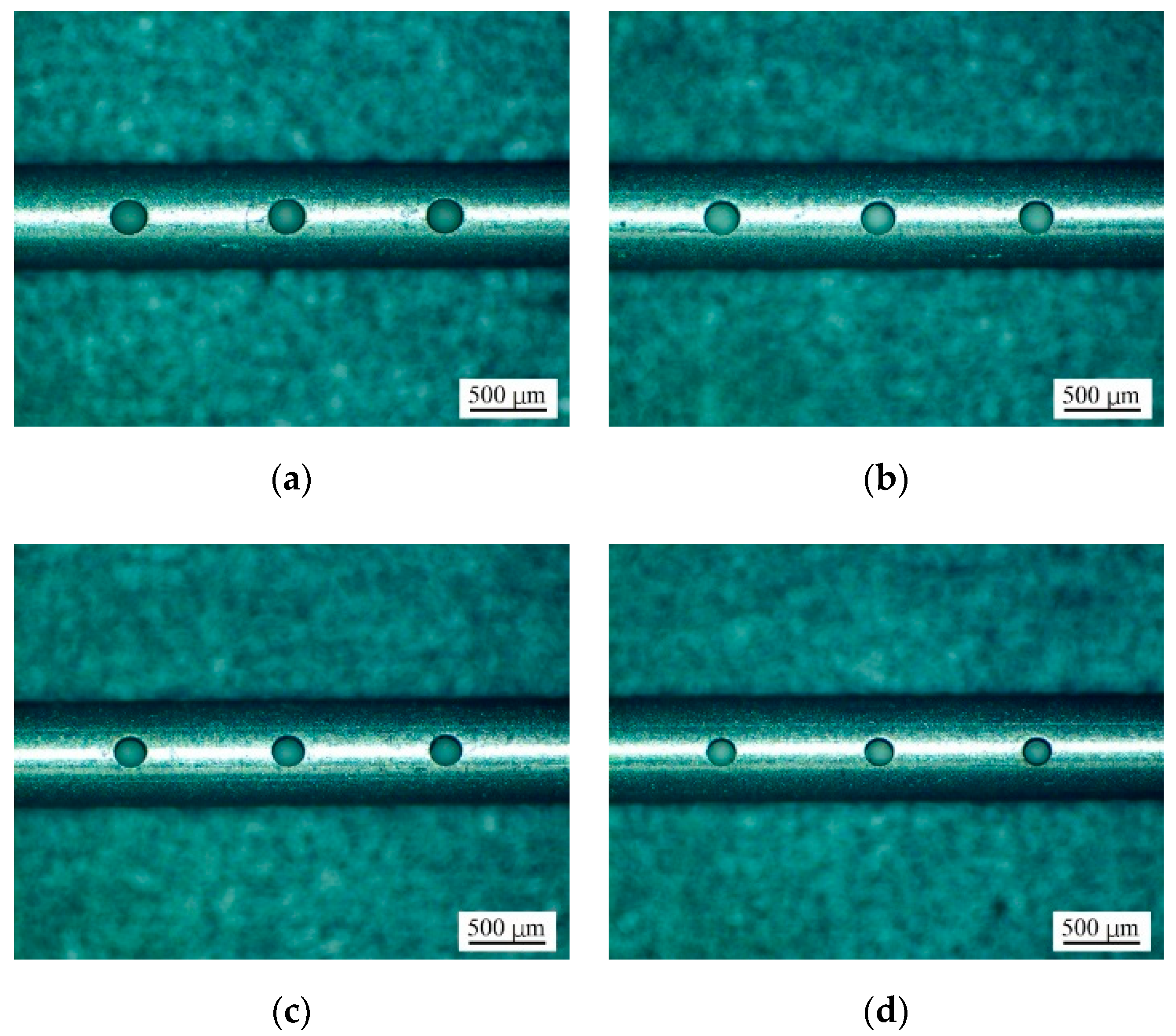
3.4. Drilling Varying Holes with Different Applied Voltages at a Same Feed Rate

Table 4 details results of fabricated holes of different diameters. The applied voltage in the table is calculated by Equation (1) using desired diameters and a feed rate of 2 μm/s. Figure 9 shows the photographs of the holes of different diameter fabricated with the same feed rate. The manufactured tube electrode has a good surface quality and is almost free of stray corrosion, thereby showing the feasibility of fabricating variable-diameter holes by adjusting the applied voltage on-line.

4. WECM with Pulsating Radial Electrolyte Supply

4.1. Preparation of Tube Electrodes

For machining 30 mm-thick workpiece, a tube electrode with 30 holes with spacing of 1 mm and workpiece vibration amplitude of 1 mm are set up, so that the span of the highest and lowest holes can reach 30 mm in WECM with pulsating radial electrolyte supply. First, a tube electrode with uniform-diameter holes of 0.2 mm is machined with a feed rate of 2 μm/s and an applied voltage of 8.15 V, as shown in Figure 10a. However, using it as tool electrode, short circuits occur on the top and bottom surfaces during the cutting process, because the supply of electrolyte is insufficient from holes on both sides. Hence, the distribution of the micro-hole diameter is improved. Figure 11 compares the uniform-diameter and varying-diameter cases. The two electrolyte models with different diameter distribution shown in Figure 10a were applied to flow field simulation. As seen from Figure 11b, the flow rate of holes on both sides can be measurably increased and the consistency of flow rate of outlet holes can be improved by adopting varying-diameter. As shown in Figure 10b, a tube electrode with varying-diameter holes is fabricated by adjusting the applied voltage as listed in Table 5.

4.2. Cutting Kerfs on a 30 mm-Thick Block

The tube electrodes fabricated by ECMD are taken as tool cathodes for WECM with pulsating radial electrolyte supply. Photographs of WECM are shown in Figure 12. The experimental setup mainly includes an oscilloscope, a pulse generator, an electrolyte circulation apparatus, X–Y–Z motion modules and fixtures. The function of pumping the fresh electrolyte as well as filtering out the by-product is realized by the electrolyte circulation apparatus. The position of the cathode is fixed by the cathode fixture, and the anode is fixed on the motion modules.
Figure 13 shows the different current status with different electrodes. Serious sparking and short circuits occur frequently, and the machining cannot be continued. The kerf length is less than 3 mm. It can be seen from Figure 14 that severe burns occurred on the surface of the workpiece. By contrast, three kerfs with a length of 10 mm and an averaged width of 0.903 mm can be machined using the varying-diameter tube electrode as the tool as shown in Figure 15. The current is stable and there is no short circuit during the process. The electrical current density in the machining gap is 0.294 A/mm2. The experiments show that using a tube electrode with variable micro holes offers a better processing capacity for pulsating radial electrolyte supply in WECM.

5. Conclusions

In this paper, we proposed a novel pulsating radial electrolyte supply method for WECM, which is utilized by a tube electrode with a line of micro-holes on surface. And it is proposed to electrochemically drill micro-holes of different diameters on surface of tube electrodes by adjusting the applied voltage online. We draw the following conclusions from the present experiments:
(1)
To obtain higher machining accuracy and better processing quality, a duty cycle of 20% and a pulse frequency of 100 kHz were used.
(2)
Using multivariate regression analysis, the quantitative relationship among the applied voltage, the electrode feed rate, and the diameter of the side holes was determined. The feasibility of fabricating tube electrodes with varying-diameter holes in the side by regulating the applied voltage on-line was shown.
(3)
Using the varying-diameter tube electrode, three kerfs with a length of 10 mm and an averaged width of 0.903 mm can be machined at a feed rate of 6 μm/s in 30-mm-thick block, and there are no short circuits during processing.
(4)
Experiments shown that using a tube electrode with micro-holes of variable diameter provides better processing capacity for the method of pulsating radial electrolyte supply in WECM.

Author Contributions

Conceptualization, X.F.; methodology, X.F.; investigation, C.X. and Z.H.; resources, X.F. and D.Z.; writing—original draft preparation, C.X.; writing—review and editing, X.F. and D.Z.; project administration, X.F. All authors have read and agreed to the published version of the manuscript.

Funding

This research was funded by the National Natural Science Foundation of China (grant no. 51535006, 51975291) and the Fundamental Research Funds for the Central Universities (grant no. NS2019030).

Conflicts of Interest

The authors declare no conflict of interest.

References

  1. Klocke, F.; Bergs, T.; Doebbeler, B.; Binder, M.; Seimann, M. Multi-criteria assessment of machining processes for turbine disc slotting. J. Manuf. Mater. Process. 2018, 2, 32. [Google Scholar] [CrossRef] [Green Version]
  2. Zeng, Y.B.; Yu, Q.; Wang, S.H.; Zhu, D. Enhancement of mass transport in micro wire electrochemical machining. CIRP Ann. Manuf. Technol. 2012, 61, 195–198. [Google Scholar] [CrossRef]
  3. Kim, B.H.; Na, C.W.; Lee, Y.S.; Choi, D.K.; Chu, C.N. Micro electrochemical machining of 3D micro structure using dilute sulfuric acid. CIRP Ann. Manuf. Technol. 2005, 54, 191–194. [Google Scholar] [CrossRef]
  4. Zhu, D.; Wang, K.; Qu, N.S. Micro wire electrochemical cutting by using in situ fabricated wire electrode. CIRP Ann. Manuf. Technol. 2007, 56, 241–244. [Google Scholar] [CrossRef]
  5. Shin, H.S.; Kim, B.H.; Chu, C.N. Analysis of the side gap resulting from micro electrochemical machining with a tungsten wire and ultrashort voltage pulses. J. Micromech. Microeng. 2008, 18, 1–6. [Google Scholar] [CrossRef]
  6. Kalaimathi, M.; Venkatachalam, G.; Sivakumar, M.; Ayyappan, S. Experimental investigation on the suitability of ozonated electrolyte in travelling-wire electrochemical machining. J. Braz. Soc. Mech. Sci. 2017, 39, 4589–4599. [Google Scholar] [CrossRef]
  7. Fang, X.L.; Zou, X.H.; Chen, M.; Zhu, D. Study on wire electrochemical machining assisted with large-amplitude vibrations of ribbed wire electrodes. CIRP Ann. Manuf. Technol. 2017, 66, 205–208. [Google Scholar] [CrossRef]
  8. Zou, X.H.; Fang, X.L.; Zeng, Y.B.; Zhu, D. A high efficiency approach for wire electrochemical micromachining using cutting edge tools. Int. J. Adv. Manuf. Technol. 2017, 91, 3943–3952. [Google Scholar]
  9. Fang, X.L.; Zhang, P.F.; Zeng, Y.B.; Qu, N.S.; Zhu, D. Enhancement of performance of wire electrochemical micromachining using a rotary helical electrode. J. Mater. Process. Technol. 2016, 227, 129–137. [Google Scholar]
  10. Volgin, V.M.; Lyubimov, V.V.; Kukhar, V.D.; Davydov, A.D. Modeling of wire electrochemical micromachining. Proc. CIRP 2015, 37, 176–181. [Google Scholar] [CrossRef] [Green Version]
  11. Maeda, R.; Chikamori, K.; Yamamoto, H. Feed rate of wire electrochemical machining using pulsed current. Precis. Eng. 1984, 6, 193–199. [Google Scholar] [CrossRef]
  12. Qu, N.S.; Fang, X.L.; Li, W.; Zeng, Y.B.; Zhu, D. Wire electrochemical machining with axial electrolyte flushing for titanium alloy. Chin. J. Aeronaut. 2013, 26, 224–229. [Google Scholar] [CrossRef] [Green Version]
  13. He, H.D.; Qu, N.S.; Zeng, Y.B.; Fang, X.L.; Yao, Y.Y. Machining accuracy in pulsed wire electrochemical machining of γ-TiAl alloy. Int. J. Adv. Manuf. Technol. 2016, 86, 2353–2359. [Google Scholar] [CrossRef]
  14. Béjar, M.A.; Eterovich, F. Wire-electrochemical cutting with a NaNO3 electrolyte. J. Mater. Process. Technol. 1995, 55, 417–420. [Google Scholar] [CrossRef]
  15. Klocke, F.; Herrig, T.; Klink, A. Evaluation of wire electrochemical machining with rotating electrode for the manufacture of fir tree slots. Proc. ASME Turbo Expo 2018, 6, 1–6. [Google Scholar]
  16. Zhang, H.; Xu, J.; Wang, J. Investigation of a novel hybrid process of laser drilling assisted with jet electrochemical machining. Opt. Lasers Eng. 2009, 47, 1242. [Google Scholar] [CrossRef]
  17. Bleys, P.; Kruth, J.P.; Lauwers, B.; Schacht, B.; Balasubramanian, V.; Froyen, L.; Humbeeck, J.V. Surface and sub-surface quality of steel after EDM. Adv. Eng. Mater. 2006, 8, 15–25. [Google Scholar] [CrossRef]
  18. Tsui, H.P.; Hung, J.C.; You, J.C.; Yan, B.H. Improvement of electrochemical micro drilling accuracy using helical tool. Mater. Manuf. Process. 2008, 23, 499–505. [Google Scholar] [CrossRef]
  19. Liu, Y.; Li, M.H.; Niu, J.R.; Lu, S.Z.; Jiang, Y. Fabrication of taper free micro-holes utilizing a combined rotating Helical electrode and short voltage pulse by ECM. Micromachines 2019, 10, 28. [Google Scholar] [CrossRef] [Green Version]
  20. Zou, X.H.; Fang, X.L.; Zeng, Y.B.; Zhang, P.F.; Zhu, D. In situ fabrication of ribbed wire electrodes for wire wlectrochemical micromachining. Int. J. Electrochem. Sci. 2016, 11, 2335–2344. [Google Scholar]
  21. Koyano, T.; Kunieda, M. Ultra-short pulse ECM using electrostatic induction feeding method. Procedia Cirp 2013, 6, 390–394. [Google Scholar] [CrossRef] [Green Version]
Figure 1. Schematic of wire electrochemical machining (WECM) with pulsating radial electrolyte supply: (a) Process; (b) the tube electrode with varying micro-holes on surface.
Applsci 10 00331 g001
Figure 2. Schematic of electrochemical micro-drilling (ECMD) with a helical drill on a tube electrode.
Applsci 10 00331 g002
Figure 3. Experimental setup for ECMD.
Applsci 10 00331 g003
Figure 4. Shape of holes drilled with different duty cycles: (a) 50%; (b) 30%; (c) 20%; (d) 10%.
Applsci 10 00331 g004aApplsci 10 00331 g004b
Figure 5. Shape of holes drilled with different frequency: (a) 10 kHz; (b) 20 kHz; (c) 50 kHz; (d) 100 kHz.
Applsci 10 00331 g005
Figure 6. Relationship between diameter and feed rate for different values of applied voltage.
Applsci 10 00331 g006
Figure 7. Three-dimensional surface plot: (a) Generated by cubic spline interpolation; (b) plotted using Equation (1); (c) fitting error between (a) and (b).
Applsci 10 00331 g007
Figure 8. Contour plot: (a) Generated by cubic spline interpolation; (b) plotted using Equation (1).
Applsci 10 00331 g008
Figure 9. Shape of holes with different diameters: (a) 240 μm; (b) 220 μm; (c) 200 μm; (d) 180 μm.
Applsci 10 00331 g009
Figure 10. Tube electrodes with micro-holes: (a) Uniform diameter; (b) varying diameter.
Applsci 10 00331 g010
Figure 11. Comparison of uniform-diameter and varying-diameter cases: (a) Distribution of the diameter; (b) distribution of the flow rate.
Applsci 10 00331 g011
Figure 12. Photographs of WECM.
Applsci 10 00331 g012
Figure 13. Different current status with different electrodes.
Applsci 10 00331 g013
Figure 14. Surface with burns.
Applsci 10 00331 g014
Figure 15. Kerfs machined on a 30-mm-thick block.
Applsci 10 00331 g015
Table 1. Machining parameters with different pulse duty cycle.
ParameterValue
Applied voltage (V)7.5
Frequency (kHz)100
Pulse duty cycle50%, 30%, 20%, 10%
Feed rate (μm/s)1.5
Table 2. Machining parameters with different pulse frequency.
ParameterValue
Applied voltage (V)7.5
Frequency (kHz)10, 20, 50, 100
Pulse duty cycle20%
Feed rate (μm/s)1.5
Table 3. Machining parameters for investigating the influence of feed rate and applied voltage.
ParameterValue
Applied voltage (V)6.5, 7.0, 7.5, 8.0, 8.5, 9.0, 9.5, 10.0
Feed rate (μm/s)1, 2, 3, 4, 5
Table 4. Results of fabricated holes of different diameters.
Desired Diameter (μm)Applied Voltage (V)Average Diameter (μm)Standard Deviation (μm)Relative Error
2409.53236.672.891.39%
2208.86218.672.890.61%
2008.15203.001.001.50%
1807.38180.671.150.37%
Table 5. Relationship between varying diameter and applied voltage.
Desired Diameter (μm)Applied Voltage (V)
30011.35
2409.53
2008.15
1807.38

