Article

Sustainable FRP-Confined Symmetric Concrete Structures: An Application Experimental and Numerical Validation Process for Reference Data

1
Department of Civil Engineering, Pakistan Institute of Engineering and Technology, Multan 66000, Pakistan
2
Department of Civil Engineering, NFC- Institute of Engineering and Technology, Multan 66000, Pakistan
3
University College of Engineering & Technology, Bahauddin Zakariya University, Multan 66000, Pakistan
4
Department of Civil Engineering, HITEC University, Taxila 47080, Pakistan
5
Department of Civil Engineering, University of Sargodha, Sargodha 40100, Pakistan
6
Department of Mechanical Engineering, École de Technologie Supérieure, ÉTS, Montreal, QC H3C 1K3, Canada
7
Bayreuth Centre for Ecology and Environmental Research, University of Bayreuth, 95440 Bayreuth, Germany
*
Authors to whom correspondence should be addressed.
Appl. Sci. 2020, 10(1), 333; https://doi.org/10.3390/app10010333
Submission received: 10 December 2019 / Revised: 23 December 2019 / Accepted: 28 December 2019 / Published: 2 January 2020
(This article belongs to the Special Issue Health Structure Monitoring for Concrete Materials, Volume II)

Abstract

:
The use of fiber-reinforced polymer (FRP) jackets as external confinement is becoming popular, especially in seismic areas, because of its ability to enhance the strength and ductility of reinforced concrete to perform as a sustainable symmetric structural member. Therefore, various researchers have worked out for the prediction of strength and strain models of FRP-confined concrete. This study presents the improved strain models for the FRP confined cylindrical concrete members. Different previously proposed models of axial strain of FRP-confined concrete were evaluated based on a large database of 678 specimens from previous experiments and an improved model was proposed using the general regression analysis technique. Furthermore, the proposed model was validated using the previous experimental work of FRP-wrapped concrete cylinders and their finite elements analysis (FEA) using the ABAQUS software. The accuracy of the proposed strain model was quite satisfactory in comparison with the previous experimental and FEA results of the present study. Moreover, the proposed empirical strain model was used for the parametric study to investigate the effect of different geometric and material parameters such as the compressive strength of unconfined concrete, diameter of the cylinder, elastic modulus and thickness of the FRP layers, on the axial strain of FRP-wrapped cylinders. A close agreement among the proposed strain models and experimental outputs was observed. This study will help in understanding the behavior of sustainable FRP-confined symmetric concrete members.

1. Introduction

Recently, in densely populated earthquake regions, advanced FRPs are being increasingly used for the urgent retrofitting, rehabilitation and strengthening of damaged structures because of the advantages of increasing the ductility and strength of reinforced concrete (RC) columns wrapped with externally FRPs confinements. The increase in axial strength and strain of RC columns is the main reason for the attraction of the use of fiber-reinforced polymers (FRP) confinements. The repairing, strengthening and ductility enhancement of RC compression members is one of the most popular applications of the FRP composites in both corrosive and seismic environments [1]. The advantages of the FRP composites include corrosion resistance, lightweight, high strength to weight ratio, durability, chemical resistance, dimensional stability and electromagnetically neutral [2]. The factors affecting the FRP confinement are elastic modulus of FRP (Ef), thickness of FRPs (nt), angle of orientation of FRP wraps, and unconfined strength of concrete material ( f c o ) [3]. Nowadays, FRP confinement has become an advanced technology for increasing the efficiency and strength of structural concrete [4]. FRPs are preferred over conventional steel jacketing due to their easy handling, slight disturbance of concrete members, easy installation and less time for construction [5].
The strengthening technique, which is influenced by the orientation, geometry, and shape of the concrete member, is also very important for increasing the capacity of structural members [6,7]. The strength of confined concrete is reduced when the fibers are used at an angle between the longitudinal and transverse directions of concrete members [8]. The damaged concrete structures due to earthquakes lose their serviceability and strength and thus, they need retrofitting and rehabilitation to enhance strength and ductility [9]. The high corrosion resistance properties of FRPs make them suitable for being used in marine and coastal structures [10]. The applications of FRPs are not limited to concrete building members but also in the bridge piers to enhance their strength by lateral confinement [11,12,13]. In fact, the increase in strength and ductility of concrete members after FRPs wrapping is due to the confinement and prevention of the lateral expansion of concrete material. This effect of confinement is more dominant in case of triaxial state because the concrete would be subjected to multiaxial loads when FRP wrapping resists lateral expansion [14].
Various researches have been performed in the literature for predicting the axial strain ( ε c c ) of externally confined concrete members based on different techniques [15,16,17,18,19,20,21,22]. Based on the concept of the linear relationship between the confinement pressure and strain, the strain models were proposed [17,22]. Lam and Teng [20] proposed the strain model based on the concept of dilation behavior and volume strain of concrete. In addition, the strain model proposed by Mander et al. [16] uses the concept of the energy balance method according to which the additional strain energy of confined concrete is equal to energy required to break the FRP hoops. It was observed from the literature that most of the studies focused on the predictions of axial compressive strength of confined concrete members but, fewer models were proposed for axial compressive strain. For a designer, the enhancement of axial compressive strain is very important for concrete structural elements after addition of the FRPs. The previously proposed empirical models poorly predict the strains of confined concrete members as compared with the experimental predictions [23]. Moreover, the mean absolute error (MAE) of prediction of confined concrete strength is less than 20% while, that for confined concrete strains ranges from 35% to 250%. Thus, the literature shows excellent performance for the strength models but not good for the predictions of corresponding strains. Moreover, the previously proposed strain models for FRP confined were established using small experimental databases, simple spreadsheets, curve fitting techniques with limited curve fitting variables and functions in which researchers could not cover all the interrelations and combinations of the parameters. It had been targeted to determine the confinement effects of the FRP wrapping on different physical and mechanical properties of concrete members such as compressive strength, flexural strength and tensile strength [18,24]. However, a further research with a large experimental database is needed to propose a more general strain model for confined concrete.
Based on the experimental work, analytical models for the axial strain of confined concrete compression members were proposed [15,16,17,18,19,20,21] which played an important role in predicting the approximate analysis results, but they do not fully explore the fundamental behavior and interaction mechanisms between confinement materials and the concrete. To overwhelm the inadequacy of these proposed models for confined concrete, one can move towards the three-dimensional finite elements analysis (FEA) with all the deficiencies of analytical models explicitly represented. In comparison with the experiments, FEA simulations can save the cost and time by developing the numerical models which predict the complex damage behavior accurately [25]. To speed up the simulations and simplify the FEA model, it is essential to consider some assumptions, but it is also important to follow the conditions to be applied in experiments. There should be a balance in model complexity, element types and mesh sizes to enhance the precision of the results and to reduce the time of calculation work. Thus, numerical methods with strong background knowledge of FEA are more efficient and convenient tools to be used for engineering research [26]. The structural performance of FRP-confined concrete was accurately predicted by FEA models [27,28,29,30,31].
In the current research, regression analysis was employed to study the strain prediction of the FRP-confined concrete. Previously proposed strain models for FRP-confined concrete compression members were developed using small data points giving larger deviations but presently proposed models were proposed using a large experimental database of axial strains of 678 concrete members externally confined with FRPs that were collected from previous researches and evaluated based on some statistical indices such as coefficient of determination (R2) and root mean square error (RMSE) using the previously proposed strain models. Furthermore, the validation of the empirical model was performed by a previous experimental work of 18 FRP confined concrete cylinders and their nonlinear finite element analysis (FEA). An extensive parametric study was performed using the proposed empirical strain model to investigate the sensitivity of various parameters of confined concrete. The significance of the present study is that the proposed models can accurately capture the axial strain behavior of confined concrete which is helpful for the analysis and design of confined concrete members and for the implementation of confined concrete in construction industry.

2. FRP Confinement Mechanism

In literature, the proposed strain models contain some common variables such as confinement stiffness ratio ρ k , strain ratio ρ ε , hoop rupture strain of fibers ε h , rup and maximum confinement stress f l . The relations for ρ k and ρ ε were presented by [32].
ρ ε = ε h , rup ε co
ρ k = 2 E f t ( f co ε co ) D
where ‘t’ is the thickness of FRP sheets, ‘Ef’ is the elastic modulus of confinement sheets in the transverse direction of specimen, ‘ f co ’ is the unconfined strength of concrete and ‘ ε co ’ is the ultimate compressive strain that corresponds to the compressive strength of concrete. Figure 1 represents the confinement stresses due to FRP-jackets with a hoop diameter D. The relationship between the maximum confinement stress and different variables as shown in Figure 1 can be represented by Equation (3). The hoop rupture strain can be represented by Equation (4) [33].
f l = ρ ε ρ k f co = 2 E f ε h , rup t D
ε h , rup = ε f f co 0.125
where, ε f is the maximum tensile strain of fibers.
First of all, the strain model for FRP confined concrete was proposed by [15]. According to this model, the ultimate strain increases with the circumferential stiffness of confined concrete. Mander et al. [16] gave the strain model for concrete confined with steel stirrups which was adopted by ACI 440-2R-02 [34] for design guidelines of FRP confined concrete. In strain model proposed by [17], it was assumed that the FRP confinement reaches to its maximum tensile strength in hoop direction which is not possible. Samaan et al. [18] developed the strain model for FRP-tubed confined concrete and concluded that the effective hoop strain at rupture is less than that obtained from uniaxial tensile tests. The first strain model which includes the actual rupture strain of FRPs ( ε h , rup ) was developed by [19]. Lam and Teng [20] proposed the strain model for FRP confined concrete based on a small experimental database of 76 sample points by taking into consideration the actual failure strain of wraps. Later on, this model was refined by Teng et al. [21] based on 18 tested specimens which gave close agreement with the experimental results of axial compressive strains. Table 1 represents the strain models used in the present study for the evaluation of currently developed database and to select a general form the currently proposed strain model.

3. Materials and Methods

3.1. Formulation of Analytical Models

In the present study, a design-oriented strain model was proposed based on a large experimental database of 678 confined concrete cylinders (S2 datasheet). The statistical information of the database is shown in Table 2. The whole process was performed using curve fitting technique giving the best fit after minimizing some statistical parameters such as R2, RMSE, and the sum of squared errors (SSE) between the predictions of previous models and experimental values. The evaluations of strain models given by Fardis and Khalili [15], Mander et al. [16], Karbhari and Gao [17], Samaan et al. [18], Toutanji [19], Lam and Teng [20] and Teng et al. [21] were performed using the collected database. The models selected for evaluation have wider use in literature. The statistical parameters R2 and RMSE are represented by Equations (12) and (13), respectively.
R 2 = ( n ( x y ) ( x ) ( y ) [ n x 2 ( x ) 2 ] [ n y 2 ( y ) 2 ) 2
R M S E = ( x y ) 2 n
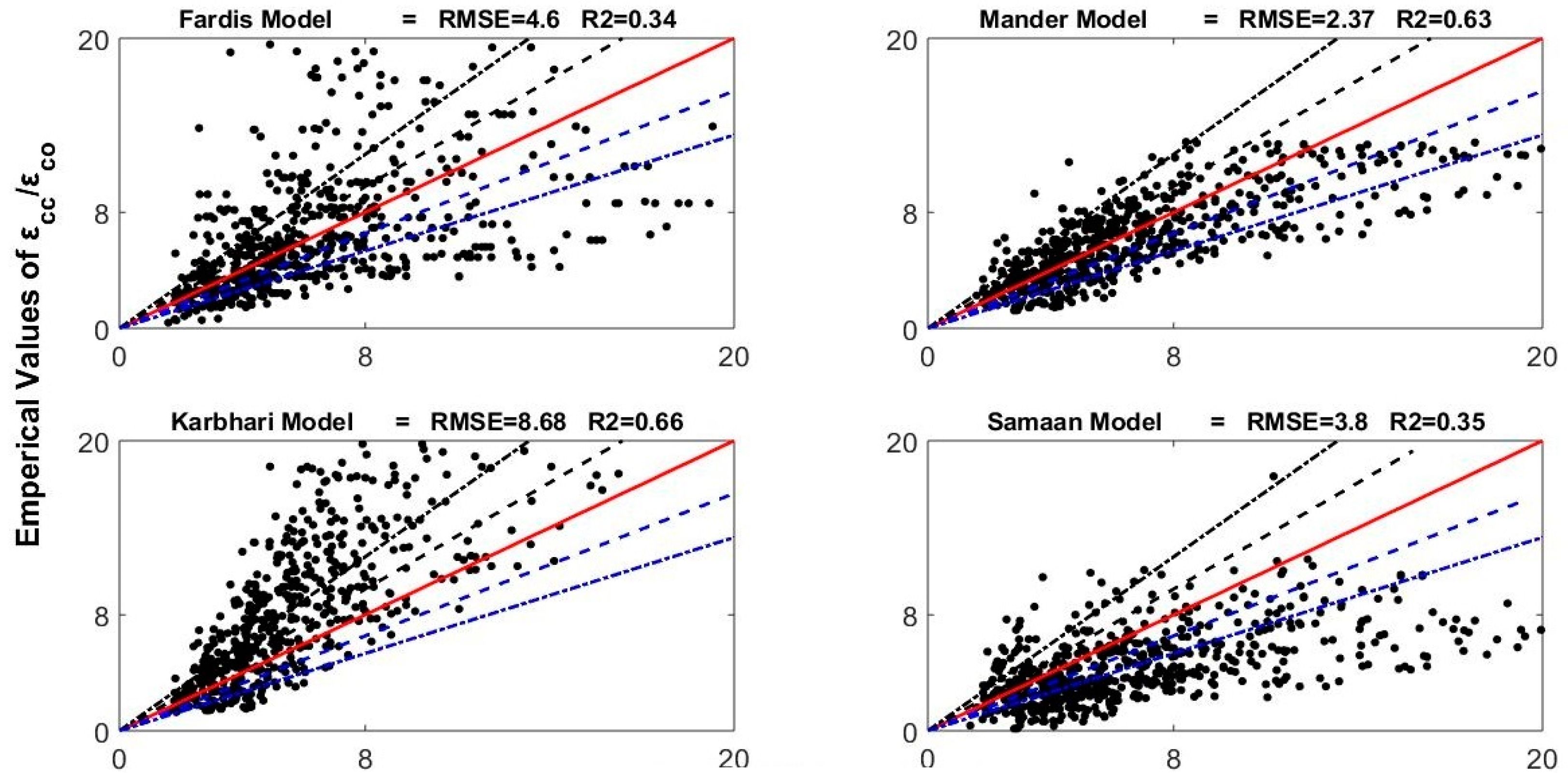
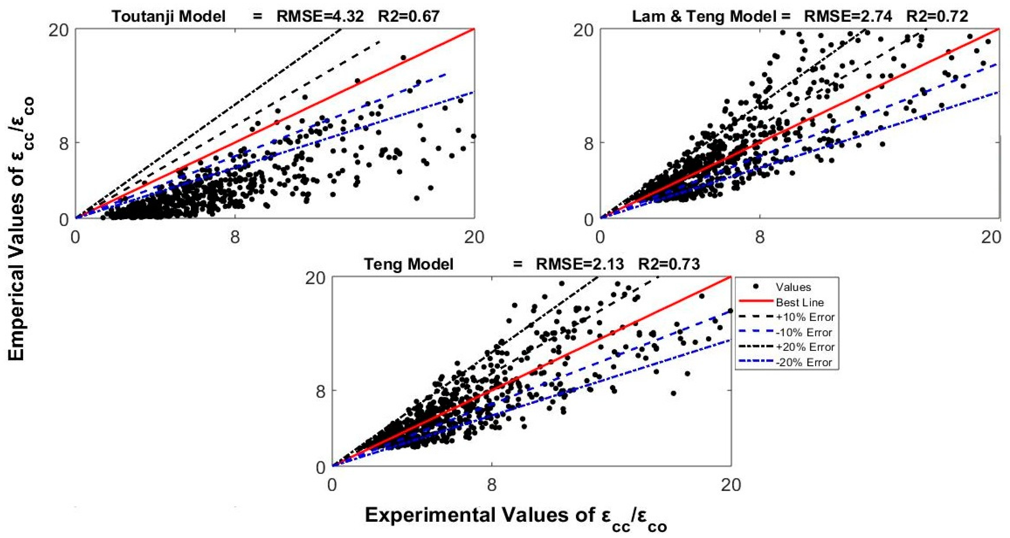
Where n is number of data points; x is the experimental value and y is the predicted value of confined concrete strain. The value of parameter RMSE varies from zero to one giving a perfect prediction at zero. Similarly, the value of parameter R2 also varies from zero to one; one shows a perfect correlation and zero represents that there is no correlation between experimental and predicted values of strains. The difference between experimental and predicted values was taken as error and SSE was minimized to achieve the best fit. A smaller value of SSE shows a tight fit of the empirical model to the experimental data. The performances of the previously proposed confined concrete strain models with R2 and RMSE were represented in Figure 2.

3.2. Evaluation of Models

The strain model proposed by Fardis and Khalili [15] represents the performance on the previous experimental database with R2 of 0.34 and RMSE of 4.6 which tell that the concept behind this model, i.e., the ultimate strain increases with the circumferential stiffness of confined concrete, was not accurate. Mander et al. [16] model shows the performance with R2 = 0.63 and RMSE = 2.37 which is a relatively good performance due to which this model was recommended by ACI 440-2R-02 [34]. Similarly, Karbhari and Gao [17] model shows the performance with R2 = 0.66 and RMSE = 8.68; Samaan et al. [18] model shows the performance with R2 = 0.35 and RMSE = 3.80; Toutanji [19] model shows the performance with R2 = 0.67 and RMSE = 4.32; Lam and Teng [20] model shows the performance with R2 = 0.72 and RMSE = 2.74 and Teng et al. [21] model shows the performance with R2 = 0.73 and RMSE = 2.13. These evaluations represent that the model proposed by Teng et al. [21] gave the best performance among the evaluated models. The values of R2 and RMSE for all the evaluated models were also presented in Table 3. Therefore, the general form of this model was selected as final for the current study as given by Equation (14). After determining the constants of the selected form of strain model, the proposed nonlinear analytical model for strain of FRP confined concrete is given by Equation (15).
ε c c / ε c o = α + β ρ k λ 1 ρ ε λ 2
where α , β , λ 1 and λ 2 are constants which were determined by using general regression analysis.
ε c c / ε c o = 1.85 + 7.46 ρ k 0.71 ρ ε 1.17
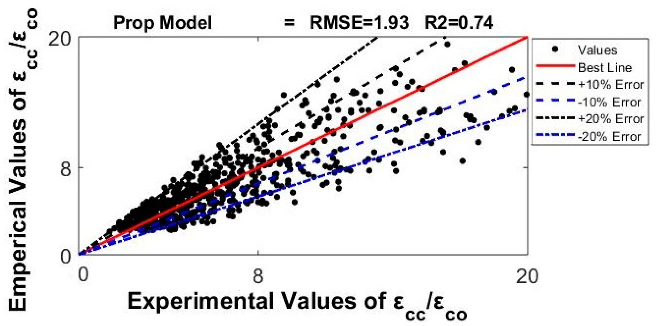
The performance of the proposed analytical strain model is given in Figure 3 using the database of 678 points with the R2 = 0.74 and RMSE = 1.93. These statistical indices show that the performance of currently proposed strain model is better than that of the previously proposed models with significant accuracy because the index of RMSE is less and index of R2 is higher for the proposed model which is desirable.
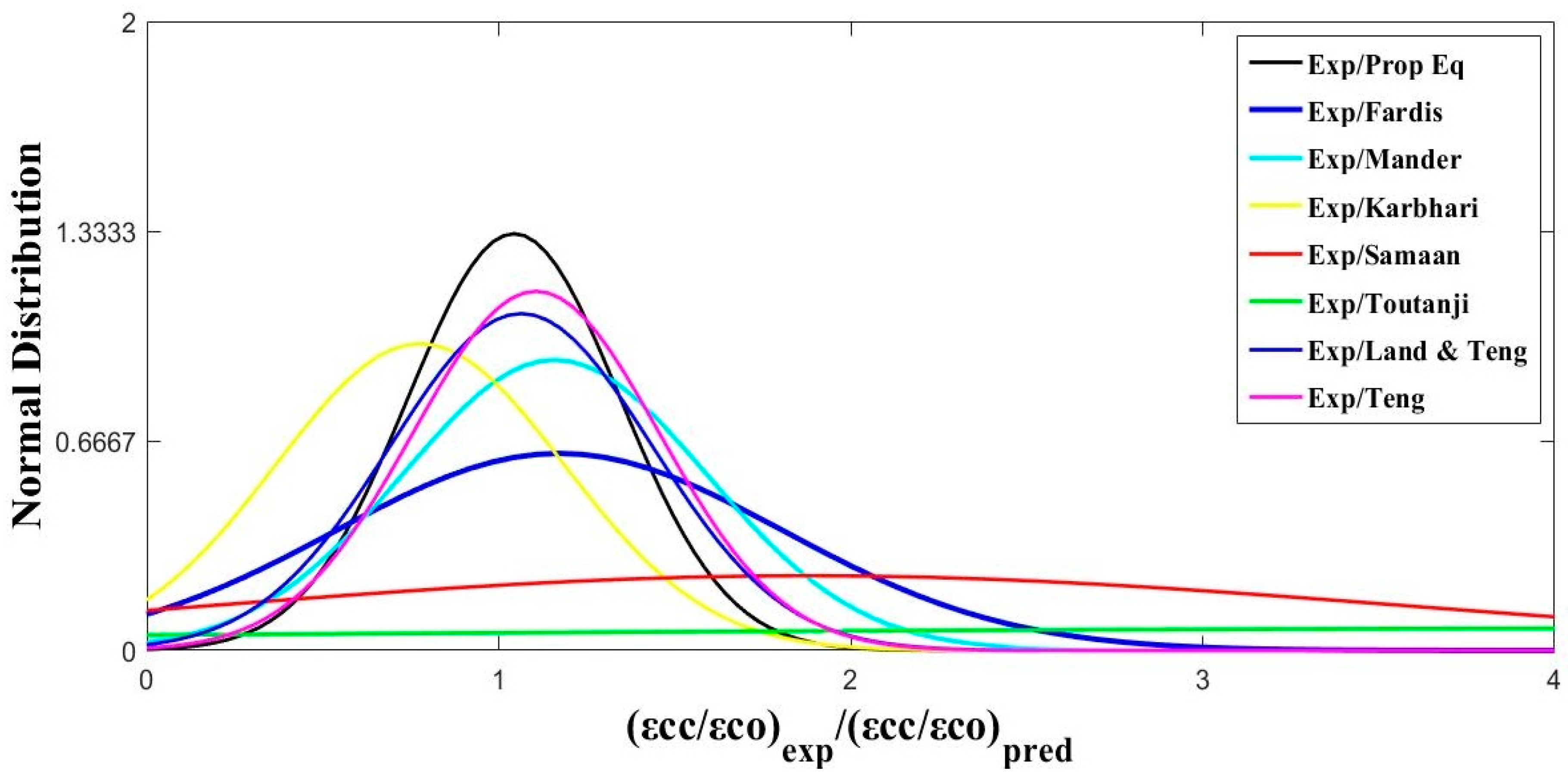
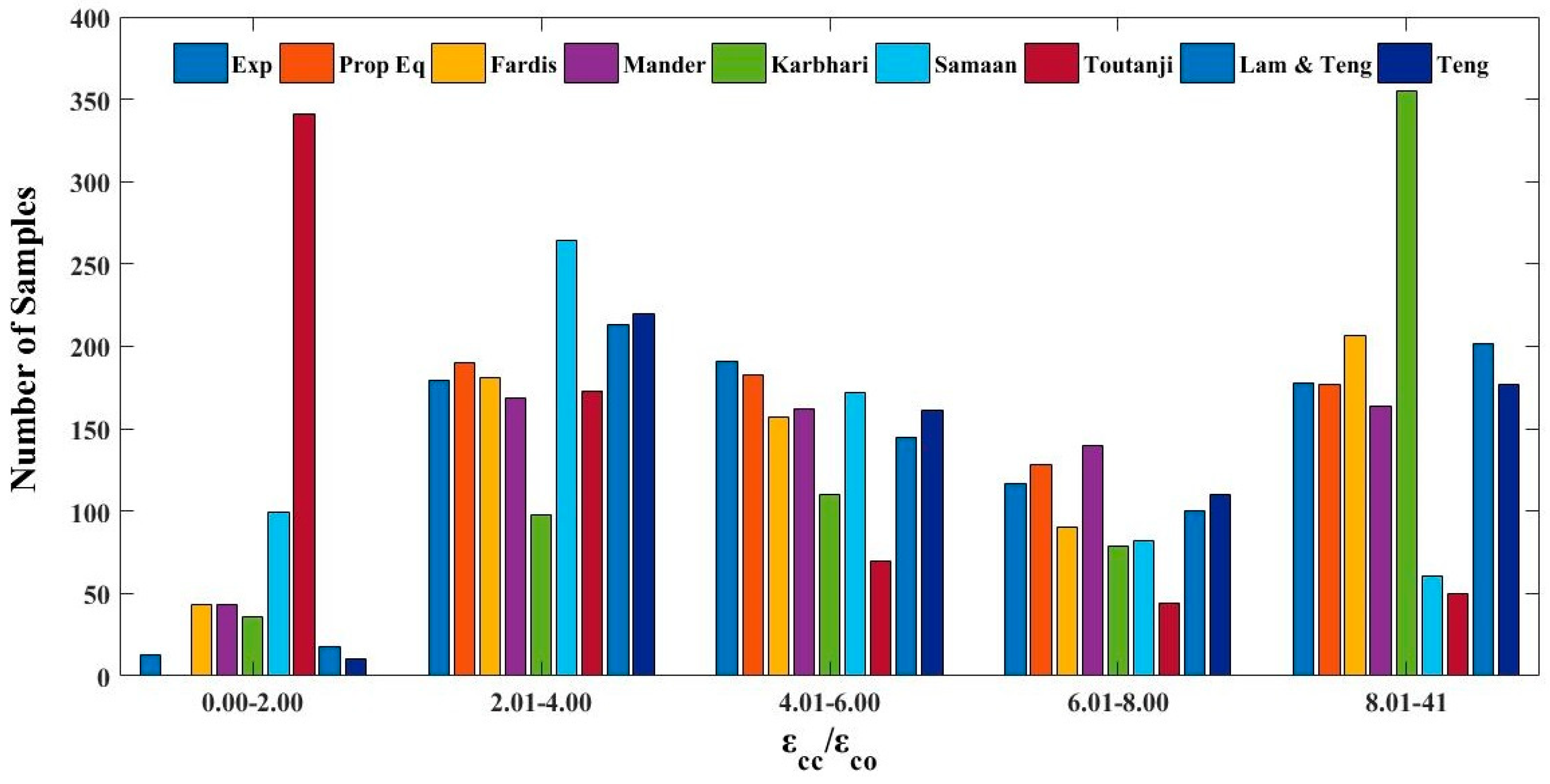
For a comparative study of the currently proposed and previously proposed strain models, the normal distribution curves and ratios of predictions were plotted. The normal distribution of confined concrete strains to unconfined concrete strains ratios of experimental predictions to theoretical predictions of different models for the previous database were presented by Figure 4 and the distribution of confined concrete strains to unconfined concrete strains ratios of the database was presented by Figure 5. The proposed analytical model and Lam and Teng [20] model performed well for the mean normalized values. The deviations of the proposed analytical model and Lam and Teng [20] model were 2.5% and 3% from unity, respectively. The normalized predictions of other previously proposed strain models were found to be conservative. It was observed that Toutanji [19] model presented most of ε c c / ε c o ratios in the range 0.0–2.0. Thus, the proposed strain models for confined concrete are capable of providing the accurate results for confined concrete strain as compared with previous models.
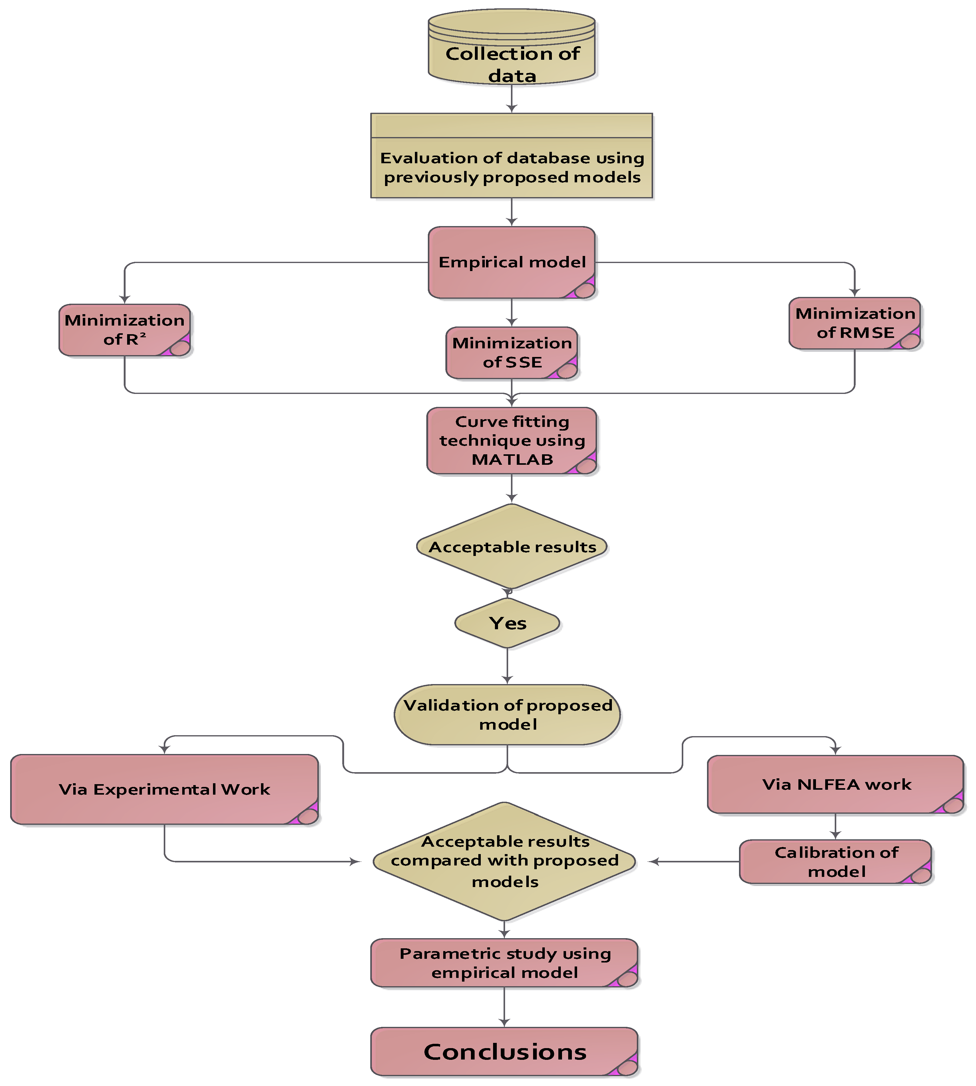
A general flow chart of the present work has been shown in Figure 6. A large experimental database of confined concrete strains was collected from literature and some preliminary evaluations were made on it using statistical indices such as R2, SSE, and RMSE. The analytical model was proposed using curve fittings in MATLAB by minimizing the error functions and by determining the constants.

4. Validation of Proposed Empirical Model

For the validation of proposed strain models, a nonlinear FEA work was performed for FRP confined concrete cylinders. The predictions of FEA model were compared with currently proposed and previous strain models.

4.1. Nonlinear Finite Element Analysis (NLFEA)

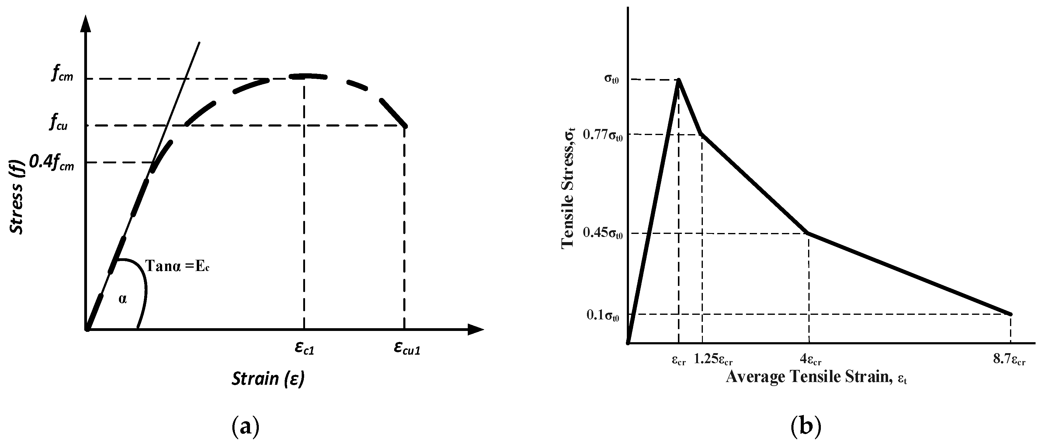
Numerical methods are more efficient and economical tools as compared with experiments for the structural analysis and engineering research [26]. These methods can save the cost and time by developing the numerical models that can capture the complex damage behavior accurately. The finite element modelling of cylinders confined with FRPs was done using the commercial software ABAQUS (version 6.14, Simulia corp., Providence, U.S, 2013). The results of proposed model were validated using the load-deflection curves from the literature [35]. A control cylinder was used to propose a numerical model after the calibration of different parameters such as dilation angle, viscosity parameter of concrete, mesh size and element types of the concrete. The behavior of concrete was simulated by using concrete damaged plasticity (CDP) model and FRP wraps were simulated using Hashin’s damage model [36,37]. To define the contact between concrete column and FRP sheets, a perfect bond was defined by applying “tie” constraint between them. The accurate definition of the bonding behavior between the FRP sheets and concrete is very important for the precise predictions [38,39]. The boundary conditions and meshing used in the numerical model of cylinder were presented in Figure 7. The bottom end of cylinders was fixed for displacements and rotations in all directions and displacement control technique was used for the application of load on the top surface. During the calibration process of finite element model, the default values for shape factor Kc = 0.667, for eccentricity = 0.1 and for compressive stresses ratios = 1.16 were taken to define the plastic behavior of concrete in ABAQUS. The compressive behavior as shown in Figure 8a, was used for concrete in the present study. The linear elastic behavior of concrete may be taken up to 0.4 fcm [40]. The relations proposed by [41] were used to find the average compressive strain εc1 and the ultimate strain εcu1 of the concrete as presented by Equations (16) and (17).
ε c 1 = 0.0014 [ 2 e 0.024 f c m e 0.140 f c m ]
ε c u 1 = 0.004 0.0011 [ 1 e 0.0215 f c m ]
To define the stress-strain relationship of concrete, the model given by Eurocode [42] was used given by Equation (18).
σ c = f c m k η η 2 1 + ( k 2 ) η
where,
k = 1.05 E c m ε c 1 f c m ,   η = ε c ε c 1
The tensile behavior of concrete was defined by modified tension stiffening model [43] (see Figure 8b).
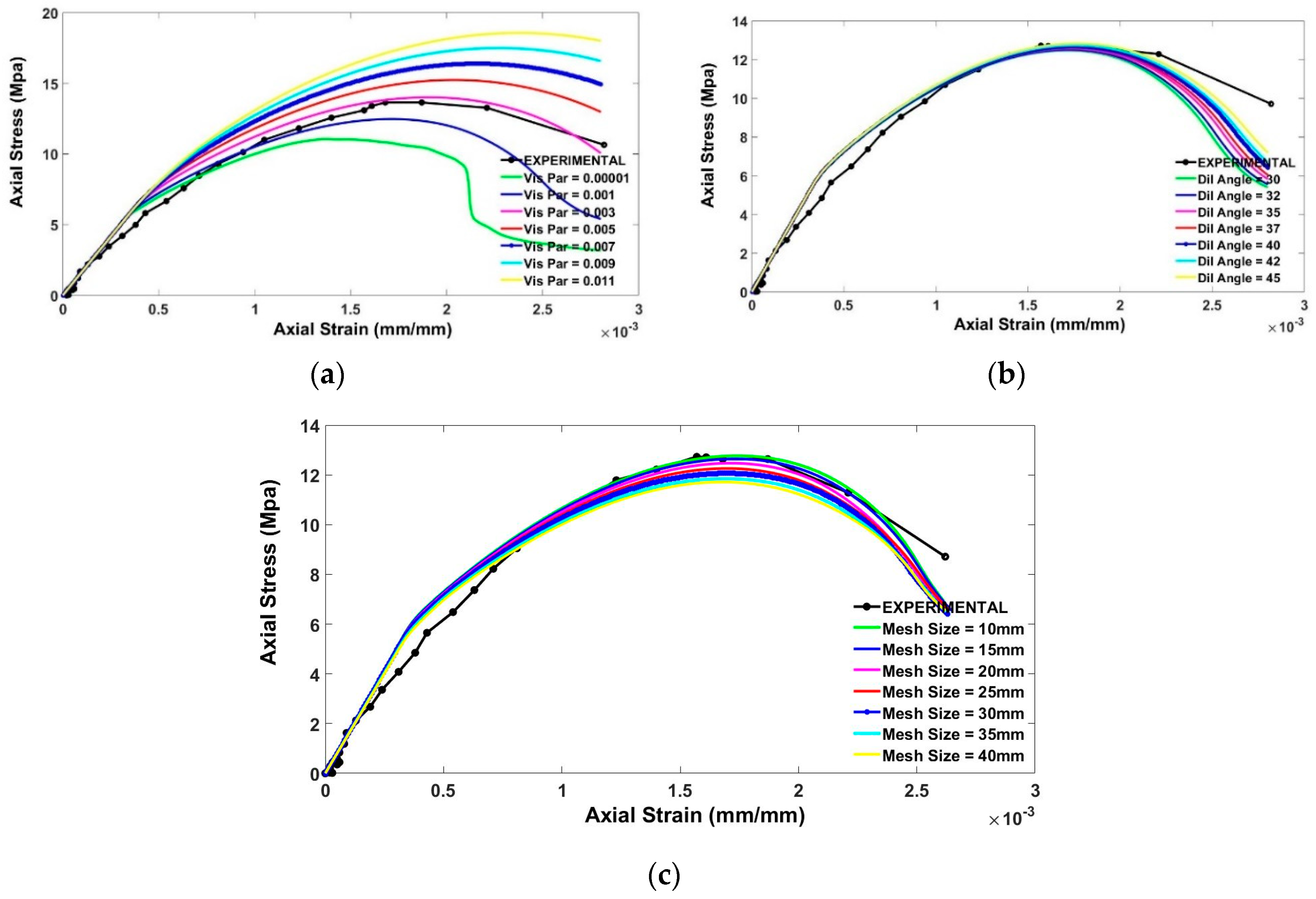
A control model was selected for the calibration purpose having a single layer of FRP material with compressive strength of 12.5 MPa. Firstly, the selected concrete cylinder was calibrated to achieve a reliable finite element model (FEM) in which the numerical results of stress-strain are in close agreement with experimental results and then, this calibrated model was utilized for the simulations of all FRP-wrapped cylinders. Various viscosity parameters of 0.00001, 0.0010, 0.0030, 0.0055, 0.0070, 0.0090 and 0.0110 were studied to predict the effect of this parameter on the stress-strain behavior of concrete. A viscosity parameter of 0.0055 gave the best approximation for the stress-strain behavior of plain concrete and hence, this value was selected for the viscosity parameter of concrete in the current work.
The effect of dilation angle, viscosity parameter and mesh size of concrete are shown in Figure 9. The experimental peak value of stress was 12.5 MPa at a strain of 0.0017. From the first subplot of Figure 9, it can be examined that the peak stress value matches the experimental value when the values of the viscosity parameter and dilation angle are 0.0055 and 30°, respectively. For dilation angle, the Drucker–Prager plastic potential function was used as given by Equation (20).
G ( σ ) = ( ε σ t o t a n ψ ) 2 + q ¯ 2 + 1 3 I 1 t a n ψ
where, α p is the dilatancy parameter according to Lee and Fenves [44] having a value of 0.2, for which the dilation angle should be near to 30°. After the calibration for dilation angle of concrete, the value of 30° gave the best approximation as compared with the previous experimental stress–strain results of the control specimen.
The numerical model of the control cylinder presented here is highly depending upon the mesh size because of the strain localization phenomena. To achieve better results of control specimen in terms of load-deflection curve, it is important to use smaller mesh size but not enough smaller to enhance the analysis time and burden of computer to solve the equations formed by the FEA procedure. Different mesh sizes ranging from 10 mm to 40 mm were used to see the effect of the variation of the mesh size dependency but found better results at mesh size of 20 mm. From Figure 9, a close agreement with experimental stress was achieved when the mesh size of 20 mm was used with the viscosity parameter of 0.0055 and dilation angle of 30°. Similarly, it can be observed that the strain of 0.0017 was achieved by using viscosity parameter, dilation angle and mesh size of 0.0055, 30° and 20 mm at the same time, respectively.
The influence variation of stress ratio, eccentricity and shape factor for the plastic behavior of concrete in CDP model was also investigated but their effect on stress-strain behavior of cylinders was negligible. Thus, the default values, i.e., Kc = 0.667, ε = 0.1 and σ b 0 / σ c 0 = 1.16 were used. The effect of different element types of concrete was also studied in this research. All the element library of ABAQUS for the 3D stress elements of concrete was studied to check the effects of elements types of concrete. The hexahedral, tetrahedral and triangular elements with different formulations were analyzed giving the best approximate at C3D8R elements.
For the simulations of FRP sheets, the Hashin damage model was used. The FRP material can be considered as a 2D filament object having different moduli of elasticity in longitudinal and transverse directions and its behavior can be defined by two stages: the first is elastic stage defined by modulus of elasticity and Poisson’s ratio as shown in Table 4 and the second is the plastic stage which is defined by Hashin’s [37] failure model. ABAQUS Standard follows the Hashin’s theory [36,37] for the prediction of damage criterion of FRPs using four damage mechanisms which are fiber tension and compression and matrix tension and compression. The failure of FRP resulting due to shear can be defined by Equation (21) as presented by [45]:
γ x y = G x y 1 σ x y + α σ x y 3
where, γ x y is shear strain in x-y plain, Gxy is the shear modulus of elasticity of FRP and α is the nonlinearity factor having a value of 55 × 10−5 MPa−3. The different variables for the Hashin damage model are given in Table 5. The strength properties in the transverse direction were taken as small values compared with the properties in longitudinal direction [30].

4.2. Discussion of Results

Figure 10 shows the compressive strengths and strains of unconfined and confined concrete cylinders tested in the previous study [35]. The average stress-strain curves of experimental cylinders were plotted against the FEA results.
The experimental results confirmed the increase in strength and ductility with the increasing number of FRP layers. It was observed that the increase of 69.42% and 87.20% occurred in axial strength of confined concrete of 12.5 MPa strength for single and double wraps of FRP, respectively and an increase of 60.82% and 103.20% occurred for 16.5 MPa concrete with single and double wraps of FRP, respectively as compared with plain concrete specimens. Similarly, the axial strain of cylinders was increased by 409.26% and 277.78% using single layer of FRP and 464.81% and 459.72% using double layer of FRP with 12.5 MPa and 16.5 MPa, respectively. This discussion shows that the confinement is effective in low strength concrete for both strength and ductility of concrete.
The average percentage discrepancies between the experimental and FEA results of FRP confined concrete cylinders were 14.93% and 16.93% for axial strength and axial strain, respectively. These discrepancies may be due to the minor inaccuracies due to the difference between actual and testing and boundary conditions, assumptions made during FEA and the accuracy of the testing instruments. However, the overall experimental stress-strain curves of all the cylinders were predicted accurately by the FEA results showing that the selected constitutive FEA model can be utilized for the simulations of FRP-confined concrete.
The crack patterns of some specimens obtained from FEA results are shown in Figure 11. The finite element crack patterns were represented through maximum principal plastic strains because the concrete damaged plasticity model (CDPM) assumes that the cracks in the concrete start when there is a positive value of maximum principal plastic strain. The FEA cracks in concrete can also be represented by tensile principal stresses [2,46]. Figure 11 represents the cracking patterns of a plain concrete cylinder, a double-layered FRP cylinder with strength of 12.5 MPa and two cylinders with single and double layers of FRP sheets having the concrete strength of 16.5 MPa. It can be visualized that the FEA crack patterns are in a close agreement with the experimental cracks proving that the FEA software ABAQUS accurately predicted the behavior of FRP-wrapped concrete. The FEA cracks decrease with less expansion of concrete cylinders as the confinement thickness increases which is experimentally true.
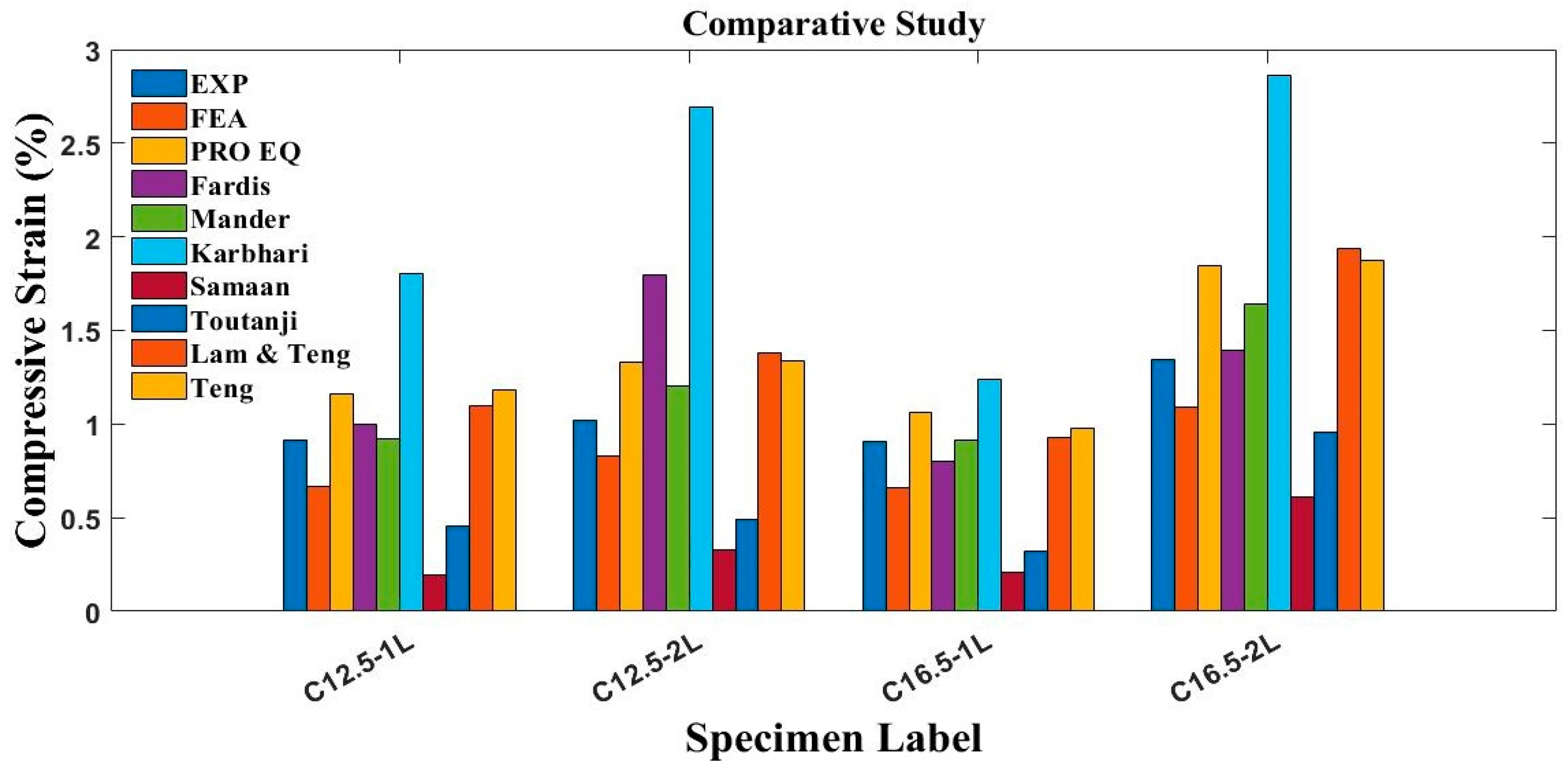
The average percentage discrepancies of the predictions of proposed empirical strain model from experimental and FEA results were 13.51% and 37.81%, respectively, which shows that the proposed model can predict the strain of FRP-confined concrete. All the results for compressive strains of confined concrete obtained from previously proposed empirical models, present experimental measurements, numerical and empirical predictions are presented in Figure 12.
The percentage discrepancies of strain models proposed by Fardis and Khalili [15], Mander et al. [16], Karbhari and Gao [17], Samaan et al. [18], Toutanji [19], Lam and Teng [20] and Teng et al. [21] from the experimental results were 25.34%, 10.07%, 103.01%, 3.80%, 16.47%, 25.61%, and 27.00%, respectively. It can be visualized that the proposed analytical equation is giving more precise predictions in comparison with experiments as discussed in the previous section. The maximum error was represented by Karbhari and Gao [17] model with a discrepancy of 103.01%. This discrepancy may be due to the reason that this model does not capture the true behavior of composite concrete and considers the constant confinement level without confinement jackets. Moreover, this model was proposed on the wrong assumption that the FRP material can reach its maximum tensile strength in the transverse direction.

5. Parametric Studies

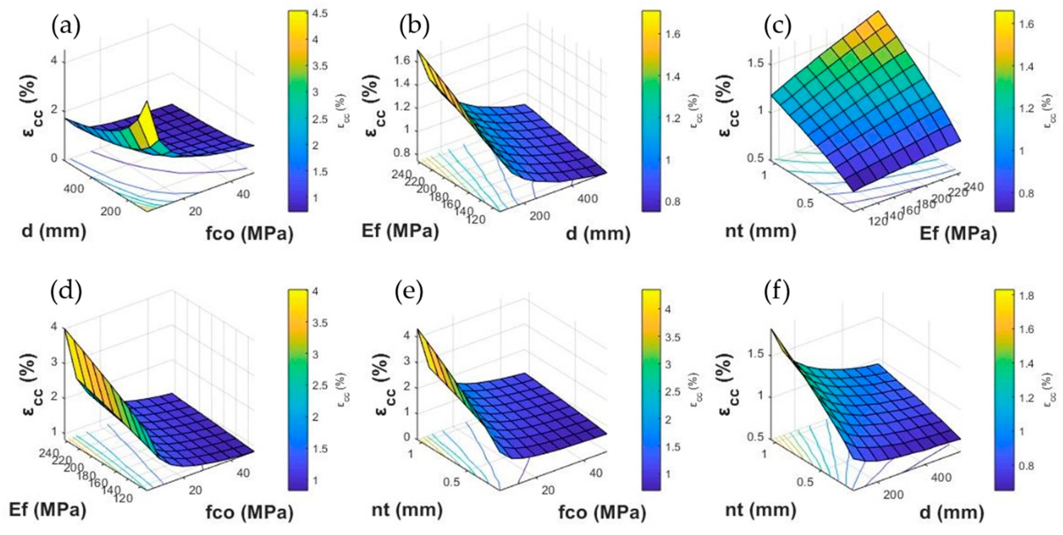
An extensive parametric study was performed by using the proposed empirical model to investigate the effects of the parameters including (a) unconfined concrete strength, (b) elastic modulus of FRP, (c) diameter of concrete cylinders and (d) total thickness of FRPs layers. For the study of each parameter, the objective is to see the effect of that parameter on axial strain of confined concrete. The constant and varying values of the studied parameters are shown in Table 6. The effect of any two parameters was observed at a time in three-dimensional plots while keeping the other parameters constant as shown in Figure 13.

5.1. Effect of Concrete Compressive Strength ( f c o )

The different values of unconfined concrete strengths ( f c o ) being used for the parametric study are 5 MPa to 50 MPa at an increment of 5 MPa. The effect of f c o variation is shown in Figure 13a,d,e. It was noted that when f c o increases from 5 MPa to 50 MPa and diameter of cylinder (d) increases from 100 mm to 550 mm at constant thickness (nt) and elastic modulus of fibers (Ef), the confined strain ( ε c c ) using the proposed model increases by 84.14%. When the elastic modulus of FRP increases from 110 GPa to 245 GPa at same increment of f c o , the ε c c of concrete increases by 58.57%. Similarly, when the f c o increases from 5 MPa to 50 MPa with the increase of fiber thickness from 0.15 mm to 1.05 mm, an increase of 28.48% takes place in the ε c c . This section shows that the effect of increment of f c o is more dominant when the diameter of specimen is increased. The hoop rupture strain of cylinders was determined using Equation (4) [33].

5.2. Effect of Cylinder Diameter (d)

The diameters of concrete cylinders used for the parametric study are from 100 mm to 550 mm at an increment of 50 mm. The variation of ε c c due to the increase of concrete diameter (d) is presented in Figure 13a,b,f. It can be observed that the ε c c of concrete increases up to 84.14% when f c o increases from 5 MPa to 50 Mpa and d increases from 100 mm to 550 mm at constant Ef and nt. When d increases from 100 mm to 550 mm with an increase of Ef from 110 GPa to 245 Gpa, the decrement of 25.62% occurred in ε c c . Therefore, it can be visualized that at lower diameters, the effect of Ef on ε c c is significant. Similarly, when the thickness of FRP increases from 0.15 mm to 1.05 mm at the same increase of d, an increase of only 6.82% occurred. However, at lower d, the effect of increasing the thickness of FRP is more significant.

5.3. Effect of Elastic Modulus of FRP (Ef)

The effect of variations of Ef is shown in Figure 13b–d. The different values used for the Ef are 110 GPa to 245 GPa at an increment of 15 GPa. When the Ef increases from 110 GPa to 245 GPa with an increase of d from 100 mm to 550 mm, ε c c increases by 25.62%. Similarly, when Ef increases from 110 GPa to 245 GPa and thickness of FRP increases from 0.15 mm to 1.05 mm, the increment in ε c c was 133.80%. The combined effect of Ef and f c o was shown in Figure 13d, which represents that the increase of 58.57% occurred due to increase of Ef from initial to final value with an increase of 50 MPa in f c o . This study concludes that the effect of increment of Ef is more significant for ε c c with the increase of nt.

5.4. Effect of Thickness of FRP Layers (nt)

The range of thickness of FRP layers was 0.15 mm to 1.05 mm at an increment of 0.10 mm. The effect of variations of thickness of FRP layers is shown in Figure 13c,e,f. When nt increases from 0.15 mm to 1.05 mm and Ef increases from 110 GPa to 245 GPa, the increment in ε c c was up to 133.80%. When nt increases from 0.15 mm to 1.05 mm with an increase of 50 MPa in f c o , 28.48% increase in the ε c c occurred showing that the effect of increasing the nt is more significant at higher values of f c o . Similarly, the effect of increasing the nt at larger diameters of concrete was negligible, but at lower values of diameter, the effect of increment of nt on ε c c was significant as presented in Figure 13f.
In general, by increasing the unconfined concrete strength ( f c o ) , the confined concrete strain ( ε c c ) increases slightly and by increasing the thickness of FRP (nt), there is a significant increase in ε c c . Similarly, the effect of the increase of elastic modulus of FRP (Ef) on ε c c is significant. However, the effect of increasing the diameter of concrete (d) was opposite. At lower values of diameter, the value of ε c c was higher.

6. Conclusions

The present study aims to evaluate the effectiveness and reliability of FRP wrapping on plain concrete and to propose the FEA and empirical models for predicting the axial compressive strain of FRP confined concrete. The main conclusions derived from the present study work are as given:
  • The proposed analytical strain model performed well in the previous experimental database of 678 samples with R2 = 0.74 and RMSE = 1.93. Thus, the performance of proposed model on the previous experimental database shows its superiority over the previous models.
  • The FEA performed in the present study shows that the average percentage discrepancies between previous experimental and current FEA results for FRP confined concrete cylinders were 14.93% and 13.88% for strength and strain, respectively. It shows that the finite element (FE) model traced the experimental behavior of FRP-confined concrete accurately.
  • The average percentage discrepancy for axial strain between the previous experimental and proposed empirical model results was only 13.51%. Similarly, the average percentage discrepancy for axial strain between present NLFEA and proposed empirical model results was only 37.81%. Thus, the proposed empirical model for confined concrete strains was in a close agreement for performance with the experimental and NLFEA results.
  • The parametric study using the proposed empirical model concluded that the axial confined strain of concrete increases with the increase of unconfined strength and thickness of FRP layers and its elastic modulus, while no significant effect was observed for increasing the core diameter of concrete.
  • From the comparisons of this study, it can be concluded that the proposed empirical and FEA models can predict the axial strain of FRP-confined concrete with accuracy and are helpful for engineers in analyzing and designing the FRP-confined concrete compression members.

Author Contributions

Conceptualization, A.R. and S.A.R.S.; formal analysis, A.R.K.; methodology, A.R., M.A.A. and T.A.K.; validation, S.H., A.S. and K.A.; visualization, A.R.K.; writing—original draft, A.R. and S.A.R.S.; writing—review and editing, G.S. and M.W. All authors have read and agreed to the published version of the manuscript.

Funding

This research received no external funding.

Conflicts of Interest

The authors declare no conflict of interest.

References

  1. Hollaway, L.C.; Chryssanthopoulos, M.; Moy, S.S. Advanced Polymer Composites for Structural Applications in Construction: ACIC 2004; Woodhead Publishing: Sawston, UK, 2004; Volume 1, pp. 771–772. [Google Scholar]
  2. Raza, A.; Khan, Q.U.Z.; Ahmad, A. Numerical investigation of load-carrying capacity of GFRP-reinforced rectangular concrete members using CDP model in ABAQUS. Adv. Civ. Eng. 2019, 2019. [Google Scholar] [CrossRef] [Green Version]
  3. Parvin, A.; Jamwal, A.S. Effects of wrap thickness and ply configuration on composite-confined concrete cylinders. Compos. Struct. 2005, 67, 437–442. [Google Scholar] [CrossRef]
  4. Li, G.; Kidane, S.; Pang, S.-S.; Helms, J.E.; Stubblefield, M.A. Investigation into FRP repaired RC columns. Compos. Struct. 2003, 62, 83–89. [Google Scholar] [CrossRef]
  5. Demers, M.; Neale, K.W. Confinement of reinforced concrete columns with fibre-reinforced composite sheets-an experimental study. Can. J. Civ. Eng. 1999, 26, 226–241. [Google Scholar] [CrossRef]
  6. Prota, A.; Manfredi, G.; Cosenza, E. Ultimate behavior of axially loaded RC wall-like columns confined with GFRP. Compos. B Eng. 2006, 37, 670–678. [Google Scholar] [CrossRef]
  7. Li, L.J.; Guo, Y.C.; Liu, F.; Bungey, J.H. An experimental and numerical study of the effect of thickness and length of CFRP on performance of repaired reinforced concrete beams. Constr. Build. Mater. 2006, 20, 901–909. [Google Scholar] [CrossRef]
  8. Li, G.; Maricherla, D.; Singh, K.; Pang, S.S.; John, M. Effect of fiber orientation on the structural behavior of FRP wrapped concrete cylinders. Compos. Struct. 2006, 74, 475–483. [Google Scholar] [CrossRef]
  9. Ţăranu, N.; Oprişan, G.; Enţuc, I.; Munteanu, V.; Cozmanciuc, C. The Efficiency of Fiber Reinforced Polymer Composites Solutions in the Construction Industry. In Proceedings of the 6th International Conference on Management of Technological Changes, MTC, Alexandroupolis, Greece, January 2009; pp. 733–736. [Google Scholar]
  10. De Lorenzis, L.; Tepfers, R. Comparative study of models on confinement of concrete cylinders with fiber-reinforced polymer composites. J. Compos. Constr. 2003, 7, 219–237. [Google Scholar] [CrossRef]
  11. Kawashima, K.; Koyama, T. Effects of cyclic loding hysteresis on dynamic behavior of reinforced concrete bridge piers. Doboku Gakkai Ronbunshu 1988, 1988, 139–146. [Google Scholar] [CrossRef] [Green Version]
  12. Hoshikuma, J.; Kawashima, K.; Nagaya, K.; Taylor, A.W. Stress-strain model for confined reinforced concrete in bridge piers. J. Struct. Eng.-Asce. 1997, 123, 624–633. [Google Scholar] [CrossRef]
  13. Kawashima, K.; Shoji, G.; Sakakibara, Y. A cyclic loading test for clarifying the plastic hinge length of reinforced concrete piers. J. Struct. Eng.-Asce. 2000, 46, 767–776. [Google Scholar]
  14. Ann, K.; Cho, C.-G. Constitutive behavior and finite element analysis of FRP composite and concrete members. Materials 2013, 6, 3978–3988. [Google Scholar] [CrossRef] [PubMed] [Green Version]
  15. Fardis, M.N.; Khalili, H.H. FRP-encased concrete as a structural material. Mag. Concrete Res. 1982, 34, 191–202. [Google Scholar] [CrossRef]
  16. Mander, J.B.; Priestley, M.J.; Park, R. Theoretical stress-strain model for confined concrete. J. Struct. Eng.-Asce. 1988, 114, 1804–1826. [Google Scholar] [CrossRef] [Green Version]
  17. Karbhari, V.M.; Gao, Y. Composite jacketed concrete under uniaxial compression—Verification of simple design equations. J. Mater. Civ. Eng. 1997, 9, 185–193. [Google Scholar] [CrossRef]
  18. Samaan, M.; Mirmiran, A.; Shahawy, M. Model of concrete confined by fiber composites. J. Struct. Eng.-Asce. 1998, 124, 1025–1031. [Google Scholar] [CrossRef]
  19. Toutanji, H. Stress-strain characteristics of concrete columns externally confined with advanced fiber composite sheets. ACI Mater. J. 1999, 96, 397–404. [Google Scholar]
  20. Lam, L.; Teng, J. Design-oriented stress–strain model for FRP-confined concrete. Constr. Build. Mater. 2003, 17, 471–489. [Google Scholar] [CrossRef]
  21. Teng, J.G.; Yu, T.; Wong, Y.L.; Dong, S.L. Hybrid FRP–concrete–steel tubular columns: Concept and behavior. Constr. Build. Mater. 2007, 21, 846–854. [Google Scholar] [CrossRef]
  22. Miyauchi, K.; Inoue, S.; Kuroda, T.; Kobayashi, A. Strengthening effects of concrete column with carbon fiber sheet. Trans. Jpn. Concr. Inst. 2000, 21, 143–150. [Google Scholar]
  23. Bisby, L.A.; Dent, A.J.S.; Green, M.F. Comparison of confinement models for fiber-reinforced polymer-wrapped concrete. ACI Struct. J. 2005, 102, 62–72. [Google Scholar]
  24. Matthys, S.; Toutanji, H.; Audenaert, K.; Taerwe, L. Axial load behavior of large-scale columns confined with fiber-reinforced polymer composites. ACI Struct. J. 2005, 102, 258. [Google Scholar]
  25. Shi, Y.; Swait, T.; Soutis, C. Modelling damage evolution in composite laminates subjected to low velocity impact. Compos. Struct. 2012, 94, 2902–2913. [Google Scholar] [CrossRef]
  26. Matthews, F.L.; Davies, G.; Hitchings, D.; Soutis, C. Finite Element Modelling of Composite Materials and Structures; CRC Press: Boston, MA, USA; New York, NY, USA; Washington, DC, USA, 2000; pp. 1–52. [Google Scholar]
  27. Ribeiro, F.; Sena-Cruz, J.; Branco, F.G.; Júlio, E. 3D finite element model for hybrid FRP-confined concrete in compression using modified CDPM. Eng. Struct. 2019, 190, 459–479. [Google Scholar] [CrossRef]
  28. Piscesa, B.; Attard, M.M.; Samani, A.K. 3D Finite element modeling of circular reinforced concrete columns confined with FRP using a plasticity based formulation. Compos. Struct. 2018, 194, 478–493. [Google Scholar] [CrossRef]
  29. Lo, S.; Kwan, A.K.H.; Ouyang, Y.; Ho, J.C.M. Finite element analysis of axially loaded FRP-confined rectangular concrete columns. Eng. Struct. 2015, 100, 253–263. [Google Scholar] [CrossRef]
  30. Hany, N.F.; Hantouche, E.G.; Harajli, M.H. Finite element modeling of FRP-confined concrete using modified concrete damaged plasticity. Eng. Struct. 2016, 125, 1–14. [Google Scholar] [CrossRef]
  31. Ferrotto, M.; Fischer, O.; Cavaleri, L. A strategy for the finite element modeling of FRP-confined concrete columns subjected to preload. Eng. Struct. 2018, 173, 1054–1067. [Google Scholar] [CrossRef]
  32. Teng, J.G.; Jiang, T.; Lam, L.; Luo, Y.Z. Refinement of a design-oriented stress–strain model for FRP-confined concrete. J. Compos. Constr. 2009, 13, 269–278. [Google Scholar] [CrossRef] [Green Version]
  33. Lim, J.C.; Karakus, M.; Ozbakkaloglu, T. Evaluation of ultimate conditions of FRP-confined concrete columns using genetic programming. Comput. Struct. 2016, 162, 28–37. [Google Scholar] [CrossRef]
  34. Bakis, C.E.; Ganjehlou, A.; Kachlakev, D.I.; Schupack, M.; Balaguru, P.N.; Gee, D.J.; Karbhari, V.M.; Scott, D.W.; Ballinger, C.A.; Gentry, T.R.; et al. Guide for the design and construction of externally bonded FRP systems for strengthening concrete structures. ACI Committee Rep. 2002, 440.2R-1–440.2R-45. [Google Scholar]
  35. Saeed, H.Z.; Khan, Q.U.Z.; Khan, H.A.; Farooq, R. Experimental investigation of stress–strain behavior of CFRP confined Low Strength Concrete (LSC) cylinders. Constr. Build. Mater. 2016, 104, 208–215. [Google Scholar] [CrossRef]
  36. Hashin, Z.; Rotem, A. A fatigue failure criterion for fiber reinforced materials. J. Compos. Mater. 1973, 7, 448–464. [Google Scholar] [CrossRef] [Green Version]
  37. Hashin, Z. Failure criteria for unidirectional fiber composites. J. Appl. Mech. 1980, 47, 329–334. [Google Scholar] [CrossRef]
  38. Cascardi, A.; Micelli, F.; Aiello, M.A. Unified model for hollow columns externally confined by FRP. Eng. Struct. 2016, 111, 119–130. [Google Scholar] [CrossRef]
  39. Monaldo, E.; Nerilli, F.; Vairo, G. Effectiveness of some technical standards for debonding analysis in FRP-concrete systems. Compos. B Eng. 2019, 160, 254–267. [Google Scholar] [CrossRef]
  40. Kmiecik, P.; Kamiński, M. Modelling of reinforced concrete structures and composite structures with concrete strength degradation taken into consideration. Arch. Civ. Mech. Eng. 2011, 11, 623–636. [Google Scholar] [CrossRef]
  41. Majewski, S. The Mechanics of Structural Concrete in Terms of Elasto-Plasticity; Publishing House of Silesian University of Technology: Gliwice, Poland, 2003. [Google Scholar]
  42. De Normalisation, C.E.J.B. Belgium, Eurocode 2: Design of Concrete Structures—Part 1-1: General Rules and Rules for Buildings. 2004. Available online: https://www.phd.eng.br/wp-content/uploads/2015/12/en.1992.1.1.2004.pdf (accessed on 31 December 2019).
  43. Wahalathantri, B.L.; Thambiratnam, D.P.; Chan, T.H.T.; Fawzia, S. A material model for flexural crack simulation in reinforced concrete elements using ABAQUS. In Proceedings of the First International Conference on Engineering, Designing and Developing the Built Environment for Sustainable Wellbeing, Queensland University of Technology, Brisbane, Australia, April 2011; pp. 260–264. [Google Scholar]
  44. Lee, J.; Fenves, G.L. Plastic-damage model for cyclic loading of concrete structures. J. Eng. Mech. 1998, 124, 892–900. [Google Scholar] [CrossRef]
  45. Lessard, L.B.; Chang, F.K. Damage tolerance of laminated composites containing an open hole and subjected to compressive loadings: Part II—Experiment. J. Compos. Mater. 1991, 25, 44–64. [Google Scholar] [CrossRef]
  46. Genikomsou, A.S.; Polak, M.A. Finite element analysis of punching shear of concrete slabs using damaged plasticity model in ABAQUS. Eng. Struct. 2015, 98, 38–48. [Google Scholar] [CrossRef]
Figure 1. Confinement mechanics of fiber-reinforced polymer (FRP) sheets.
Applsci 10 00333 g001
Figure 2. Performance of previously proposed and presently proposed strain models of confined concrete on the developed database.
Applsci 10 00333 g002aApplsci 10 00333 g002b
Figure 3. Performance of proposed empirical models of confined concrete.
Applsci 10 00333 g003
Figure 4. Normal distribution of ( ε c c / ε c o e x p ) / ( ε c c / ε c o p r e d ) for FRP-wrapped cylinders based on predictions of various strain models.
Applsci 10 00333 g004
Figure 5. Distribution of ε c c / ε c o for FRP-wrapped cylinders based on predictions of various strain models.
Applsci 10 00333 g005
Figure 6. Flow chart of the present research work.
Applsci 10 00333 g006
Figure 7. Geometry and boundary conditions of cylinders: (a) rigid body surfaces, (b) tie constraint between FRP and concrete, (c) loading and boundary conditions, (d) meshing.
Applsci 10 00333 g007
Figure 8. (a) Stress-strain curve for reinforced concrete given by Euro code [42] and (b) modified tension stiffening model.
Applsci 10 00333 g008
Figure 9. Effect of (a) viscosity parameter, (b) dilation angle and (c) mesh size on stress–strain behavior of control cylinder specimen (C12.5-1L).
Applsci 10 00333 g009
Figure 10. Stress-strain curves of (a) unconfined concrete cylinder and (bf) confined concrete cylinders.
Applsci 10 00333 g010
Figure 11. Crack patterns of tested specimens in ABAQUS.
Applsci 10 00333 g011
Figure 12. Performance of previous and currently proposed strain models on the experimental results of confined concrete cylinders.
Applsci 10 00333 g012
Figure 13. Parametric studies using proposed strain model.
Applsci 10 00333 g013
Table 1. Previous strain models for confined concrete.
ModelExpression for Strain of Confined Concrete
Fardis and Khalili [15] model ε c c = 0.002 + 0.001 E f t D f c o (7)
Mander et al. [16] model ε c c ε c o = 1 + 5 ( f c c f c o 1 ) (8)
Karbhari and Gao [17] model ε c c = ε c o + 0.01 f l f c o (9)
Samaan et al. [18] model ε c c =   f c c f o E 2 (10)
where f o = 0.872 f c o + 0.371 f l + 6.258
and E 2 = 245.61 f c o 0.2 + 1.3456 E f t D
Toutanji [19] model ε c c ε c o = 1 + ( 310.57 ε h ,   r u p + 1.90 ) ( f c c f c o 1 ) (11)
Lam and Teng [20] model ε c c ε c o = 1.75 + 12 ρ k ρ ε 1.45 (12)
Teng et al. [21] model ε c c ε c o = 1.75 + 6.5 ε k 0.8 ρ ε 1.45 (13)
Table 2. Statistical information of collected database.
D (mm)H (mm)nt (mm)Es (GPa)f’co (MPa)εco (%)εcc (%)
Min51.00102.000.0910.0012.410.170.33
Max406.00812.005.90663.00188.201.534.62
Mean153.70307.570.92174.5943.520.271.60
+ S.D43.9187.831.06120.0622.310.140.82
* COV0.290.291.160.690.520.520.52
+ Standard Deviation. * Coefficient of Variance.
Table 3. Values of coefficient of determination (R2) and root mean square error (RMSE) for various previously proposed models on the developed database.
ResearcherRMSER2
Fardis and Khalili [15] model4.60.34
Mander et al. [16] model2.370.63
Karbhari and Gao [17] model8.680.66
Samaan et al. [18] model3.80.35
Toutanji [19] model4.320.67
Lam and Teng [20] model2.740.72
Teng et al. [21] model2.130.73
Proposed model1.930.74
Table 4. Elastic behavior of FRP.
PropertyValue
Longitudinal modulus of elasticity, E1 (GPa)230
Transverse modulus of elasticity, E2 (GPa)16.583
Longitudinal-transverse Poisson’s ratio, υ 12 0.3
Shear moduli G12, G13, G23 (MPa)9188.5, 12259, 5911
Table 5. Damage variables of Hashin’s Model.
PropertyValue
Tensile strength in fiber dir. (MPa)3900
Compressive strength in fiber dir. (MPa)3120
Tensile strength in transverse dir. (MPa)210.6
Compressive strength in transverse dir. (MPa)643.5
Shear Strength in longitudinal dir. (MPa)210.6
Shear Strength in transverse dir. (MPa)276.9
Table 6. Statistical information of the parameters used in parametric studies.
ParametersConstant ValuesVarying Values
D (mm)150100, 150, 200, 250, 300, 350, 400, 450, 500, 550
nt (mm)0.750.15, 0.25, 0.35, 0.45, 0.55, 0.65, 0.75, 0.85, 0.95, 1.05
Ef (GPa)200110, 125, 140, 155, 170, 185, 200, 215, 230, 245
fco (MPa)255, 10, 15, 20, 25, 30, 35, 40, 45, 50