Article

A Modal Perturbation Method for Eigenvalue Problem of Non-Proportionally Damped System

1
Department of Civil Engineering, University of Science and Technology Beijing, Beijing 100083, China
2
State Key Laboratory of Disaster Reduction in Civil Engineering, Tongji University, Shanghai 200092, China
3
Department of Transportation and Logistics, North Dakota State University, Fargo, ND 58108-6050, USA
*
Author to whom correspondence should be addressed.
Appl. Sci. 2020, 10(1), 341; https://doi.org/10.3390/app10010341
Submission received: 29 October 2019 / Revised: 19 December 2019 / Accepted: 31 December 2019 / Published: 2 January 2020
(This article belongs to the Section Mechanical Engineering)

Abstract

:
The non-proportionally damped system is very common in practical engineering structures. The dynamic equations for these systems, in which the damping matrices are coupled, are very time consuming to solve. In this paper, a modal perturbation method is proposed, which only requires the first few lower real mode shapes of a corresponding undamped system to obtain the complex mode shapes of non-proportionally damped system. In this method, an equivalent proportionally damped system is constructed by taking the real mode shapes of a corresponding undamped system and then transforming the characteristic equation of state space into a set of nonlinear algebraic equations by using the vibration modes of an equivalent proportionally damped system. Two numerical examples are used to illustrate the validity and accuracy of the proposed modal perturbation method. The numerical results show that: (1) with the increase of vibration modes of the corresponding undamped system, the eigenvalues and eigenvectors monotonically converge to exact solutions; (2) the accuracy of the proposed method is significantly higher than the first-order perturbation method and proportional damping method. The calculation time of the proposed method is shorter than the state space method; (3) the method is particularly suitable for finding a few individual orders of frequency and mode of a system with highly non-proportional damping.

1. Introduction

Damping is one of critical factors affecting a structure’s responses under dynamic excitations. In practical engineering structures, damped systems are commonly characterized non-proportional damping, such as the soil-structure system [1,2,3], the steel-concrete structures [4,5,6], and structures with supplemental dampers [7,8]. Even though the dynamic response of a non-proportionally damped system can be solved by the direct integration method, the mode superposition method is frequently used. One reason is that the natural vibration properties can help to realize the dominant frequency region. Another, is that few modes usually provide sufficiently accurate results, making the mode superposition method highly efficient. The important key contribution of mode superposition method is decoupling the coupled governing equations of motion in physical coordinates into a series of generalized single degree-of-freedom (DOF) equations of motion by mode shape coordinates. It is well known that traditional mode shapes based on the modal analysis of undamped systems can decouple undamped or proportional damped systems [9]. For the non-proportionally damped system, the traditional mode shapes cannot decouple the equations of motion, and an additional technique must be adopted [10].
Foss [11] proposed a state-space method to transform the equation of a damped linear dynamic system to an uncoupled set of complex modal system, but the increased computational cost hindered the wider application of this damped modal analysis. The equation of motion of the state-space method is double in dimensions compared to the traditional method, and it is necessary to solve the eigenvalue problem with complex-valued operation. Consequently, calculating the complex-value mode shapes in state space requires approximately eight times the numerical effort as the calculation of undamped real mode shapes [12]. Cronin [13] forced diagonalization of the transformed damping matrix by ignoring the off-diagonal terms. However, these solutions would cause unpredictable errors [14,15]. Furthermore, the equivalent uniform damping ratio method is a simple and approximate procedure for irregularly damped cases [16,17] such as the modal strain energy (MSE) method [18,19], but that method could significantly overestimate damping ratios for certain systems [20]. Ibrahimbegovic and Wilson [12], Udwadia and Esfandiari [21], Adhikari [22] proposed iterative solution methods which account for the effect of off-diagonal terms, and acceptable accuracy and efficiency have been observed.
The non-proportionally damped system can be viewed as having been modified from a damped system, so the dynamic characteristics and responses can be determined by the perturbation method [23,24,25,26]. Cha [27] used the modes of an undamped system as a basis to find the first-order perturbation solution for an arbitrary but weakly non-proportionally damped system. Lou and Chen [28,29] proposed a direct modal perturbation method (MPM) that treated the new system as a minor change based on the original system. Hračov [30], using the first-order perturbation method to evaluate the complex eigensolution of a linearly proportional system supplemented with a viscous damper. Tang and Wang [31] proposed a perturbation method which can deal with the undamped system with repeated eigenvalues. Those perturbation methods are usually suitable to analyze the weakly non-proportionally damped system [27,31,32,33], and need the complete eigensolution set of the unperturbed system [27,30].
In this paper, a modal perturbation method for non-proportional damping problems applied to the vibrations of a highly non-proportionally damped system was proposed. In the method, an equivalent proportionally damped system, which is taken as the unperturbed system, is constructed from the real mode shapes of a corresponding undamped system and a non-proportional damping matrix. The equivalent proportionally damped system is close to the non-proportionally damped system to reduce the effect of the deviation damping matrix so that the method can deal with the highly non-proportionally damped system. Then, the characteristic equation of state space can be transformed into a set of nonlinear algebraic equations based on the MPM. The method does not require the complete eigenvector set of the undamped system, which is convenient and efficient for solving the large system. Several numerical examples are used to illustrate the validity and accuracy of the proposed modal perturbation method.

2. Solution Scheme of Perturbation Method

2.1. Theoretical Background

For a viscously damped linear system with N degrees of freedom (DOFs), the equation of motion for the forced vibration can be expressed as:
[ m ] { u ¨ } + [ c ] { u ˙ } + [ k ] { u } = { f ( t ) }
where { u } , { u ˙ } , and { u ¨ } are the displacement, velocity, and acceleration vectors with the dimension N × 1 , respectively; { f ( t ) } is the force vector; [m], [c], and [k] are the symmetric mass matrix, damping matrix, and stiffness matrix which are all N × N square matrices, respectively.
It is well-known that the modal superposition method is a powerful method for evaluating the dynamic response of a linear system. For non-proportionally damped structures, the undamped mode shapes cannot uncouple Equation (1). To uncouple the equation of motion with non-proportional damping, the N second order differential Equation (1) has to be reformulated as 2N first order differential equations in state space [11]. By adding the identify [ m ] { u ˙ } = [ m ] { u ˙ } , and defining:
{ y } = { { u } { u ˙ } } ,   [ A ] = [ [ c ] [ m ] [ m ] [ 0 ] ] ,   [ B ] = [ [ k ] [ 0 ] [ 0 ] [ m ] ] ,   { F ( t ) } = { { f ( t ) } { 0 } }
the following state-space equation is derived from Equation (1):
[ A ] { y ˙ } + [ B ] { y } = { F ( t ) } ,
in which, {y} is the state vector with the dimension 2 N × 1 , [A] and [B] are 2 N × 2 N symmetric, real matrices. The related eigenvalue problem is:
( γ [ A ] + [ B ] ) { ψ } = { 0 } ,
in which, γ and { ψ } are complex eigenvalues and associated complex mode shapes. For a system with N DOFs, there are N pairs of eigenvalues γ j and γ j + N = γ ¯ j , and to each such pair there is a corresponding complex conjugate pair of eigenvectors: { ψ j } and { ψ j + N } = { ψ ¯ j } (j = 1, 2, …, N).

2.2. Corresponding Proportionally Damped System

For a corresponding undamped system, the real eigenvalue problem can be expressed as:
( [ k ] ω j 2 [ m ] ) { ϕ j } = { 0 } ,
in which ωj and { ϕ j } are the jth undamped circular natural frequency and its associated real mode shape. Assume the undamped circular natural frequency is distinct, then the real modes satisfy the following orthogonality relation:
{ ϕ l } T [ m ] { ϕ k } = M l δ l k ,
{ ϕ l } T [ k ] { ϕ k } = M l ω l 2 δ l k ,
in which δ l k = { 1 l = k 0 l k is Kronecker’s Delta function, Ml is the modal mass.
The non-proportional damping matrix can be split into the sum of two matrices:
[ c ] = [ c p ] + [ Δ c ] ,
in which [ c p ] is a proportional damping matrix, [ Δ c ] is the deviation from [ c p ] . The proportional damping matrix [ c p ] can be diagonalized by the undamped mode shape, and satisfies the following orthogonality relation:
ζ l = { ϕ l } T [ c ] { ϕ l } 2 M l ω l ,
{ ϕ l } T [ c p ] { ϕ k } = { 2 ζ l M l ω l l = k 0 l k ,
in which ζ l is the modal damping ratio. In fact, [ c p ] is the superposition of modal damping matrix, which can be solved but need not to be explicitly determined in the proposed method. Therefore, the system composed of [m], [cp], and [k] can be called as equivalent proportionally damped system, which is close to the non-proportionally damped system to reduce the effect of the deviation damping matrix. By defining:
[ A 0 ] = [ [ c p ] [ m ] [ m ] [ 0 ] ] ,
the eigenvalue problem in state vector form for the corresponding proportionally damped system with [m], [cp], and [k] can be expressed as:
( s j [ A 0 ] + [ B ] ) { η j } = { 0 } ,
in which s j = ζ j ω j + i ω j 1 ζ j 2 , { η j } = { { ϕ j } s j { ϕ j } } (j = 1, 2, …, n). For j > n, s j = s ¯ j n , { η j } = { η ¯ j n } . n N is the first n modes determined from Equation (5). “ · ¯ ” denotes complex conjugation, i = 1 is the unit complex.
On introducing the symbol Clk, defined by
C l k = { ϕ l } T [ c ] { ϕ k } ,
and making use of the orthogonality conditions of real mode { ϕ } , the complex mode { η } will satisfy the following relationships:
for   l n ,   k n ,   { η l } T [ A ] { η k } = C l k + 2 s l M l δ l k ,
for   l n ,   k > n ,   { η l } T [ A ] { η k } = C l , k n + ( s l + s ¯ k n ) M l δ l , k n ,
for   l > n ,   k n ,   { η l } T [ A ] { η k } = C l n , k + ( s ¯ l n + s k ) M l n δ l n , k ,
for   l > n ,   k > n ,   { η l } T [ A ] { η k } = C l n , k n + 2 s ¯ l n M l n δ l k ,
for   l n ,   k n ,   { η l } T [ B ] { η k } = ( ω l 2 s l 2 ) M l δ l , k ,
for   l n ,   k > n ,   { η l } T [ B ] { η k } = 0 ,
for   l > n ,   k n ,   { η l } T [ B ] { η k } = 0 ,
for   l > n ,   k > n ,   { η l } T [ B ] { η k } = ( ω l n 2 s ¯ l n 2 ) M l n δ l , k ,

2.3. Modal Perturbation Method

In the modal perturbation method (MPM), the jth eigenvalue and its associated mode of vibration with non-proportionally damped system is related to those of the corresponding proportionally damped system by:
γ j = s j + Δ s j ,
{ Ψ j } = { η j } + k = 1 , k j 2 n { η k } q k j = [ η ] { q j } ,
For the jth mode ( j n ), substituting Equations (22) and (23) into Equation (4) gives
( s j + Δ s j ) [ A ] ( { η j } + k = 1 , k j 2 n { η k } q k j ) = [ B ] ( { η j } + k = 1 , k j 2 n { η k } q k j ) ,
Premultiplying Equation (24) by { η l } T gives:
l j , l n ( s j + Δ s j ) ( C l j + k = 1 , k j n [ C l k + 2 s l M l δ l k ] q k j + k = n + 1 2 n [ C l , k n + ( s l + s ¯ k n ) M l δ l , k n ] q k j ) = ( ω l 2 s l 2 ) M l q l j ,
l = j ( s j + Δ s j ) ( C j j + 2 s j M j + k = 1 , k j n C j k q k j + k = n + 1 2 n [ C j , k n + ( s j + s ¯ k n ) M j δ j , k n ] q k j ) = ( ω j 2 s j 2 ) M j ,
l > n ( s j + Δ s j ) ( C l n , j + ( s ¯ l n + s j ) M l n δ l n , j + k = 1 , k j n [ C l n , k + ( s ¯ l n + s k ) M l n δ l n , k ] q k j + k = n + 1 2 n [ C l n , k n + 2 s ¯ l n M l n δ l k ] q k j ) = ( ω l n 2 s ¯ l n 2 ) M l n q l j ,
After x k = { Δ s j / s j k = j q k j k j has been introduced and l is taken from 1 to 2n, Equations (25)–(27) can be written in the matrix form:
( [ [ D 11 ] [ D 12 ] [ D 21 ] [ D 22 ] ] + x j [ [ E 11 ] [ E 12 ] [ E 21 ] [ E 22 ] ] ) { x } = { { R 1 } { R 2 } } ,
where [ D 11 ] , [ D 12 ] , [ D 21 ] , [ D 22 ] , [ E 11 ] , [ E 12 ] , [ E 21 ] , and [ E 22 ] are all n × n square matrices, { R 1 } and { R 2 } are n × 1 vectors, { x } are 2n × 1 vectors. The matrices and vectors are given below:
[ D 11 ] = [ C ] + d i a g [ 2 s l M l ] + d i a g l j [ ω l 2 s l 2 s j M l ]
[ D 12 ] = [ C ] + d i a g [ ( s l + s ¯ l ) M l ]
[ D 21 ] = [ C ] + d i a g [ ( s l + s ¯ l ) M l ]
[ D 22 ] = [ C ] + d i a g [ 2 s ¯ l M l ] + d i a g [ ω l 2 s ¯ l 2 s j M l ]
[ E 11 ] = [ C 11 C 12 0 C 1 n C 21 C 22 0 C 2 n C j 1 C j 2 0 C j n C n 1 C n 2 0 C n n ] + d i a g l j [ 2 s l M l ]
[ E 12 ] = [ C ] + d i a g [ ( s l + s ¯ l ) M l ]
[ E 21 ] = [ C 11 C 12 0 C 1 n C 21 C 22 0 C 2 n C j 1 C j 2 0 C j n C n 1 C n 2 0 C n n ] + d i a g l j [ ( s l + s ¯ l ) M l ]
[ E 22 ] = [ C ] + d i a g [ 2 s ¯ l M l ]
{ R 1 } = { C 1 j C 2 j C ( j 1 ) j C j j + 2 s j M j + ω j 2 s j 2 s j M j C ( j + 1 ) j C n j } T
{ R 2 } = { C 1 j C 2 j C ( j 1 ) j C j j + ( s ¯ j + s j ) M j C ( j + 1 ) j C n j } T
in which, [ C ] denotes its elements are Clk (l = 1, 2, …, n; k = 1, 2, …, n); d i a g [ * ] denotes that the matrix [ * ] is a diagonal matrix; d i a g l j [ * ] denotes that the matrix [ * ] is a diagonal matrix, the jth element of which is zero. For example, d i a g [ 2 s l M l ] denotes that the diagonal elements are 2 s l M l , d i a g l j [ 2 s l M l ] denotes that the diagonal elements are { 2 s l M l l j 0 l = j . The complex characteristic Equation (4) has been transformed into a set of 2n nonlinear algebraic equations in Equation (28). In general, solving nonlinear algebraic equations is easier than solving the characteristic equation. The main efforts in the application of the method are the multiplication operation of Clk and the solution of the nonlinear algebraic equation of Equation (28).
Equation (28) can be solved by the modified-Newton-Raphson iteration method. By assuming:
{ f ( { x } ) } = ( [ D ] + x j [ E ] ) { x } { R }
in which [ D ] = [ [ D 11 ] [ D 12 ] [ D 21 ] [ D 22 ] ] , [ E ] = [ [ E 11 ] [ E 12 ] [ E 21 ] [ E 22 ] ] , { R } = { { R 1 } { R 2 } } .
The iteration solution of {x} can be obtained by:
{ x } ( k + 1 ) = { x } ( k ) [ D ] 1 f ( { x } ( k ) )
The initial solution can be set as:
{ x } ( 0 ) = [ D ] 1 { R }
Iteration can be terminated when:
| x j ( k ) x j ( k 1 ) 1 + x j ( k ) | ε
where ε is a predetermined tolerance and usually is set to 1 × 10⁻⁶.
Once { x } is determined from Equation (28), the jth eigenvalue and associated complex mode of vibration of non-proportionally damped system can be obtained by Equations (22) and (23). Then, by defining:
ω j = | γ j | ,   ζ j = Re ( γ j ) / | γ j | ,
in which Re stands for the real part of the quantity that follows. The jth eigenvalue may be expressed as
γ j = ζ j ω j + i ω j 1 ζ j 2 ,
Equation (34) is the same as that eigenvalue of a viscously damped single DOF system with an undamped natural frequency ω j and a damping ratio ζ j . So, the ω j will be referred to as the jth pseudo undamped natural frequency and ζ j as the jth damping ratio to avoid the confusion with ω j and ζ j of the corresponding proportionally damped system.
When n = N, the 2N eigenvectors { η j } are linearly independent to form a basis for 2N dimensional space, then, { Ψ j } can be exact expanded in terms of complex eigenvectors { η j } in Equation (23). So, the perturbation solution will converge to the exact solution. Usually, the effect of the higher order mode is lighter than the first lower order modes, and the mode superposition method only needs the first lower modes. Therefore, the n of Equation (23) is far less than N, which cause the dimension of Equation (28) to be small and reduce the time of calculation time significantly.

3. Verification with Numerical Examples

3.1. Two Degrees-Of-Freedom System

The first example is a 2 degrees-of-freedom system as shown in Figure 1, which had been extensively studied by many researchers [10]. The mechanical parameters of the system are chosen as follows:
m 1 = 1 kg ,   k 1 = 100 N / m ,   m 2 / m 1 = 0.3 ,   ( ζ a + ζ b ) / 2 = 0.2 ,   ω a = ω b
where c 1 = 2 ζ a ω a m 1 , c 2 = 2 ζ b ω b m 2 , ω a = k 1 / m 1 , ω b = k 2 / m 2 .
Obviously, when ζ a = ζ b , the 2 DOFs system is proportionally damped. Here, two cases with different damping values for ζ a and ζ b are analyzed. In case 1, ζ a = 0.3 and ζ b = 0.1 ; in case 2, ζ a = 0.37 and ζ b = 0.03 .
Table 1 and Table 2 compare the proposed perturbation method with other existing methods for the calculation of the ω j natural frequencies and damping ratios ζ j of the 2 DOFs system. The exact solution is the solution of Equation (4). Proportional damping method (PDM) obtained the natural frequencies ω j from Equation (5) and the damping ratios ζ j from Equation (9) based on the equivalent proportional damping system. Meirovitch and Ryland [23] used the first-order perturbation method (FPM) to determine the complex eigenvalues. Cha [27] constructed a proportional damping matrix by least squares approach, then used the first-order perturbation method to calculate the complex eigenvalues. Those results are also showed in Table 1 and Table 2.
For non-proportionally damped systems, the matrix [C] is not diagonal. The relative maximum magnitude of the off-diagonal elements of [C] to the diagonal element can be expressed as [34]:
α = max ( C l k 2 C l l C k k )   ( l k ) ,
The coupling index α indicates how much the damping is non-proportional is shown in Table 3. For case 1 and case 2, coupling index α is equal to 0.237 and 0.708, respectively. Therefore, the damping of case 2 is highly non-proportional. The relative error e of the jth modal eigenvalues can be expressed into:
e ω j = | ω j ω j * ω j * | × 100 % ,
e ζ j = | ζ j ζ j * ζ j * | × 100 % ,
in which ω j and ω j * are the approximate and exact frequencies, ζ j and ζ j * are the approximate and exact damping ratios. The relative errors of the natural frequencies and damping ratios are shown in Table 3. Obviously, the results of modal perturbation method are all converged to the exact solution. This is because all the 4 modes { η j } of the 2 DOFs system are the complete eigenvector set to work out the exact complex eigenvector { ψ j } by the perturbation method. The errors of the other three methods are generally larger with the increase of the coupling index α. The errors of natural frequencies solved by the other three methods of case 2 exceed 5% which can characterize the non-proportionality of non-proportionally damped systems. Therefore, the MPM is more accurate than both FPM and PDM.

3.2. Frame with Concentrated Damper

Although the modal perturbation solution would converge to the exact solution based on the complete eigenvector set of the undamped system, usually only the first lower order eigenvectors can be obtained, especially for large-scale system with hundreds and thousands of DOF. Relatively few modes can provide sufficiently accurate modal superposition results in engineering applications, therefore the number n of undamped eigenvalues in Equation (23) is only a little larger than the truncated mode number. Similar to the subspace iteration method, to calculate the jth eigenvalue of the non-proportionally damped system, the number of modes n must be:
n = j + Δ n ,
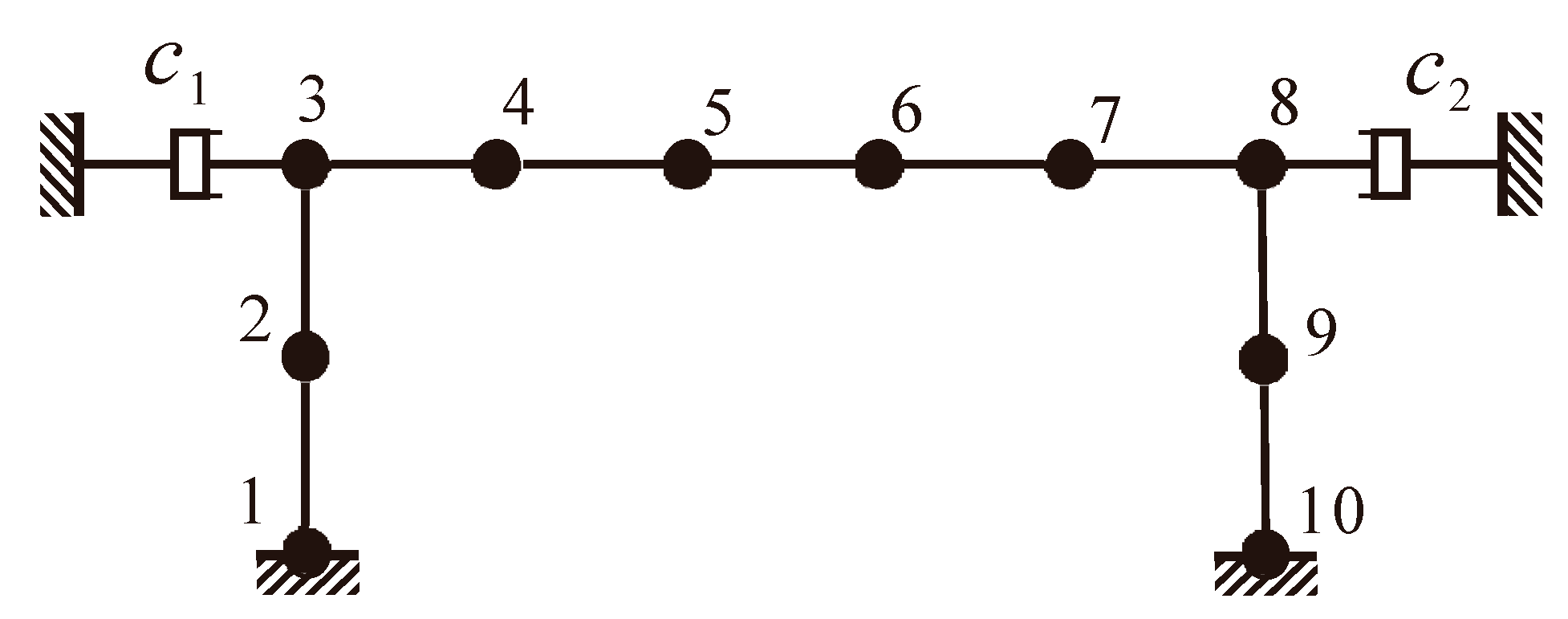
As the additional number of modes, Δn, increases, the result gradually converges to the exact solution. The second example, a simple frame structure [12,35], is used to investigate the effect of Δn on the accuracy of eigenvalues. As schematically shown in Figure 2, the frame structure is idealized as 9 beam elements with 24 DOFs. The Young’s modulus and density of material are 500 N/m2, and 1 kg/m3. The cross-section inertia and area are 1m4 and 1m2. The length of each beam element is 1 m. Using the lumped-mass, the frame has 16 possible real mode shapes. The non-proportional damping arises from a damper attached to node 3 and the other attached to node 8. The damping coefficients of the two dampers are c 1 = 1 0 N . s / m , c 2 = 25 N . s / m . The coupling index α of the frame structure is equal to 1, which indicates that system is highly non-proportionally damped.
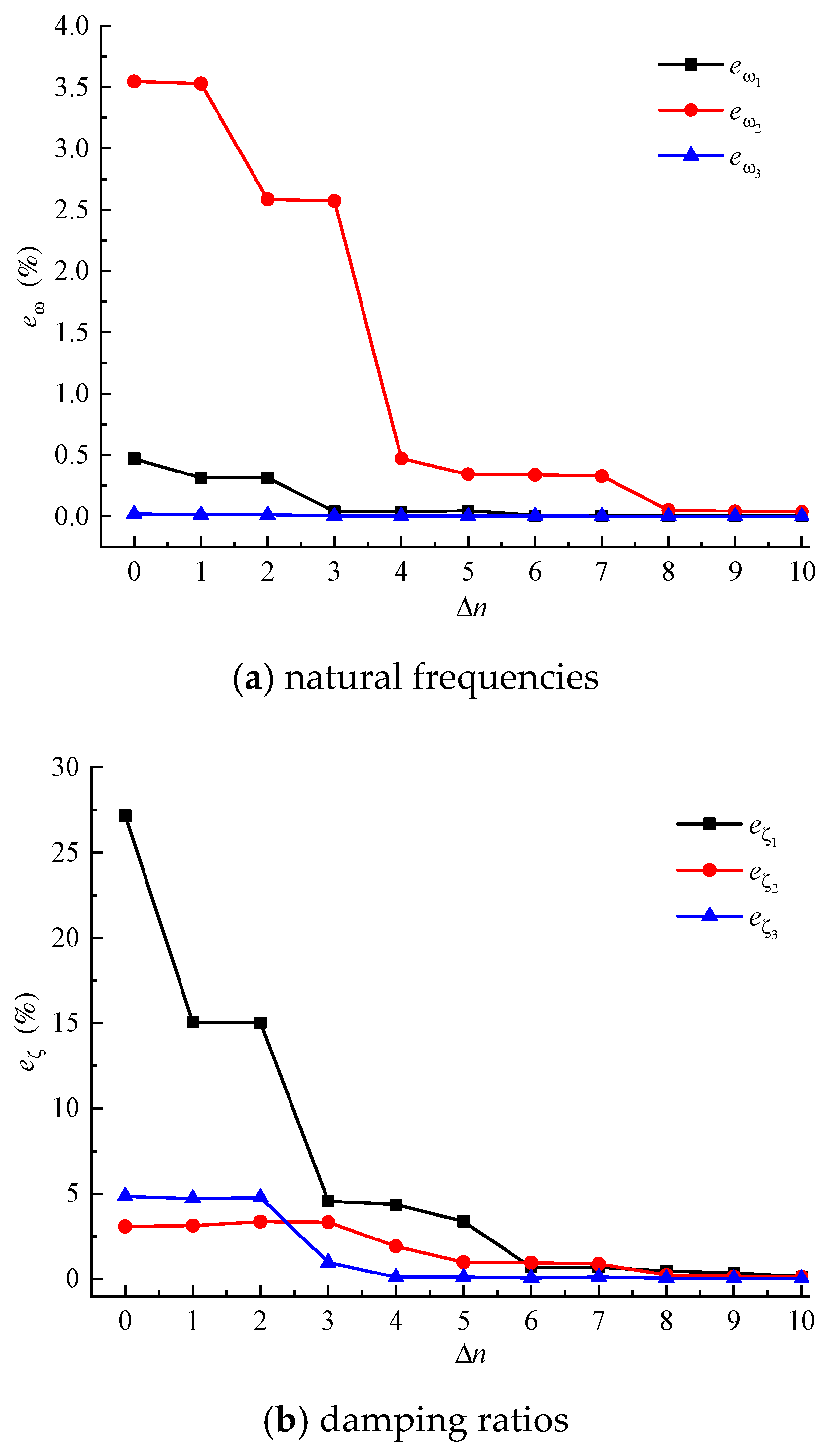
The relative errors of the first three natural frequencies and damping ratios by MPM for various number of modes Δn are presented in Figure 3. It can be seen that the MPM leads to monotonically convergent solutions and gradually converges to the exact solution with the increase of Δn even if it is a highly non-proportionally damped system. It represents that the equivalent proportionally damped system reduces the effect of the deviation damping matrix so that the method can deal with the highly non-proportionally damped system. The curves of error are almost merging into one when Δn is greater than 8.
Then, the first three natural frequencies and damping ratios of the frame system by the proposed perturbation method with n = 11 and n = 16 are shown in Table 4, Table 5 and Table 6. As a comparison, those results obtained by exact method, PDM, FPM [23], and FPM [27] are also listed.
Obviously, the first three natural frequencies and damping ratios of perturbation method are same as the exact solution when n = 16. This is because all of the 16 modes of the frame system are the complete eigenvector set. The relative errors of the first 3 natural frequencies and damping ratios obtained by MPM are within 0.146% when n = 11, which are obviously less than the PDM and FPM. Therefore, the additional number of modes Δn = 8 is enough to obtain sufficiently accurate results. The errors of damping ratios of the other three methods may exceed 25%. Therefore, the proposed method can deal with the highly non-proportionally damped system for the equivalent proportionally damped system reduces the effect of the deviation damping matrix. Appendix A lists the proportionally damping matrix [ c p ] and deviation damping matrix [ Δ c ] after static condensation for the understanding the effect of Equation (8), although [ c p ] and [ Δ c ] need not to be explicitly determined in the proposed method.
The main calculation time for the proposed method contains two parts, one is for solving the characteristic equation of undamped system and the other one is for solving the nonlinear algebraic equations. For the frame with concentrated damper, the first part consumed 0.057 ms, and the second part consumed 0.309 ms, the total time is 0.366 ms. The PDM only needed to solve the characteristic equation of undamped system which consumed 0.057 ms. To solve the characteristic equation of state space, the exact method consumed 0.470 ms. The FPM [23] needs to solve the characteristic equation of undamped system and to calculate the perturbation of undamped system which totally consumed 0.132 ms. The FPM [27] needs to optimize proportional damping coefficient and to solve the characteristic equation of undamped system. It totally consumed 0.123 ms. It can be seen that the time consumed by proposed method is shorter than state space method and longer than the other three existing methods. The advantages of the proposed method will become more prominent as the degrees of the system increase because it only needs to solve the characteristic equation of undamped system. Although the other three methods consumed less time, the accuracy of the proposed method is much higher, especially for high non-proportional damping systems. The proposed method outperforms the others when considering both the efficiency and the accuracy.

4. Conclusions

Non-proportional damping structures widely exist in practical engineering. In this paper, a modal perturbation method is proposed for evaluation of natural frequencies and damping ratios to significantly simplifies the solution process. Based on extensive analyses and numerical results, the following conclusions can be drawn:
(1)
The modal perturbation method transforms the characteristic equation of state space into a set of nonlinear algebraic equations by using the real mode shapes of the corresponding undamped system. The method only requires the first few lower eigenvectors of the undamped system, the calculation time is shorter than the state space method, which will simplify the solution and be convenient to solve the large system.
(2)
With the increase of vibration modes of the corresponding undamped system, the eigenvalues and eigenvectors monotonically converge to exact solutions. Usually j + 8 is enough to obtain sufficiently accurate natural frequencies and damping ratios. When all of the mode shapes of the undamped system are used, the modal perturbation method will obtain the exact solution.
(3)
The equivalent proportionally damped system is close to the non-proportionally damped system to reduce the effect of the deviation damping matrix so that the method can deal with the highly non-proportionally damped system. The method is particularly suitable for finding a few individual orders of frequency and mode for system with highly non-proportional damping.

Author Contributions

Conceptualization, D.P.; methodology, D.P.; investigation, X.F.; writing—original draft preparation, X.F. and J.T.; writing—review and editing, P.L. and Q.C. All authors have read and agreed to the published version of the manuscript.

Funding

This research was funded by the Open Foundation of State Key Laboratory of Disaster Reduction in Civil Engineering (SLDRCE15-01).

Conflicts of Interest

The authors declare no conflict of interest.

Appendix A

The matrices [c], [cp], and [ Δ c ] in the numerical examples are as follows:
Two degrees-of-freedom system, case1:
[ c ] = [ 6.6 0.6 0.6 0.6 ] ,   [ c p ] = [ 4.7395 0.8791 0.8791 1.1581 ] ,   [ Δ c ] = [ 1.8605 0.2791 0.2791 0.5581 ]
Case2:
[ c ] = [ 7.58 0.18 0.18 0.18 ] ,   [ c p ] = [ 4.4172 0.6544 0.6544 1.1288 ] ,   [ Δ c ] = [ 3.1628 0.4744 0.4744 0.9488 ]
Frame with concentrated damper:
[ c ] = [ 0 0 10 0 0 0 0 0 0 0 0 0 25 0 0 0 ]
[ c p ] = [ 2.305 0.063 1.258 0.696 0.087 0.436 0.773 0.431 0.241 0.582 0.116 0.046 0.054 0.255 0.234 0.160 0.063 0.856 0.027 0.167 1.067 0.032 0.625 0.205 0.758 0.187 0.636 0.002 0.262 0.129 0.160 0.741 1.258 0.027 5.264 0.867 0.477 0.273 1.742 0.350 0.805 0.022 0.055 0.819 0.388 0.509 0.054 0.262 0.696 0.167 0.897 0.925 0.652 0.189 0.309 0.175 0.012 0.091 0.496 0.078 0.509 0.658 0.255 0.129 0.087 1.067 0.477 0.652 3.086 0.027 0.434 0.422 1.251 0.390 0.172 0.040 0.055 0.496 0.116 0.636 0.436 0.032 0.273 0.189 0.027 0.743 0.476 0.217 0.501 0.136 0.040 0.221 0.819 0.078 0.046 0.002 0.773 0.625 1.742 0.309 0.434 0.476 3.577 0.007 1.067 0.509 1.251 0.501 0.805 0.012 0.241 0.758 0.431 0.205 0.350 0.175 0.422 0.217 0.007 0.744 0.509 0.103 0.390 0.136 0.022 0.091 0.582 0.187 0.241 0.758 0.805 0.012 1.251 0.501 1.067 0.509 3.577 0.007 0.434 0.476 1.742 0.309 0.773 0.625 0.582 0.187 0.022 0.091 0.390 0.136 0.501 0.103 0.007 0.744 0.422 0.217 0.350 0.175 0.431 0.205 0.116 0.636 0.055 0.496 0.172 0.040 1.251 0.390 0.434 0.422 3.086 0.027 0.477 0.652 0.087 1.067 0.046 0.002 0.819 0.078 0.040 0.221 0.501 0.136 0.476 0.217 0.027 0.743 0.273 0.189 0.436 0.032 0.054 0.262 0.388 0.509 0.055 0.819 0.805 0.022 1.742 0.350 0.477 0.273 5.234 0.897 1.258 0.027 0.255 0.129 0.509 0.658 0.496 0.078 0.012 0.091 0.309 0.175 0.652 0.189 0.897 0.925 0.696 0.167 0.234 0.160 0.054 0.255 0.116 0.046 0.241 0.582 0.773 0.431 0.087 0.436 1.258 0.696 2.305 0.063 0.160 0.741 0.262 0.129 0.636 0.002 0.758 0.187 0.625 0.205 1.067 0.032 0.027 0.167 0.063 0.856 ]
[ Δ c ] = [ 2.305 0.063 1.258 0.696 0.087 0.436 0.773 0.431 0.241 0.582 0.116 0.046 0.054 0.255 0.234 0.160 0.063 0.856 0.027 0.167 1.067 0.032 0.625 0.205 0.758 0.187 0.636 0.002 0.262 0.129 0.160 0.741 1.258 0.027 4.736 0.867 0.477 0.273 1.742 0.350 0.805 0.022 0.055 0.819 0.388 0.509 0.054 0.262 0.696 0.167 0.897 0.925 0.652 0.189 0.309 0.175 0.012 0.091 0.496 0.078 0.509 0.658 0.255 0.129 0.087 1.067 0.477 0.652 3.086 0.027 0.434 0.422 1.251 0.390 0.172 0.040 0.055 0.496 0.116 0.636 0.436 0.032 0.273 0.189 0.027 0.743 0.476 0.217 0.501 0.136 0.040 0.221 0.819 0.078 0.046 0.002 0.773 0.625 1.742 0.309 0.434 0.476 3.577 0.007 1.067 0.509 1.251 0.501 0.805 0.012 0.241 0.758 0.431 0.205 0.350 0.175 0.422 0.217 0.007 0.744 0.509 0.103 0.390 0.136 0.022 0.091 0.582 0.187 0.241 0.758 0.805 0.012 1.251 0.501 1.067 0.509 3.577 0.007 0.434 0.476 1.742 0.309 0.773 0.625 0.582 0.187 0.022 0.091 0.390 0.136 0.501 0.103 0.007 0.744 0.422 0.217 0.350 0.175 0.431 0.205 0.116 0.636 0.055 0.496 0.172 0.040 1.251 0.390 0.434 0.422 3.086 0.027 0.477 0.652 0.087 1.067 0.046 0.002 0.819 0.078 0.040 0.221 0.501 0.136 0.476 0.217 0.027 0.743 0.273 0.189 0.436 0.032 0.054 0.262 0.388 0.509 0.055 0.819 0.805 0.022 1.742 0.350 0.477 0.273 19.736 0.897 1.258 0.027 0.255 0.129 0.509 0.658 0.496 0.078 0.012 0.091 0.309 0.175 0.652 0.189 0.897 0.925 0.696 0.167 0.234 0.160 0.054 0.255 0.116 0.046 0.241 0.582 0.773 0.431 0.087 0.436 1.258 0.696 2.305 0.063 0.160 0.741 0.262 0.129 0.636 0.002 0.758 0.187 0.625 0.205 1.067 0.032 0.027 0.167 0.063 0.856 ]

References

  1. Cruz, C.; Miranda, E. Evaluation of soil-structure interaction effects on the damping ratios of buildings subjected to earthquakes. Soil Dyn. Earthq. Eng. 2017, 100, 183–195. [Google Scholar] [CrossRef]
  2. Králik, J.; Králik, J., Jr. Dynamic analysis of soil-structure interaction effects on NPP building using simplified and solid FE model of layered subsoil. J. Meas. Eng. 2019, 7, 12–19. [Google Scholar] [CrossRef]
  3. O’Riordan, N.J.; Almufti, I.; Lee, J.; Ellison, K.; Motamed, R. Site response analysis for dynamic soil-structure interaction and performance-based design. Proc. Inst. Civ. Eng. Geotech. Eng. 2019, 172, 76–86. [Google Scholar] [CrossRef]
  4. Lu, Z.; He, X.; Zhou, Y. Studies on damping behavior of vertically mixed structures with upper steel and lower concrete substructures. Struct. Des. Tall Spec. Build. 2017, 26, 1–14. [Google Scholar] [CrossRef]
  5. Wei, H.; Jiang, Q.; Zhi, Z. An approach to equivalent damping ratio of vertically mixed structures based on response error minimization. Soil Dyn. Earthq. Eng. 2015, 72, 119–128. [Google Scholar] [CrossRef]
  6. Papageorgiou, A.V.; Gantes, C.J. Equivalent modal damping ratios for concrete/steel mixed structures. Comput. Struct. 2010, 88, 1124–1136. [Google Scholar] [CrossRef]
  7. Losanno, D.; Londono, J.M.; Zinno, S.; Serino, G. Effective damping and frequencies of viscous damper braced structures considering the supports flexibility. Comput. Struct. 2018, 207, 121–131. [Google Scholar] [CrossRef]
  8. Li, Z.; Dong, H.; Wang, X.; He, M. Experimental and numerical investigations into seismic performance of timber-steel hybrid structure with supplemental dampers. Eng. Struct. 2017, 151, 33–43. [Google Scholar] [CrossRef]
  9. Chopra, A.K. Dynamics of Structures: Theory and Applications to Earthquake Engineering; Prentice-Hall: Englewood Cliffs, NJ, USA, 1995. [Google Scholar]
  10. Perotti, F. Analytical and numerical techniques for the dynamic analysis of non-classically damped linear systems. Soil Dyn. Earthq. Eng. 1994, 13, 197–212. [Google Scholar] [CrossRef]
  11. Foss, K.A. Coordinates which uncouple the equation of damped linear dynamic system. J. Appl. Mech. 1958, 25, 361–364. [Google Scholar]
  12. Ibrahimbegovic, A.; Wilson, E. Simple numerical algorithms for the mode superposition analysis of linear structural systems with non-proportional damping. Comput. Struct. 1989, 33, 523–531. [Google Scholar] [CrossRef]
  13. Cronin, D.L. Approximation for determining harmonically excited response of non-classically damped systems. J. Manuf. Sci. Eng. 1976, 98, 43–47. [Google Scholar] [CrossRef]
  14. Igusa, T.; Der Kiureghian, A.; Sackman, J.L. Modal decomposition method for stationary response of non-classically damping systems. J. Earthq. Eng. Struct. Dyn. 1984, 12, 121–136. [Google Scholar] [CrossRef]
  15. Udwadia, F.E. A note on nonproportional damping. J. Eng. Mech. 2009, 135, 1248–1256. [Google Scholar] [CrossRef] [Green Version]
  16. Farghaly, A.A. Parametric study on equivalent damping ratio of different composite structural building systems. Int. J. Steel Struct. 2015, 15, 7–16. [Google Scholar] [CrossRef]
  17. Jae-Seung, H.; Chang-Soon, R. Equivalent damping ratio identification of a non-classically damped structure with vibration control system. J. Wind Eng. Inst. Korea 2017, 21, 121–126. [Google Scholar]
  18. Jiang, Q.; Zhou, Z.; Huang, W. Investigation on the Modal Strain Energy for Dynamic Analysis of Steel-Concrete Vertically Mixed Structures. J. Asian Archit. Build. Eng. 2015, 14, 671–678. [Google Scholar] [CrossRef]
  19. Ashory, M.R.; Ghasemi-Ghalebahman, A.; Kokabi, M.J. An efficient modal strain energy-based damage detection for laminated composite plates. Adv. Compos. Mater. 2017, 147–162. [Google Scholar] [CrossRef]
  20. Charney, F.A.; Mcnamara, R.J. Comparison of methods for computing equivalent viscous damping ratios of structures with added viscous damping. J. Struct. Eng. 2008, 134, 32–44. [Google Scholar] [CrossRef]
  21. Udwadia, F.E.; Esfandiari, R.S. Non-classically damped systems: An iterative approach. J. Appl. Mech. 1990, 57, 423–433. [Google Scholar] [CrossRef] [Green Version]
  22. Adhikari, S. An iterative approach for nonproportionally damped systems. Mech. Res. Commun. 2011, 38, 226–230. [Google Scholar] [CrossRef]
  23. Meirovitch, L.; Ryland, G., II. Response of slightly damped gyroscopic systems. J. Sound Vibr. 1979, 67, 1–19. [Google Scholar] [CrossRef]
  24. Singh, M.P.; Suarez, L.E. A perturbation analysis of the eigenproperties of equipment-structure systems. Nucl. Eng. Des. 1986, 97, 167–185. [Google Scholar] [CrossRef]
  25. Igusa, T.; Der Kiureghian, A. Dynamic characterization of two-degree-of-freedom equipment-structure systems. J. Eng. Mech. 1985, 111, 1–19. [Google Scholar] [CrossRef]
  26. Yang, Y.B.; Huang, W.H. Equipment-structure interaction considering the effect of torsion and base isolation. Earthq. Eng. Struct. Dyn. 1998, 27, 155–171. [Google Scholar] [CrossRef]
  27. Cha, P.D. Approximate eigensolutions for arbitrarily damped nearly proportional systems. J. Sound Vibr. 2005, 288, 813–827. [Google Scholar] [CrossRef]
  28. Lou, M.; Chen, G. Modal perturbation method and its applications in structural systems. J. Eng. Mech. 2003, 129, 935–943. [Google Scholar] [CrossRef]
  29. Lou, M.; Duan, Q.; Chen, G. Modal perturbation method for the dynamic characteristics of timoshenko beams. Shock Vib. 2013, 12, 425–434. [Google Scholar] [CrossRef]
  30. Hračov, S.; Náprstek, J. Approximate complex eigensolution of proportionally damped linear systems supplemented with a passive damper. Procedia Eng. 2017, 199, 1677–1682. [Google Scholar] [CrossRef]
  31. Tang, J.; Wang, W.L. Perturbation method for determining eigensolutions of weakly damped systems. J. Sound Vibr. 1995, 187, 671–681. [Google Scholar] [CrossRef]
  32. Chung, K.R.; Lee, C.W. Dynamic reanalysis of weakly non-proportionally damped systems. J. Sound Vibr. 1986, 111, 37–50. [Google Scholar] [CrossRef]
  33. Kwak, M.K. Perturbation method for the eigenvalue problem of lightly damped systems. J. Sound Vibr. 1993, 160, 351–357. [Google Scholar] [CrossRef]
  34. Claret, A.M.; Venancio-Filho, F. A modal superposition pseudo-force method for dynamic analysis of structural systems with non-proportional damping. Earthq. Eng. Struct. Dyn. 1991, 20, 303–315. [Google Scholar] [CrossRef]
  35. Chen, H.C.; Taylor R, L. Solution of viscously damped linear systems using a set of load-dependent vectors. Earthq. Eng. Struct. Dyn. 1990, 19, 653–665. [Google Scholar] [CrossRef]
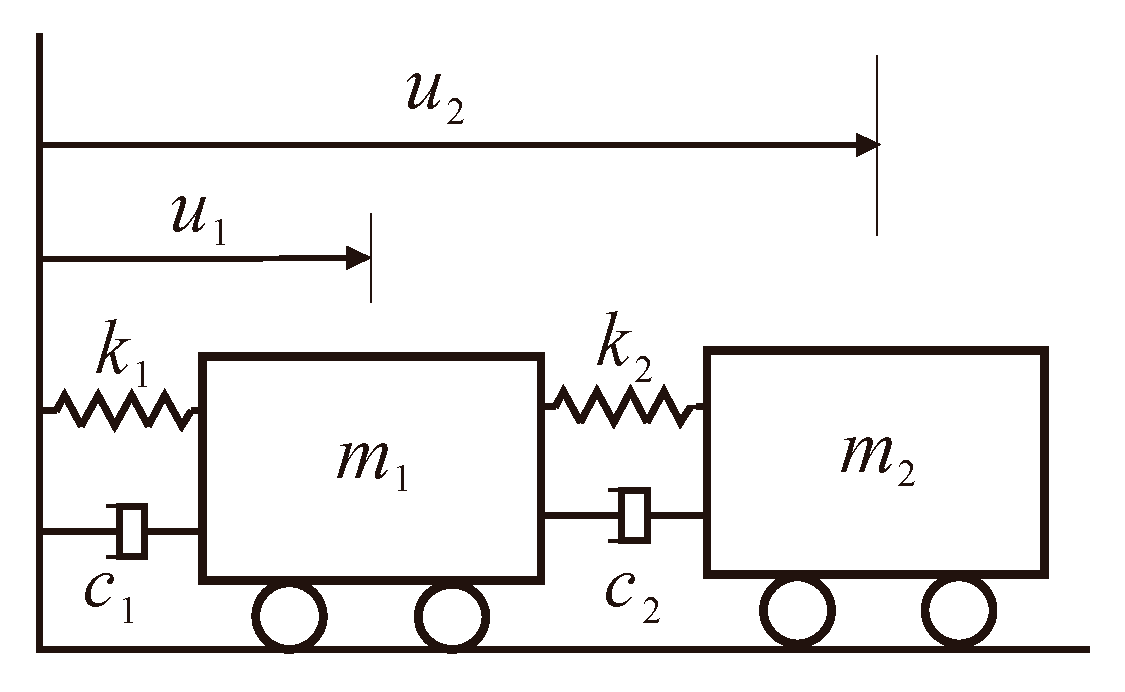
Figure 1. Two degrees-of-freedom system.
Applsci 10 00341 g001
Figure 2. A frame with concentrated damper.
Applsci 10 00341 g002
Figure 3. Relative errors of the first three natural frequencies and damping ratios.
Applsci 10 00341 g003
Table 1. The natural frequencies (rad/s) of the 2 DOFs system.
CaseModeFrequencies (rad/s)
ExactMPMPDMFPM [23]FPM [27]
117.7637737.7637737.6296087.7426087.689488
212.88033612.88033613.10683313.44178413.126397
218.0617408.0617407.6296087.7616537.814849
212.40427012.40427013.10683313.37490513.163732
Table 2. The damping ratios of the 2 DOFs system.
CaseModeDamping Ratios
ExactMPMPDMFPM [23]FPM [27]
110.1717090.1717090.1727450.1702240.171399
20.2303420.2303420.2275170.2218470.227178
210.1872820.1872820.1868510.1836730.182422
20.2080070.2080070.2032830.1992090.202404
Table 3. The coupling index α and relative error e of the 2-DOFs system.
Case α ModeMPMFDMFPM [23]FPM [27]
e ω   ( % ) e ζ   ( % ) e ω   ( % ) e ζ   ( % ) e ω   ( % ) e ζ   ( % ) e ω   ( % ) e ζ   ( % )
10.2371001.7280.6030.2730.8650.9570.181
2001.7581.2264.3593.6881.9101.374
20.7081005.3600.2303.7221.9273.0632.595
2005.6642.2717.8254.2306.1232.694
Table 4. The natural frequencies (rad/s) of the frame system.
ModeFrequencies (rad/s)
ExactMPM (n = 16)MPM (n = 11)PDMFPM [23]FPM [27]
17.6451717.6451717.6450667.609227.6101197.695591
29.0494259.0494259.0455808.742248.8312968.74224
312.72516212.72516212.72513912.7251312.7251312.785979
Table 5. The damping ratios of the frame system.
ModeDamping Ratios
ExactMPM (n = 16)MPM (n = 11)PDMFPM [23]FPM [27]
10.0120890.0120890.0121050.0153730.0153710.0152
20.1402550.1402550.1404600.14310.1416560.14301
30.0005060.0005060.0005070.000550.000550.00055
Table 6. The errors of natural frequencies and damping ratios of the frame system.
Mode e ω   ( % ) e ζ   ( % )
MPM (n = 16)MPM (n = 11)PDMFPM [23]FPM [27]MPM (n = 16)MPM (n = 11)PDMFPM [23]FPM [27]
100.0010.4700.4580.6600.13227.16127.14925.734
200.0423.3952.413.39500.1462.0280.9991.964
300.0000.00000.47800.0018.5998.6968.696