4.1. Optimization Design Scheme
The thickness variation rule of the 791 airfoil was applied to the blade thickening of the multiphase pump; the thickening law is shown in
Table 7. The 791 airfoil is shown in
Figure 8.
The maximum thickness of the airfoil (δ
max) at the hub was determined according to the strength condition [
44], usually estimated roughly according to
where D is the diameter of the impeller shroud of the multiphase pump; its unit is m.
Practice has proven that the thickness of the blade calculated according to the above equation is often too thick, which is not conducive to improving the performance of the pump [
45]. The thickness is related to the chord length, and the relative thickness of the hub section is generally calculated as
and the relative thickness of the shroud section is calculated as
The hub is the thickest part generally, and the thickness varies linearly from the hub to the shroud. The maximum thicknesses of the hub and shroud for the basic model were selected as 9 and 5 mm, respectively. The airfoil from the hub to the shroud of the blade is shown in
Figure 9.
To investigate the effects of the thickness variation in the airfoil from the hub to the shroud of the blade on the hydraulic performance of the multiphase pump, the thickness ratio coefficient
ξ is defined as
where
δh max and
δs max denote the maximum thicknesses in the airfoil at the side of the hub and shroud, respectively, and
ξ indicates the change degree of the blade thickness from hub to shroud.
The thickness ratio coefficients
ξ were all greater than 1 according to the usual regular thick airfoil. To investigate the influence of the multiphase pump when
ξ ≤ 1, different thickening schemes were selected on the basis of ensuring the strength of the blade, as shown in
Figure 10. The thickness ratio coefficient was selected to range from 0.8 to 1.8;
δhmax was set to 7.5, 8, 8.5, and 9 mm, representing schemes 1 to 4, respectively; and
ξ = 1.8 was the thickening scheme of the basic model. As shown in
Figure 10, the maximum thickness of the hub on the same curve was the same; the
x coordinates from left to right represent the increase in the maximum thickness at the side of shroud and the vertical axis represents different thickness ratio coefficients.
The main step of the optimization design of the impeller is: in order to investigate the influence of the thickness variation from hub to shroud on the characteristics of multiphase pump, the thickness ratio coefficient was defined. The variables that affect the thickness ratio coefficient were the maximum thickness of the impeller hub and the maximum thickness of the shroud. Different thickness ratio coefficients were obtained by taking different values for these two key variables, so that the thickness coefficient ratio contained different ranges from 0.8 to 1.8. By comparing the hydraulic performance of the multiphase pump with different schemes, such as the head coefficient and efficiency, analyzing the internal flow condition and the aggregation degree of gas phase in the impeller passage of different schemes, the rule and relation between the mixture transportation characteristics of the multiphase pump and the value of coefficient was finally summarized. By adjusting the value of the thickness ratio coefficient and analyzing the simulation results of different thickness ratio coefficient schemes, the optimization design of the impeller was achieved, the impeller model, which had higher hydraulic performance, could be found. Finally, a multiphase pump with higher mixture transportation performance would be obtained.
4.2. Results Analysis
Figure 11 shows the changes trend of the head coefficient
Ψ and efficiency
η with different thickness schemes under the designed working condition when the inlet gas volume fraction was 0.5.
Figure 11 shows that when
δhmax remained unchanged and
δsmax increased—i.e., reducing the thickness ratio coefficient
ξ—the head coefficient and efficiency increase accordingly in every scheme. The data of the four schemes show the same trend, which is helpful for summarizing the relationship between the hydraulic performance of the multiphase pump and the thickness ratio coefficient. We concluded that the reduction in the thickness ratio coefficient
ξ with the same
δhmax was conducive to improving the boosting capability and efficiency of multiphase pumps. The head coefficient of the modification multiphase pump was 5.8% higher in comparison to the base pump, while the efficiency was 3.1% higher than that of the base pump.
Figure 12 shows the main area of gas accumulation in the flow passage, which is the outlet of the impeller suction side near the hub; the mixing of the gas–liquid two-phase in the other regions of the impeller was better than the accumulation area. Therefore, 10% of the blade height surface was selected to analyze the distribution of the gas–liquid two-phase in the flow passage.
Figure 13 shows the distribution of gas at 10% of the blade height with different thickness schemes when the inlet gas volume fraction was 0.5. Since too many figures will occupy a large space in the article, we selected only the distribution of gas with scheme 1 and scheme 4 in
Figure 13. As the gas phase mainly accumulates at the hub and gradually decreased from the hub to the shroud, the volume distribution of gas phase at 10% of the blade height near the hub was selected for analysis.
Figure 13 shows that, when keeping
δhmax unchanged and increasing
δsmax, which was equivalent to the process of decreasing the thickness ratio coefficient
ξ, the accumulation phenomenon of gas also improved. The gas mainly accumulated at the blade outlet of the suction side near the hub. The gas–liquid two-phase flow near the pressure side was always well mixed, and thus no significant separation phenomenon occurred.
With the linear thickening of the blade from hub to shroud, different values of the thickness ratio coefficient ξ corresponded to different profile lines of the blade; the profile of the pressure side was the same when the thickness ratio coefficient ξ changes. The changes in the airfoil thickness impacted the inclination degree of the blade backside. During the rotation of the impeller, the pressure side and the suction side of the blade acted with force on the two-phase medium. The force will change due to the changes in the inclination degree following the change in thickness. The larger the thickness ratio coefficient ξ, the more inclined the backside of the blade is toward the shroud. Under the coupling action of centrifugal force and the force acted by the suction side of the blade, the high-density liquid phase becomes closer to the area near the shroud and the low-density gas phase moves closer to the hub. When the thickness ratio coefficient ξ ≥ 1, the radial component direction of the force points to the shroud along the hub, which was exerted on the gas–liquid two-phase medium by the suction side of the blade. This is consistent with the direction of the centrifugal force and provides an additional promotion of the separation of the gas–liquid two-phase flow. Thus, the separation of gas–liquid two-phase flow is more serious and causes the hydraulic head of the multiphase pump to decrease. Conversely, when the thickness ratio coefficient ξ < 1, the direction of the force acts on the gas–liquid two-phase as the suction side of the blade points to the hub along the shroud. The direction of the force is opposite to the centrifugal force, which reduces part of the separation inductive force. Therefore, on the premise that the hub thickness meets the strength requirement and the shroud thickness meets the process conditions, reducing the thickness ratio coefficient ξ can improve the two-phase transportation performance of the multiphase pump.
Figure 14 shows the schematic diagram of force on the fluid particle in the axial section of the impeller with the thickness ratio coefficient
ξ > 1 and
ξ< 1. In the figure,
Fc is the centrifugal force,
Fp represents the pressure gradient force, which is caused by the pressure gradient at the side of shroud and hub,
Ft denotes the force applied by the suction side of the impeller—the direction of
Ft is perpendicular to the suction side—and
Ftx is the radial component force of
Ft. The separation inductive force was caused mainly because
Fc >
Fp. The direction of
Ftx changed due to the reduction of thickness ratio coefficient; when the thickness ratio coefficient
ξ < 1, the direction of
Ftx pointed to the hub along the shroud, which reduced the difference between the
Fc and
Fp—i.e., it reduced part of the separation inductive force.
According to the gas distribution at 10% of the blade height, we concluded that the aggregation of gas mainly occurs at the blade outlet of the suction side near the hub. To express the accumulation phenomenon of gas in the flow passage with different thickening schemes more intuitively, the area starting from half the axial length (
e) of the impeller in the axial direction to the outlet in each thickening scheme was selected as the analysis area, where the accumulation phenomenon was the most serious in the impeller and represented the accumulation degree of the gas in the flow passage, as shown in
Figure 15.
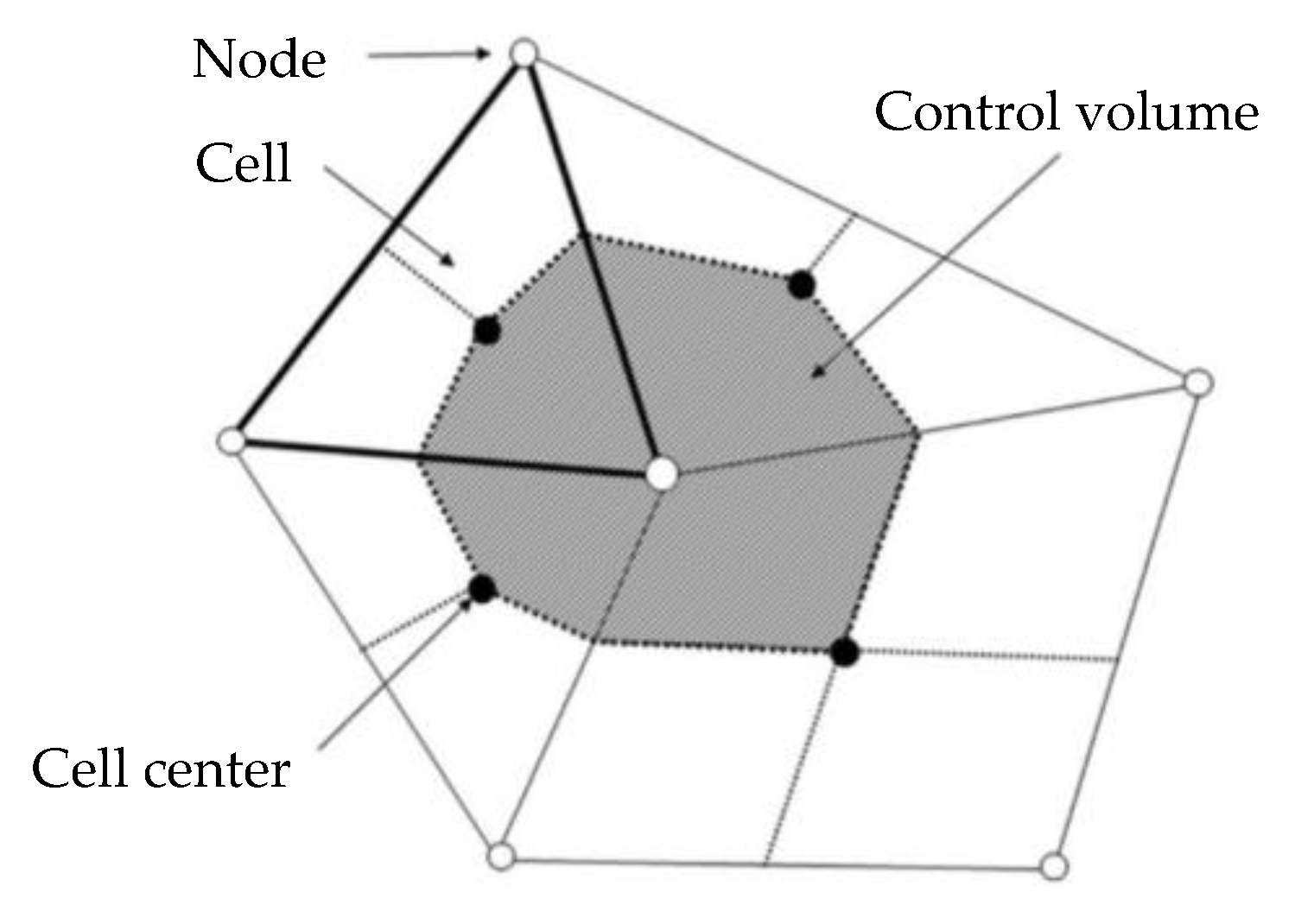
The governing equations were discretized using a finite volume method (FVM), which first involves discretizing the spatial domain using a mesh. The mesh was used to construct finite volumes, which were used to conserve relevant quantities [
46]; the conceptual diagram of the finite volume method is shown in
Figure 16. The scalar variables such as mass, momentum and phase-volume fraction are taken at the cell center [
47]. The gas distribution and grid area date of all grids at 10% of the blade height can be derived from the center of the cell using the internal point method. Firstly, the gas volume fraction and area data whose axial coordinates were greater than half the axial length of the impeller were filtered. Then, the grid area data of the region with a volume fraction greater than 0.7 were filtered and summed.
In order to represent the degree of gas accumulation in the analysis area more intuitively, the aggregation degree λ was introduced in Equation (17). The larger the value, the more serious the gas accumulation is in this area:
where
Sx > 0.5e represents the total grid area of the analysis area, whose axial coordinate is greater than one-half axial length of the impeller;
e is the axial length of impeller and
Svof > 0.7 is the total grid area of the region with a gas volume fraction greater than 0.7 in the analysis region.
Figure 17 shows the variation in the aggregation degree λ with different thickness schemes. When
δhmax is unchanged, the aggregation degree
λ decreases with the decrease in thickness ratio coefficient
ξ, which indicates that the aggregation phenomenon of gas is improved in the flow passage with the reduction in thickness ratio coefficient
ξ. This is contrasting to the change trend of the hydraulic performance of the multiphase pump; i.e., the reduction of the hydraulic performance of the multiphase pump is directly related to the aggregation degree
λ in the flow channel. The value of
λ is inversely related to the hydraulic performance in every thickness scheme. The smaller the value of the aggregation degree
λ, the better the hydraulic performance of the multiphase pump. The gas accumulation in the flow passage of the multiphase pump can be improved by appropriately reducing the thickness ratio coefficient
ξ. The aggregation of the modification multiphase pump is 30.3% lower in comparison to the base pump, which means the aggregation phenomenon of gas phase in the impeller passage is improved after modification.
If complete separation does not occur in 90% of the chord length area from the inlet to the outlet in the flow passage, the airfoil of the impeller can be regarded as a super-separated airfoil. The impeller model with scheme 1 of ξ = 0.8 can delay the completely separated area beyond the region with a chord length greater than 90%. This basically solves the problem of preventing the separation of the gas–liquid phase in the middle and rear parts of the flow passage. The airfoil of the multiphase pump in this scheme can be regarded as a super-separated airfoil.
Figure 18 shows the turbulent kinetic energy of the meridional surface with different thickness schemes. We also selected the turbulent kinetic energy with scheme 1 and scheme 4 in
Figure 18 to save space in the article. The gradient of the turbulent kinetic energy at the inlet of the impeller was relatively large, because the fluid entering the passage of the impeller impacted the surface of the blade, resulting in unstable flow at the inlet. The flow was more stable in the middle area of the runner. The turbulent kinetic energy and gradient near the hub at the outlet of the impeller were higher than in other regions, which was consistent with the gas accumulation areas in the passage of impeller. Combined with
Figure 17, it can be seen that the change trend in the turbulent kinetic energy gradient at the impeller outlet and the aggregation degree
λ of each scheme were consistent with the change in the thickness ratio coefficient
ξ. When the
δhmax was the same, the higher the thickness ratio coefficient
ξ was, the larger the turbulent kinetic energy gradient and aggregation degree. The accumulation of gas caused additional energy loss in the flow passage with the increase of aggregation degree. This reveals why the head coefficient
Ψ and efficiency
η increase with the decreases of thickness ratio coefficient ξ. The gas phase aggregation phenomenon in the flow passage of impeller improved and the energy loss decreased, while the thickness ratio coefficient
ξ decreased, so the hydraulic performance of the multiphase pump improved. Considering the technological factors in the actual processing and the crowding-out effect of the blade, the thickness ratio coefficient in the present study could be set as low as 0.8.


