1. Introduction
With the development of modern science and technology, the forms of load are becoming more diverse, and the application of various unbalanced loads in power electronics technology is also universal. The use of these unbalanced loads of electrical equipment will lead to the unbalance of our power supply system and affect the quality of power supply in the power grid. At the same time, the fluctuation of the load will increase the harmonic distortion of output voltage, and even cause the voltage of the grid to rise or fall, causing oscillations, which will affect the safety of power operation, and various devices have higher and higher requirements for quality of power system input [
1,
2]. The contradiction between these two aspects has become remarkable. Thus, it is necessary to study the control of three-phase inverter under unbalanced grid conditions.
In actual situations, the inverter is often required to have the ability to supply power to unbalanced load. For the three-phase three-wire inverter topology, when the three-phase load imbalance occurs, the phase current also becomes unbalanced, resulting in a deviation of the neutral point potential of the load, output three-phase unbalanced hazardous voltage, thereby affecting the normal operation of the power grid. This is not overcome by the three-leg inverter’s own topology. The three-phase four-leg inverter is widely studied in recent years. It uses three-phase four-wire power supply topology. Compared with ordinary three-phase three-leg inverters, it has one more output bridge leg phase N, which can connect to the load neutral point to control the load neutral point potential, so that the three-phase symmetrical balanced voltage can be output under unbalanced load conditions [
3,
4,
5,
6].
In order to protect the safety of the equipment and human body, the inverter needs to be electrically isolated from the input side and output side. However, the ordinary inverter topology itself does not have the function of isolating electrical. It is necessary to add a frequency transformer between the inverter and load. This will increase the volume and weight of the transformer, the noise pollution of the transformer is serious, the dynamic response performance of the system is poor when load fluctuates [
7,
8].
The high-frequency link (HFL) three-phase four-leg matrix converter (MC) is a new type of inverter topology developed on the basis of ordinary three-phase four-leg inverter. It can satisfy the increasing demand of high power density and does not affect the performance and reliability of the inverter. In the topology, a high-frequency isolation transformer is used to transfer energy, so that it not only has the function of electrical isolation, but also reduces the volume and mass of the system through the frequency rise of the transformer. At the same time, it inherits the advantages of the MC, such as sinusoidal input, bidirectional energy flow, adjustable power factor, and no need for a large capacity energy storage element [
9,
10,
11]. For the HFL three-phase four-leg MC, Yan proposed a closed-loop control strategy based on the symmetrical component method [
12]. The four bridge leg of the MC is controlled as a whole, which leads to large switching losses. When the load fluctuates, the dynamic response performance is insensitive, and the harmonic distortion is large. A mathematically cumbersome coordinate transformation is required, which increases the complexity and difficulty of implementation. An HFL three-phase four-leg MC modulation strategy with a separate control of the front three bridge leg and fourth bridge leg is adopted to improve the utilization efficiency of the switch [
13]. However, in order to obtain good anti-interference and followability, additional adjustment systems are needed to reduce control errors. This not only increases the cost of the system, but also its practicality is limited by the adjustment accuracy. Aijuan adopted a three-dimensional space vector PWM (3D-SVPWM) control strategy to maintain low harmonic distortion of the output voltage under a variable unbalanced load [
14]. However, the concept of three-dimensional space vector is introduced into this method, which is more complex in both control and implementation method. In the development of the power industry, cost control has always been a key factor restricting innovative reform. The above four-wire MC control strategy generally requires a commutation detection circuit, which increases the cost. In addition, in order to obtain high quality output waveform with low harmonic distortion and reduce high switching losses caused by the high switching frequency. Soft switching is an option to reduce switching losses [
15]. However, the soft switching method is limited by the duty cycle and load type. An ideal alternative is hybrid pulse width modulation (HPWM) with no significant switching losses to achieve high quality output waveforms [
16].
This paper proposes a four-wire hybrid pulse width modulation strategy that does not require a commutation detection circuit for the HFL 3 × 4 MC topology. The compensation strategy is adopted to realize the separation of the fourth bridge leg from coupling of the front three bridge leg, so as to achieve independent control of the fourth bridge leg. Under the balanced load condition the compensation for the neutral potential deviation is zero, the modulation wave of the fourth bridge leg does not exist, and only the front three bridge leg operates. When the load is unbalanced, the fourth bridge leg can immediately compensate the neutral point potential deviation caused by the unbalanced load, the front three and the fourth bridge leg jointly control the voltage output. This method enhances the compatibility of 3 × 3 MC and 3 × 4 MC control, makes rational used of power switch and reduces the cost increase caused by switch loss. After applying the compensation method, the fourth bridge leg modulation wave is obtained. At this time, the advantages of the HPWM strategy under the three-wire MC can be completely applied to the four-wire MC. The method is simple in control, the safe commutation problem of the bidirectional switch tube in the four-wire MC topology can be effectively solved without adding any auxiliary commutation detection circuit. It simplifies the complexity of the system and achieves real low cost and high performance.
On the control function, the application of the compensation strategy also speeds up the adjustment of the system under load fluctuations, improve the dynamic response performance, reduce the harmonic distortion rate, and greatly improve the capacity of power grid with unbalanced load. In terms of safety, in addition to the realization of safe commutation, the high-frequency transformer structure in the topology not only has the function of changing the range of the output voltage, but also solves the electrical isolation between the input and output side so that the inverter and personal safety are guaranteed [
17,
18]. In terms of topology, it also has excellent control performance, and has a compact and reliable structure [
19]. Therefore, the proposed strategy makes the HFL three-phase four-leg MC have a good prospect in practicality.
3. Control Strategy of HFL Three-Phase Four-Leg MC
3.1. The Compatibility Control Idea of 3 × 3 MC and 3 × 4 MC
The load in power electronics will be affected by external factors, from balanced to unbalanced load, also from unbalanced to balanced load, and there will be constant switching between balanced and unbalanced state. With the continuous switching of load state, it will inevitably affect the working performance of the inverter, so that the output voltage imbalance and total harmonic distortion rate of the system will continue to increase, finally affecting the power supply quality of the power grid [
21]. If the load is balanced, the three-phase three-wire MC can satisfy the requirements of the power supply. If the load is unbalanced, the three-phase four-wire MC can satisfy the requirements of the power supply.
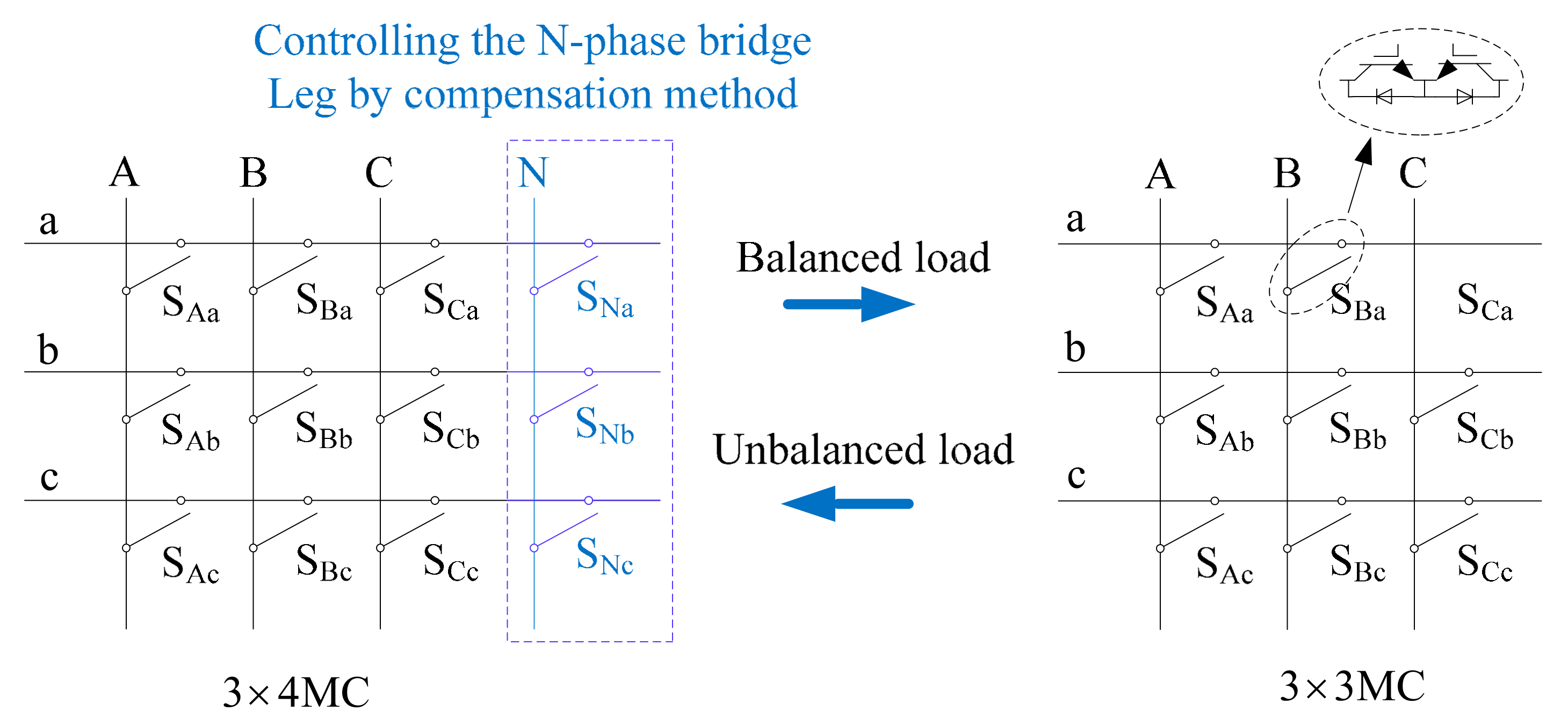
Therefore, we adopt the compatible control idea from HFL 3 × 3 MC to HFL 3 × 4 MC, so that its topology can choose the specific work topology form according to the change of load. When the load is balanced, the fourth bridge leg does not work, only the front three bridge leg work, playing the role of 3 × 3 MC topology. When the load is no longer balanced, the four bridge leg work together to function as a 3 × 4 MC. It can be seen from the above that the fourth bridge leg needs to be controlled by maneuvering, so we must find a strategy to satisfy this idea. As shown in
Figure 2, a compensation method is adopted for the “N-phase bridge leg”, the four bridge leg control function is separated, and the N-phase bridge leg is independently controlled. This method can extend the modulation strategy of 3 × 3 MC to 3 × 4 MC, so that the HFL three-phase four-leg MC can be fully compatible for different load conditions and has good adaptability.
3.2. Decouple Control of HFL Three-Phase Four-Leg MC
According to the characteristics of topology of HFL three-phase four leg MC, we apply a decoupling control strategy to convert the MC into ordinary inverter control problems. This can reduce the difficulty of analyzing the MC and make the modulation process easy to implement [
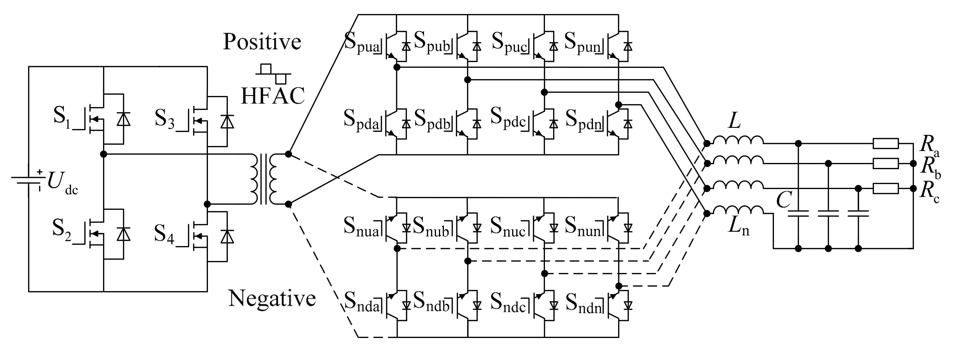
22]. As shown in
Figure 3, when the pre-stage output is a positive square wave, the rear-stage inverter is defined as positive group inverter. On the contrary, the rear-stage inverter is defined as a negative group inverter.
According to the compatible control idea and decoupling modulation strategy, after topology decoupling, the control of the HFL three-phase four-leg MC is firstly designed according to the independent control of the N-phase bridge leg. Then, the front three bridge leg and N-phase bridge leg are controlled by the HPWM modulation strategy based on the compensation method. In other words, it is the process of synthesizing the drive signal of the switch in the topology through the coupling logic.
3.3. The Compensation Strategy of the N-Phase Bridge Leg
According to the decoupling diagram of
Figure 3,
Figure 4 shows the topology of an ordinary three-phase four-leg inverter after decoupled a HFL three-phase four-leg MC.
With respect to the fourth bridge leg of the ordinary three-phase four-leg inverter, the essence of its control is not to obtain the mathematical decoupling through complex coordinate transformation, but to separate the fourth bridge leg from the coupling control of other bridge legs. This paper uses a compensation control scheme. This solution can not only separate the fourth bridge leg control from the coupling with other bridge legs, and the fourth bridge leg structure can also completely compensate for the effects of load imbalance or nonlinearity, which gives full play to the advantages of the four-leg structure to achieve effective control of the inverters.
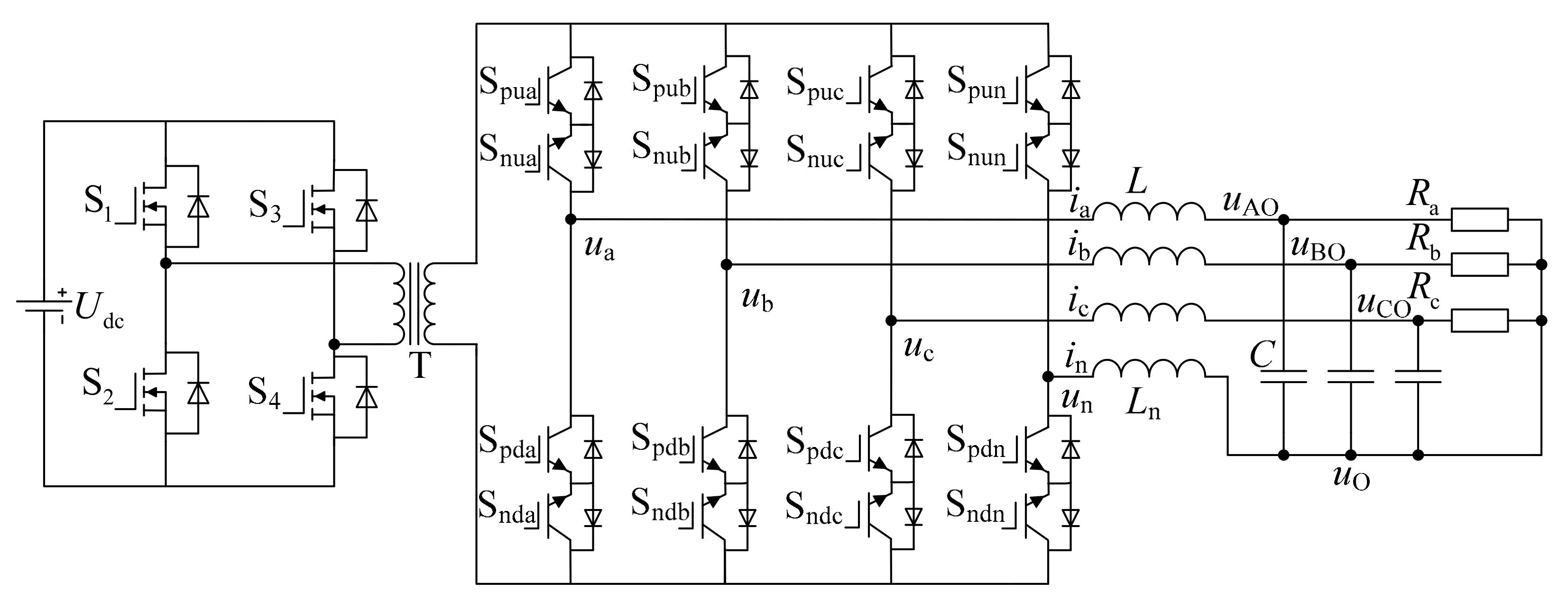
According to the topology of the three-phase four-leg inverter, the terminal voltage of the front three bridge leg is set as follows:
If control ua, ub, uc, and un to make the voltage output from the inverter three-phase symmetrical, and it can satisfy zero sum of front three bridge leg terminal voltage. Then the influence of load unbalance or non-linearity can be completely eliminated by controlling the voltage un of the fourth bridge leg.
According to Kirchhoff’s law of voltage and current, the equation for the three-phase four-leg inverter can be obtained:
In order to realize that the fourth bridge leg voltage can completely compensate the voltage drop caused by inductance. Therefore in the steady state, the voltage of the fourth bridge leg not only compensates the voltage drop of the neutral line inductance, but also compensates the voltage drop of the three-phase inductance, make
L =
Ln. For the given input in Equation (1), when M
1 (
t) = M
2 (
t) = M
3 (
t), we can get
ua +
ub +
uc = 0, At this time, the following can be introduced by the Equation (3):
If the fourth bridge leg control voltage
un is designed as:
The following can be introduced:
According to Equation (6), the output three-phase voltage symmetry can be obtained.
Equation (5) shows the differential calculation of the current
in contained in the modulated wave of the fourth bridge leg, which is not feasible in practical application system, because in the actual working conditions, the differential calculation will amplify the disturbance caused by the switching action, which will easily cause instability of the system and poor quality of the output electrical parameters in the process of regulation. The phase difference between d
in/d
t and ∫
ind
t is approximately 180°, and the amplitude ratio relationship is approximately
ω2, so the integral can be equivalent to a negative differential in phase so that the integral term can be used instead of the differential term in the adjustment parameter. Therefore, the fourth bridge leg control design can use (4/3)
ω2L∫
ind
t instead of −(4/3)
Ld
in/d
t, then in the actual system, the fourth bridge leg controller is:
The
k (
uAO + uBO + uCO) term is added to the actual control
un to adjust the three-phase output voltage rapidly. Therefore, the modulation wave of the fourth bridge leg is:
Due to the excellent control performance of HFL three-phase four-leg MC topology and the rapid regulation of compensation method, this makes the system have less voltage fluctuations and the dynamic response performance well during sudden load change.
3.4. Hybrid Pulse Width Modulation Control Strategy of HFL Three-Phase Four-Leg MC
After decoupling, the positive and negative inverters work in coordination according to the HPWM modulation strategy: When the positive inverter works, the eight unidirectional switches of the negative group inverter are all turned on, acting as a freewheeling circuit. On the contrary, the negative group works also has this relationship. Taking the A-phase bridge leg as an example, the control principle of the four-wire MC switch drive signal is given, the logic implementation circuit is designed.
Firstly, the sawtooth wave
uca and the sinusoidal modulation wave
usa are compared to obtain two complementary sinusoidal pulse width modulation (SPWM) pulses. Then two high-frequency square waves
u1,
u2 with a duty cycle of 0.5 and complementary are used to logically combine with the SPWM pulse. Finally, four switch drive signals on the phase A bridge leg are obtained. The waveform diagram is shown in
Figure 5. In the figure, the amplitude of sinusoidal modulation wave
usa is 1, the amplitude of sawtooth wave
uca is 0.8.
u1 and
u2 represent the positive and negative high-frequency square waves, respectively.
uSkia represents the four driving signals of the phase A bridge leg.
Figure 5 shows the control principle waveform of HPWM control based on de-re-couple, and it is easy to understand the control strategy from the figure. Among them, the high-frequency transformer passes a bipolar high-frequency square wave signal, and it can be known that the transformer operating frequency and the switching frequency of high-frequency inverter bridge are still the same, so it can greatly reduce the size of the transformer and output filter links.
u1,
uSPWM is defined as “1” with high level and “0” with low level using the following switching function:
The control logic truth (shown in
Table 1) is listed by the above control principle. The definitions of the symbols in
Table 1 are shown in
Table A1.
From
Table 1, we can obtain the logic equation of four driving signals of the phase A bridge leg:
In addition, the three-phase high-frequency link matrix converter (HFLMC) is modulated in the control circuit by using an integrated HPWM modulation strategy in which the drive signal of the pre-stage high frequency inverter and the drive signal of the rear-stage MC are combined. Moreover, the HPWM control, itself, has an adaptive one-step commutation, which reduces the commutation difficulty and switching stress, ensuring safe operation of the system [
23].
Similarly, the driving signals of the B, C, and N-phase switches can also be obtained, thereby implementing the control of the four bridge leg of rear-stage MC.
4. Simulation Study
In order to further verify the feasibility and correctness of the theoretical analysis, in this section, the simulation model of the high-frequency link three-phase four-leg matrix converter is built by using the software of MATLAB/Simulink. The proposed modulation strategy is simulated and verified by changing the load condition of the matrix converter. The simulation parameters are shown in
Table 2. Definitions of abbreviations in
Table 2 are shown in
Table A2.
According to
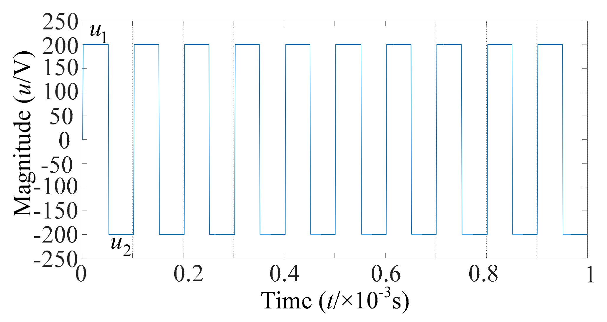
Table 2, when the input DC voltage is 200 V, the high frequency transformer coil turns ratio is 1: 1. The simulation can obtain the high-frequency AC square wave output by the pre-stage inverter, as shown in
Figure 6. The waveforms
u1 and
u2 in the figure are high-frequency square waves with a duty cycle of 0.5 and complementary, which is consistent with the strategy used in this paper.
4.1. Balanced Load
When we use a high-frequency link three-phase four-leg matrix converter system to control the three-phase balanced load, the load conditions are A, B, and C-phase resistance equals to 15 Ω. The output three-phase voltage and current waveforms of the inverter are shown in
Figure 7a,b.
Figure 7c shows the current waveform of the neutral line. The high current ripple flowing through
Udc is shown in
Figure 7d.
The simulation results show that HFL three-phase four-leg MC can play the role of the 3 × 3 inverter, verifying the superiority of the proposed compatible control strategy. The compatibility of the three-phase four-leg inverter to the three-phase three-leg inverter control is improved from the control method, and the versatility of the inverter to balanced and unbalanced conditions is enhanced from the load capacity.
4.2. Unbalanced Load
Keep the B-phase and C-phase resistances unchanged at 15 Ω, replace the phase A resistor with 50 Ω, changing the system with a balanced load to an unbalanced load.
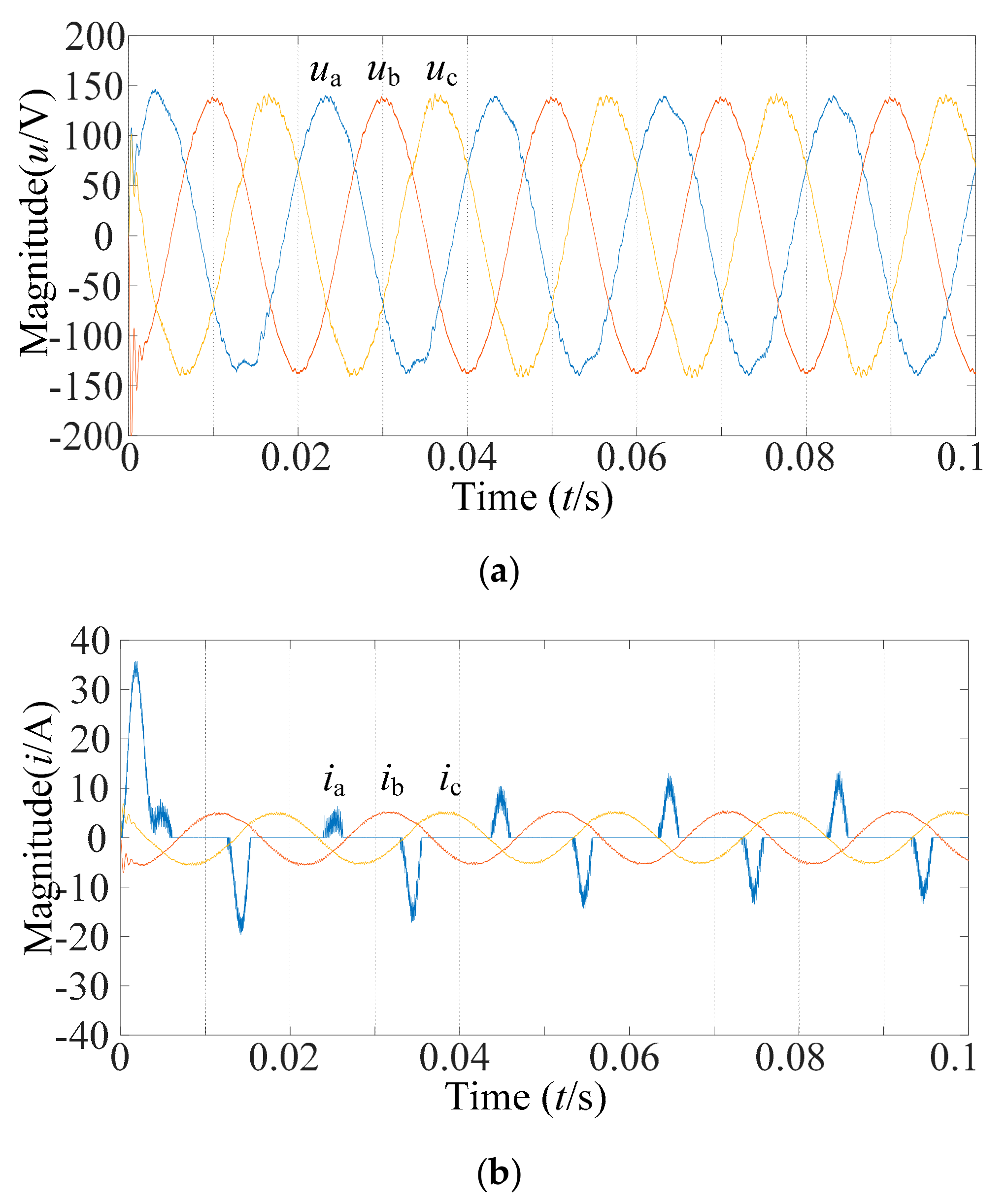
Figure 8a,b shows the three-phase voltage and current waveform of the high-frequency link three-phase four-leg matrix converter under unbalanced load, respectively. The neutral line current waveform is given in
Figure 8c. In order to verify that the proposed modulation strategy can make HFL three-phase four-leg MC transmit sinusoidal voltage to the power grid, the harmonic analysis of the output voltage of the A-phase unbalanced load is shown in
Figure 8d. The η THD of A-phase voltage is 0.81%, with almost no low-order harmonic, only the fundamental wave, and its amplitude is 136.8. It can be seen from the waveforms in the figure that the inverter shows good steady-state performance under the unbalanced load.
Figure 8e shows the high current ripple flowing through
Udc under unbalanced load.
4.3. Mutation Load
In order to investigate the dynamic response speed of the system, the mutation load was simulated.
Figure 9 shows the simulation results of the load from the balanced state to unbalanced state. The load conditions are as follows: A-phase resistance is added to 50 Ω from 15 Ω at 0.055 s, Both B-phase and C-phase resistances are 15 Ω.
Figure 9a,b show the three-phase output voltage and current waveform, and
Figure 9c shows the neutral line current waveform. It can be seen from the figure that the output voltage waveform only shows a slight glitch when the load is abrupt, the time is very short, indicating that the inverter system has a faster response speed.
Figure 9d,e shows the A-phase voltage harmonic analysis under load sudden change. There is still almost no low-order harmonic, the amplitude of the fundamental wave at the sudden change point becomes 136.5, and total harmonic distortion is slightly improved. After the mutation point, the total harmonic distortion recovers to 0.80%. The waveform of current flowing through
Udc in the case of a sudden load change is shown in
Figure 9f.
4.4. Nonlinear Load
A benchmark nonlinear load is formulated in IEC standard, and this nonlinear load circuit is shown in
Figure 10. We use this benchmark nonlinear load to test the capability of matrix converter with nonlinear load.
Figure 11 shows the simulation results under nonlinear load conditions. The load conditions are: Phase A uses this benchmark nonlinear load, capacitance is 1000 μF, resistance is 50 Ω, both B-phase and C-phase resistance are 15 Ω.
Figure 11a shows the three-phase output voltage waveform, and
Figure 11b,c show the current and neutral current waveform. The cusp current waveform in the three-phase output current waveform diagram is the A-phase output current. It can be seen from the figure that the A-phase output current waveform tends to be stable in a short time after the simulation starts, the waveform is no longer changed. It can be seen from
Figure 11d that the phase A output voltage has only a small number of low-order harmonics, the total harmonic distortion rate is 2.59%, fundamental amplitude is 136.4. It can be seen from these waveforms that the distortion and imbalance of the output voltage are very small even when a high-power non-linear load is attached. The waveform of current flowing through
Udc under nonlinear load is shown in
Figure 11e.
It can be seen from the simulation results of the converter with the above three unbalanced loads that the proposed control strategy enhances the ability of HFL three-phase four-leg MC to adjust the output balance voltage. A stable three-phase symmetrical sine wave can still be output when the load fluctuates. It can effectively reduce the harmonic distortion rate, and the system has a strong load carrying capacity.
5. Conclusions
From the above analysis and simulation results, it can be proved that the combination of HPWM modulation and compensation modulation proposed in the HFLMC topology has the ability to withstand unbalanced loads perfectly. In the control strategy, the safe commutation of the bidirectional switch can be realized without other auxiliary detection circuits, which simplifies the system complexity, reducing the control cost. At the same time, the control idea of integrated current is adopted to change the problem that the previous HFL 3 × 4 MC control strategy cannot eliminate the interference when the load fluctuates, which shortens the adjustment response time of the system during load switching, reduces the THD. In safe operation, the commutation process is a one-step adaptive commutation that is naturally accompanied by HPWM control, the electrical isolation of the high frequency transformer structure ensures the safety of the inverter and human body. In terms of overall machine efficiency, the fourth bridge leg compatible control idea improves energy utilization while reducing system losses. In addition, the topology is compact and reliable, reducing the size and weight of the system. The method is simple and efficient, reducing the complicated calculations in previous control strategies. Therefore, the proposed control strategy, with many advantages, is expected to provide a useful reference for the practical application of the HFL three-phase four-leg MC.


