Abstract
This paper presents an adaptive time-delayed control based on the sliding-mode (ATDC-SM). The proposed ATDC-SM provides a new adaptive law imposing time-varying boundedness that is developed to adjust the control gains appropriately while suppressing the negative impact generated by the robot manipulators. Moreover, the control gains are constructed as a continuous function with a fast adaptation rate and hence can remedy chattering and fluctuation inherent in the existing adaptive time-delayed control. These synergistic effects provide a fast convergence rate while producing stable control gains. Besides, the proposed ATDC-SM uses one-sample delayed estimation to cancel out complex nonlinear dynamics and unknown disturbances. Thus, it produces a simple structure but effective approach due to this estimation. From these benefits, the proposed ATDC-SM provides precise tracking performance without undesired side effects. It is shown that the tracking errors are uniformly ultimately bounded through a Lyapunov function. The effectiveness of the proposed ATDC-SM is illustrated through simulation with a one-link robot manipulator, which is compared to that of the existing control approaches.
1. Introduction
In a number of industrial fields, robot manipulators have been used to perform complex and repetitive tasks such as assembling [1], drilling [2], and assisting [3] works. Such robot manipulators are constantly updated to perform more sophisticated tasks for various applications in biotechnology [4] and nanotechnology [5]. These industries require precise tracking performance with robustness. However, as the dynamics of robot manipulators typically contains high non-linearity, coupling dynamics, uncertainties, and unknown disturbances, it is challenging to obtain exceptional tracking performance while operating robot manipulators.
To implement the precise tracking of robot manipulators, various control approaches have been developed over the past few decades [1,6,7,8,9,10]. In [1,6], computed torque approaches have been designed for compensating uncertain and unknown dynamics while using a system model. In [7,8], sliding-mode control approaches have been presented for enhancing robustness while suppressing unknown disturbances. In [9,10], adaptive control approaches have been developed for adjusting appropriate gains, which are robust control approaches. However, since these control approaches are complicated and depended on the information of a system model, they cannot be used to easily implement the robot manipulators.
To address the problem, the time-delayed control (TDC) scheme has received considerable attention owing to its properties. As a key property of the TDC, TDC uses time-delayed estimation (TDE) which is a one-sample delayed information to cancel uncertainties and unknown disturbances on robot manipulators. Furthermore, since the structure of the TDC is simple, it is an inexpensive solution. For this reason, TDC has been known to be a practical and effective control approach, which has been successfully applied in various applications, including robot manipulators [11], unmanned aerial vehicles [12], DC–DC converters [13], and missile guidance systems [14]. However, studies regarding TDC have not fully matured yet primarily owing to the difference between TDE and real information (called TDE error) which is significantly affected by abrupt disturbances such as Coulomb friction.
Some researchers have attempted to solve these problems by combining TDC with auxiliary control approaches, including gradient estimators [15], terminal sliding-mode controls [16], fuzzy controls [17], and adaptive sliding-mode controls [18]. As the above-mentioned approaches effectively suppress TDE errors by using the auxiliary controls, they provide better tracking performance than TDC without auxiliary controls. However, when abrupt disturbances (e.g., Coulomb friction) occur, the excessive gains of auxiliary controls may be required, thereby resulting in chattering or fluctuation. Furthermore, the TDC scheme employs fixed control gains whose tuning may be time-consuming, and then the tracking performance of TDC with inappropriate control gains can still be improved. Another commonly implemented solution is the pairing of two TDCs with adaptive control gains [19,20]. These control approaches have been developed to provide more fundamental remedies, which have time-varying control gains instead of fixed control gains in the TDC, thereby yielding appropriate control gains in the TDC results. In [19], this approach employed a modified Nussbaum function-based scheme that is applied to the time-varying control gains of the TDC for estimating control gains appropriately. However, since the adaptive law used to adjust the control gains is based on angular acceleration using numerical differentiation, undesired side effects such as noise may be generated, and hence it may not be easy to obtain precise tracking performance in real robot manipulators. In [20], the adaptive law of control gains is based on sliding variables with damping terms derived from sliding-mode control. Owing to the control gains in the damping term, this technique provided more stable results than time-varying control gains in [19]. The adaptive law, however, may require a long time to converge to an equilibrium point because of the damping terms. Furthermore, these two approaches do not theoretically complete the proof of the system stability because they have not demonstrated their inherent stability criteria.
To solve these problems, a new adaptive time-delayed control (ATDC) [21] scheme was developed, which was applied to robot manipulators. First, this approach theoretically proved the stability criteria for the TDC with adaptive control gains. This adaptive law is based on the sliding variable without damping terms, which is proportional to the magnitude of sliding variable. Additionally, the adaptive control gains of ATDC can be appropriately adjusted to obtain precise tracking performance because the control gains can increase significantly from small positive values. From these benefits, ATDC provides precise tracking performance with robustness. Although this approach is effective, its control gains create serious and inherent problems because they comprise a discontinuous function. In other words, as the control gains cause the chattering or fluctuation, the tracking performance and robustness may be degraded in robot manipulators. Furthermore, the adaptive law for the control gain has a time-invariant boundedness, which provides a point where the control gain increases or decreases. Setting the time-invariant boundedness is a time-consuming task and hence is difficult to achieve precise tracking performance without undesired side effects. In this regard, a new ATDC with effective and practical adaptive law should be developed.
In this paper, we propose an ATDC based on the sliding-mode (ATDC-SM). The proposed ATDC-SM provides a new adaptive law with imposing time-varying boundedness for adjusting the control gains appropriately. This approach guarantees that the sliding variables enter a vicinity of the sliding manifold within a finite time. The vicinity of the sliding manifold is small, which is called time-varying boundedness (TVB) in this paper. It can be adjusted to achieve an appropriately adapted speed with the control gains, which is inversely proportional to the magnitude of the sliding variables. For example, when the magnitude of the sliding variables is large, there is room to increase the control gains because the TVB decreases. This is a result of fast response. Meanwhile, when the sliding variables stay near the sliding manifold, an increase of control gains may cause undesired side effects such as chattering or fluctuation. To remedy this problem, TVB will be arbitrarily increased, which creates a region where the control gains decrease to avoid undesired side effects. Therefore, TVB can be adjusted appropriately to ensure fast response without undesired side effects from a new adaptive law. Moreover, the control gains of the proposed ATDC-SM comprise a continuous function, producing stable control gains. Although the continuous function may exhibit a slow adaptation speed of control gain compared with the discontinuous function, the proposed one provides a room for improving the adaptation speed owing to the TVB. Also, the proposed ATDC-SM uses the TDE technique to cancel out complex nonlinear dynamics and unknown disturbances and provides a simply structured but effective method. It is shown that the tracking errors are uniformly ultimate boundedness (UUB) by using a Lyapunov approach [22]. The effectiveness of the proposed ATDC-SM is illustrated through a simulation with a one-link robot manipulator, which is compared with that of the conventional ATDC [21].
The reminder of this paper is organized as follows: In Section 2, the conventional ATDC scheme is briefly introduced and a presentation of the proposed ATDC-SM scheme for a robot manipulator is presented. In Section 3, the effectiveness of the proposed ATDC-SM scheme is explained through the simulations. In Section 4, the feasibility of the proposed ATDC-SM scheme is verified based on additional simulations. In Section 5, a summary of this paper is presented.
2. Adaptive Time-Delayed Control Schemes
2.1. Conventional Adaptive Time-Delayed Control Scheme
The mathematical model of single-input single-output (SISO) robot manipulator can be described as
where , , are the joint angle, joint angular velocity, joint angular acceleration, respectively. is the moment of inertia, is the Coriolis force, is the gravity force, and is the friction force. Finally, and are the control torque input and the disturbance torque, respectively.
A constant is introduced in Equation (1), resulting in the following equation:
where will be introduced shortly in this section. In this paper, we applied the following well-known assumptions [23]:
- for certain positive values and
- for a small sampling time L and the upper-bounded value .
Representing Equation (2) in a compact and simple form yields
where . As it is difficult to obtain in industrial fields, we use its estimate [24,25] as follows:
which is one-sampled delayed estimation based on the sampling time L. It is called time-delayed estimation (TDE). is the one-sample delayed joint angular acceleration of .
As a simple estimate of in Equation (4), the conventional adaptive time-delayed control (ATDC) scheme [21] can be constructed as
where is the control input of the conventional ATDC and is the sliding variable to be determined in the next section. The adaptive control gain is defined as
where and is a positive value. Subsequently, the adaptive law is
where and are positive design values. is a positive update parameter, which is upper-bounded by . The stability of the conventional ATDC of Equation (5) is guaranteed under the following Lemma 1.
Lemma 1.
[21] If the control gain in Equation (6) is chosen to satisfy the following criteria:
for all time , then the as and the TDE errors are bounded by constant , .
It implies that the control gain should be chosen to guarantee the boundedness of the TDE error .
The control gain in Equation (6) is constructed as a discontinuous function owing to , and hence the conventional ATDC of Equation (5) provides an easy response to unknown disturbances or undesired side effects. However, since this approach is based on , it may cause chattering or fluctuation. Moreover, may temporarily fall away from 1, and thus the stability criteria in Lemma 1 may not be satisfied. From this point of view, it can also be said that the control gain with adaptive law can be further improved. The control gain with a new adaptive law is proposed in the next section.
2.2. The Proposed Adaptive Time-Delayed Control Scheme
In this section, we propose an ATDC with a new adaptive law that is based on the sliding-mode [26]. The sliding variable used in the sliding-mode yields
where is the sliding gain. As is a positive design parameter, serves to improve the speed of reaching equilibrium point when increases.
By using the sliding variable , we construct the proposed ATDC based on the sliding-mode (ATDC-SM) as below:
where is a control input of the proposed ATDC-SM. The time-varying control gain of the proposed ATDC-SM is defined as
where is a positive value for adjusting the adaptation speed of the control gain. The derivative of the update parameter is defined as
where is a positive design value for adjusting the speed of the update parameter and . The TVB is defined as where , , and are tunable positive gains for adjusting . From these values, it is noted that the update parameter is tuned for achieving a suitable control gain .
As shown in Equation (11), the proposed adaptive law is based on the , which can adjust the increasing or decreasing points of the update parameter . These points vary in position around the sliding manifold. In other words, can be used to adjust the magnitude of the update parameter that increases or decreases appropriately. For , the update parameter has two adaptation rules according to the : and .
- When , the update parameter increases until . Subsequently, is a time-varying parameter, which is inversely proportional to . This implies that becomes smaller when the sliding variable moves away from the sliding manifold. They exhibit an inverse relationship: when the time-varying parameter is small, the update parameter provides a fast response and will be large consequently. On the other hand, when the sliding variable is in the vicinity of the sliding manifold, a large update parameter may cause undesired side effects, e.g., chattering or fluctuation, owing to excessive control torque. To avoid this problem, in Equation (11) is increased to a point where it will quickly create a region in which the update parameter decreases.
- When , the update parameter is decreased to overcome the undesired side effects. However, it is difficult to avoid chattering or fluctuation if the adaptation speed of the update parameter is slow. In order to solve this problem, this paper proposes which is inversely proportional to the magnitude of the sliding variable . It implies that the control gain provides fast adaptation speed and hence can reduce chattering and fluctuation.
Owing to the proper control gain with fast adaptation speed of the update parameter , the proposed ATDC-SM provides good tracking performance without the undesired side effects, e.g., chattering or fluctuation. It is shown in Appendix A that the proposed ATDC-SM has uniformly ultimated boundedness (UUB).
Theorem 1.
For a robot manipulator (Equation (1)) with the proposed ATDC-SM in Equation (9), the sliding variables stay within the close vicinity of the sliding manifold within a finite time , which is guaranteed to be uniformly ultimately bounded for as shown below:
where is any positive value that is introduced in the Appendix A.
3. Simulation
3.1. Simulation Setup
To illustrate the merits of the proposed ATDC-SM, the simulation is constructed as a one-link robot manipulator. The mathematical model (shown in Figure 1) is defined as
where m is an unknown mass of the robot manipulator, l is the length of the link, k is a spring coefficient, g is gravity acceleration, is the coefficient of viscous friction, is the coefficient of Coulomb friction, n is the scale factor, and is random noise. Then, the following values were set: 5 (kg), 9.81 (m/s), 1 (m), 5, 10, 100, and 10. The control parameters of the proposed ATDC-SM in Equation (9) were chosen to be , , , , , , , , , and .
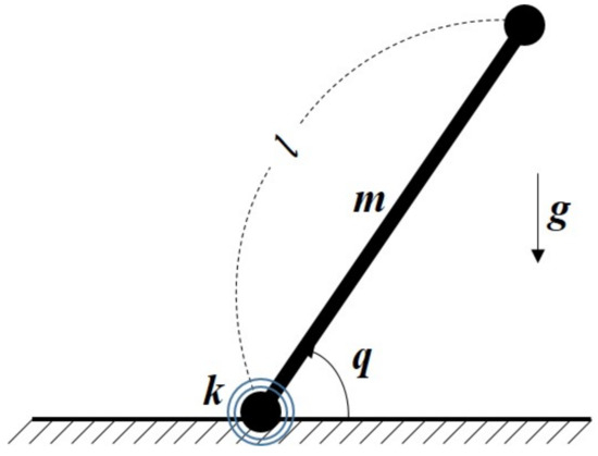
Figure 1.
A one-link robot manipulator.
3.2. Simulation Description
The objective of this simulation is to make the desired joint angle precisely follow the real joint angle . The desired joint angle is shown in Figure 2. The length of link as “1” is defined to make readers understand moment of inertia (MOI), i.e., , of a one-link robot manipulator. For the fair comparisons, the effectiveness of the proposed ATDC-SM is compared with that of the latest control approaches based on sliding-mode, including model-free nonsingular terminal sliding-mode control (MNTSMC) [16], adaptive sliding-mode control (ASMC) [18], and the conventional ATDC [21].
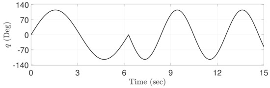
Figure 2.
Trajectory of the reference angle.
3.3. Simulation Results
Figure 3 shows TVB generated by the proposed ATDC-SM that allows the adaptive law used in Equation (11) to provide remarkable results. The change in adaptive law directly affects the control gain. In other words, the TVB is decreased to obtain fast convergence rate, and thus control gain is increased rapidly. Contrastingly, the TVB is increased to avoid undesired side effects such as fluctuations or chattering caused by too large control gain, and it is a result that the control gain is rapidly decreased. The detailed results of the control gain are shown in Figure 4.
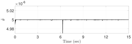
Figure 3.
Time-varying boundedness computed by the proposed ATDC-SM.
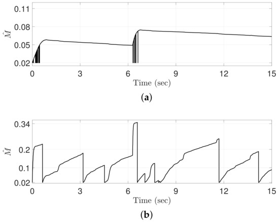
Figure 4.
Control gains computed by (a) the conventional ATDC and (b) the proposed adaptive time-delayed control based on the sliding-mode (ATDC-SM).
Figure 4 shows the control gains generated by the conventional ATDC and the proposed ATDC-SM. The discontinuous control gain of the conventional ATDC moves instantaneously to its minimum value, causing chattering and fluctuations as shown in Figure 5. These effects may result in a severe degradation in the tracking performance of robot manipulators. The proposed ATDC-SM with TVB, however, provides a fast adaptation speed, and its control gain is decreased to avoid the undesired side effects while maintaining a continuous control gain. As shown in the next figures, the proposed ATDC-SM is effective in reducing undesired side effects while achieving better tracking performance.
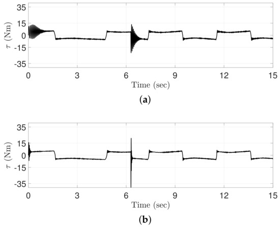
Figure 5.
Control inputs computed by (a) the conventional ATDC and (b) the proposed ATDC-SM.
Figure 5 shows the control torques generated by the conventional ATDC and the proposed ATDC-SM. As shown in Figure 4, the control gain is directly related to the control torque. In fact, the conventional ATDC causes undesired side effects, such as chattering, because it employs the control gain with a discontinuous function. By contrast, the control gain of the proposed ATDC-SM is based on continuous functions, which does not cause undesired side effects such as chattering. However, the chattering generated in the transient region, as shown in Figure 5, is caused by the sensor noise term used in Equation (12) of the revised paper. In other words, the proposed ATDC-SM results in reducing undesired side effects such as chattering and producing a stable control torque compared with the conventional ATDC.
Figure 6 shows the sliding variable generated by the proposed ATDC-SM. The sliding variable represents irregular values that provide instantaneous large values. These points appear at approximately 2 s, 5 s, 7 s, 8 s, 10 s, 11 s, and 14 s, as shown in Figure 2. Therefore, the undesired side effects are caused by the non-differentiable point and the friction forces [27] when the direction of operation of the motor installed in the robot manipulator changes. However, as shown in Figure 6, the proposed ATDC-SM helps the sliding variables converge to the sliding manifold, and subsequently they stay in the vicinity of the sliding manifold.
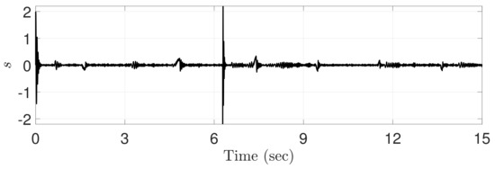
Figure 6.
Sliding variable computed by the proposed ATDC-SM.
Figure 7 shows the tracking errors of four control approaches, i.e., MNTSMC [16], ASMC [18], the conventional ATDC [21], and the proposed ATDC-SM. The effect of change on control gain generated by the adaptive law with a time-varying boundedness in the proposed ATDC-SM is significant, and it can be observed that the fast convergence speed is achieved at approximately 2 s, 5 s, 7 s, 8 s, 10 s, 11 s, and 14 s. In addition, the proposed ATDC-SM provides more stable results without undesired side effects such as chattering compared with the existing control approaches, including MNTSMC, ASMC, and the conventional ATDC, even at the point where no derivative is possible at approximately 7 s, as shown in Figure 2. Contrastingly, it can be observed that the existing control approaches produces degraded tracking performance owing to chattering or restricted convergence speed. It can be expressed through root-mean-square (RMS) errors of the tracking performance shown in Table 1. As shown in Table 1, ASMC, the conventional ATDC, and the proposed ATDC-SM based adaptive control gain provide better tracking performance than MNTSMC based on fixed control gain. Moreover, it can be observed from Table 1 that ASMC and the conventional ATDC are showing similar results. However, as shown in Figure 7, the conventional ATDC causes chattering owing to the control gain with discontinuous functions, nevertheless, shows better tracking performance than ASMC, except for this chattering area. Although the conventional ATDC represents good tracking performance, the proposed ATDC-SM provides the improved tracking performance in comparison with the conventional ATDC due to the benefits mentioned above.
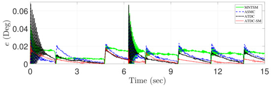
Figure 7.
Comparison of the tracking errors of MNTSMC [16] (dashed-line), ASMC [18] (dotted-dashed-line), the conventional ATDC [21] (solid-line), and the proposed ATDC-SM (dotted-line).

Table 1.
Root-mean-square (RMS) tracking errors of the conventional ATDC and the proposed ATDC-SM.
Figure 8 shows both the tracking and reference trajectories generated by the proposed ATDC-SM. The reference trajectory has a non-smooth point at approximately 7 s, which is a non-differentiable point. The non-differentiable point temporarily causes a large tracking error. However, the proposed ATDC-SM provides fast convergence rate with less fluctuations, as shown in Figure 7. Moreover, the proposed ATDC-SM has a similar level compared with the reference trajectory in the transient region, as shown in Figure 8.
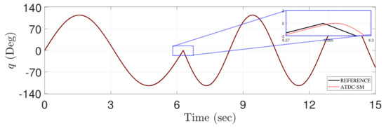
Figure 8.
Comparison of the tracking of reference trajectory (solid-line) and the proposed ATDC-SM (dotted-line).
4. Discussion
4.1. The Feasibility of the Proposed ATDC-SM in Two-Link Robot Manipulator
To determine the feasibility of the proposed ATDC-SM in multi-input–multi-output (MIMO) system, we have performed simulations through the system model of two-link robot manipulator. In this simulation, reference trajectories with non-differentiable point (Figure 9) was designed to be of both low and high frequencies. Two control approaches, i.e., the conventional ATDC [21] and the proposed ATDC-SM, have been applied to a two-link manipulator as an independent control method. Subsequently, all of their parameters are tuned in a low frequency trajectory.
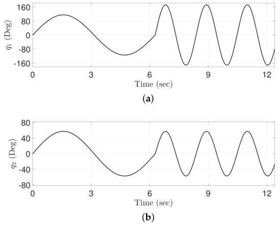
Figure 9.
Trajectories of the reference angles: (a) Joint 1; (b) Joint 2.
The system model of two-link robot manipulator [28] can be represented as follows:
where is the i-th joint angle, and , , are defined as , , and , respectively. The lengths of the links are chosen to be (cm) and (cm). Gravity acceleration is set to be (m/s), the friction coefficients are set to be . The loads of the joints 1 and 2 are given as (kg) and (kg), respectively. To the illustrate the effectiveness of the proposed ATDC, the conventional ATDC [21] is employed for comparison.
Additional simulation trajectories with non-differentiable point (Figure 9) are designed to be both low and high frequencies. All parameters of two control approaches are tuned in a low frequency trajectory. The simulation results are depicted in Figure 10, Figure 11 and Figure 12.
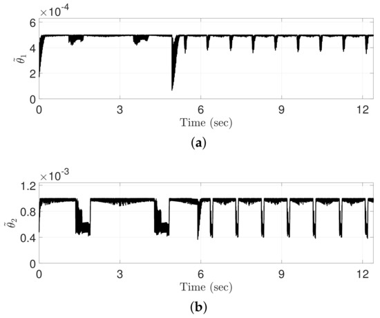
Figure 10.
Time-varying boundedness computed by the proposed ATDC-SM: (a) Joint 1; (b) Joint 2.
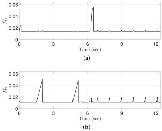
Figure 11.
Control gains computed by the proposed ATDC-SM: (a) Joint 1; (b) Joint 2.
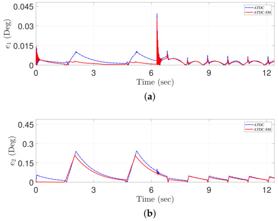
Figure 12.
Comparison of the tracking errors of the conventional ATDC [21] (dotted-line) and the proposed ATDC-SM (solid-line): (a) Joint 1; (b) Joint 2.
Figure 10 shows TVB computed by the proposed ATDC-SM. The TVB is inversely proportional to the magnitude of the sliding variables, and accordingly, the adaptive law in Equation (11) of the revised paper yields remarkable results. Actually, the TVB decreases if sliding variable moves away from sliding manifold, and hence, high control gains are achieved rapidly. Contrastingly, if the sliding variable is closer to the sliding manifold, the TVB should be increased to reduce the magnitude of the control gains rapidly. The effect of change on the TVB is shown in Figure 11.
Figure 11 shows the control gains generated by the proposed ATDC-SM. The control gains with TVB result in both high and low values with a fast adaptation speed. In particular, high control gains provide a fast convergence rate which results in precise tracking performance. However, the control gains may result in the excessive values that may cause undesired side effects, e.g., fluctuations and chattering. To avoid these problems, the control gains decrease rapidly owing to the increase in TVB, as shown in Figure 10. In other words, the TVB helps to reduce the control gains to maintain the system stability. The next figure shows that the proposed ATDC-SM is effective in achieving better tracking performance as compared with the conventional ATDC.
Figure 12 shows the tracking errors of two control approaches, including the conventional ATDC and the proposed ATDC-SM. The effect on the control gains generated by the adaptive law of Equation (11) with the TVB (seen in Figure 10) in the proposed ATDC-SM is significant. It can be observed that the fast convergence speed is provided around in 2 s, 5 s, 7 s, 8 s, 10 s, 11 s, and 14 s. Moreover, the proposed ATDC-SM provides more stable results without undesired side effects, such as chattering, compared with the existing control approach even at the point where no derivative is possible, i.e., at approximately 7 s.
Although the proposed ATDC-SM shows better tracking performance when compared with the conventional ATDC in two-link robot manipulator, applying the proposed one to the MIMO system with independent control may not guarantee global system stability. The proposed ATDC-SM needs to be designed to ensure the system stability in the MIMO system through a future work, and then it would be very meaningful to develop the proposed control-based approach to apply to the MIMO system.
4.2. The Performance of the Proposed ATDC-SM in One-Link Robot Manipulator With Irregular Reference Trajectory
The results of the following figures are compared with those of tracking errors in the Simulation Results of this paper. The simulation mathematical model is the same as one-link robot manipulator model seen in Equation (12).
Figure 13 shows reference trajectory of the low-to-high frequency with both non-differentiable point and variable amplitude, unlike Figure 2.
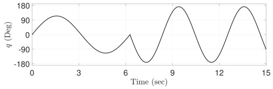
Figure 13.
Trajectory of the reference angle.
Figure 14 shows the tracking errors of four control approaches, i.e., MNTSMC [16], ASMC [18], the conventional ATDC [21], and the proposed ATDC-SM. As shown in Figure 2 and Figure 13, in reference trajectory between 0–7 s, the tracking errors of all control approaches in Figure 14 are also the same as those in Figure 7 because the reference trajectories of Figure 2 and Figure 13 are the same. However, the tracking errors shown in Figure 14 differ from those shown in Figure 7 around 7 s. As one of the differences, the tracking performance of the existing control approaches is significantly degraded in reference trajectory with non-differentiable point. They cause larger chattering and fluctuation around 7 s. On the other hand, the proposed ATDC-SM has good tracking performance without undesired side effects such as chattering. It implies that the proposed one shows better robust tracking performance than the existing control approaches. As another difference, since the reference trajectory provides large amplitude with high frequency in 7–15 s, the existing control approaches have slow convergence to the equilibrium point, and then the peak point for tracking errors is larger. On the other hand, the proposed ATDC-SM not only maintains fast convergence speed but also shows little change in peak point for tracking errors. RMS errors of all control approaches are shown in Table 2.
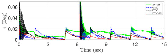
Figure 14.
Comparison of the tracking errors of the model-free nonsingular terminal sliding-mode control (MNTSMC) [16] (dashed-line), the adaptive sliding-mode control (ASMC) [18] (dotted-dashed-line), the conventional adaptive time-delayed control (ATDC) [21] (solid-line), and the proposed ATDC-SM (dotted-line).
Table 2.
RMS Tracking errors for reference trajectory with non-differentiable point.
Figure 15 shows both tracking and reference trajectories generated by the proposed ATDC-SM. Since the reference trajectory (Figure 13) has large amplitude, its slope changes rapidly at appropriately 7 s. However, the proposed one provides fast convergence rate with less fluctuations and hence has a similar level compared with the reference trajectory in transient region.
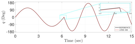
Figure 15.
Comparison of the tracking of reference trajectory (solid-line) and the proposed ATDC-SM (dotted-line).
The proposed ATDC-SM was based on the conventional ATDC that fully confirmed its applicability to the real robot manipulator in [21]. For this reason, although the effectiveness of the proposed ATDC-SM was verified quantitatively through simulation based on robot manipulator model, we believe that the proposed ATDC-SM can be applied to real robot manipulators.
5. Conclusions
In this paper, an ATDC-SM scheme was proposed with a new adaptive law for the control gain to enjoy the benefits of ATDC. The update parameter automatically created a region in which the control gain increases or decreases. From this benefit, the control gain of the proposed ATDC-SM scheme could be adjusted appropriately and hence provided a fast adaptation speed for achieving a high or low control gain. The tracking error was guaranteed to be uniformly ultimately bounded without the undesired side effects such as chattering or fluctuation. Its effectiveness was shown through simulation in which the proposed one produced remarkably good tracking performance, regardless of its simple structure.
The proposed ATDC-SM was designed to be applied to a one-link robot manipulator. The proposed ATDC-SM was restricted to SISO systems, and thus it is necessary to develop control approaches with a new adaptive law based on the proposed TVB that can be applied to MIMO systems. We believe that these approaches will be regarded as remarkable control approaches in the future.
Author Contributions
Conceptualization: J.B.; software: J.B.; data curation: J.B.; writing—original draft preparation: J.B; writing—review and editing: J.B. and H.B; supervision: H.B.; project administration: H.B.; funding acquisition: H.B. All authors have read and agreed to the published version of the manuscript.
Funding
This work was supported by the National Research Foundation of Korea (NRF) grant funded by the Korea government (No. 2019R1F1A1059663).
Conflicts of Interest
The authors declare no conflict of interest.
Appendix A
Stability Analysis
We consider the Lyapunov function as below:
The time derivative of Equation (A1) can be computed as
Substituting Equation (9) into Equation (A3) yields
where the TDE error is bounded as according to Lemma 1. and . Then, can be summarized by adding as follows:
where . Substituting Equation (A5) into Equation (A4), we have
where and . is bounded from the reasonable assumption, i.e., for a certain positive value . If the switching gain can be chosen to be
resulting in
Multiplying both sides of Equation (A2) by , we have
Solving for yields
Substituting Equation (A10) into Equation (A8), it follows that
From Equation (A11), it can be represented as below:
For , it follows that
For any positive , the Lyapunov function decreases with a non-zero speed if where . It implies that the sliding variable enters the set within a finite time . The sliding variable exists then within the set , and the Lyapunov function of Equation (A1) has an upper bound :
where .
From Equation (A14), it shows that the sliding variable is UUB for as follows:
Although the sliding variable moves in and out of the small vicinity of the sliding manifold due to the attractivity, it is guaranteed to be uniformly ultimately bounded in Equation (A15). Additionally, from Equation (8), the tracking error is also proved to be bounded.
References
- Chan, S.; Liaw, H. Generalized impedance control of robot for assembly tasks requiring compliant manipulation. IEEE Trans. Ind. Electron. 1996, 43, 453–461. [Google Scholar] [CrossRef]
- Lee, W.; Shih, C. Control and breakthrough detection of a three-axis robotic bone drilling system. Mechatronics 2006, 16, 73–84. [Google Scholar] [CrossRef]
- Naito, J.; Obinata, G.; Nakayama, A.; Hase, K. Development of a wearable robot for assisting carpentry workers. Int. J. Adv. Robot. Syst. 2007, 4, 431–436. [Google Scholar] [CrossRef]
- Shin, W.; Kwon, D. Surgical robot system for single-port surgery with novel joint mechanism. IEEE Trans. Biomed. Eng. 2013, 60, 937–944. [Google Scholar] [CrossRef] [PubMed]
- Das, A.; Zhang, P.; Lee, W.; Popa, D.; Stephanou, H. μ 3: Multiscale, deterministic micro-nano assembly system for construction of on-wafer microrobots. In Proceedings of the 2007 IEEE International Conference on Robotics and Automation, Roma, Italy, 10–14 April 2007; pp. 461–466. [Google Scholar]
- Piltan, F.; Yarmahmoudi, M.; Shamsodini, M.; Mazlomian, E.; Hosainpour, A. PUMA-560 robot manipulator position computed torque control methods using Matlab/Simulink and their integration into graduate nonlinear control and Matlab courses. Int. J. Robot. Autom. 2012, 3, 167–191. [Google Scholar]
- Islam, S.; Liu, P. Robust sliding mode control for robot manipulators. IEEE Trans. Ind. Electron. 2011, 58, 2444–2453. [Google Scholar] [CrossRef]
- Sharifi, M.; Behzadipour, S.; Vossoughi, G. Nonlinear model reference adaptive impedance control for human–robot interactions. Control Eng. Prac. 2014, 32, 9–27. [Google Scholar] [CrossRef]
- Huh, S.; Bien, Z. Robust sliding mode control of a robot manipulator based on variable structure-model reference adaptive control approach. IET Control Theory Appl. 2007, 1, 1355–1363. [Google Scholar] [CrossRef]
- Chien, M.; Huang, A. Adaptive control for flexible-joint electrically driven robot with time-varying uncertainties. IEEE Trans. Ind. Electron. 2007, 54, 1032–1038. [Google Scholar] [CrossRef]
- Baek, S.; Baek, J.; Han, S. An Adaptive sliding mode control with effective switching gain tuning near the sliding surface. IEEE Access 2019, 7, 15563–15572. [Google Scholar] [CrossRef]
- Lee, J.; Yoo, C.; Park, Y.; Park, B.; Lee, S.; Gweon, D.; Chang, P. An experimental study on time delay control of actuation system of tilt rotor unmanned aerial vehicle. Mechatronics 2012, 22, 184–194. [Google Scholar] [CrossRef]
- Wang, Y.; Yu, D.; Kim, Y. Robust time-delay control for the DC–DC boost converter. IEEE Trans. Ind. Electron. 2014, 61, 4829–4837. [Google Scholar] [CrossRef]
- Park, B.; Kim, T.; Tahk, M. Time-delay control for integrated missile guidance and control. Int. J. Aeronaut. Space Sci. 2011, 12, 260–265. [Google Scholar] [CrossRef]
- Han, D.; Chang, P. Robust tracking of robot manipulator with nonlinear friction using time delay control with gradient estimator. J. Mech. Sci. Technol. 2010, 24, 1743–1752. [Google Scholar] [CrossRef]
- Jin, M.; Lee, J.; Chang, P.; Choi, C. Practical nonsingular terminal sliding-mode control of robot manipulators for high-accuracy tracking control. IEEE Trans. Ind. Electron. 2009, 56, 3593–3601. [Google Scholar]
- Bae, H.; Jin, M.; Suh, J.; Lee, J.; Chang, P.; Ahn, D. Control of robot manipulators using time-delay estimation and fuzzy logic systems. J. Elect. Eng. Technol. 2017, 12, 1271–1279. [Google Scholar] [CrossRef]
- Baek, J.; Jin, M.; Han, S. A new adaptive sliding-mode control scheme for application to robot manipulators. IEEE Trans. Ind. Electron. 2016, 63, 3628–3637. [Google Scholar] [CrossRef]
- Cho, S.; Jin, M.; Kuc, T.; Lee, J. Stability guaranteed auto-tuning algorithm of a time-delay controller using a modified Nussbaum function. Int. J. Control 2014, 87, 1926–1935. [Google Scholar] [CrossRef]
- Jin, M.; Lee, J.; Tsagarakis, N.G. Model-free robust adaptive control of humanoid robots with flexible joints. IEEE Trans. Ind. Electron. 2016, 64, 1706–1715. [Google Scholar] [CrossRef]
- Baek, J.; Cho, S.; Han, S. Practical time-delay control with adaptive gains for trajectory tracking of robot manipulators. IEEE Trans. Ind. Electron. 2018, 65, 5682–5692. [Google Scholar] [CrossRef]
- Khalil, H. Nonlinear Systems; Pearson: Upper Saddle River, NJ, USA, 2002. [Google Scholar]
- Spong, M.; Hutchinson, S.; Vidyasagar, M. Robot Modeling and Control; Wiley: Hoboken, NJ, USA, 2005. [Google Scholar]
- Youcef-Toumi, K.; Ito, O. A time delay controller for systems with unknown dynamics. Trans. ASME J. Dyn. Syst. Meas. Control 1990, 112, 133–142. [Google Scholar] [CrossRef]
- Hsia, T.; Lasky, T.; Guo, Z. Robust independent joint controller design for industrial robot manipulators. IEEE Trans. Ind. Electron. 1991, 38, 21–25. [Google Scholar] [CrossRef]
- Utkin, V. Sliding mode control design principles and applications to electric drives. IEEE Trans. Ind. Electron. 1993, 40, 23–36. [Google Scholar] [CrossRef]
- Armstrong, B. Friction: Experimental determination, modeling and compensation. In Proceedings of the 1988 IEEE International Conference on Robotics and Automation, Philadelphia, PA, USA, 24–29 April 1988; pp. 1422–1427. [Google Scholar]
- Craig, J. Introduction to Robotics: Mechanics and Control; Pearson Prentice Hall: Upper Saddle River, NJ, USA, 2005. [Google Scholar]


© 2019 by the authors. Licensee MDPI, Basel, Switzerland. This article is an open access article distributed under the terms and conditions of the Creative Commons Attribution (CC BY) license (http://creativecommons.org/licenses/by/4.0/).