Article

Motion Control and External Force Estimation of a Pneumatically Driven Multi-DOF Robotic Forceps

1
Institute of Innovation Research, Tokyo Institute of Technology, 4259 Nagatsuta-cho, Yokohama, Kanagawa 226-8502, Japan
2
Department of Mechanical Engineering, Tokyo National College of Technology, 1220-1, Kunugida-machi, Hachioji, Tokyo 193-0997, Japan
*
Author to whom correspondence should be addressed.
Appl. Sci. 2020, 10(11), 3679; https://doi.org/10.3390/app10113679
Submission received: 25 April 2020 / Revised: 21 May 2020 / Accepted: 25 May 2020 / Published: 26 May 2020
(This article belongs to the Section Mechanical Engineering)

Abstract

:

Featured Application

The system can be used as an end effector for a robotic-assisted surgery, which is able to provide information of interaction force with the working environment.

Abstract

Robotic forceps with a rigid-link joint mechanism is orthodox for current robotic-assisted surgery systems. However, external force estimation without force sensors during operations is difficult for such electrically driven forceps. This work introduces a pneumatically driven multi-DOF (DOF: degree of freedom) forceps using a rigid-link mechanism with less interference of the wire drive between joints and realizes external force estimation by utilizing high back-drivability of pneumatic cylinders. We developed a position controller with dynamic compensation of the mechanical friction, in which the rotational angles of the three movable joints of the forceps are independently controlled. Moreover, we designed an external force observer in the position controller by applying the disturbance observer scheme. The results of the performance evaluation experiments are as follows. First, in the joint position control experiments, smooth and stable controllability is confirmed for sinusoidal reference inputs with the mean absolute errors of less than 2°. The resolution of the joint position control is approximately 1° for the response of step increasing reference inputs, which is acceptable for laparoscopic surgery. Second, the external force observer can correctly estimate the translational and the grasping forces with less than 20% errors of the maximum output forces. The practical sensitivities of the external force estimation are better than 0.5 N for translational forces and 0.2 N for grasping forces. The achieved performance of the developed forceps can be applicable for interactive force control in some particular surgical tasks such as suturing, ligation, organ traction and exclusion.

1. Introduction

Robotic-assisted minimally invasive surgery has been significantly developed owing to its many benefits, including the reduction of the surgeon’s tremble and increase in the operational accuracy [1,2]. As the end effector of a robotic-assisted surgery system, the robotic forceps are inserted into the patient’s abdominal cavity through a trocar. Hence, the size of the working part is firmly restricted.
Several groups used the rigid-link mechanism to meet such requirements, wherein multiple rigid joint links independently rotate in a direction that is orthometric with the others, and the actuators are located at the proximal end outside the patient’s body. Song et al. developed a forceps with four DOF [3]. Additionally, Andreas et al. proposed a snakelike instrument that consists of seven rigid joints for minimally invasive surgery [4].
The abovementioned devices all use electrical motors with a high reduction ratio and can realize accurate position control performance. On the other hand, the force control and sensing capabilities at the forceps part are also relevant and vital for high operational performance and safety. For example, knowing the real-time output force can help surgeons use an appropriate force to manipulate the organ [5], suture the incision [6], and do bone biopsy [7]. Moreover, the force-sensing function at the end effector is essential to realize haptic feedback [8], which is a challenging and effective improvement to the surgical robots.
A standard method is embedding force sensors at the distal end of the forceps like the conventional manipulators [9,10,11]. However, the size of the force sensors hinders the miniaturization of the forceps, and the temperature and humidity of the working environment interfere with the accuracy of the force sensors. Takahashi et al. developed a robotic forceps with strain gauges located at the shaft part of the forceps [12]. The working environment would not interfere with the accuracy of the force sensors, and the strain gauges did not increase the size of the distal end. However, this mechanism could not show the grasping force. Soek et al. developed miniature force sensors embedded at the two fingers of the gripper [13] and proposed an algorithm to compensate for the effect of the temperature and humidity [14]. However, the miniature force sensors were expensive to the limited time of reusing the forceps.
Disturbance observer is a helpful control scheme for sensorless force estimation [15]. However, all the current devices use electrical motors, wherein the high reduction ratio of their actuators hinders the estimation of the tiny external forces that arise in many surgeries. Series elastic actuator (SEA) is a classical method to realize force estimation and output force control when using electrical motors, and is commonly applied in the human interactive devices such as the exoskeleton and prosthesis. However, it is difficult to make this complicated mechanism compact for a robotic forceps.
Pneumatic drive, which has a higher power-weight ratio than electrical actuation, is an effective solution for this problem. Due to the high back-drivability of the pneumatic cylinders, the tiny external forces can be estimated from the air pressure exerted on the cylinder heads by using the disturbance observer scheme. Moreover, the ease of obtaining and the cleanness of the air source make pneumatic drive suitable for a surgery device than other back-drivable actuations such as hydraumatic driven. Miyazaki et al. developed a pneumatically driven robotic forceps that can estimate the external forces [16]. However, the undesirable deformation of the snakelike flexible joint in the case of large external loads was still a problem, and the magnitude of the output force was limited.
The Da Vinci system adopts a rigid-link mechanism wherein the tip joint simultaneously controls the joint bending and gripping motions [17]. This layout is considered to be optimal and orthodox for surgeries in narrow spaces because it considerably reduces the size of the end effector, and the output force is large enough for surgery. However, the forceps used in the Da Vinci system cannot realize external force estimation without force sensors due to its electrical actuation. Furthermore, motion interference between the forceps joints due to the wire drive mechanism is also an issue for accurate force estimation.
Therefore, in this work, we propose a pneumatically driven robotic forceps using a rigid-link mechanism with less motion interference between the joints. The main contributions of this work are as follows. First, we built a motion controller for a pneumatically driven robotic forceps. Second, we proposed an external force estimation scheme by taking advantage of back-drivability of the pneumatic cylinders. Third, we implemented experiments to testify the performance of motion control and external force estimation. In Section 2, we briefly introduce the forceps mechanical design. Section 3 describes the control system including the kinematics and dynamics modeling, wherein the force estimation scheme is introduced. Section 4 demonstrates the performance of motion control and force estimation.

2. Pneumatically Driven Robotic Surgical Forceps

Figure 1 presents the appearance of the developed forceps. It mainly comprises of the forceps part and the driving part.

2.1. Overview of the Forceps

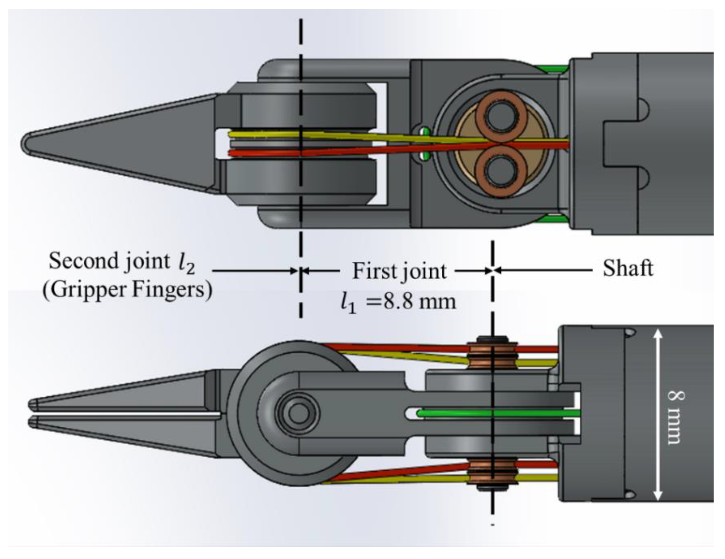
The forceps part comprises of a shaft, a joint link and a gripper. The diameter of the shaft is 8 mm, and its length is 300 mm. The diameters of the gripper fingers and the joint link are not more than that of the shaft. Figure 2 presents the distal end of the forceps part in detail. The length of the first joint is 8.8 mm, and its rotation range is ±90°. The second joint consists of two gripper fingers, which simultaneously determine the bending motion of the second joint and the grasping motion of the gripper while independently controlling the two co-axial gripper fingers.
The driving part consists of three pneumatic cylinders (CJX2B10–15RZ, SMC Corp., Tokyo, Japan) with position sensors (RDC1014A09, Alps Alpine Co., Ltd., Tokyo, Japan). Each cylinder directly transmits the actuation force to the corresponding moving part on the forceps tip via stainless driving wire (the yellow, red and green wires in Figure 2).

2.2. The Interference Reduction Mechanism

When the first joint rotates, the wires connected to the gripper fingers (the yellow and red wires in Figure 2) should pass the rotation center of the first joint without shifting of the wire route, which seriously affects the control accuracy. Jinno designed an arc-shaped wire guide to keep the wire route [18]. However, the friction between the wire and the guide is a problem.
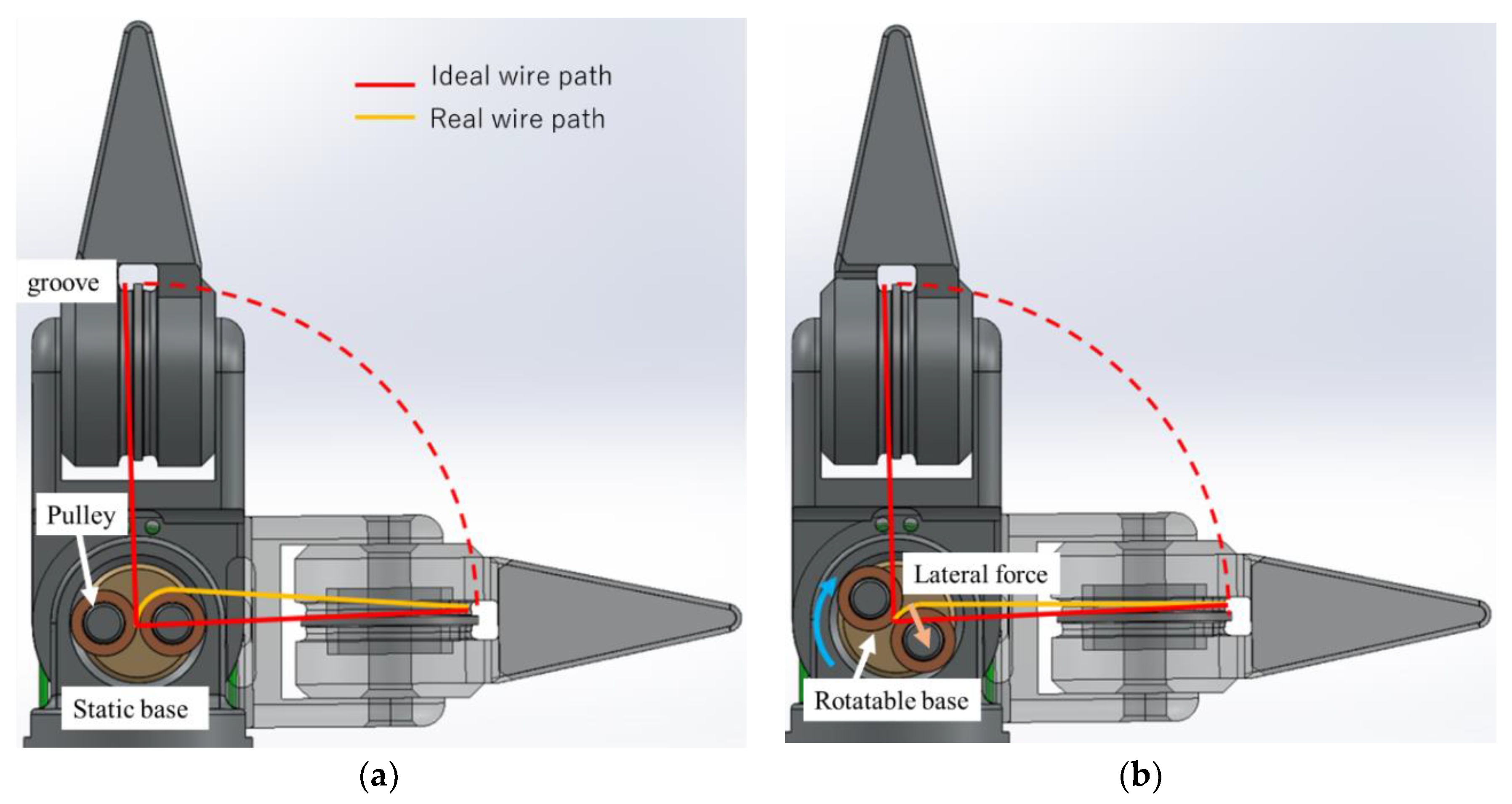
Therefore, we set a pair of pulleys to guide the routes of the yellow and red wires to pass the rotation center of the first joint and can reduce the friction. The manner in which the pulleys guide the wires is shown in Figure 3.
However, when the first joint rotates, the real wire path is different from the ideal one because of the size of the pulleys, as shown in Figure 3a. Hence, the wire from the rotating center to the groove of the second joint was stretched. The wire tension and the additional friction to the groove resulted from the stretching affects the control performance.
Therefore, we designed the rotatable pulley base (depicted as the “Rotatable base” in Figure 3b. The pulley base can passively rotate by the lateral force from the wire when the first joint rotates. This mechanism reduces the variations in the path of the wires to 1/4 of that in cases of using a static pulley base, as presented in Figure 3a.
This mechanism cannot only reduce the interference, but also reduces the friction between the wire and the guide.

3. Control Scheme

3.1. Kinematics

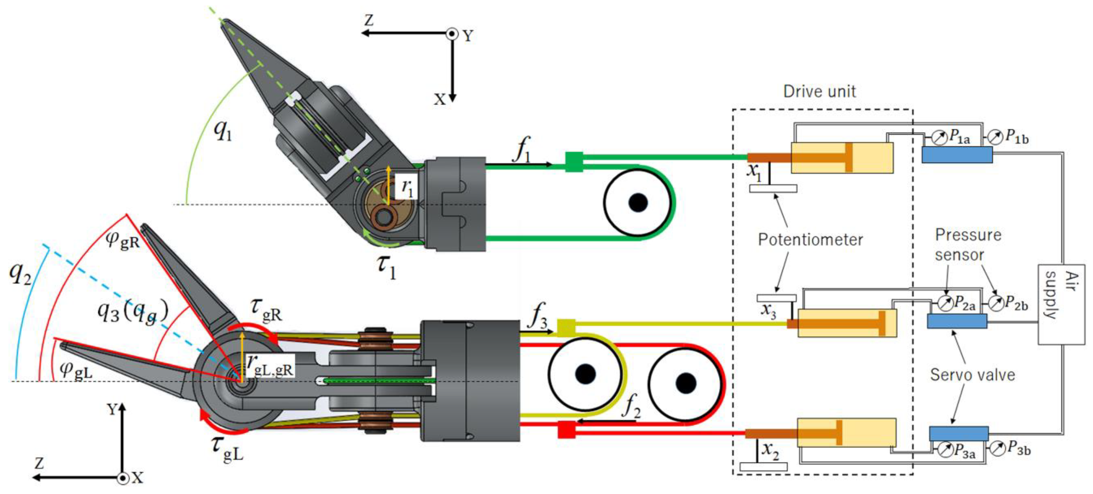
Figure 4 presents the schematic of the driving system, including the coordinate system. Forceps motion angles q = ( q 1 , q 2 , q 3 ) T are intuitively used to represent the motion of the whole forceps, where q 1 and q 2 respectively denote the bending angles of the first and the second joints, and q 3 denotes the open angle of the gripper.
As shown in Figure 4, the rotational angles of the two gripper fingers ( φ gL and φ gR ) determine both q 2 and q 3 by independently controlling the two gripper fingers. Hence, in this work, we used the mechanical joint angles φ = ( φ 1 , φ gL ,   φ gR ) T   instead of the forceps motion angles q for motion control. The relationship between the forceps motion angles q and the mechanical joint angles φ can be geometrically expressed as follows:
q = [ q 1 q 2 q 3 ] = J link φ = [ 1 0 0 0 1 / 2 1 / 2 0 1 1 ] [ φ 1 φ gL φ gR ]
J link is the Jacobian matrix that translates the mechanical joint angles φ to the forceps motion angles q . As mentioned in Section 2, we used three pneumatic cylinders as actuators with linear actuation motions. The actuator displacements x = ( x 1 , x 2 , x 3 ) T denote the linear positions of each cylinder rod, which are measured by the potentiometers (RDC1010A12, Travel: 10 mm, Alps Alpine Co., Ltd., Tokyo, Japan) connected to the cylinder rods shown in Figure 4. Additionally, the relationship between x and φ is expressed by the following equation:
φ = [ φ 1 φ gL φ gR ] = J x x = [ 1 r 1 0 0 0 1 r gL 0 0 0 1 r gR ] [ x 1 x 2 x 3 ]
where the Jacobian matrix J x   in (2) translates the displacement of the cylinder rods x to the mechanical joint angles φ . Parameters r 1 , r gL ,   r gR in J x represent the radius of the wire path about the joint rotation center, as presented in Figure 4.
Moreover, the relationship between the driving force output by each cylinder f cyl = ( f 1 , f 2 , f 3 )   and the torque of each mechanical joint τ φ = ( τ 1 , τ gL , τ gR ) can be expressed as (3) using the principle of virtual work.
τ φ = ( J x T ) 1 · f cyl

3.2. Dynamics

The dynamic models of the mechanical joints Z = { Z 1 ,   Z gL , Z gR } are expressed by the following functions.   Z 1 is the dynamics of the first link, and Z gL and Z gR are the dynamics of the two grip fingers.
Z i = { C i φ ˙ i + D i sgn ( φ ˙ i ) ( i = 1 ) C i φ ˙ i + D i sgn ( φ ˙ i ) e 2 μ | q 1 | ( i = gL   and   gR )
The first terms are viscous frictions from the pneumatic fluid dynamics. The second terms are Coulomb frictions mainly generated from the actuation wires and the other moving parts of the joint mechanism (shaft, pulley, etc.). Regarding the gripper fingers ( i =   φ gL and φ gR ), values of the mechanical Coulomb friction change according to the rotated angle of the first joint ( q 1 or φ 1 ), which is caused by the change of the contact condition between the actuation wires and their guiding pulleys. Herein, we used the theory of the friction transmission proposed by Euler [19] to model a nonlinear friction by multiplying an exponential factor related to the angle of the first joint to the Coulomb friction. Note that the inertia of each joint can be omitted due to their lightweight.
Table 1 lists the dynamics model parameters used in the control system in this work, which were determined by trial and error. First, we determined D i to identify the Coulomb friction by conducting low speed motion on each joint. Then, we determined C i to identify the viscous friction by conducting high speed motion on each joint. The nonlinear friction appears when the rotation angles of the first joint are large. Hence, we determined the parameter of μ when the first joint rotates at large angles.

3.3. External Force Estimation

We estimated the external force exerted on the tip of the forceps by using the disturbance observer control scheme.
If there is no external force, the driving torque of the joints is equal to their dynamics. The external force exerted on the tip of the forceps works as a torque ( τ φ _ ext ) to each mechanical joint expressed by the mechanical joint angles φ . The relationship between τ φ _ ext and the driving torque of the mechanical joint τ φ is expressed by the following function:
τ φ Z = τ φ _ ext
The forceps motion angle q is more intuitive to represent the motion of the whole forceps. Hence, it is more appropriate for calculating the external force to use the converted torque parameter τ q about the forceps motion angle q . By using the principle of virtual work on (1), τ q can be calculated by the following function:
τ q = ( J link T ) 1 τ φ = [ 1 0 0 0 1 1 0 1 / 2 1 / 2 ] τ φ
We herein denote τ q _ ext = ( τ q 1 ext ,   τ q 2 _ ext ,   τ q 3 _ ext ) T as the external torque about the motion angle q . Then, τ q _ ext can be calculated from τ φ _ ext by using the same relationship expressed by (6).
τ q _ ext = ( J link T ) 1 τ φ _ ext
In this work, we separately estimate the external translational force f ext on the forceps tip and the external grasping force f ext _ g on the gripper. The three components of f ext in the orthogonal coordinate system presented in Figure 4 are calculated from the two joint torque components in τ q _ ext by using the Jacobian matrix of a 2-DOF serial link mechanism as follows.
f ext = [ f ext _ x f ext _ y f ext _ z ] = ( J a T ) + τ q 12 _ ext = [ 0 1 ( l 1 + l 2 ) cos q 1 1 l 2 cos q 2 0 1 ( l 1 + l 2 cos q 2 ) sin q 1 1 l 2 sin q 2 ] [ τ q 1 _ ext τ q 2 _ ext ]
J a is the Jacobian matrix of a 2-DOF serial link manipulator, which translates the angular velocity of the two serial link joints to the translational velocity of the end effector in Cartesian coordinates.   τ q 12 _ ext = ( τ q 1 ext ,   τ q 2 _ ext ) T is a 2-DOF vector consisting of the first two elements of τ q _ ext . l 1 denotes the length of the first joint and l 2 denotes the length from the tip at the gripper finger to its rotation center as presented in Figure 2.
Regarding the grasping force, we used the third element of τ q _ ext , which can be calculated as follows:
f ext _ g = 1 l 2 τ q 3 _ ext

3.4. Control System

We implemented the abovementioned external force observer in the position controller of the forceps, as presented in Figure 5. The subscripts “ref” and “mea” indicate the reference and measured values of the corresponding parameters, respectively. This system constitutes a cascade controller including a minor control loop of the pneumatic force controller. Figure 6 shows the block diagram of the pneumatic force controller, where u is the input voltage to the servo valve. Cylinder driving forces are determined based on the pressures P a and P b measured by pressure sensors (PSE510-R06, operating pressure range: 1MPa, SMC Corp., Tokyo, Japan) to the two sides of the piston, and the cross-sectional areas A a and A b of the two sides of the piston. Table 2 lists the feedback gains in the controllers.

4. Performance Evaluation

4.1. Position Control Performance

We conducted position control experiments of the forceps using the designed control system.
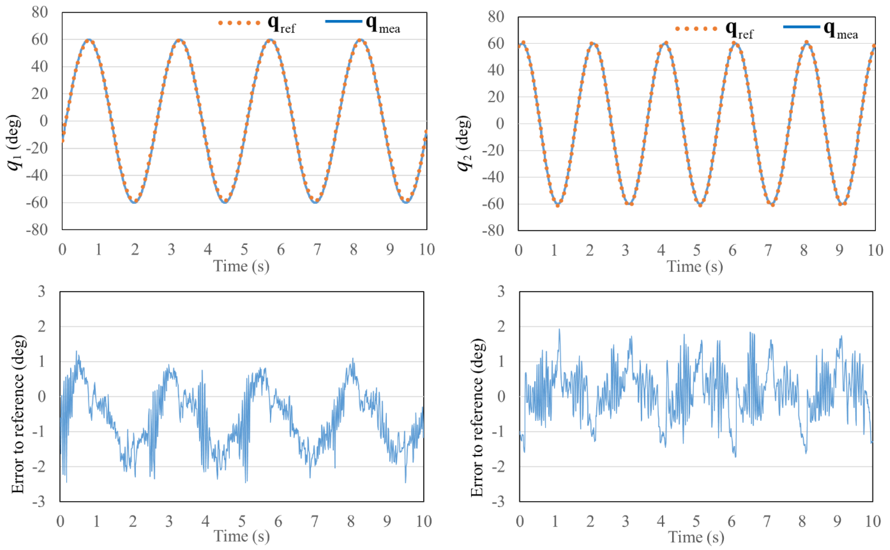
First, the joint positions were controlled with sinusoidal reference inputs. Figure 7 presents the time responses of q 1 and q 2 when the first and second joints were simultaneously driven. The input reference angles of q 1 and q 2 were sinusoidal functions with an amplitude of 60° and frequencies of 0.4 Hz and 0.5 Hz, respectively. These motions cover the average rotational velocities for the commonly used forceps in laparoscopic surgeries. The results presented in Figure 7 reveal that the joint angles of the forceps can exactly follow the references. The maximum errors of the measured joint angles in comparison with the reference angles were both approximately 2°, whereas the mean absolute errors of q 1 and q 2 were 0.87° and 0.59°, respectively. Moreover, the performance of the position control of q 2 indicates that the motion of the first joint did not interfere with that of the second joint. The interference reduction mechanism introduced in Section 2.2 was validated to work quite effectively.
Next, we investigated the maximum resolution of the joint position control. In this experiment, the joint positions were controlled where the reference inputs were step functions whose values increase every second. According to the experimental results shown in Figure 8, the maximum positioning resolution was about 1° for both q 1 and q 2 .

4.2. External Force Estimation Performance

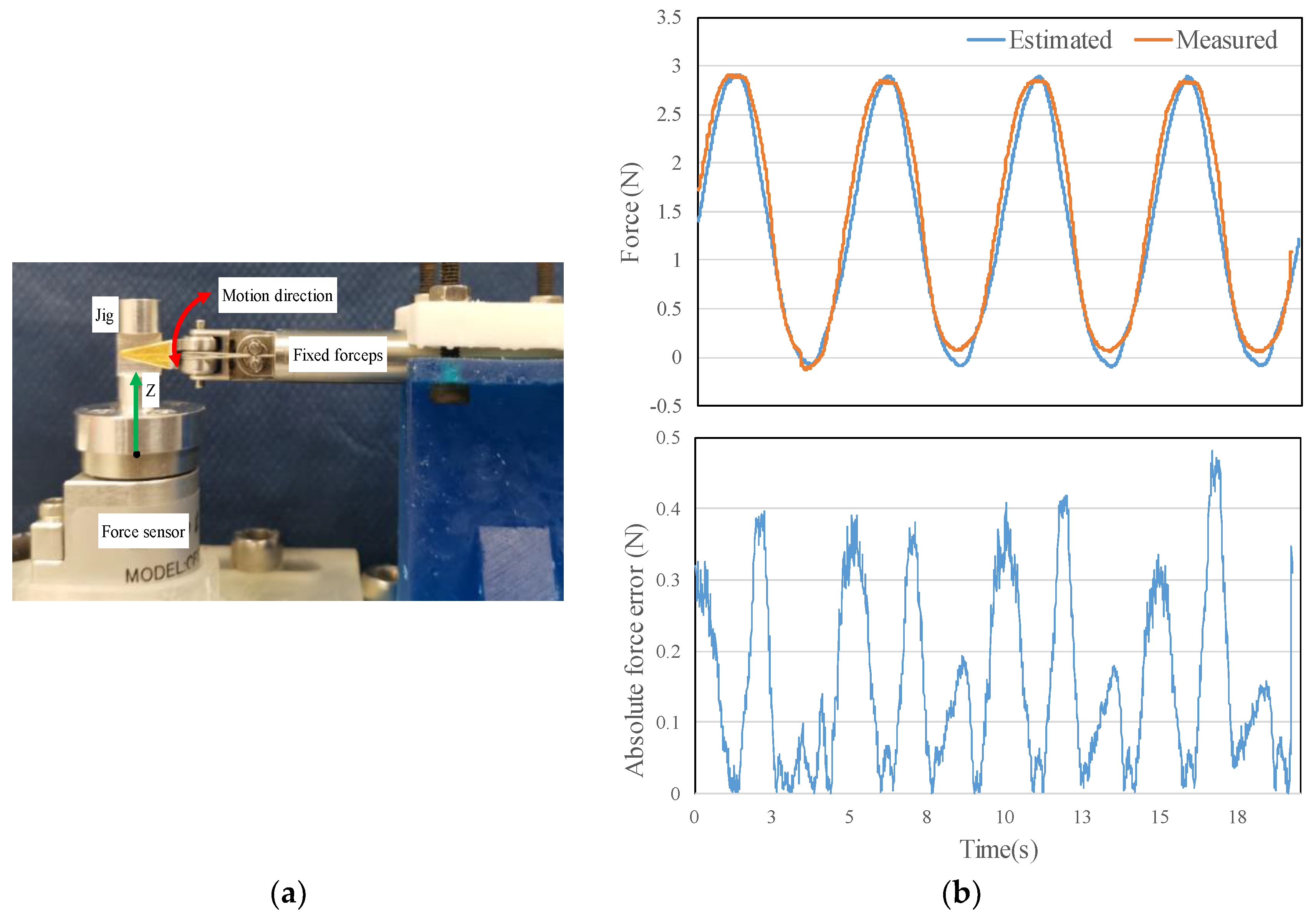
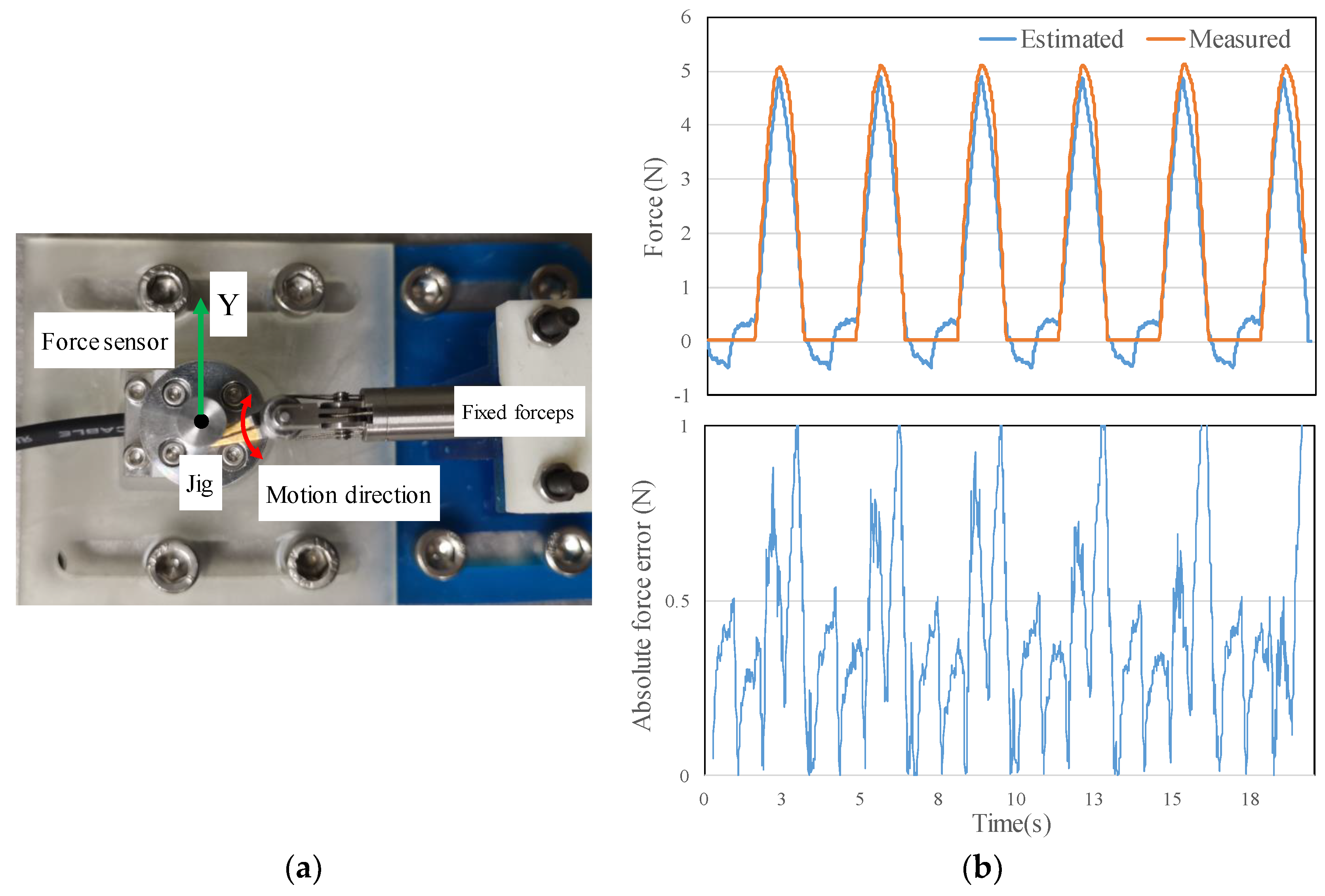
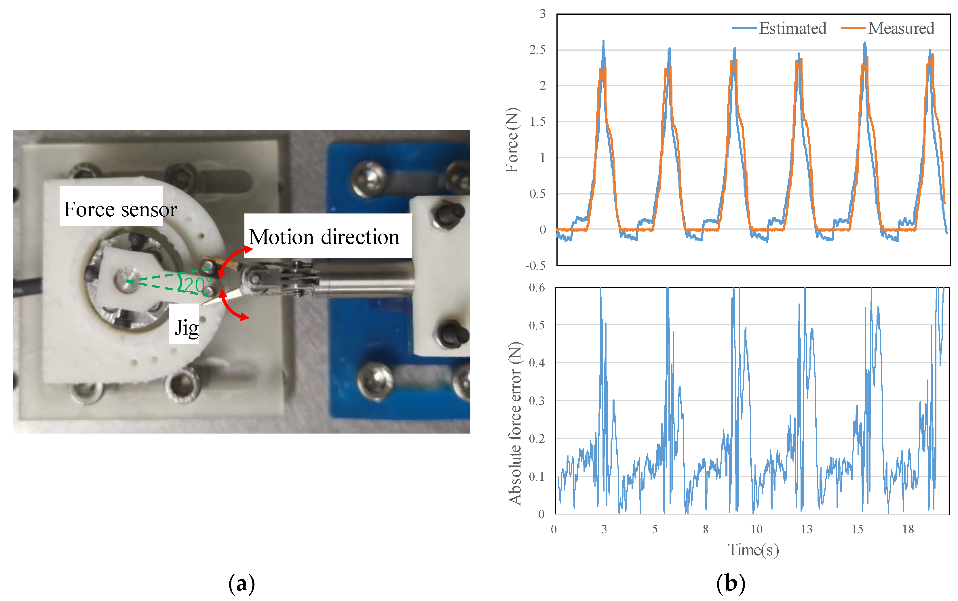
We evaluated the performance of the external force estimation by experiments. In the experiments, the forceps gripper was to apply joint driving forces to a jig connected to a force sensor (CFS018CA101U, Leptrino Corp., Nagano, Japan) as shown in Figure 9, Figure 10 and Figure 11. The force sensor measured the interaction forces and the external force observer in the control system also estimated those. Then, we evaluated the performance of external force estimation by comparing the estimated and measured forces.
Figure 9a presents the experimental setup for evaluating the external force estimation in the Z-axis direction. Driving force from the joint q 1 was applied to the jig, and the force was generated by a sinusoidal position control input for q 1 (amplitude: 30°, frequency: 0.2 Hz). Figure 9b presents the comparison of the estimated and the measured forces on the Z-axis, and the absolute value of the error between them. It can be seen that the estimated force was close to the real force measured by the force sensor. The maximum error was 0.48 N, and the average error was 0.16 N.
Second, we evaluated the external force estimation in the Y-axis direction as presented in Figure 10a. Driving force from the joint q 2 was applied to the jig in the rightward, and the force was generated by a sinusoidal position control input for q 2 (amplitude: 30°, frequency: 0.3 Hz). Figure 10b presents the comparison of the estimated and measured forces on the Y-axis, and the absolute value of the error between them. The estimated force was mainly close to the real force measured by the force sensor, while different response trend was observed when the measured force was 0 N. The maximum error was 1.0 N, and the average error was 0.40 N.
Finally, we evaluated the performance of the grasping force estimation. Figure 11a presents the experimental setup. Grasping force was applied to the jig, and the force was generated by a sinusoidal position control input for q 3 , the open angle of the gripper (amplitude: 30°, frequency: 0.3 Hz). The jig prevented the gripper fingers from closing, then the force sensor measured the closing moment of the gripper fingers, and the real grasping force was calculated by multiplying the length from the contact point to the center of the force sensor. Figure 11b presents the comparison of the estimated grasping force and the measured one, and the absolute value of the error between them. It can be observed that the estimated grasping force was mainly close to the real force measured by the force sensor, while different response trend was observed when the measured grasping force was 0 N or just beyond the reference peak. The maximum error was 0.60 N, and the average error was 0.17 N.

5. Discussion

The performance of the position control system demonstrated that smooth and stable motion could be realized. Furthermore, the position control resolution is 1° about the joint angles, which is the same level with the pneumatically driven forceps with a flexible joint [16]. This position control resolution is acceptable for a master-slave robotic-assisted system for laparoscopic surgery [20]. In Figure 8, the chattering in the curves of the measured joint positions come from the measurement noise of the potentiometers, and it can be reduced by using the encoders as the position sensor.
Regarding the performance of external force estimation, the maximum errors between the estimated and measured forces in all directions were less than 20% of the maximum output forces. The level of force estimation accuracy is same with that of a motor actuated forceps using strain gauges located at the shaft to calculate the force [12], and the pneumatically driven forceps with a flexible joint [16]. The maximum error in the force estimation appeared when the measured forces were near the peak, as shown in Figure 9, Figure 10 and Figure 11. These estimation errors are mainly caused by the modeling uncertainties of the forceps joint dynamics. In particular, static frictions of the forceps mechanism and elongation of the driving wires can be critical factors to deteriorate the performance of the force estimation. Additionally, Figure 10 and Figure 11 show that characteristic estimation errors appeared when the measured forces were 0 N. At this moment, the forceps joints moved freely and did not interact with the jig, and the joint moving directions were changed to the opposite side. The reason of the estimation errors was the dynamic modeling uncertainties of the forceps; the coulomb friction term (shown in Equation (4)) was slightly overestimated. According to the experimental results, the minimum detectable forces considering the estimation errors (i.e., the practical sensitivity of force estimation) are less than 0.5 N for translational forces regarding the joints q 1 and q 2 , and about 0.2 N for grasping forces regarding the joint q 3 . Although it is difficult to completely cancel these estimation errors, the accuracy of external force estimation achieved in this work will be helpful to enhance the safety in particular surgical operations such as cutting, suturing, ligation, organ traction and exclusion.
Moreover, the maximum translational force of this forceps covers the required force magnitude for the suturing operation in laparoscopic surgery, which is 1–2 N [21]. Regarding the grasping force, the maximum grasping force of this device is five times larger than the forceps introduced in [16], additional experiment with the real organs is necessary to justify whether this magnitude of grasping force is sufficient.
The air in the pneumatic cylinders is compressible, and the route of tubes may bring delay between the controller commands and the device motion. A previous study of our group have testified that the delay is about 6 ms [22], which is negligibly small compared to the human hand operation in the master–slave system. Regarding the influence from the change in temperature and humidity, first, we used the differential pressure rather than the absolute pressure between the two sides of the piston to control the output forces of the cylinders. Hence, the change of temperature will not affect the controllability. Second, the result of an in-vivo experiment using another pneumatically driven forceps proposed by our group demonstrated that the intra-abdominal environments did not affect the position control performance, and the body fluids did not exert any adverse effects in force handling [23].
This paper focused on estimating the external force applied on the tip joints that execute most of the motions in the operation. However, when doing robotic-assisted surgery, the organs or tissues inside the patient’s body may not only interact with the tip joints, but also with the shaft. The interaction force applied on the shaft should also be considered for the accuracy of external force estimation. When doing robotic-assisted surgery, the robotic forceps is installed on a robotic holder, and the force applied on the shaft can be measured by a force sensor mounted on the holder. It is acceptable to use a force sensor because its attachment place is outside the patient body and the robotic holder is reusable. The accuracy of the force estimation at the tip joints could be compensated by using the force measured by the sensor. External force estimation after installing the robotic forceps on a robotic holder will be reported in future works.

6. Conclusions

In this work, we developed a pneumatically driven robotic forceps capable of external force estimation. The working part of the forceps is a rigid-link joint mechanism whose gripper fingers simultaneously determine the bending motion of the second joint and the grasping motion. The interference reduction mechanism of wire driven joints was designed, which was validated to work quite effectively.
The motion control system is a cascade controller in which we correctively modeled the friction terms of the pneumatic driving system and the wire actuation mechanism as the dynamics of the forceps. The results of the position control experiments revealed that the positioning accuracy of the forceps joints could be acceptable for laparoscopic surgeries.
The backdrivability of the pneumatic cylinder enables the estimation of external forces. Hence, we applied the disturbance observer scheme to design the external force observer. The experimental results revealed that the external force observer could effectively estimate translational and grasping forces when interacting with the working environment for some particular surgical tasks.
The performance of the developed forceps and the controller has proven that the system is eligible to be used in robotic-assisted surgery owing to its practical performance. In future works, we will improve the mechanism and the dynamic model of the forceps for the combined estimation of the translational and the grasping forces. As an application, we can utilize information of the estimated forces for an automatic force control task in robotic-assisted surgery as well as force displaying to the operator surgeons.

Author Contributions

Conceptualization, D.H., K.T.; software, K.T., D.H., D.Z.; validation, D.Z.; formal analysis, D.Z.; investigation, D.Z.; writing—original draft preparation, D.Z.; writing—review and editing, D.Z., D.H.; supervision, D.H.; project administration, D.H. All authors have read and agreed to the published version of the manuscript.

Funding

This research received no external funding.

Acknowledgments

This work was supported by the collaborative research fund of RIVERFIELD Inc.

Conflicts of Interest

The authors declare no conflicts of interest.

References

  1. Hu, J.C.; Gu, X.; Lipsitz, S.R.; Barry, M.J.; DAmico, A.V.; Weinberg, A.C.; Keating, N.L. Comparative effectiveness of minimally invasive vs. open radical prostatectomy. JAMA 2009, 302, 1557–1564. [Google Scholar] [CrossRef] [PubMed]
  2. Palep, J.H. Robotic assisted minimally invasive surgery. J. Minimal Access Surg. 2009, 5, 1–7. [Google Scholar] [CrossRef] [PubMed]
  3. Song, H.; Kim, K.; Lee, J. Development of the dexterous manipulator and the force sensor for minimally invasive surgery. In Proceedings of the 4th International Conference on Autonomous Robots and Agents, Wellington, New Zealand, 10–12 February 2009. [Google Scholar]
  4. Schmitz, A.; Treratanakulchai, S.; Berthet-Rayne, P.; Yang, G.-Z. A Rolling-tip Flexible Instrument for Minimally Invasive Surgery; ICRA: Montreal, QC, Canada, 2019. [Google Scholar]
  5. Horeman, T.; Dankelman, J.; Jansen, F.W.; van den Dobbelsteen, J.J. Assessment of laparoscopic skills based on force and motion parameters. IEEE Trans. Biomed. Eng. 2014, 61, 85–813. [Google Scholar] [CrossRef] [PubMed]
  6. Kitagawa, M.; Dokko, D.; Okamura, A.M.; Yuh, D.D. Effect of sensory substitution on suture-manipulation forces for robotic surgical systems. J. Thorac. Cardiovasc. Surg. 2005, 129, 151–158. [Google Scholar] [CrossRef] [PubMed] [Green Version]
  7. Shokrollahi1, E.; Goldenburg, A.A.; Drak, J.M.; Eastwood, K.W.; Kang, M. Development and Control of a Magnetorheological Haptic Device for Robot Assisted Surgery. In Proceedings of the 39th Annual International Conference of the IEEE Engineering in Medicine and Biology Society (EMBC), Seogwipo, Korea, 11–15 July 2017. [Google Scholar]
  8. Ruiz, E.; Carlos, M.; Salvador, C. Force Estimation for a Minimally Invasive Robotic Surgery System. U.S. Patent US9855662B2, 2 January 2018. [Google Scholar]
  9. Kim, U.; Lee, D.-H.; Yoon, W.J.; Hannaford, B.; Choi, H.R. Force sensor integrated surgical forceps for minimally invasive robotic surgery. IEEE Trans. Robot. 2015, 31, 1214–1224. [Google Scholar] [CrossRef]
  10. Gonenc, B.; Handa, J.; Gehlbach, P.; Taylor, R.H.; Iordachita, I. Design of 3-DOF force sensing micro-forceps for robot assisted vitreoretinal surgery. In Proceedings of the 35th Annual International Conference of the IEEE Engineering in Medicine and Biology Society (EMBC), Osaka, Japan, 3–7 July 2013. [Google Scholar]
  11. Hong, M.B.; Jo, Y.H. Design and evaluation of 2-DOF compliant forceps with force-sensing capability for minimally invasive robot surgery. IEEE Trans. Robot. 2012, 28, 932–941. [Google Scholar] [CrossRef]
  12. Takahashi, H.; Warisawa, S.; Mitsuishi, M.; Arata, J.; Hashizume, M. Development of high dexterity minimally invasive surgical system with augmented force feedback capability. In Proceedings of the First IEEE/RAS-EMBS International Conference on Biomedical Robotics and Biomechatronics, Pisa, Italy, 20–22 February 2006. [Google Scholar]
  13. Kim, U.; Kim, Y.B.; So, J.; Seok, D.-Y.; Choi, H.R. Sensorized surgical forceps for robotic-assisted minimally invasive surgery. IEEE Trans. Ind. Electron. 2018, 65, 9604–9613. [Google Scholar] [CrossRef]
  14. Seok, D.Y.; Kim, Y.B.; Kim, U.; Lee, S.Y.; Choi, H.R. Compensation of environmental influences on sensorized-forceps for practical surgical tasks. IEEE Robot. Autom. Lett. 2019, 4, 2031–2037. [Google Scholar] [CrossRef]
  15. Sariyildiz, E.; Ohnishi, K. A guide to design disturbance observer, journal of dynamic systems. Meas. Control 2014, 136, 1–10. [Google Scholar] [CrossRef] [Green Version]
  16. Miyazaki, R.; Kanno, T.; Kawashima, K. Pneumatically driven surgical instrument capable of estimating translational force and grasping force. Int. J. Med. Robot. Comp. 2019, 15, 1–9. [Google Scholar] [CrossRef] [PubMed]
  17. Intuitive Surgical, Inc. The da Vinci ® Surgical System. Available online: http://www.intuitivesurgical.com/ (accessed on 10 March 2020).
  18. Jinno, M. Simple noninterference mechanism between the pitch and yaw axes for a wrist mechanism to be employed in robot-assisted laparoscopic surgery. ROBOMECH J. 2019, 6, 1–12. [Google Scholar] [CrossRef] [Green Version]
  19. Xu., K.; Simaan, N. Actuation compensaton for flexible surgical snake-like robots with redundant remote actuation. Proc. ICRA 2006, 4143–4148. [Google Scholar]
  20. Haraguchi, D.; Kanno, T.; Tadano, K.; Kawashima, K. Pneumatically Driven Surgical Manipulator with a Flexible Distal Joint Capable of Force Sensing. IEEE-ASME Trans. Mechatron. 2015, 6, 2950–2961. [Google Scholar] [CrossRef]
  21. Kitagawa, M.; Okamura, A.; Bethea, B.; Gott, V.L.; Baumgartner, W.A. Analysis of suture manipulation forces for teleoperation with force feedback. In Proceedings of the Medical Image Computing and Computer-Assisted Intervention—MICCAI, Tokyo, Japan, 25–28 September 2002; pp. 155–162. [Google Scholar]
  22. Tadano, K. Development of a Haptic Robot System for Laparoscopic Surgery. Ph.D. Thesis, Tokyo Institute of Technology, Tokyo, Japan, 2007. [Google Scholar]
  23. Tadano, K.; Kawashima, K.; Kojima, K.; Tanaka, N. Development of a Pneumatic Surgical Manipulator IBIS IV. J. Robot. Mechatron. 2010, 2, 179–181. [Google Scholar] [CrossRef]
Figure 1. Appearance of the developed forceps.
Applsci 10 03679 g001
Figure 2. Appearance of the distal end in detail.
Applsci 10 03679 g002
Figure 3. Mechanism of the wire route: (a) variation of the path of the wires with the static pulley base and (b) variation of the path of the wires with the rotatable pulley base.
Applsci 10 03679 g003
Figure 4. Schematic of the pneumatic motion control system.
Applsci 10 03679 g004
Figure 5. Joint angle controller with the external force observer.
Applsci 10 03679 g005
Figure 6. Pneumatic force controller.
Applsci 10 03679 g006
Figure 7. Time responses of joint position control with sinusoidal reference inputs.
Applsci 10 03679 g007
Figure 8. Joint position control responses with stepwise reference inputs.
Applsci 10 03679 g008
Figure 9. Evaluating force estimation performance in the Z direction. (a) Experimental setup and (b) experimental result: comparison between the measured and the estimated forces.
Applsci 10 03679 g009
Figure 10. Evaluating force estimation performance in the Y direction. (a) Experimental setup and (b) experimental result: comparison between the measured and the estimated forces.
Applsci 10 03679 g010
Figure 11. Evaluating the grasping force estimation performance. (a) Experimental setup and (b) experimental result: comparison between the measured and the estimated forces.
Applsci 10 03679 g011
Table 1. Dynamic model parameters used in the control system.
Model Parameteri = 1i = gL, gR
C i (mNm·s/rad)1.00.05
D i (mNm)9.05.0
μ -0.25
Table 2. Feedback control gains used in the controllers.
Gaini = 1i = gL, gR
K p p i (mNm/rad)200150
K p d i (mNm/rad)3.02.0
K ap   (mNm/rad)0.080.08
K ai (mNm/rad)0.50.5