Article

A Novel Indoor Ranging Algorithm Based on a Received Signal Strength Indicator and Channel State Information Using an Extended Kalman Filter

School of Electronics Engineering, Kyungpook National University, 80 Daehak-ro, Buk-gu, Daegu 41566, Korea
*
Author to whom correspondence should be addressed.
Current address: Mobile Software and Navigation Laboratory, Room 721, IT-1, Kyungpook National University, 80, Daehak-ro, Bukgu, Deagu 41566, Korea.
Appl. Sci. 2020, 10(11), 3687; https://doi.org/10.3390/app10113687
Submission received: 20 April 2020 / Revised: 20 May 2020 / Accepted: 25 May 2020 / Published: 26 May 2020
(This article belongs to the Special Issue Recent Advances in Indoor Localization Systems and Technologies)

Abstract

:
With the increasing demand of location-based services, the indoor ranging method based on Wi-Fi has become an important technique due to its high accuracy and low hardware requirements. The complicated indoor environment makes it difficult for wireless indoor ranging systems to obtain accurate distance measurements. This paper presents an Extended Kalman filter-based approach for indoor ranging by utilizing transmission channel quality metrics, including Received Signal Strength Indicator (RSSI) and Channel State Information (CSI). The proposed ranging algorithm scheme is implemented and validated with experiments in two typical indoor environments. A real indoor experiment demonstrates that the ranging estimation accuracy of our algorithms can be significantly enhanced compared with the typical algorithms. The ranging estimation accuracy is defined as the cumulative distribution function of the distance error.

Graphical Abstract

1. Introduction

For positioning in outdoor environments, the Global Position System (GPS) [1,2] can provide very accurate positioning results. Since acquiring a satellite signal inside a building is not possible, the GPS can not be applied to the purpose of indoor positioning. Therefore, it is of great significance to study the indoor positioning technology not relying on the GPS. In recent years, Wireless Local Area Network (WLAN)-based [3] positioning technology has become a research hotspot because of its widespread deployment and ease of use WLAN. In the design of a positioning system, the accuracy of ranging is one of the factors that must be considered. The most important reason for affecting the positioning accuracy in the indoor positioning system is the complex multipath transmission environment and the limited bandwidth of the wireless signal, which cannot effectively distinguish the signals transmitted through multiple paths.
According to the position estimation method in wireless sensor networks, the ranging algorithm is divided into two categories: ranging-based algorithm and range-free algorithm. The former method includes Angle of Arrival(AOA) [4], Time of Arriva (TOA) [5], Time Difference of Arrival (TDOA) [6], Received Signal Strength (RSS) [7], Channel State Information (CSI) [8] etc., and calculate or estimate the distance between the node and the reference. The latter one uses the relationship of the geometric position information between the receiving node and the transmitting node to estimate the distance, including the fingerprint positioning method [9] and approximate estimation method [10]. Figure 1 shows the position estimation methods between range-based and range-free algorithms.
Due to the complex indoor environment, RSSI is often affected by multipath effects and noise signals, and the positioning performance is not stable. With the availability of channel state information from the physical layer, Wi-Fi-based indoor positioning schemes have gradually shifted from adopting RSSI indicators to higher resolution CSI indicators. In recent years, commercial Wi-Fi devices (such as the Intel 5300 wireless network card) have begun to support the acquisition of CSI at the physical layer. CSI can characterize signals with finer granularity. By analyzing the transmission of different sub-channel signals separately, CSI can avoid the multipath effects and noise as much as possible.
Wu et al. [8] explore the frequency diversity of subcarriers in the Orthogonal Frequency Division Multiplexing (OFDM) system and propose a new method called fine-grained indoor localization (FILA), which uses CSI to establish the propagation model and fingerprint identification system at the receiver. FILA can achieve a median accuracy of 1.2 m in a corridor environment. In paper [11], Destiarti et al. proposed a mobile cooperative tracking method based on extended RSSI ranging. The error estimation range of this algorithm was between 0.22 m and 2.84 m. The fine-grained indoor fingerprinting system (FIFS) [12] explores CSI of the physical layer which specifies channel status on all subcarriers for location fingerprint identification in WLAN. The system uses the amplitude and phase of CSI on multiple propagation paths to display a single position. In experiments, for over 90% of data points, the error of FIFS was within the range of 1.3 meters. In [13], a new indoor fingerprint recognition system based on deep learning using CSI is introduced called deep learning for indoor fingerprinting (DeepFi). This method based on three hypotheses of CSI, the DeepFi system architecture includes an off-line training phase and an online localization phase. In the living room environment, the mean error is 0.9245 m. In the laboratory environment, the mean error distance is 1.8081 m. In paper [14], Chapre et al. proposed a novel Wi-Fi fingerprint recognition system CSI-MIMO, which uses a multiple-input-multiple-output (MIMO) system to utilize frequency diversity and spatial diversity. The system combines the spatial attributes of CSI to improve the FIFS system. The CSI-MIMO system uses the amplitude difference and the phase difference matrix of adjacent subcarriers as the unique fingerprints of the sample points to achieve more accurate positioning than FIFS. The paper [15] presents a deep learning-based method for indoor positioning by utilizing transmission channel quality metrics, including RSSI and CSI.
However, most of the current algorithms are range-free-based using RSI and CSI. These positioning methods are currently based on the similarity of the indoor environment during the positioning and training phases. These positioning methods do not consider the factors that change the indoor environment during the positioning phase, that is, the difference between the indoor environment during the positioning phase and the environment when the database is established. For example, a fingerprint database was established in an unmanned indoor environment, but location matching was performed when the number of people in the room increased. In the case of a large difference in indoor environment between the positioning and training phases, if fingerprint matching is still performed in the traditional way, the positioning error will inevitably increase, and the accuracy rate will also be greatly reduced.
Based on the reasons above, we propose the indoor ranging algorithm based on RSSI and CSI that are simultaneously processed by the extended Kalman filter (EKF) to address the complex indoor situation. In this paper, we analyze the different characteristics of RSSI and CSI and propose a novel indoor ranging algorithm. We use two different granularities of RSSI and CSI to realize regional ranging and precise positioning respectively and make the best use of the advantages of different granularity information as much as possible. EKF [16] is used to filter nonlinear attenuation ranging model based on RSSI and CSI. The proposed algorithm breaks the limitations of traditional RSSI or CSI-based fingerprint positioning and can be applied to online positioning in any indoor environment.
The main contributions of this paper are:
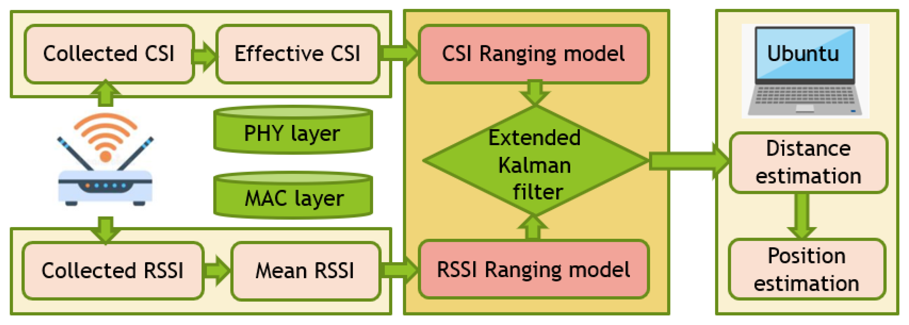
  • A cross-layer approach including MAC layer and physical layer that enable fine-grained indoor ranging in WLANs. Our proposed method includes two parts, RSSI-based ranging model and CSI-based ranging model.
  • Indoor ranging research based on RSSI and CSI in the environment of high-load Access Point (AP). This paper demonstrates the feasibility of this method in a high-load AP environment.
  • The method we propose is also the first one that uses extend Kalman filtering to combine RSSI-based signal attenuation model and CSI-based ranging model to perform distance estimation.
  • The experimental evaluation in two representative indoor environments to confirm the feasibility of our design and its effect on the ranging results. The experimental results show that the proposed algorithm outperforms existing algorithms.
The rest of this paper is organized as follows: Section 2 gives a preliminary of the basics of RSSI, CSI and EKF. In Section 3, the proposed method is described in detail; We use extended Kalman filter to estimate the distance through the nonlinear relationship between CSI, RSSI and distance. The experimental experiment and result are detailed in Section 4. Finally, conclusions and the future research are presented in Section 5.

2. Related Work

2.1. Characteristics of RSSI and CSI

The low-dimensional RSS information makes it possible to perform the regional level of indoor positioning. RSSI, as an easy to get a signal feature, is often used in an indoor positioning system. RSSI belongs to the Medium Access Control (MAC) layer and comes from each packet. Unlike RSS information, CSI information [17,18,19,20] considers the signal transmission between different subchannels and different antennas. In addition, its dimension and complexity provide information much richer than the RSS information.
This unique physical feature meets the following requirements:
(1)
It has excellent resistance to interference in the 2.4 GHz band signal and has less fluctuation in a stable environment. It can also reflect the changes in the environment.
(2)
The use of OFDM technology to distinguish signals of different paths as finely as possible.
CSI is a fine-grained attribute value of the physical layer that describes the amplitude and phase of the frequency domain corresponding to each subcarrier. The CSI can reflect the attenuation of the wireless signal as it travels between the transmitter and receiver. Table 1 demonstrates the differences between RSSI and CSI.
In this paper, the RSSI value and CSI value were collected at fixed positions of 1 m, 4 m and 7 m in the same indoor environment, and the results of their multipath effects were compared. Figure 2 compares the stability between the sampled RSSI value and the amplitude of the CSI sampled on channel 2.
Although the CSI value collected on a certain channel will change, compared with the collected RSSI value, the CSI value collected less varies in time and remains stable.

2.2. RSSI-Based Signal Attenuation Model for Indoor Ranging

Ranging information between two points is calculated using the received signal strength information. In free space, RSSI is inversely proportional to the square of the distance d between the receiving point and the transmitting point. Their relationship [21,22,23,24] can be expressed using the famous Friis formula:
P r d = P t G t G r λ 2 4 π 2 d 2 L
In Equation (1), P r ( d ) is the received power, and its unit is watts. P t is the transmit power in watts. G t is the transmit antenna gain. G r is the gain of the receiving antenna. λ is the wavelength of the transmitted signal; its unit is meter. L is a loss parameter which is irrelevant to the propagation environment. The system loss parameters represent the total loss of the actual system hardware. It includes transmission lines, filters, and antennas.
In general, L is greater than one. However, if we assume that the system hardware has no loss, we can let L = 1 . From Equation (1), we can observe that the attenuation of the received power is exponential with the distance. So, the free-space path loss can be directly derived from Equation (1) without any system loss.
P L F d [ d B ] = 10 log ( P t P r ) = 10 l o g ( G t G r λ 2 ( 4 π ) 2 d 2 )
We can ignore the antenna gain and let G t = G r = 1 . In a free-space model, the average received signal is in a logarithmic relationship with the distance d between the transmitter and receiver in all environments. Basically, a more general path loss model can be constructed using the environment-dependent signal attenuation factor to change the free-space path loss model. The mathematical expression of the signal attenuation log model is as follows:
R S S I = A 10 n log ( d d 0 ) + X 0 ,
where, RSSI indicates the received signal strength indication value in dBm. A is the signal strength at 1m from the source. d represents the distance between the transmitting node and the receiving node in meters. d 0 is the unit distance and usually takes 1 m. X ( 0 ) is a Gaussian random number taking a mean of 0 and its standard deviation range between 4 and 10. When the n value is smaller, the signal attenuation in the transmission process is smaller, and the signal can spread farther away. The range is generally between 2 and 4.

2.3. CSI-Based Signal Attenuation Model for Indoor Ranging

OFDM systems can modulate signals into multiple subcarriers and transmit them simultaneously in 802.11 a/g/n networks [25,26,27]. The CSI information obtained from the physical layer can reflect the channel quality between the transmitter and receiver. The CSI describes that signals are affected by multiple paths during propagation. Therefore, the channel can be estimated by CSI [28] analyzing the channel characteristics of the communication link. Table 2 shows the available information about CSI.
In an OFDM system, the received signal in the indoor environment can be expressed by Equation (4):
Y = H X + N
where Y is the received signal vector. H is the channel matrix. X is the transmitted signal vector. H is the channel matrix, and N is the additive Gaussian white noise.
The estimated CSI of all subcarriers is:
H ^ = Y X
where H ^ represents the channel frequency response (CFR) in the frequency domain. A set of CSI values can be obtained from the received packets, which can be expressed by Equation (6):
H = [ H 1 , H 2 , H 3 , , H k , , H n ] ,
where H k is the k-th subcarrier of CSI.
By modifying the wireless network card, CFR samples with 30 subcarriers ( n = 30 ) can be obtained by the Wi-Fi devices. Each group of CSI includes the amplitude and phase of subcarriers, as shown in Equation (7):
H k = H k e j H k
where H k represents the amplitude. H k represents the phase of k-th subcarriers.
An Intel 5300 wireless network card operating in a 20 MHz high-throughput mode (HT mode) under a MIMO system has p transmitting antennas and q receiving antennas. CSI can be expressed as a matrix of pxq dimension, as follows:
H ( f x ) = h 11 h 22 h 1 q h 21 h 22 h 2 q h p 1 h p 2 h p q
where H p q is a complex number, which contains the amplitude and phase of the subcarrier on each antenna.
Figure 3 and Figure 4 show the amplitude–frequency response and phase–frequency response of CFR under three receiving antennas. Analysis of Figure 4 shows that the phase information measured at the receiver is chaotic and we can not use it directly.
Currently, WLAN protocols, especially 802.11n, use OFDM and MIMO as their standard technologies. The MIMO technology enables the diversity transmission and reception of signals. These two technologies play an important role in the formation of CSI data. FILA [8] utilizes effective CSI to propose an indoor ranging algorithm. The CSI-based ranging formula is as follows:
C S I e f f = 1 K k f k f c × | | A | | k
where C S I e f f represents the effective CSI. K is the number of subcarriers. f c represents the calculated center frequency, and | | A | | k represents the amplitude of the filtered CSI on the k t h subcarrier. The propagation distance between the transmitter and receiver can be represented by effective CSI as follows:
d = 1 4 π [ ( c f c × | C S I e f f | ) 2 σ ] 1 n
where d represents the distance between the transmitter and the receiver, c is the radio velocity, f c is the central frequency of CSI, n is the path loss attenuation factor, and σ is the environmental factor.
The basic process is to collect the original CSI (CFR form existence) value of the ranging node at each reference node. According to the characteristics of the signal attenuation model, the specific relationship between CSI value and distance is obtained, and the mathematical model of CSI value and distance is established. Since CSI ranging is easily affected by the indoor environment, the indoor attenuation model based on the original CSI can not meet the requirements of the target object for ranging accuracy. At the same time, the mathematical model of CSI value and distance is not a linear equation. The function relationship between CSI and d can be obtained from Equation (11).
C S I e f f = c f c σ ( 4 π d ) n .

2.4. The Extended Kalman Filtering Algorithm

The Kalman Filter (KF) is an optimal sequential state estimation algorithm for a linear state-space model in terms of the mean squared estimation error. When the state-space model is nonlinear, the KF is no longer applicable and nonlinear filters, especially the Extended Kalman Filter (EKF) [14,15,16], become necessary. For the EKF, the nonlinear Gaussian state-space model is linearized around the current best estimates of states and the KF algorithm is applied to the linearized models. The EKF algorithm is divided into two parts: time and observation updates. In the time update, the state estimation is predicted by the system model; for the observation update, the predicted state estimate is corrected using the observation based on the observation model. This corrected state estimation is called the filtered state estimate and it is then used for the next time update.
The nonlinear state-space model can be described as:
X ( k ) = f [ X ( k 1 ) ] + G V ( k ) , V ( k ) N ( 0 , Q k ) Z ( k ) = h [ X ( k ) ] + W ( k ) , W ( k ) N ( 0 , R k )
Here, k = 1 , 2 , and X ( k ) and Z ( k ) are N and L dimensional random vectors called the state and the observation at k. V ( k ) and W ( k ) are independent zero-mean white Gaussian noises which covariance matrices are Q ( k ) and R ( k ) , respectively. These noises are also assumed as independent from X ( 0 ) . G is the noise input matrix.
The predicted state estimate and the covariance matrix are:
X ^ ( k | k 1 ) = f [ X ^ ( k 1 ) ]
P ( k | k 1 ) = A ( k 1 ) P ( k 1 | k 1 ) A ( k 1 ) T + G Q k G T .
The filtered state estimate and the covariance matrix are:
K ( k ) = P ( k | k 1 ) H ( k ) T H ( k ) P ( k | k 1 ) H ( k ) T + R ( k )
X ^ ( k ) = X ^ ( k | k 1 ) + K ( k ) [ Z ( k ) h [ X ^ ( k | k 1 ) ] ]
P ( k ) = [ I K ( k ) H ( k ) ] P ( k | k 1 )
Among them, A ( k 1 ) and H ( k ) are Jacobian matrices of non-linear systems, which are derived from partial derivatives of f [ X ( k 1 ) ] and h [ X ( k ) ] , respectively.

3. Indoor Localization Architecture and Methodology

In view of the disadvantages of traditional indoor positioning methods based on RSSI information or CSI information alone, we propose a novel positioning algorithm based on RSSI and CSI to make up for their shortcomings. This section focuses on the realization of the indoor ranging model. First, the structure of the model is introduced in its entirety. Then, the filtering fusion process of the extended Kalman filter is described in detail.

3.1. Indoor Localization Architecture

The basic flow of the algorithm starts from sending a ping command to the IP address of the AP at the receiving end to collect data packets. After collecting the data packets, the algorithm imports the data into MATLAB for processing and obtains the original RSSI value and original CSI value on each antenna of the MIMO system. The original RSSI value is averaged and the obtained CSI matrix is averaged with weights to obtain the effective CSI value. After that, the EKF is used to fuse the nonlinear RSSI ranging model and the nonlinear CSI ranging model to obtain the distance between the receiver and the transmitter. When using RSSI and CSI values to measure the access point or mobile terminal, the ranging model Equations (3) and (11) are usually used. The unknown parameters in the formula usually need to be trained to obtain. For different environments, the parameters will be different. In order to eliminate the influence of parameter changes on the ranking results, the propagation model formula is linearized. The architecture of the ranging algorithm is shown in Figure 5.

3.2. The Extended Kalman Filtering Algorithm Model

This paper uses the EKF filtering [29,30] function to filter the obtained RSSI average value and effective CSI value, and then combines the distance-related mathematical ranging model to reduce the impact of noise on the system and improve the ranging accuracy. The observation equation comes from the RSSI-based ranging model and effective CSI-based ranging model, which is shown as follows.
h [ X ( k ) ] = R S S I a n t e n n a 1 10 σ 1 l o g 10 ( d i s t ( X k , X r e f 1 ) / d 0 ) R S S I a n t e n n a L 10 σ L l o g 10 ( d i s t ( X k , X r e f L ) / d 0 ) C S I e f f a n t e n n a 1 c f c σ ( 4 π d i s t ( X ( k ) , X ( r e f 1 ) ) ) n C S I e f f a n t e n n a L c f c σ ( 4 π d i s t ( X ( k ) , X ( r e f L ) ) ) n
where d is the distance between the transmitter and receiver in indoor environments. R S S I a n t e n n a L and C S I e f f a n t e n n a L represent the RSSI value and the effective CSI at a distance d 0 = 1 m from the receiver reference point, respectively. L = p * q , where p and q represent the number of antennas at the transmitting node and the receiving node respectively. c is the radio velocity, f c is the central frequency of CSI. n is the path loss attenuation factor, and σ is the environmental factor, and d i s t ( ) is the Euclidean distance function.
We can calculate the Jacobian matrix of the observation function:
H ( k ) = 10 d i s t ( X k , X r e f 1 ) 10 d i s t ( X k , X r e f L ) 2 π c n σ f c ( 4 π d i s t ( X ( k ) , X ( r e f 1 ) ) ) n 2 1 2 π c n σ f c ( 4 π d i s t ( X ( k ) , X ( r e f L ) ) ) n 2 1
The covariance matrix of the observation noise is:
R k = R 11 0 0 0 R 22 0 0 0 0 R 2 L 2 L
The R k value is affected by the indoor environment. When the indoor environment is more complicated, the value is larger. Since the system model is linear, A ( k ) = I and G = I .

4. Experimental Environment and Results

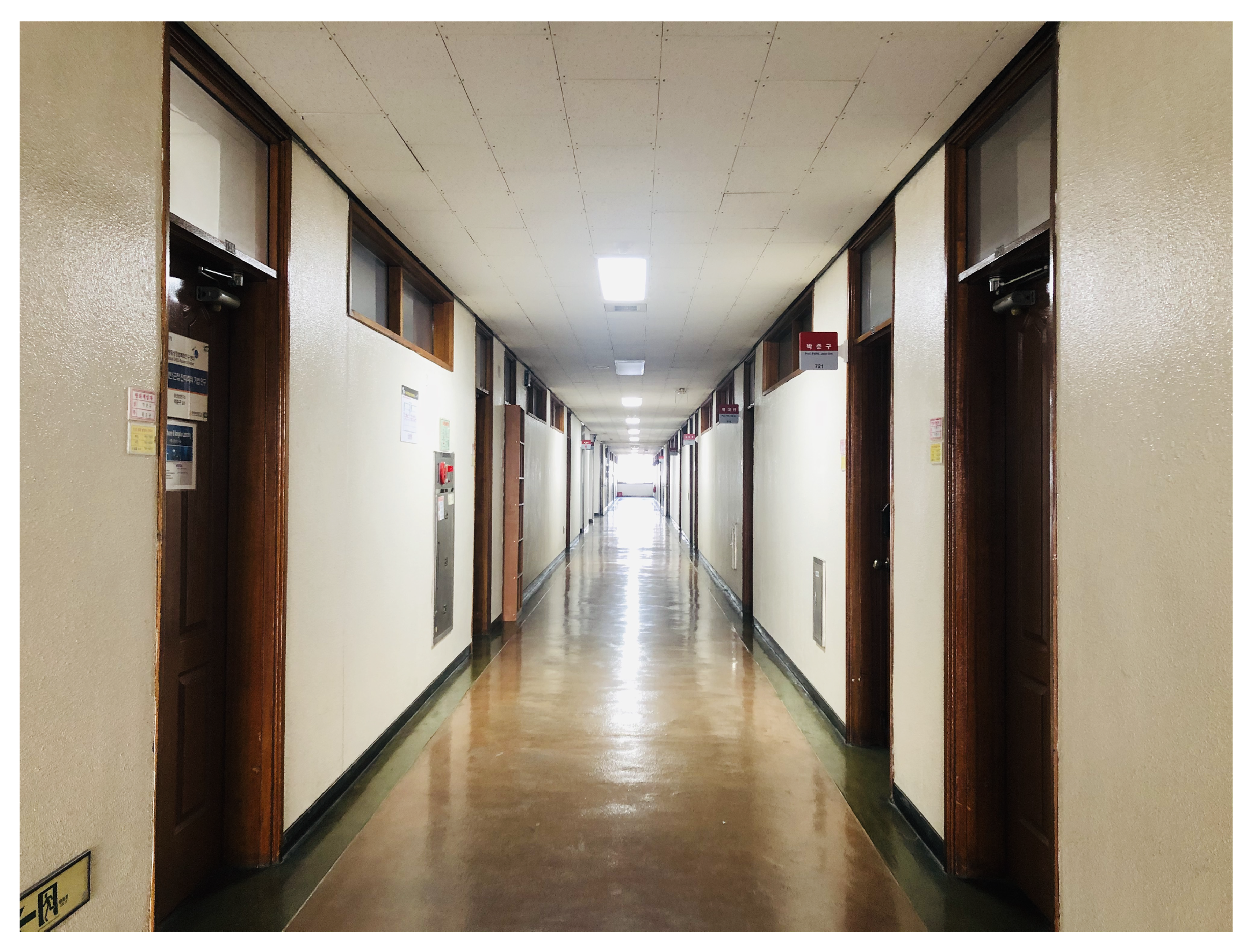
4.1. Experimental Environment

This experiment was conducted at the corridor on the 3rd floor of the IT-1 building and the hall on the 2nd floor of the IT-1 building at Kyungpook National University (KNU) as shown in Figure 6 and Figure 7. Figure 8 shows the schematic diagram of the experimental environment of the IT-1 building, which is a 2.5 m by 10 m corridor environment. Figure 9 shows the schematic diagram of the experimental environment of the IT-2 building, which is an 8 m by 10 m hall environment. In the collection of sample data, there are 10 reference points between AP and reference point (RP), each of which collects 1000 samples, and the interval between each reference point is 1 m.
In this paper, we use a laptop with a modified wireless network card and CSI tools [31,32] to obtain CSI data. The equipment required was: (1) a laptop with Intel 5300 for which the Ubuntu 14.04 operating system is installed with the customized kernel and wireless card drivers; (2) wireless AP based on 802.11n. We connect to the laptop through the Wi-Fi hotspot provided by the wireless AP. Since the 5GHz wireless signal has a strong ability to penetrate the wall, 5GHz was selected as the experimental frequency band. Currently, the commercial wireless network card supporting the IEEE 802.11n standard can provide the amplitude and phase difference information of different subcarriers in the form of the CSI matrix. The OFDM system of the IEEE 802.11n standard contains 56 subcarriers.
In this paper, the modified device can extract 30 subcarriers. Therefore, CSI is a numerical matrix of 3 × 3 × 30. Figure 3 shows that the antenna c did not work as expected. Thus, we use a 2 × 3 × 30 CSI numerical matrix for ranging. The collected CSI subcarrier information is an imaginary number that contains the amplitude and phase values of the subcarriers between different channels. Analysis of Figure 4 shows that the phase information measured at the receiving end is chaotic. There is no way to use it directly.

4.2. Experimental Results

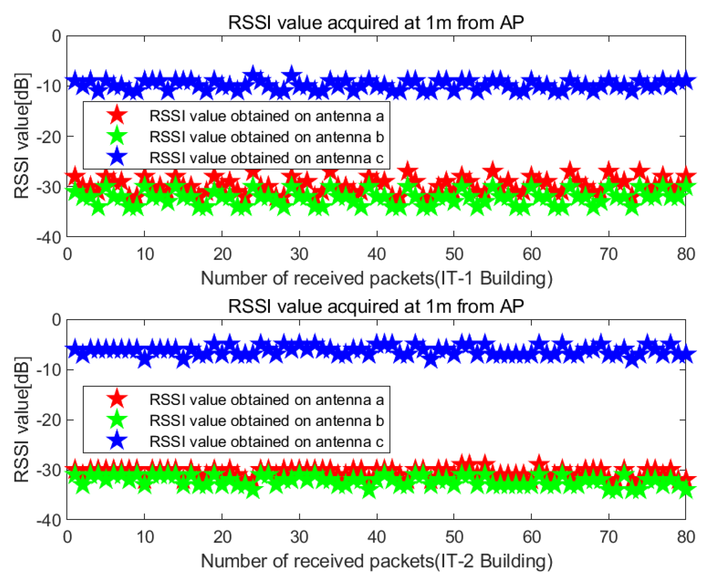
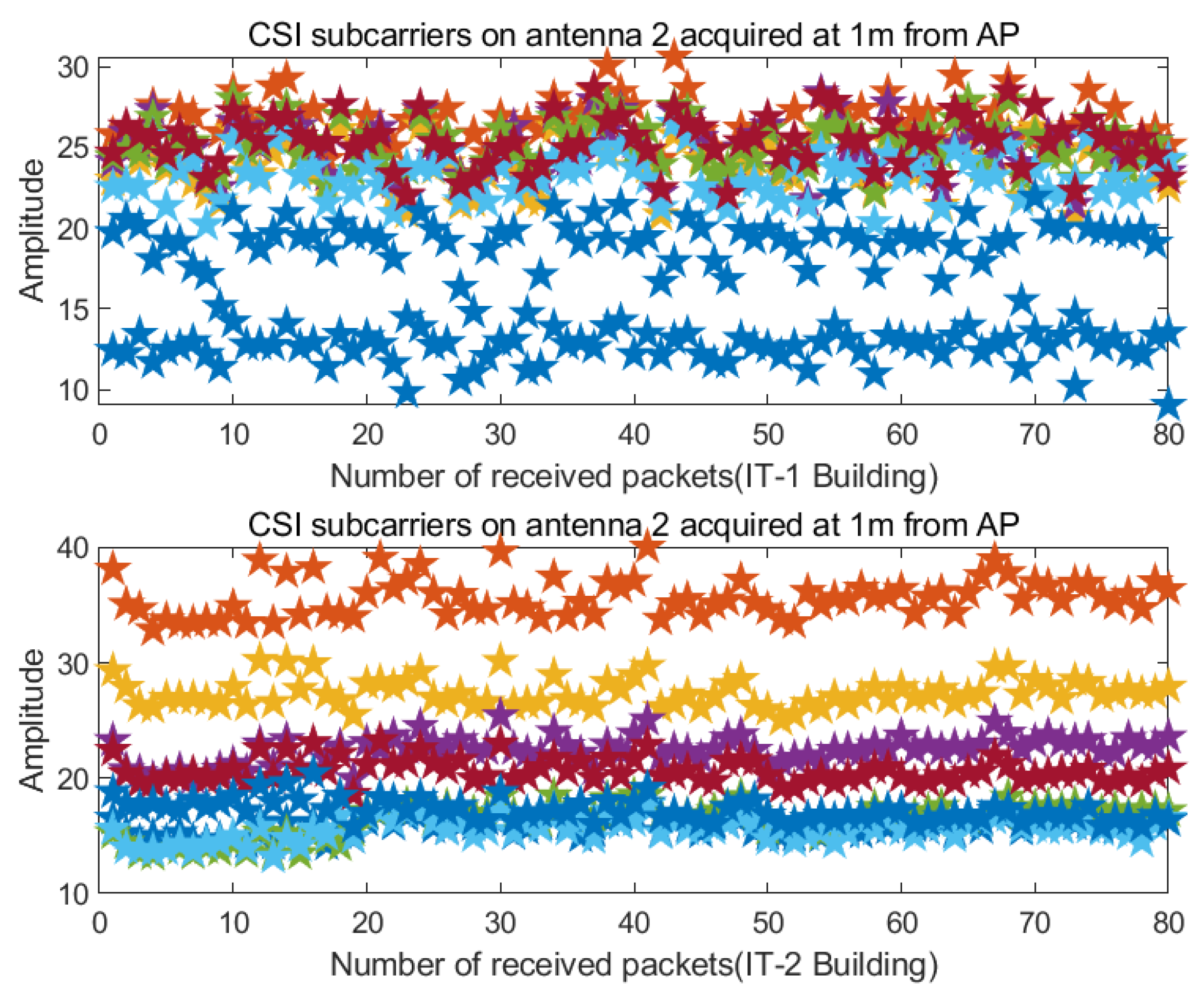
4.2.1. Data Collection and Processing of RSSI and CSI

The data collection and processing module include the collection and processing of RSSI and CSI. In this paper, the transmitter AP was IPtime N3004 which had three transmitting antennas. In this paper, the transmit frequency of IPtime N3004 is 5 GHz. The receiver was a Dell Inspiron n4010 laptop. Each pair of transmitting and receiving antennas can obtain the RSSI value and CSI of 30 subcarriers. For each packet, the RSSI value on different antennas and CSI data matrix of 270-dimension can be obtained. The third antenna did not work normally and therefore we chose 180 (2 × 3 × 30) dimensional CSI data matrix for experiments. Figure 10 shows the changes in the RSSI values obtained on different antennas in two different indoor environments. Figure 11 shows the variation of the subcarrier values of CSI on antenna 2 in two different indoor environments.
According to Equation (9), we process the acquired subcarriers to obtain an effective CSI value, as shown in the Figure 12.

4.2.2. Three-Dimensional Diagram of Nonlinear Ranging Model

The experiment was conducted in IT-1 building and IT-2 building of Kyungpook National University. Select the area covered by the Wi-Fi signal, select 10 test points in this area, and evenly distribute each test point for 100 times and 10 tests. Every reference point can get a total of 100,000 data values. We obtained the RSSI value and CSI value through MATLAB extraction and analysis. In the actual signal propagation environment, the RSSI value is susceptible to environmental influences. If the measured RSSI value is simply converted into a distance, the ranging error becomes larger. Therefore, when measuring distance, we should pre-process the RSSI value. We use the measured RSSI value multiple times to perform arithmetic average to improve the accuracy of the RSSI value. While CSI is relatively stable, we obtain the effective value of the CSI value by weighting the subcarriers.
The acquisition process of the ranging model can be divided into three stages; First, the RSSI and CSI of the transmitted signal of the transmitting node are obtained. Next, the receiving node uses the strength value of the received signal and the effective value of CSI to calculate the propagation loss of the ranging model and the parameters related to the indoor environment. Finally, the receiving node uses theoretical or empirical models to convert the signal propagation loss into the distance. The empirical model is a model formed by setting multiple reference points in the actual environment, and then measuring the relationship between signal strength and distance while at the same time combined with a mathematical fitting algorithm. The theoretical model selected in this paper is shown in Equations (3) and (11). Figure 13 shows the 3D graph of RSSI signal attenuation with distance in IT-1 building. Figure 14 shows the 3D graph of CSI effective value attenuation with distance in IT-1 building.
In practical applications, the complex and changeable indoor environment can cause multipath noise in RSSI and CSI measurements. It is assumed that this noise is additive white noise, which conforms to the Gaussian distribution. We need to choose the most suitable filter to eliminate the influence of noise on RSSI and CSI values, and obtain accurate distance measurement results.

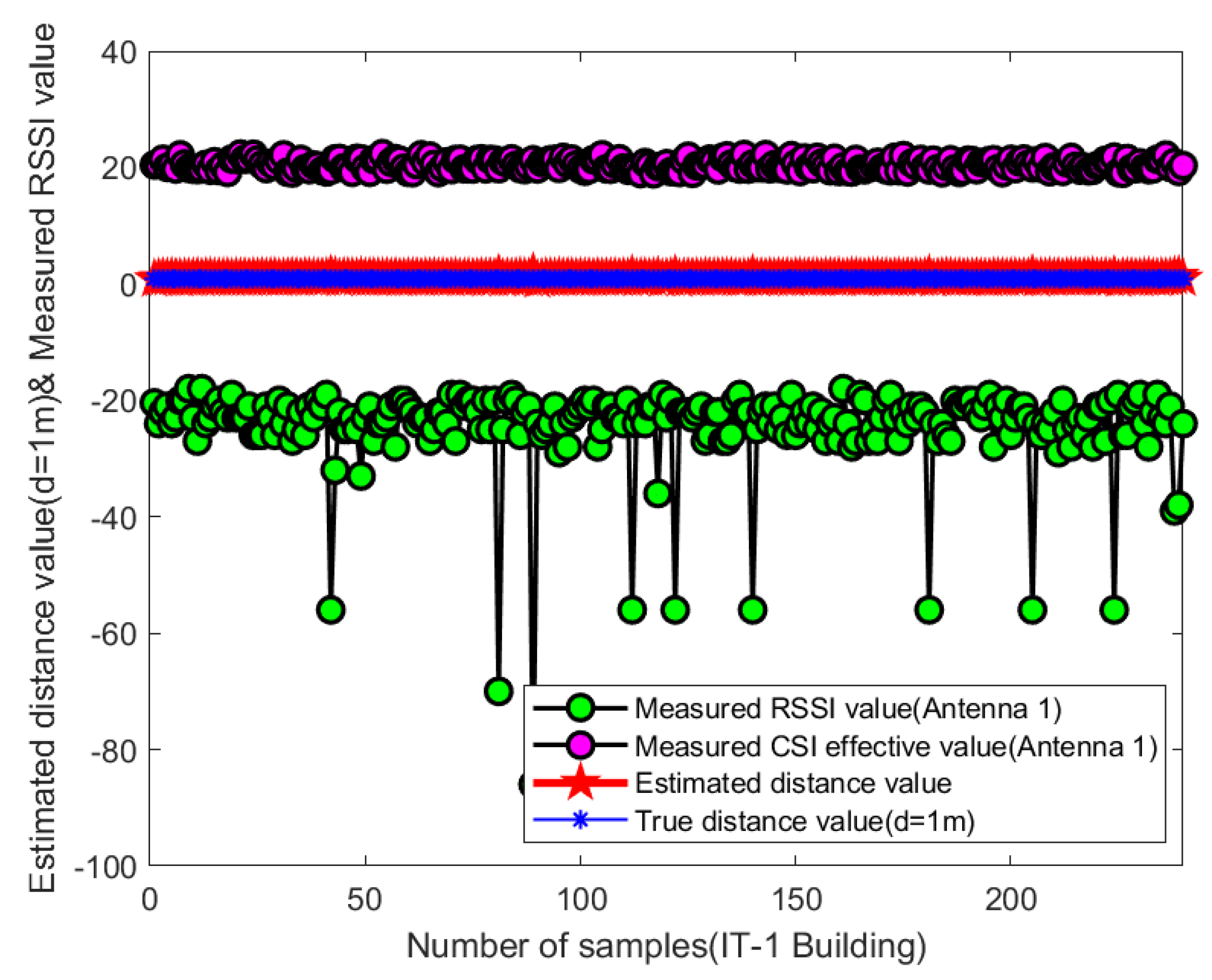
4.2.3. Distance Estimation Based on Extended Kalman Filtering

EKF has important theoretical significance and broad application prospects for the state estimation of nonlinear systems. Using the Extended Kalman Filter (EKF) method, a linearized standard Kalman filter model of the system can be established. The EKF algorithm has a simple structure and a certain accuracy, so it is widely used.
At each reference point, the EKF is used to filter the obtained RSSI value and CSI effective value. The processing procedure (the reference point distance is 1 meter) is shown in Figure 15. Figure 15 shows the comparison of the distance value and the real value after the extended Kalman filter.
To analyze the improvement of the distance estimation accuracy of the proposed method more intuitively and clearly, we compare the obtained estimated distance with the real distance. Figure 16 shows the accuracy of the proposed algorithm for distance estimation. We used the proposed algorithm to filter all reference points within 10m in two indoor environments. We use MATLAB to plot the estimated distance error. Figure 17 shows a comparison of estimated distance error values between 1 m and 10 m.

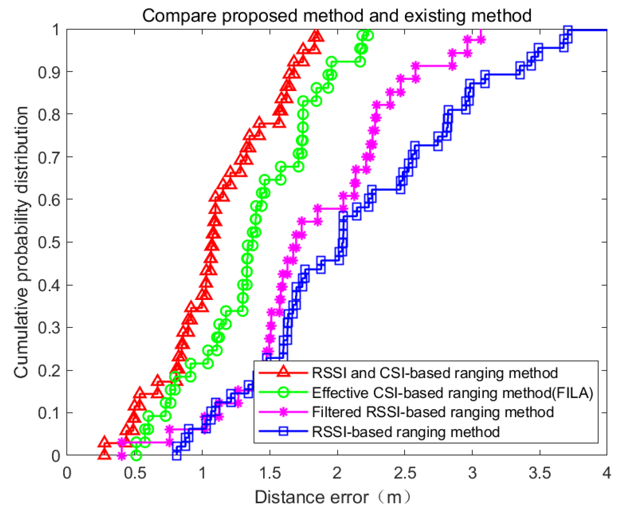
4.2.4. Performance Evaluation

We evaluate the performance of our proposed ranging method under the two representative indoor environments. Figure 18 presents the Cumulative Distribution Function (CDF) of distance errors with the four ranging methods in the corridor experiment. In the IT-1 building experiment, the mean distance error is about 1.049 m and a standard deviation of 0.623 m for our proposed ranging method. In Figure 19, we plot the CDF of distance errors with the four ranging methods in the IT-2 building of KNU. In this propagation environment, our proposed method can achieve a 1.5 m distance error for over 70% of the reference points. The algorithm we proposed can obtain the best ranging results, and is the most accurate of the four ranging methods.
Figure 18 and Figure 19 shows our proposed ranging method outperforms the existing ranging methods in both scenarios. The RSSI-based ranging method and the CSI-based ranging methods do not perform as well as our RSSI and CSI-based scheme. In the IT-1 building environment, the RSSI-based ranging method only manages to achieve 25% of the points that have an error under 1.5 m. The filtered RSSI-based ranging method only manages to achieve 36% of the points that have an error under 1.5 m. This is in contrast to that of the CSI-based ranging method which achieves 67% of the points that have an error under 1.5 m. These same methods achieved 30%, 37% and 60% of the points that have an error under 1.5 m in IT-2 building environment respectively.
We evaluate the performance of the proposed ranging algorithm based on RSSI and CSI using EKF through the statistical results of two indoor environments. Table 3 and Table 4 list the average and standard deviation of the ranging error, respectively. Unlike FILA, the proposed algorithm utilizes RSSI and various CSI subcarriers acquired on each antenna. The algorithm can achieve higher accuracy. Two ranging methods using CSI (i.e., the proposed method and FILA) are superior to the two ranging methods based on RSSI.
Different from the RSSI, the filtered RSSI and the CSI-based ranging methods, our RSSI and CSI-based ranging method using EKF suppresses rich multipath effects in an indoor environment. It also achieves significantly higher accuracy. This result indicates that our proposed method is able to effectively estimate and compensate for the ranging result.

5. Conclusions and Future Work

The main contributions of this article are as follows: First, a novel ranging scheme based on CSI and RSSI using EKF is proposed. Second, an indoor ranging algorithm based on RSSI and CSI in the environment of high-load AP is proposed, which solves the ranging accuracy problem under high load AP. This paper demonstrates the feasibility of this method in a high-load AP environment and proves the accuracy of the algorithm through related experiments. We also compared it with several other related algorithms. Third, we use the DELL Inspiron n4010 laptop and commercial 802.11n wireless network card driver to build the experimental environment. Compared with existing other ranging methods, the proposed method does not require additional equipment and can be applied to a wider range of indoor situations. The experimental results show that the proposed ranging method effectively improves the accuracy of the indoor environment. Of course, the current system is still insufficient and we need to continue improving it in our future work. We could consider the participation of multiple APs in the experiment. Additionally, as the indoor environments are complex and vary with time due to people, we will analyze impacts brought about by these factors.

Author Contributions

J.W. proposed the idea and implementation methodology, performed all experiments and wrote the paper, verified the experiment process and results; J.G.P. reviewed and edited paper, and supervised the work. All authors have read and agreed to the published version of the manuscript.

Funding

This study is supported by the BK21 Plus project funded by the Ministry of Education, Korea (21A20131600011). This study is supported by Smart City R&D project of the Korea Agency for Infrastructure Technology Advancement (KAIA) grant funded by the Ministry of Land, Infrastructure and Transport (Grant 18NSPS-B149843-01).

Conflicts of Interest

The authors declare no conflict of interest.

References

  1. Rycroft, M.J. Understanding GPS. Principles and applications. Second Edition. J. Atmos. Sol.-Terr. Phys. 1997, 59, 598–599. [Google Scholar] [CrossRef]
  2. El-rabbany, A. Introduction to GPS: The Global Position System; Artech House: New York, NY, USA, 2006. [Google Scholar]
  3. Crow, B.P.; Widjaja, I.; Kim, J.G.; Sakai, P.T. IEEE 802.11 wireless local area networks. IEEE Commun. Mag. 1997, 35, 116–126. [Google Scholar] [CrossRef]
  4. Chen, H.X.; Hu, B.J.; Zheng, L.L.; Wei, Z.H. An Accurate AoA Estimation Approach for Indoor Localization Using Commodity Wi-Fi Devices. In Proceedings of the 2018 IEEE International Conference on Signal Processing, Communications and Computing (ICSPCC 2018), Qingdao, China, 14–17 September 2018. [Google Scholar]
  5. Güvenç, I.; Chong, C.C. A survey on TOA based wireless localization and NLOS mitigation techniques. IEEE Commun. Surv. Tutor. 2009, 11, 107–124. [Google Scholar] [CrossRef]
  6. Makki, A.; Siddig, A.; Saad, M.; Cavallaro, J.R.; Bleakley, C.J. Indoor Localization Using 802.11 Time Differences of Arrival. IEEE Trans. Instrum. Meas. 2016, 65, 614–623. [Google Scholar] [CrossRef]
  7. Xu, J.; Liu, W.; Lang, F.; Zhang, Y.; Wang, C. Distance Measurement Model Based on RSSI in WSN. Wirel. Sens. Netw. 2010, 2, 606. [Google Scholar]
  8. Wu, K.; Xiao, J.; Yi, Y.; Gao, M.; Ni, L.M. FILA: Fine-grained indoor localization. In Proceedings of the IEEE INFOCOM, Orlando, FL, USA, 25–30 March 2012. [Google Scholar]
  9. Wang, K.; Yu, X.; Xiong, Q.; Zhu, Q.; Lu, W.; Huang, Y.; Zhao, L. Learning to improve WLAN indoor positioning accuracy based on DBSCAN-KRF Algorithm from RSS Fingerprint Data. IEEE Access 2019, 7, 72308–72315. [Google Scholar] [CrossRef]
  10. Xie, C.; Guan, W.; Wu, Y.; Fang, L.; Cai, Y. The LED-ID Detection and Recognition Method Based on Visible Light Positioning Using Proximity Method. IEEE Photonics J. 2018, 10, 1–16. [Google Scholar] [CrossRef]
  11. Destiarti, A.R.; Kristalina, P.; Sudarsono, A. Mobile cooperative tracking with RSSI ranging in EKF algorithm for indoor wireless sensor network. In Proceedings of the 2016 International Conference on Knowledge Creation and Intelligent Computing (KCIC 2016), Manado, Indonesia, 15–17 November 2016. [Google Scholar]
  12. Xiao, J.; Wu, K.; Yi, Y.; Ni, L.M. FIFS: Fine-grained indoor fingerprinting system. In Proceedings of the 2012 21st International Conference on Computer Communications and Networks (ICCCN 2012), Munich, Germany, 30 July–2 August 2012. [Google Scholar]
  13. Wang, X.; Gao, L.; Mao, S.; Pandey, S. DeepFi: Deep learning for indoor fingerprinting using channel state information. In Proceedings of the 2015 IEEE Wireless Communications and Networking Conference (WCNC 2015), New Orleans, LA, USA, 9–12 March 2015. [Google Scholar]
  14. Chapre, Y.; Ignjatovic, A.; Seneviratne, A.; Jha, S. CSI-MIMO: Indoor Wi-Fi fingerprinting system. In Proceedings of the Conference on Local Computer Networks (LCN), Edmonton, AB, Canada, 8–11 September 2014. [Google Scholar]
  15. Hsieh, C.H.; Chen, J.Y.; Nien, B.H. Deep Learning-Based Indoor Localization Using Received Signal Strength and Channel State Information. IEEE Access 2019, 7, 33256–33267. [Google Scholar] [CrossRef]
  16. Simon, D. Kalman filtering with state constraints: A survey of linear and nonlinear algorithms. IET Control Theory Appl. 2010, 4, 1303–1318. [Google Scholar] [CrossRef] [Green Version]
  17. Zhang, H.; Du, H.; Ye, Q.; Liu, C. Utilizing CSI and RSSI to Achieve High-Precision Outdoor Positioning: A Deep Learning Approach. In Proceedings of the IEEE International Conference on Communications, Shanghai, China, 20–24 May 2019. [Google Scholar]
  18. Zhang, L.; Ding, E.; Hu, Y.; Liu, Y. A novel CSI-based fingerprinting for localization with a single AP. EURASIP J. Wirel. Commun. Netw. 2019, 2019, 51. [Google Scholar] [CrossRef]
  19. Yang, Z.; Zhou, Z.; Liu, Y. From RSSI to CSI: Indoor localization via channel response. ACM Comput. Surv. 2013, 46, 1–32. [Google Scholar]
  20. Wang, X.; Gao, L.; Mao, S.; Pandey, S. CSI-Based Fingerprinting for Indoor Localization: A Deep Learning Approach. IEEE Trans. Veh. Technol. 2017, 66, 763–776. [Google Scholar] [CrossRef] [Green Version]
  21. Zhu, X.; Feng, Y. RSSI-based Algorithm for Indoor Localization. Commun. Netw. 2013, 5, 37. [Google Scholar] [CrossRef]
  22. Pathak, O.; Palaskar, P.; Palkar, R.; Tawari, M. Wi-Fi Indoor Positioning System Based on RSSI Measurements from Wi-Fi Access Points—A Tri-lateration Approach. Int. J. Sci. Eng. Res. 2014, 5, 1234–1238. [Google Scholar]
  23. Li, G.; Geng, E.; Ye, Z.; Xu, Y.; Lin, J.; Pang, Y. Indoor positioning algorithm based on the improved rssi distance model. Sensors 2018, 18, 2820. [Google Scholar] [CrossRef] [PubMed] [Green Version]
  24. Zanca, G.; Zorzi, F.; Zanella, A.; Zorzi, M. Experimental comparison of RSSI-based localization algorithms for indoor wireless sensor networks. In Proceedings of the Workshop on Real-World Wireless Sensor Networks (REALWSN 2008); ACM: Glasgow, Scotland, 2008. [Google Scholar]
  25. Adachi, T. IEEE802.11n. Kyokai Joho Imeji Zasshi/J. Inst. Image Inf. Telev. Eng. 2011, 65, 950–953. [Google Scholar] [CrossRef]
  26. Letor, N.; Torfs, W.; Blondia, C. Multimedia multicast performance analysis for 802.11n network cards. In Proceedings of the IFIP Wireless Days, Dublin, Ireland, 21–23 November 2012. [Google Scholar]
  27. Lin, M.F.; Tzu, J.Y.; Lin, L.; Lee, H.M. The IEEE802.11n capability analysis model based on mobile networking architecture. In Proceedings of the IEEE International Conference on Systems, Man and Cybernetics, San Antonio, TX, USA, 11–14 October 2009. [Google Scholar]
  28. Wang, X.; Gao, L.; Mao, S. CSI Phase Fingerprinting for Indoor Localization with a Deep Learning Approach. IEEE Internet Things J. 2016, 3, 1113–1123. [Google Scholar]
  29. Lee, S.H.; Lim, I.K.; Lee, J.K. Method for Improving Indoor Positioning Accuracy Using Extended Kalman Filter. Mob. Inf. Syst. 2016, 2016. [Google Scholar] [CrossRef] [Green Version]
  30. Ben Kilani, M.; Raymond, A.J.; Gagnon, F.; Gagnon, G.; Lavoie, P. RSSI-based indoor tracking using the extended Kalman filter and circularly polarized antennas. In Proceedings of the 2014 11th Workshop on Positioning, Navigation and Communication (WPNC 2014), Dresden, Germany, 12–13 March 2014. [Google Scholar]
  31. Halperin, D.; Hu, W.; Sheth, A.; Wetherall, D. Tool release: Gathering 802.11n traces with channel state information. Comput. Commun. Rev. 2011, 41, 53. [Google Scholar] [CrossRef]
  32. Liu, X.L.; Hu, W.; Pu, Q.; Wu, F.; Zhang, Y. ParCast: Soft video delivery in MIMO-OFDM WLANs. In Proceedings of the Annual International Conference on Mobile Computing and Networking (MOBICOM), Istanbul, Turkey, 22–26 August 2012. [Google Scholar]
Figure 1. The position estimation methods between range-based and range-free algorithms.
Applsci 10 03687 g001
Figure 2. Comparison of the stability between the sampled RSSI value and the amplitude of the CSI sampled on channel 2.
Applsci 10 03687 g002
Figure 3. The amplitude frequency response of channel frequency response (CFR) under three receiving antennas.
Applsci 10 03687 g003
Figure 4. The phase frequency response of CFR under three receiving antennas.
Applsci 10 03687 g004
Figure 5. Indoor localization architecture.
Applsci 10 03687 g005
Figure 6. Indoor experiment environment at the 3rd floor of IT-1 building.
Applsci 10 03687 g006
Figure 7. Indoor experiment environment at the 2rd floor of IT-2 building.
Applsci 10 03687 g007
Figure 8. Schematic diagram of the indoor experiment environment at the 3rd floor of IT-1 building.
Applsci 10 03687 g008
Figure 9. Schematic diagram of indoor experiment environment at the 2rd floor of IT-2 building.
Applsci 10 03687 g009
Figure 10. RSSI values obtained on different antennas in different indoor environments.
Applsci 10 03687 g010
Figure 11. CSI subcarrier values obtained on antenna 2 in different indoor environments.
Applsci 10 03687 g011
Figure 12. CSI effective values obtained on antenna 2 in different indoor environments.
Applsci 10 03687 g012
Figure 13. 3D graph of RSSI signal attenuation with distance in IT-1 building.
Applsci 10 03687 g013
Figure 14. 3D graph of CSI effective value attenuation with distance in IT-1 building.
Applsci 10 03687 g014
Figure 15. The accuracy of distance estimation (the proposed algorithm).
Applsci 10 03687 g015
Figure 16. The comparison of the distance value and the real value after the extended Kalman filter (EKF).
Applsci 10 03687 g016
Figure 17. The comparison of the estimated distance error value between 1 m and 10 m.
Applsci 10 03687 g017
Figure 18. CDF of distance errors with the four ranging algorithms in IT-1 building.
Applsci 10 03687 g018
Figure 19. Cumulative Distribution Function (CDF) of distance errors with the four ranging algorithms in IT-2 building.
Applsci 10 03687 g019
Table 1. The differences between Received Signal Strength Indicator (RSSI) and Channel State Information (CSI).
CategoryRSSICSI
Time resolutionPacketMultipath signal cluster
Frequency resolutionNoneSubcarrier
StabilityLowHigh
DimensionOne dimensionHigh dimension
UniversalityAll Wi-Fi devicesSome Wi-Fi devices
Table 2. Channel state information.
Data InformationProperties
Bfee-countNumber of Bfee count beamforming sent to user space by drive record
NrxNumber of Nrx receiving antennas (Intel5300 network card is usually 3)
NtxNumber of Ntx transmit antennas
rssi-a, rssi-b, rssi-cReceived signal strength of each receiving antenna
rateRate the transmission rate of each packet
noisenoise
CSICSI data itself is a three-dimensional arrays of Nrx * Ntx * 30
Table 3. Comparison of four indoor ranging algorithms (IT-1 building).
Indoor Ranging AlgorithmMean Ranging ErrorStandard Deviation
RSSI-based algorithm2.041 m1.214 m
Filtered RSSI-based algorithm1.696 m0.908 m
CSI-based algorithm (FILA)1.381 m0.577 m
RSSI and CSI-based algorithm (Proposed algorithm)1.049 m0.623 m
Table 4. Comparison of four indoor ranging algorithms (IT-2 building).
Indoor Ranging AlgorithmMean Ranging ErrorStandard Deviation
RSSI-based algorithm1.798 m1.279 m
Filtered RSSI-based algorithm1.669 m1.243 m
CSI-based algorithm (FILA)1.395 m0.972 m
RSSI and CSI-based algorithm (Proposed algorithm)1.103 m0.612 m

