1. Introduction
With the development of technologies such as 5G, big data, and cloud computing, large amounts of data need to be generated, sent, and stored every day [
1]. These data include sensitive personal finances, health information, and business and state secrets. Once the data is leaked, it will cause an unpredictable loss. In conventional encryption systems, data security relies on the cryptographic algorithms, public-key and symmetric, based on computational complexity.
However, the emergence of quantum computers will allow breaking currently used public-key cryptosystems and thereby put an end to the secure distribution of business secrets, banking information, health data, and so on, over the Internet.
Even though the current quantum-computing technology is immature, the data related to census, military technology, and other sensible information must be kept secret from the eavesdropper. The eavesdropper can wait for the arrival of the quantum computing by “saving at first and then decrypting”. QKD makes full use of the advantages of quantum mechanical signals’ no-cloning theorem and uncertainty principle, which makes it impossible for an eavesdropper to keep a transcript of quantum signals sent in a QKD process. Therefore, it is a promising method to distribute a cryptographic key, which can be used in conjunction with one-time pad (OTP) for absolutely secure communication theoretically, between a legal sender and a receiver without making assumptions on the computational power of a potential eavesdropper [
2,
3,
4,
5].
A separate point-to-point QKD link does not support some applications very well, and therefore, QKD network structures must be considered in order to enable access by a greater number of users and also to extend the reach and geographical coverage [
6]. However, point-to-point quantum-key-generation rate is limited by distance. Some schemes are designed to extend the distance of secure QKD [
7,
8]. Among them, the trusted-relay scheme is the easiest and most convenient, and has been used as a standard for existing QKD networks [
9,
10].
Some studies are carried out based on the trusted-relay QKD network. By constructing a quantum key pool (QKP) to allocate and manage quantum keys, the optimizations of survivability [
11], cost [
12,
13], and resource utilization [
14] in QKD networks have been realized. However, research on QKP management always focuses on how to use the keys that are relayed successfully, and rarely cares about the keys that are in the failed relay process. In terms of key recycling, some researches focus on the reuse of authentication keys in quantum channels [
15] and theoretically prove the security of the keys recycled [
16]. The QKR mechanism based on QKD is a classical protocol, and the existing classical-channel security [
17] and intrusion-detection technology [
18] cannot guarantee that the signals be immune to eavesdropping. However, quantum channels can theoretically detect all eavesdropping behaviors, which is very different from the classical channels. Therefore, the keys recycling in the classical channel cannot directly reuse all the recycled keys.
In this paper, we focus on how to manage, recycle, and securely reuse keys that are failed to be relayed under abnormal circumstances. The main contributions in this work are three-fold: (1) The idea of recycling the relay key is proposed, and a QKP communication mechanism based on QKD-over-optical-network architecture is proposed to synchronize algorithm information; (2) The types of keys that can be recycled are defined, the QKR mechanism and three specific implementation algorithms are proposed and the service-security-classification method is adopted to use different keys for different security needs of the service; and (3) The simulation shows that the QKD system with QKR is superior to the QKD system without QKR mechanism in terms of key-utilization rate and service-security coverage.
The rest of this paper is organized as follows.
Section 2 introduces some related technologies and the basis of the key-recycling mechanism.
Section 3 describes the problem.
Section 4 gives the basic settings and related notations. Three QKR mechanisms are proposed and described in
Section 5 and the performance evaluation and analysis for the QKR mechanisms are discussed in
Section 6.
Section 7 concludes this study.
2. QKD Networks with QKP
This section focuses on some key technologies that support QKD networks. First, a classic point-to-point QKD scheme is presented. Then, based on the objective to increase the key rate, an easy-to-implement QKD distance-extension scheme is introduced. Finally, the QKD-over-optical-network architecture is revealed, and the quantum-key-pool negotiation mechanism is proposed on the architecture.
2.1. Point-To-Point QKD System
The four-state protocol originally proposed by Bennett and Brassard in 1984, called BB84 [
19], is marked as the beginning of the development of QKD technology and most widely implemented in the world. As shown in
Figure 1, in the BB84 protocol, Z base is composed of |H> and |V> (Z = |H><H| +|V><V|) and X base is composed of |+> and |-> (X = |+><+| +|-><-|). Therefore, if the Z-base is used to measure |H> and |V>, a definitive result will be obtained, while the measures |+> and |-> will lead to uncertain results. Based on the above principles, the main part of BB84 protocol is described in the following three steps.
2.1.1. Modulate Bit to qbit
Alice selects two sets of binary random sequences and perform corresponding quantum state preparation according to the values of two sets of random numbers. One of the random sequence named raw keys determines the classical bits corresponding to the modulated quantum state as denoted by step (①) in
Figure 1. Another random sequence, called named base sequence, determines which base the modulated quantum state belongs to, such as 0 for the Z base and 1 for the X base (step②). For example, when the classical bit is 0, it is modulated to |H> or |->, and when the classical bit is 1, it is modulated to |V> or |+>. Alice transmits a prepared single photon sequence to Bob through the quantum channel (step ③).
2.1.2. Measuring qbit
Bob uses a single photon detector to receive quantum signals on the quantum channel and measures quantum polarization states independently. Bob generates a sequence of random numbers called named base sequence B, which determines the measurement base according to its value. Similar to the mechanism of base sequence A, when the value is 0, the X base is selected by Bob to measure the quantum state, and when the value is 1, the Z base is selected (step ④). After the measurement, Bob records the photon polarization state of each measurement and its corresponding bit information. When the measurement result is |H> or |->, the classic bit is 0, and when the measurement result is |V> or |+>, the classic bit is 1 (step ⑤). Due to the inevitable attenuation problem of the quantum channel and the detection deviation of the device, the number of quantum states received and measured by Bob may not necessarily equal to the number of quantum states sent by Alice. A clock channel is needed here to achieve the accurate synchronization of the qubit transmission and reception.
2.1.3. Matching Base
Alice and Bob match the bases in the public channel, then discard the corresponding bits when the code base and measurement are different (steps ⑥ and ⑦). On average, Alice and Bob will have about half the length of the original bit sequence, because the probability of Alice and Bob using a different polarization base is 1/2.
At this time, the random sequence shared by Alice and Bob is a rough quantum key (⑧), and after a series of post-processing steps, such as error estimation, error correction, and secret amplification, a sequence of secure keys are obtained.
2.2. Trusted Repeaters for Distance Extension
In 2002, Elliott et al. proposed the idea of using trusted nodes for quantum-key-distribution networking [
20]. On the basis of the point-to-point QKD system, the “one-time-pad” cryptographic algorithm is used to realize the key distribution of both parties in the long-distance communication through the “hop-by-hop” encryption method. At present, many quantum-key networks based on key relay have been built in countries around the world. In 2008, the European countries established the famous SECOQC (secure communication based on quantum cryptography) network. In 2010, Japan established a six-node QKD network in Tokyo. China has also established several quantum-key networks, and the world’s first wide-area quantum key network - "Beijing–Shanghai trunk line" also uses key-trusted repeaters to generate end-to-end keys.
The specific implementation process is shown in
Figure 2. Alice and Bob need to share the key K
A on the premise that the point-to-point key distribution is completed. First, key sequences K
A and K
B are shared by Alice-trusted relay pair and Bob-trusted relay pair, respectively (step ①). Then a bit-by-bit exclusive-or (XOR) with K
A and K
B is executed at the trusted relay node. The encrypted bit sequence is sent to Bob (step ②). Finally, Bob receives the bit sequence and decrypts it using K
B. K
A was shared by Alice and Bob successfully (step ③). Since the relay node also knows the K
A when relaying, the relay node is required to be trusted. Subsequently, schemes such as bit transmission, random routing, multipath transmission, and XOR storage are proposed to reduce or even eliminate the requirement for node credibility.
2.3. QKD Over Optical Network Architecture
The photonic network is an emerging infrastructure of optical communication similar to the IP-over-optical networks. According to the QKD key technology, QKD-over-optical network architecture is depicted in
Figure 3. According to the supply and demand relationship of the key, the whole architecture is logically divided into a key-supply part (blue area) and a key-consumption part (yellow area).
The key-supply part is divided into QKD plane and key management plane from bottom to up. The QKD plane consists of optical links and quantum nodes that integrates one or more sets of quantum transceivers, and the channel type is QCh. The point-to-point QKD protocols such as BB84, GG02, MDI runs on the plane to provide point-to-point quantum keys for the upper layer. In key management plane, the quantum key pool (QKP) acts as a node, and its physical implementation can be thought as a server that stores and manages keys deployed on the nodes. Nodes are fully connected through the logical channels which are based on classic data channels. The quantum key is stored in the QKP in the form of binary bits. The key-management plane provides end-to-end quantum keys for the upper layer by means of hop-by-hop relay routing. The PCh required by the QKD plane and key management plane in this architecture is provided by the data channel (DCh) of the key-consumption part.
The key-consumption part is divided into Optical network and IP network from bottom to up. The optical network is a WDM network and the nodes are facilitated with optical cross-connects (OXCs) with wavelength switching capabilities. In the IP network, the router is connected to the OXC directly, so the services can be dealt with all-optical processing. Therefore, if the quantum node is deployed on the OXC, the QKD network will provide the secure keys for both the IP network and the optical network [
21,
22].
3. Problem Statement
The relaying process of quantum keys can be implemented by transmitting information through a public data channel. As shown in
Figure 4, Alice and Bob need to share the keys by using the trusted relay, where the Alice-Repeater pair and the Repeater-Bob pair have shared the keys K
Ai and K
Bj (i, j∈N), respectively. Due to the differences in the relay-routing algorithm, the keys K
Ai and K
Bj may have separately experienced different numbers (the number may be 0) of trusted-relay nodes before sharing to the Repeater. According to the trusted-relay and the one-time-pad principle, in order to share one united end-to-end key, each node that is selected by the relay route will consume the same number of point-to-point keys. It is assumed that if the length of K
A1 is n and the Alice-Repeater pair needs to pass through two trusted relay nodes, sharing the K
A1 between the Alice-Repeater pair will require an additional 2n keys. K
A1 is generated by Alice and the first relay node for point-to-point QKD. The key-relay process consumes a large number of keys, and the number of keys consumed is positively correlated with the number of relay nodes.
If Alice and Bob want to share the key pair KA1, firstly KA1 XOR KB1 is executed at the trusted relay (step①) and then the XOR-ed result is sent to Bob. Packet loss and bit errors in actual operational IP networks may occur due to different factors like, rerouting, network congestion, cache processing, the device’s actual performance, network environment, and other factors. Packet loss (step ②) or bit error (step ②’) occurs while the key is being relayed, which may result in the key not being successfully shared. When the key KA1 is not successfully distributed, a redistribution process is performed. The key redistribution process is similar to the former process. Because the failure of the key-relay process may be caused by the eavesdropper’s activity or malicious attack. When the redistribution process occurs, in order to ensure the absolute security of the keys that need to be shared (to meet the condition that the key is used only once), the key pairs KA1 and KB1 that got successfully relayed before the current QKD, must be destroyed. The new key pairs KA2 and KB2 are used to re-relay (step ③④). The new key KA2 is shared between Alice and Bob. However, the practice of discarding the key pair KA1 and KB1 directly results in a great waste of the keys, not only the keys KA1 and KB1 are wasted, but also the relay keys used in the relay process are wasted. Further, the network key demand is increased, and the security requirements of the service are difficult to guarantee. Therefore, the idea of key recycling is proposed that collects and processes the keys that failed in similar scenarios discussed above, and reuses those keys to encrypt the services with low security level.
The probability and characteristics of packet loss and bit error are different in different network scenarios. The typical two scenarios are satellite networks and optical networks, representing networks with the characteristics of high packet loss rate (PLR) and low PLR, respectively [
23,
24,
25,
26].
The PLR in the scenario of satellite relay is as high as 30% or higher [
27,
28], and the QKR strategy has natural advantages in high bit error ratio (BER) scenarios. The lower PLR in optical packet switched networks is generally between 1/10,000 and 1%, [
26] but it does not mean that the key-recycling strategy is not useful in this scenario. The necessity of key recovery mechanism in optical network (low BER and PLR) scenarios is analyzed from three perspectives. First, when a symmetric-encryption algorithm is used to encrypt a service, a hundred-bit key can encrypt a Gbit service, spanning seven orders of magnitude. The amount of data that can be encrypted by the wasted key is defined as follows:
where V
QKD*P
PLR*t is the amount of key wasted in time t, L
key is the key length of the encryption algorithm, T is update period of the key and V
data is transmission rate of the service in the network. When V
QKD = 10 Mbps, P
PLR = 1/10,000, L
key =192 bit (192 AES), T = 1s, V
data = 1 Gbps, we can estimate the amount of keys wasted every second is 1 kbit, which can guarantee the secure transmission of 1 G services for about 5 s. Second, in the optical networks, there are special cases such as rerouting caused by network failures and large-scale disasters, which are characterized by a sudden increase in BER and PLR and a large number of nodes. The QKR scheme can be used as a contingency plan in an emergency to alleviate the shortage of end-to-end key generation. Third, the application of the QKR strategy can reduce the requirements of the key-relay process on the network environment and network reliability, thereby reducing the maintenance cost of the operator.
4. Network Model and Protocol
In this section, we begin by providing the model of the QKD-over-optical network considered in this paper. Then, we describe the QKP communication mechanism as a communication protocol between QKPs to synchronize the key recycling strategy and ensure the timing of the recycled key sequence.
4.1. Network Model
The network model is described as follows: the QKD-over-WDM network is represented by a graph G (V, E), where V denotes the set of service nodes which are deployed with QKP and E denotes the set of optical links including QCh and DCh, (i, j)∈E. The cost of a link denoted by W
(i, j) depends on the length of the link denoted by L
(i, j) and the placement interval of trusted-relay nodes denoted by L
r. W
(i, j) can be expressed as:
Symbol ⌈ ⌉ indicates ceiling function, that is, the smallest integer larger than the number in the symbol.
We assume that QKD can save and manage end-to-end keys but can only generate point-to-point keys at a certain rate through direct links (i, j).
Table 1 lists the notations and their definitions used in this paper.
4.2. QKP Negotiation Mechanism
In order to ensure the realization of the QKR mechanism, communication among key pools is inevitable. Therefore, based on the QKD-over-optical-network architecture a new QKP negotiation mechanism is proposed. Some possible situations are illustrated in
Figure 5, which shows the communication process among the four nodes. Each node contains a key pool, which stores the keys of different source and destiny nodes.
During the key relay process, all relay nodes need to perform three operations when they receive the encrypted key. First, whether there is a transmission error is checked. Then the relay key is decrypted and cached locally. Finally, the key that needs to be relayed is encrypted and forwarded to the next hop node. When the key is successfully relayed to the destiny node, the destiny node performs the following two operations. First, it sends a relay success message to the source node and modifies the source and destiny node information of the successful relayed key. Then it broadcasts the ‘delete cache’ message to all relay nodes participating in this key-relay process. Information such as the serial number and size of cached keys is included in the ‘delete cache’ message. This information can be used to locate the key that needs to be deleted. The relay node that receives the broadcast message deletes the corresponding cached key. When a node detects a transmission error, it sends an error message to the previous hop node. The node receiving the error message checks the key-recycling characteristics. Recycling features include whether the QKR mechanism can be used and which QKR algorithm can be used. The node sends control instructions to other nodes to recycle the key according to the obtained recycling characteristics.
To meet the information sharing and operation control between key pools, two types of messages are designed as shown in
Figure 6. The function of the broadcast message is to delete the cached key in batches, including seven parts, which are source address, destiny address, key group, key serial number, and key size, including destiny address and delete cache. Key group indicates the node pair to which the key belongs. Key serial number indicates the serial number of the key in the key group. Key size indicates the number of keys. When the include destiny address bit is 1, it indicates that all caches from the source node to the destiny node are deleted. When it is 0, it indicates that the source and destiny node keys are retained and other cache keys are deleted. When delete cache is 1, the cache is deleted. Ordinary message is the message format used in key relay. Recycle type indicates the type of key recycling, 00 indicates that key recycling is not supported. Routing hops record the number of times the key passes from the source node to the destiny node. Routing hops and key value will change with the increase of the number of relays, and will eventually be used for the key-recycling decision.
5. QKR Mechanism and Strategy
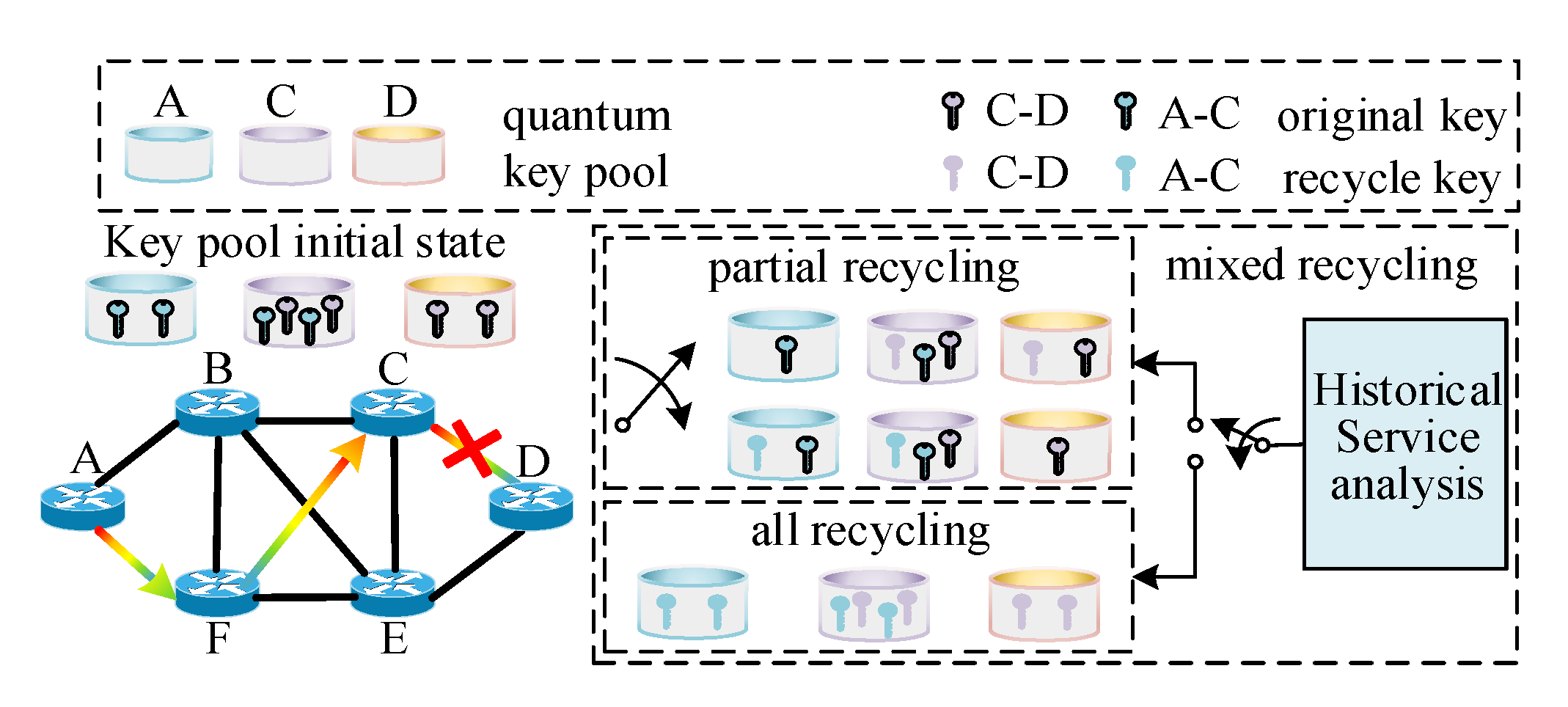
Figure 7 depicts the QKR algorithm and the state changes of the QKPs. A, C, and D are QKPs deployed on nodes A, C, and D respectively. Path A→F→C→D may be selected to serve the A–D node pair to share a key sequence. When the C→D relay process fails, the initial state of the key pool is as follows: QKP A and D, respectively, have two key sequences belonging to the A–C node pair and the C–D node pair. And there are four key sequences in QKP C, two of which belong to the A–C node pair and another two key sequences belonging to the C–D node pair. There are three types of recycling methods: partial recycling, all recycling, and mixed recycling.
The partial-recycling algorithm selects a pair of key sequences between the A–C key pair and the C–D key pair to recycle according to some decision factors, including the value of the key, the degree of the node pair, and so on. And the sequence of key pair that was not selected will be destroyed.
The all-recycling algorithm is to recycle both parts of the key, and then perform some post-processing operations on the recycled key such as mixing and transformation. However, this algorithm will bring additional consumption of the original key.
The mixed-recycling algorithm can achieve the balance between the security of the recovery key and the normal encryption of the original service. The mixed-recycling algorithm analyzes the historical data of the service and selects one from the partial recycling and the all-recycling algorithms, according to the characteristics of the historical service.
5.1. Partial Recycling
As shown in the Algorithm 1, when a data service arrives, a QKD service is generated, and then the key-relay path P
set is generated by the Dijkstra algorithm. When the relay process proceeds to node_current, the relay process fails, that is, the ‘node_begin-node_current’ key pair encrypted by the key pair ‘node_current-node_next’ cannot be decrypted successfully at node_next. However, at this time, we do not know whether the relay failure process is caused by the eavesdropper’s activity, and we either do not know whether the eavesdropper successfully obtained both the ‘node_begin-node_current’ and ‘node_current-node_next’ keys.
| Algorithm 1 Quantum Key Partial Recycling |
| 1: | For each data service Ser (Vs-d, Rsec, ts_s, thd) do |
| 2: | Generate QKD (Vs-d, ts_q, Nkey_relay, Pfailure, Tp); |
| 3: | For each QKD service QKD (Vs-d, ts_q, Nkey_relay, Pfailure, Tp) do |
| 4: | Pset←routing computation with D algorithm; |
| 5: | If flag bit shows relay failure &&KVb-c >= KVc-n then |
| 6: | Recycle key number(b,c) = Nkey_relay; |
| 7: | Else if flag bit shows relay failure && KVb-c < KVc-n then |
| 8: | Recycle key number(c,n) = Nkey_relay; |
| 9: | End if |
| 10: | End for |
| 11: | End for |
It is undoubtedly unsafe to directly recycle two pieces of keys at the same time. In this case, if the partial-recycling algorithm is used, it is necessary to define a parameter denoted by KV called ‘key value’ to evaluate which segment of the key needs to be recycled, which is expressed as:
The more relay nodes a key pair pass, the more relay keys are consumed, and therefore, the more the key pairs pass through the number of relay nodes, the more precious it is. Therefore, it is obviously wise to recycle the key pair with a high key value and destroy the other pair.
The advantage of this algorithm is that it has less impact on other services with encryption requirements, the recycling process is easy to implement, and the security of the recovery key is less dependent on the design of the algorithm. The disadvantage of this algorithm is that the security of the recovered key is low and some of the keys are not recycled.
Partial-recycling algorithm calls Dijkstra’s algorithm once and then performs a summation calculation with complexity O (1). Thus, Partial-recycling algorithm has a complexity of O(V2).
5.2. All Recycling
In order to improve the security of the recovery key and recover as many keys as possible, the quantum key all-recycling algorithm is designed as shown in Algorithm 2. In order to guarantee the security of the recycling key, the original key needs to be mixed into the recycling key. So, the first step of this algorithm is to set the mix ratio denoted by K
o/r and look up the capacity of the current original key. Then, according to the relationship:
where the maximum number of keys that can be recycled can be calculated. Finally, the algorithm recycles the key and performs post processing.
| Algorithm 2 Quantum Key All Recycling |
| 1: | For each data service Ser (Vs-d, Rsec, ts_s, thd) do |
| 2: | Generate QKD (Vs-d, ts_q, Nkey_relay, Pfailure, Tp); |
| 3: | For each QKD service QKD (Vs-d, ts_q, Nkey_relay, Pfailure, Tp) do |
| 4: | Pset←routing computation with D algorithm; |
| 5: | If flag bit shows relay failure && Ko/r *Nkey_relay >= Nkey(b,c) then |
| 6: | Nkey(b,c) -= Ko/r * Nkey(b,c); |
| 7: | Recycle key number(b,c)=(1+ Ko/r)* Nkey(b,c); |
| 8: | Else if flag bit shows relay failure && Ko/r *Nkey_relay < Nkey(b,c) then |
| 9: | Nkey(b,c) -= Ko/r *Nkey_relay; |
| 10: | End if |
| 11: | If flag bit shows relay failure && Ko/r *Nkey_relay >= Nkey(c,n) then |
| 12: | Nkey(c,n) -= Ko/r * Nkey(c,n); |
| 13: | Recycle key number(c,n)=(1+ Ko/r)* Nkey(c,n); |
| 14: | Else if flag bit shows relay failure && Ko/r *Nkey_relay < Nkey(c,n) then |
| 15: | Nkey(c,n) -= Ko/r *Nkey_relay; |
| 16: | Recycle key number(c,n)= (1+ Ko/r)*Nkey_relay; |
| 17: |
End if |
| 18: | End for |
| 19: | End for |
The post-processing phase disorders the recycled keys by linear adjustment or non-linear mapping to improve the security of the recycling key. Therefore, the security of the post-processing algorithm determines the security of the quantum key recycling algorithm and the post-processing algorithm brings the cost of the recovery algorithm to the use of the original key. The S-box has the following three characteristics: Each row of the table can traverse all possible values. Changing an input bit, changes at least two output bits, and the input and output are statistically independent. Therefore, in this paper, the design method of the S-box in the data encryption standard (DES) algorithm is used as a post-processing method for recycling the keys [
29,
30]. It is important that the two key pools that manage a pair of keys must perform the same post-processing strategy.
Post-processing is divided into three steps as shown in
Figure 8. Step 1: The key is mixed, and a certain proportion of the original key is inserted into the recycling key sequence according to the pre-defined insertion rules. Step 2: Extend the key mix sequence according to the rule of extended permutation table (②). Each 4-bit key is divided into a group (dark yellow area in the dotted line), and then a bit is added at the beginning and the end of the key group (light yellow area outside the dotted line). Step 3: The extended key sequence is nonlinearly compressed according to the rules of the S-box (③).
The advantage of the algorithm is that all keys are recycled as much as possible and the security of the recycled keys is high. The disadvantage of the algorithm is that the security of the recycled keys is mainly dependent on the design of the post-processing algorithm. And the post-processing algorithm may introduce the consumption of the original key, which may result in the original high-security-level service being unable to be encrypted.
The complexity of the all-recycling algorithm is mainly due to the call of Dijkstra’s algorithm and a post processing algorithm. The former can be achieved at a complexity of O (V2), and the latter has a complexity of O (Nkey), where Nkey is the number of keys being recycled. Thus, all-recycling algorithm has a complexity of max {O (V2), O (Nkey)}.
5.3. Mixed Recycling
The mixed QKR algorithm is proposed to maximize the average security of the service without affecting the original high security level of the service. As shown in Algorithm 3, the joint parameters obtained by analyzing historical traffic characteristics and used for adaptive selective-key-recovery algorithms are
,
, and
, respectively. x services before the current failed service are analyzed, where x is the number of historical data.
represents the weighted average security level of the service. a, b, c, and d are weighting coefficients. The closer the arrival time of the service is to the current time, the greater the weight.
| Algorithm 3 Quantum Key Mixed Recycling |
| 1: | For each data service Ser (Vs-d, Rsec, ts_s, thd) do |
| 2: | Generate QKD (Vs-d, ts_q, Nkey_relay, Pfailure, Tp); |
| 3: | Storage Nkey_relay and Rsec of the service; |
| 4: | For each QKD service QKD (Vs-d, ts_q, Nkey_relay, Pfailure, Tp) do |
| 5: | Pset←routing computation with D algorithm; |
| 6: | If flag bit shows relay failure && min {Nkey (i, j)} < && = =2 then |
| 7: | Call Algorithm 1; |
| 8: | Else if flag bit shows relay failure && min {Nkey (i, j)} > && = =3 then |
| 9: | Call Algorithm 2; |
| 10: | Else if flag bit shows relay failure && >= thv then |
| 11: | Call Algorithm 2; |
| 12: | Else if flag bit shows relay failure && < thv then |
| 13: | Call Algorithm 1; |
| 14: | End if |
| 15: | End for |
| 16: | End for |
represents the average demand for keys for a service with a security level of two in the history.
represents the variance of the key demand for the service with security level two.
The interplay between Algorithm 1 and Algorithm 2 can be changed by adjusting the calculation method and weighting coefficient of related parameters. The essence of the algorithm is a compromise algorithm, which relies on the analysis of historical services and adaptively makes the optimal recycling decision for the current network. Subsequent algorithm optimization can start with historical business analysis.
The complexity of the mixed-recycling algorithm consists of the analysis of historical services and the maximum complexity between Algorithms 1 and 2. To analyze historical services one needs to traverse the historical services twice, of which total amount is Nhist_ser, Algorithm 1 has a complexity of O (Nhist_ser), and the complexity of Algorithm 2 is O (V2) + O(Nkey). Thus, mixed-recycling algorithm has a complexity of max{O(Nhist_ser), O(V2) + O(Nkey)}.
6. Performance Evaluation and Analysis
In order to evaluate the performance of the key recovery algorithms, 14-nodes national science fund network (NSFNET) topology is used in simulation, as shown in
Figure 9. The costs of the links are related to the values of L
r.
The classification and characteristics of the services in the simulation are shown in
Table 2. Among the different service types, only low security level services can be encrypted using the recycled key in order to ensure the security quality. And when both the original key and the recycled key satisfy the encryption requirements of the service, the recycled key is used preferentially.
Table 3 shows the relative security factors for different types of keys. From the perspective of the source of the key, the original key is generated directly by QKD, so the original key is the safest and should be set to 1 compared to the recycled key. Part of the mixed-recycling key comes from the all-recycling key, and the other part comes from the partial-recycling key, so its relative security factor should be between the all-recycling-key security factor and the-partial-recycling key security factor. The specific value is related to the decision ratio of the mixed-recycling algorithm.
In order to reflect the value and cost of the QKR algorithm, the simulation results are divided into two categories. The first category expresses how the QKR algorithm optimizes the QKD network by showing the impact of different service failure rates (SFRs) and demonstrates the cost of deploying the QKR algorithm by showing the relative security level. The second category shows how the different algorithms are affected by the ratio of different security requirements and the rate of key generation. It also shows the balance of the algorithms and provides ideas for further optimization.
6.1. Comparative Analysis about Whether QKR Mechanism is Employed
Key utilization rate (KUR) and security coverage rate of service (SCR) were established as two indicators to evaluate QKD network performance. Key utilization rate indicates the ratio of the key used by the business to the total key amount, which is expressed as:
N
key_used indicates the number of keys successfully used by the service. N
key_leftover indicates the key stock of QKP at the end of the simulation and N
key_generated represents the amount of key generation for the entire run cycle of the simulation. Security coverage rate of service indicates the ratio between the number of services that the encryption requirement has satisfied and all services with encryption requirements, and is expressed as:
Nser indicates the total amount of service with security requirements. Nser_encrypted indicates the number of services that were successfully encrypted.
Figure 10a shows the trend of KUR and SCR with different service intensity (inflow of service per unit). It is obvious that regardless of the value of the service intensity, the KUR and SCR of the network are far superior to the algorithm without the QKR strategy than when using the QKR strategy. With the increase of service intensity, whether or not the QKR strategy is adopted, KUR is declining. Furthermore, the partial-recycling algorithm always stays ahead. On the other hand, the change in service intensity has no significant impact on the SCR for the algorithm of no recycling. However, as the service intensity grows, the SCR indicator of the key recycling algorithm is also growing.
Figure 10b indicates that the effect of SFR increase on KUR and SCR under all recycling, partial recycling, mixed recycling, and no-recycling algorithms. In the case of different SFRs, the three key-recycling algorithms are better than no recycling in both KUR and SCR.
Referring to the setting of the service security factor in
Table 3,
Figure 11 shows the relative security index of the service under different service numbers. The red line indicates that when no recycling is used, the relative security index of the service is always 1. This means that the key recycled by the QKR algorithm may not be as secure as the key directly generated by the traditional QKD. But it can provide encryption services for some businesses with low security requirements. Furthermore, the average relative security capability of the business has no obvious relationship with the number of services.
6.2. Comparative Analysis between Different QKR Algorithms
In this section, the performance gap between the three key-recovery algorithms of all recycling, partial recycling, and mixed recycling is compared.
Figure 12a illustrates that when the key-generation rate increases, no matter which recycling method is adopted, the security coverage of the service will increase. This is because the increase in key-generation rate means that more quantum keys can be used to provide security services. The partial-recycling algorithm performs best in this case because direct recycling does not affect the originally high security level of the business. Also, because the recycling key affects the original normal encryption service, the all-recycling algorithm performs the worst.
Figure 12b illustrates that the change in key-generation rate has no significant effect on key-utilization rate. This indicates that the key-generation rate is not the main factor affecting key utilization. However, it is obvious that the key-utilization rate of the three algorithms is higher than 90%. Partial recycling and mixed recycling performances are similar and slightly higher than all recycling.
As shown in
Figure 13a, the horizontal axis represents the ratio of the number of low-security-level data services to the number of high-security-level services. The larger the horizontal axis, the larger the proportion of low security level services. Both mixed recycling and all recycling show similar performances for KUR and SCR indicators. It may be because the decision made by the mixed algorithm based on the historical data service information tends to all recycling, resulting in a decrease in the proportion of the partial-recycling algorithm being adopted during the entire key-recovery process. In addition, SCR embodies the proportion of services successfully encrypted in the network, the granularity of the service is larger than the key, so the jitter of the SCR is greater than KUR.
Figure 13b present the balance of the key amount in the network after 100,000 data services. Both the x-axis and the y-axis represent the node number, and the xy plane determines the logical position of the QKP. The z-axis represents the ratio of the QKP key amount to the minimum key amount of all QKPs. In general, due to the design of the key-relay routing algorithm, the three recycling methods do not perform well in terms of balance. However, compared to the other two recycling algorithms, the mixed-recycling algorithm performs best in terms of balance, while the all-recycling algorithm performs the worst. For the all-recycling algorithm, the poor equalization provides an optimized direction for the optimization of the algorithm. Since the most important factor affecting the performance of the all-recycling algorithm is the consumption of the original key, the unbalanced key amount can just provide the original for the all-recycling algorithm through the relay, thereby improving the performance of the algorithm.
7. Conclusions
With the fundamental purpose of improving key utilization, this paper proposes quantum-key recycling mechanisms in QKD network to increase the number of available keys in the system and further improve the security-coverage rate of the service. The paper also establishes different service security levels, and match different levels of keys and encryption algorithms for services of different security levels, so that the keys are effectively used. Compared with the traditional QKD network with no-recycling algorithm, partial recycling and all recycling have obvious advantages for both KUR and SCR under different service strengths and business failure rates. The performance improvement for KUR indicators is higher than 10%, and the SCR index is increased by about 20%. The mixed-key-recycling strategy is superior to all-key-recycling mechanisms in terms of KUR and SCR, and is equal to or slightly lower than that of partial-key-recycling mechanisms. In order to measure the impact of the key recycling mechanism on network security, a key security factor is designed. The security factor for three key recycling algorithms are all higher than 0.9, and the mixed-key recycling mechanism is higher than the partial-key recovery mechanisms. The three key-recycling algorithms are not optimized for the load balancing of the security services of the network. Some key pools carry a small number of services, resulting in a large number of key accumulations. These accumulated keys can be used to provide the original key for partial-key recycling. While improving the key-recycling rate and reducing the service-blocking rate, it is one of the subsequent optimization directions of the QKR mechanism.


