1. Introduction
The majority of low-voltage distribution systems are unbalanced, mainly owing to the use of single-phase loads. In transmission systems or high-voltage systems, these effects are also present but they are very small. The phenomenon of imbalance causes unbalanced powers. The unbalanced powers constitute inefficiencies in the system [
1,
2,
3,
4] that cause increased losses in the lines and the malfunction of motors, generators, transformers, and protective equipment. In addition, the apparent power of the system is significantly increased [
5,
6,
7,
8]. Therefore, the powers due to imbalances must be calculated properly to facilitate the reliable design of active, passive, or hybrid devices, which can be used to compensate for them.
At present, there is no theory agreed on by all that allows an adequate evaluation of this type of phenomenon [
9]. Most of the studies that exist focus on using the expressions proposed in the standard IEEE Std. 1459-2010 [
10] and Buchholz [
11]. These expressions use the Root Mean Square (RMS) values of the voltage and current that are expressed in symmetric or phase components. As a result, the moduli or RMS values of the apparent power and unbalanced power are obtained at a bus in the system [
12]. These values are perfectly valid, but they are insufficient for accurate evaluation and analysis of the causes of the imbalance, as well as the place where they occur. In certain cases, the imbalances at a node of the system can help to compensate for some of the imbalances at another node [
13,
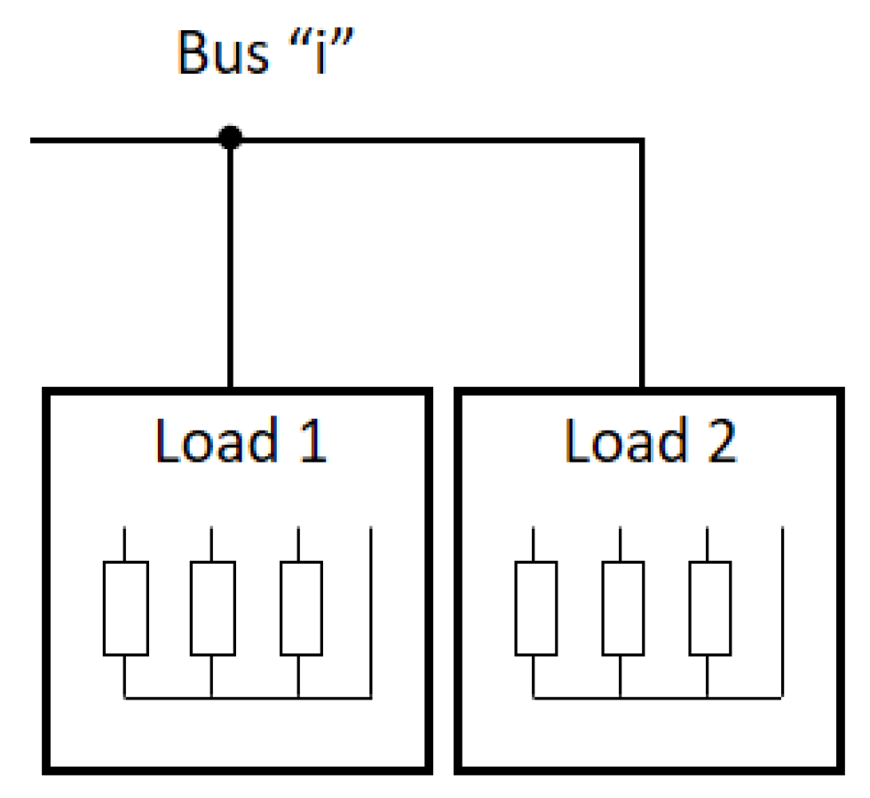
14]. This type of case cannot be analysed correctly if we only know the moduli of the unbalanced powers, for example, when one knows the individual unbalance powers of two loads connected in parallel and one wants to calculate the unbalanced power that results from the coupling since the resulting unbalanced apparent power is not the arithmetic sum of both.
There are other studies that have proposed phasor or vector expressions to evaluate these inefficiencies. In [
15], vector apparent power is defined as the vector sum of total active, total reactive, and total distortion powers, which are the sum of respective values for each phase. It treats each phase as an independent single-phase system like arithmetic apparent power. In this study, the unbalance power is not proposed by means of a vector expression. In [
16], the unbalanced power vectors due to voltage and current are defined. To consider the unbalanced voltages, they use the unbalance factors
and
. In [
17], the authors propose a new tool to phasorically represent the powers in the Clifford geometric space that is only applied to single-phase systems. In [
18], the phasor of the total unbalance power is defined. It presents the same problem as [
16] since they use the unbalance factors
and
to consider the unbalance power caused by the unbalanced voltages. Other authors extend their studies to the analysis of non-linear three-phase systems [
19,
20].
The use of these expressions significantly improves the capacity in the analysis of unbalanced phenomena and adapts correctly to systems fed with balanced voltages. Its application in systems with unbalanced voltages is based on including scalar expressions, such as factors and . These scalar values diminish the capacity of analysis of vector expressions, making necessary their determination at any node of the system as we cannot use the vector properties that relate one node to another. Therefore, the unbalanced powers caused by the asymmetry of the voltages are not adequately considered. For this reason, when the voltages are unbalanced, it is also not possible to determine whether the compensation of the unbalanced powers at one node of the system improves or worsens the rest of the system.
The main objective of this paper is to propose the vector expressions necessary to quantify the unbalanced powers and, as a consequence, the total apparent powers of an unbalanced three-phase linear system. These expressions are valid for perfectly analysing systems with balanced and unbalanced voltages y, and in both cases, it allows us to develop passive compensators for unbalance powers due to negative and zero-sequence currents [
21,
22]. The modulus of the total apparent power obtained at any node in the system coincides with the apparent power of Buchholz. This value determines the maximum transferable power for each voltage waveform [
23], including all efficient and non-efficient powers [
24]. The components of these vectors are defined from terms of active and reactive power per phase; in this way, the same component of the vectors between two system buses or between loads connected in parallel can be arithmetically added to each other. From these expressions, it is possible to mainly analyze the unbalanced power flows in any electrical system. This allows, facing a change or variation in the system, analyzing the positive or negative contribution that this variation represents on the unbalance power and, as a consequence, its repercussion on the total apparent power on any bus of the system. Accordingly, in
Section 2, based on the Buchholz power, the apparent power and unbalanced power of any system are analysed and studied for both balanced and unbalanced voltages. In
Section 3, the new vector expressions of the apparent power are formulated. In
Section 4, from the expressions deduced in the previous section, vector expressions of unbalanced power are formulated. In
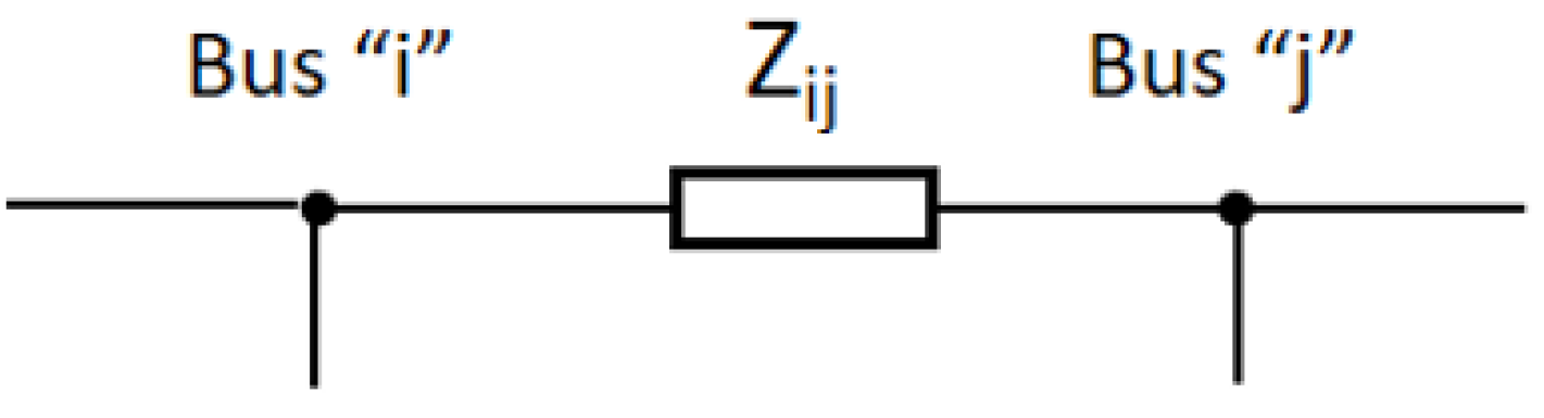
Section 5, the two typical cases to be considered in the use of the vectors of the apparent power and the vectors of the unbalanced power are studied: application to a bus with loads connected in parallel and application between two buses of the system united by a line. In
Section 6, the formulation of the apparent power vector is extended to non-linear systems to determine the harmonic apparent power of the system. To help understand the use of these vector expressions, a practical case of a three-phase four-wire system with unbalanced loads and voltages is discussed in
Section 7.
3. Apparent Power Vectors Proposed
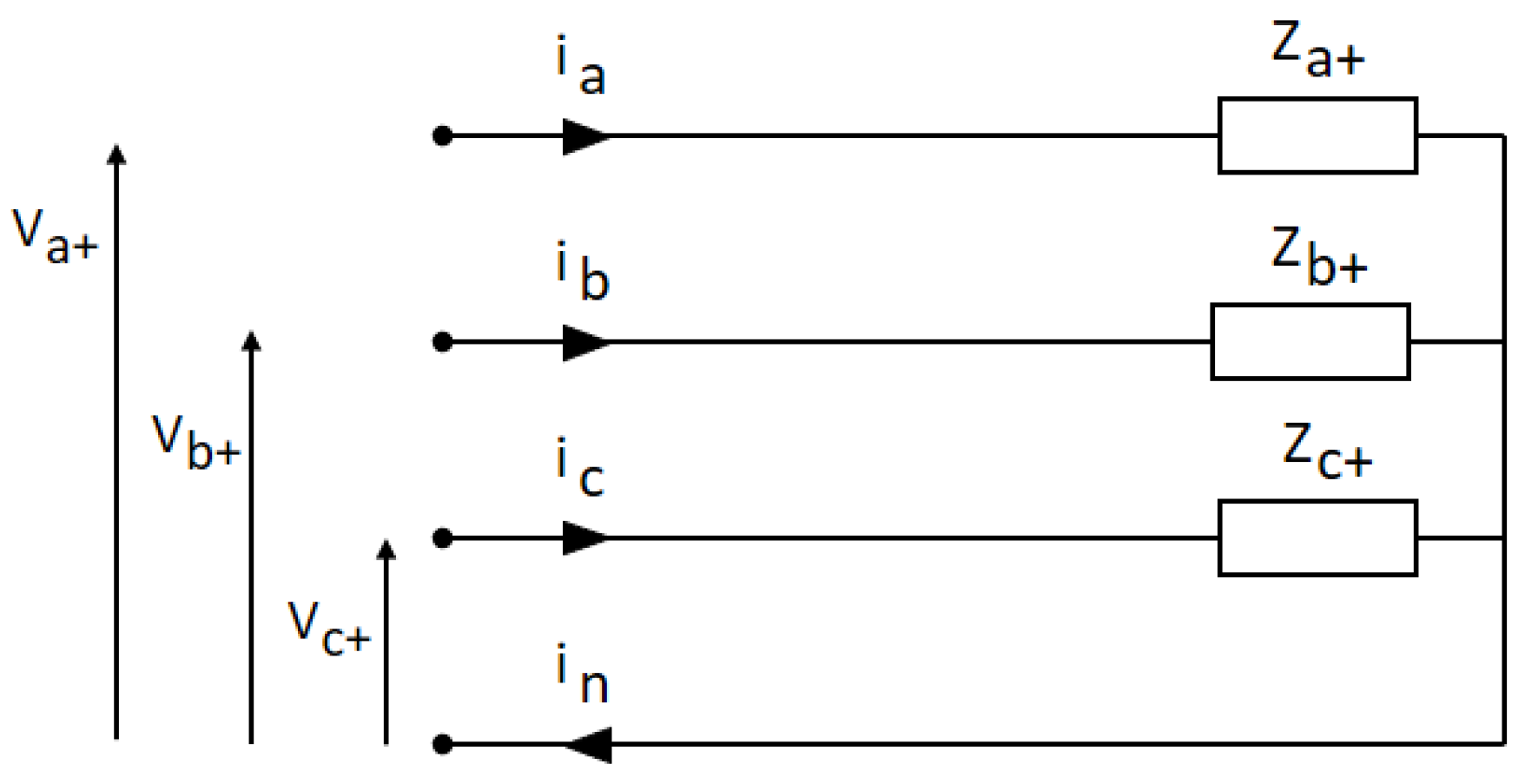
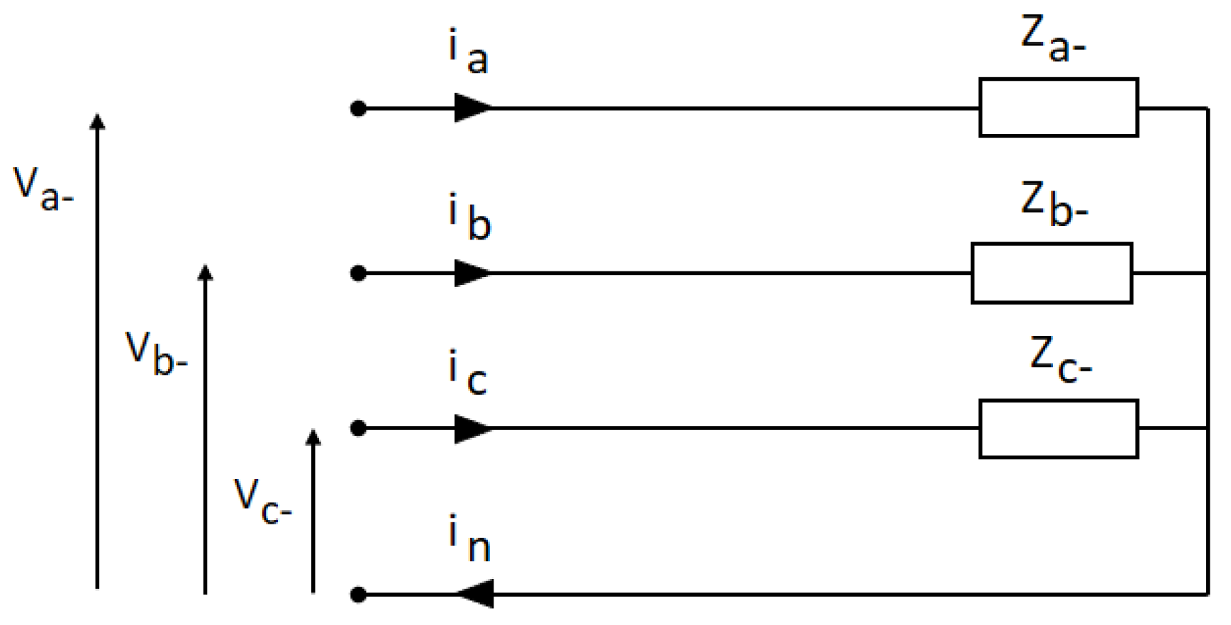
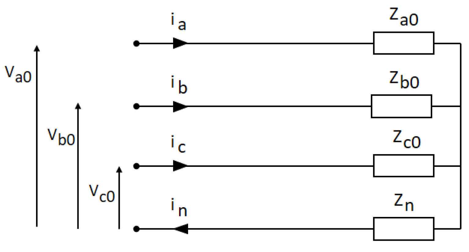
As described in the previous sections, from the symmetric components of voltages, any unbalanced linear three-phase system is divided into three linear three-phase systems.
,
, and
are the apparent powers in each of these three systems, and their RMS values are calculated from (19), (22), and (23). Each of these expressions can be expressed in vector form three apparent power vectors: positive-sequence voltage apparent power vector
, negative-sequence voltage apparent power vector
, and zero-sequence voltage apparent power vector
. Each of these vectors has six components that are orthogonal to each other and are determined from the following expressions:
where
and are the unit vectors that are associated with the six components of the apparent power vector due to the positive-sequence voltage. These unit vectors are perpendicular to each other.
and are the unit vectors that are associated with the six components of the apparent power vector due to the negative-sequence voltage. These unit vectors are perpendicular to each other.
and are the unit vectors that are associated with the six components of the apparent power vector due to the zero-sequence voltage. These unit vectors are perpendicular to each other.
The total apparent power according to (3) is calculated from the vector moduli , , and .
Moreover, active power
and reactive power
, used in the classical theories, are determined by the arithmetic sum of all the components of their nature, their expressions being the following:
4. Unbalanced Power Vectors Proposed
In a linear three-phase system balanced in voltages and currents, the negative sequence and zero sequence currents and voltages are null. Under these conditions, the total apparent power of the system is determined exclusively from the positive-sequence currents and voltages. This apparent power is called the apparent positive-sequence power . Positive-sequence active power and positive-sequence reactive power are calculated from (16) and (17).
If we consider these powers in each phase, the following conditions are satisfied:
In an unbalanced linear three-phase system [
10], the only apparent power that is not due to the imbalance of the voltages and currents is the positive sequence apparent power
; the rest of the apparent powers are caused by imbalances, representing the unbalanced apparent power. As in the previous section, unbalanced power is defined from three vectors: vector of unbalanced apparent power of positive-sequence voltage
, vector of unbalanced apparent power of negative-sequence voltage
, and vector of unbalanced apparent power of zero-sequence voltage
. The vectors
and
, according to (29) and (30), represent only the unbalanced powers; therefore,
and
. The vector
includes
, which is not an unbalanced power; therefore, to obtain
, the corresponding values of
and
, which according to (33) and (34) are equal to one-third of its value, must be subtracted in each of its components, as in (35), where
.
The modulus of unbalanced apparent power is given by
The total unbalanced apparent power
according to (37) is calculated from the vector moduli
,
, and
.
Therefore, the apparent total power is given by (38).
Additionally, if we express the line currents in symmetric components, the total apparent power is determined by (39).
Following the same procedure as in previous sections, the apparent powers of any of the nine addends of the square root can be expressed by means of its vector expression according to (40) and its moduli from (41). Here
indicates the symmetric component of the voltage and
indicates the symmetric component of the current. When the symmetrical components of voltage and current are the same in (39), we have indicated it only with the subscript, therefore in (40) and (41);
,
and
. On the other hand,
and
are the unit vectors associated with each active and reactive component, respectively.
With these vectors, it is easy to analyse the electrical systems knowing the individual vectors in each of the loads. In the practical case of
Section 7, the simplicity in the use of the proposed vectors is observed.
Furthermore, the decomposition of the apparent powers in different sequences helped the authors to obtain a passive compensator for the negative sequence current [
21], treating the reactive power
in a similar way to the compensation of the positive-sequence reactive power. It was also applied to the development of a passive compensator for the zero-sequence current consumed by the load [
22]. These compensators respond correctly for both balanced and unbalanced voltages.
6. Extension to Non-Sinusoidal Three-Phase Power Systems
The unbalanced apparent power in an unbalanced three-phase system according to [
10] is only due to the fundamental components of the currents and voltages, whereas in a non-linear system, powers that are not due to the fundamental harmonics of current and voltage are considered harmonic apparent powers.
Consider a three-phase nonlinear system, where
is the per-phase voltage of harmonic order m and
is the per-phase current of harmonic order n where
z = {
a,
b,
c}. If we extend the vector expressions (28)–(30) that have been defined in previous sections for
m =
n = 1 to the remaining harmonic combinations of
m and
n, that is, for each
m ≠
n and
m =
n ≠ 1, we obtain the harmonic vectors expressions according to (66)–(68).
,
, and
are the harmonic powers caused by the positive-, negative-, and zero-sequence voltages of order
m and the currents of order
n. Its moduli are determined from the expressions (69)–(71).
, , , , , and are the unit vectors associated with each component.
,
, and
are the per-phase harmonic active powers caused by the positive-, negative-, and zero-sequence voltages, respectively, of order
m and the currents of order
n. Their values are determined by (72), where
.
,
, and
are the per-phase harmonic reactive powers caused by the positive-, negative-, and zero-sequence voltages, respectively, of order
m and the currents of order
n. Their values are determined by (73), where
.
For each harmonic of voltage of order
m and harmonic of current of order
n, the harmonic apparent power is given by (74).
The total harmonic apparent power is given by
Therefore, the total apparent power of the system
is given by (76), and its value coincides with [
10].
7. Practical Application
In this section, a practical case study to verify all of the concepts discussed in the previous sections is developed.
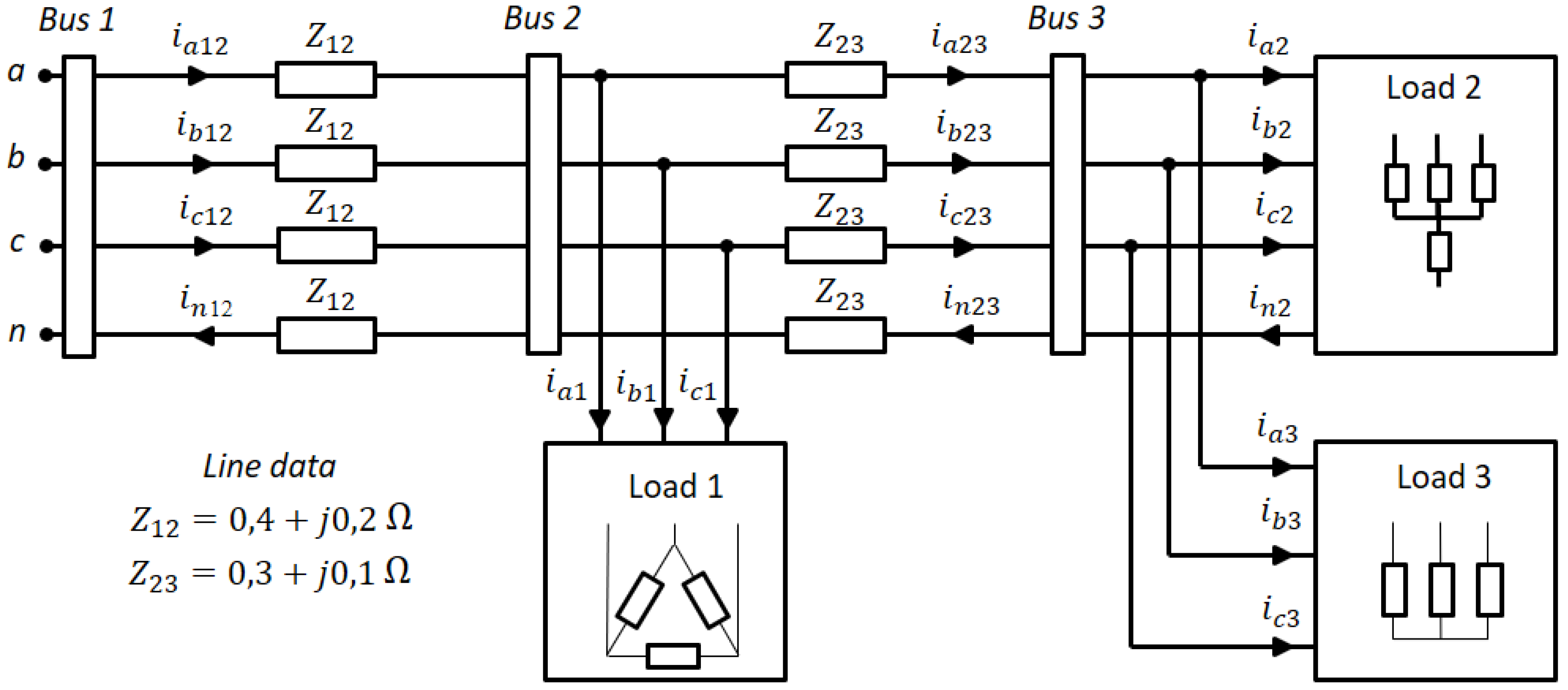
Figure 7 shows a three-phase, four-wire electrical system with three unbalanced three-phase linear loads. The loads are modelled at a constant impedance. The impedance values of loads are listed in
Table 1,
Table 2 and
Table 3. The voltages are unbalanced and sinusoidal in bus 1 (slack bus), in which
Using the ‘PSPICE’ analysis software, the line-to-neutral voltages in the buses (1, 2, and 3) and the currents circulating in the loads are obtained. These magnitudes are displayed in
Table 4 and
Table 5.
Table 6 shows the voltages expressed in symmetric components for each of the nodes of the system. These values are referred to as phase A.
Table 7 shows the values of the components that form the vectors of the apparent power and unbalanced power, considering the positive-sequence voltage. To calculate
and
, expressions (16) and (17) have been used. For
and
, expressions (33) and (34) have been used.
Table 8 shows the values of the components that form the vectors of apparent power and unbalanced power, considering the negative-sequence voltage. To calculate
and
, expressions (24) and (25) have been used.
Table 9 shows the values of the components that form the vectors of apparent power and unbalanced power, considering the zero-sequence voltage. To calculate
and
, expressions (26) and (27) have been used.
Finally,
Table 10 and
Table 11 show the moduli of the apparent power vectors and unbalanced power vectors, respectively.


