Behavior of Longitudinal Plate-to-Rectangular Hollow Structural Section K-Connections Subjected to Cyclic Loading

Abstract
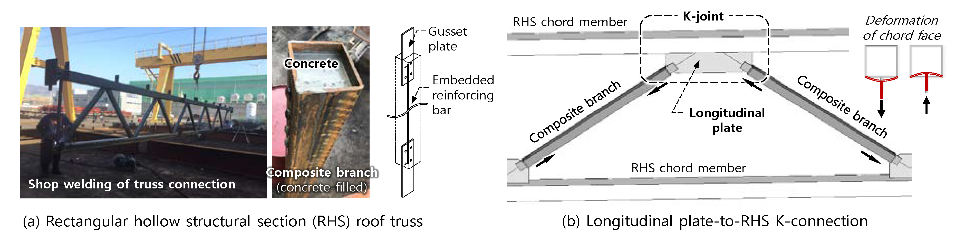
:1. Introduction
2. Theoretical Strength of Plate-to-RHS Connections
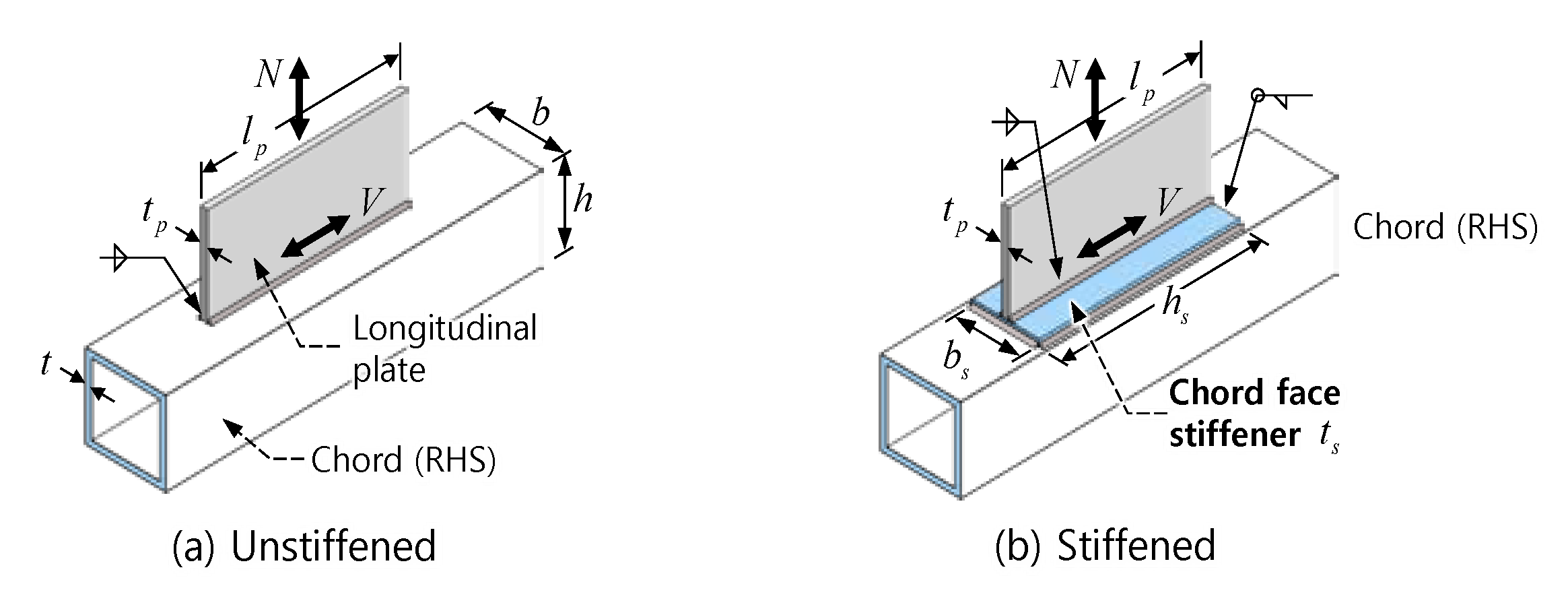
2.1. Connection Without Stiffener
2.2. Connection With Chord Face Stiffener
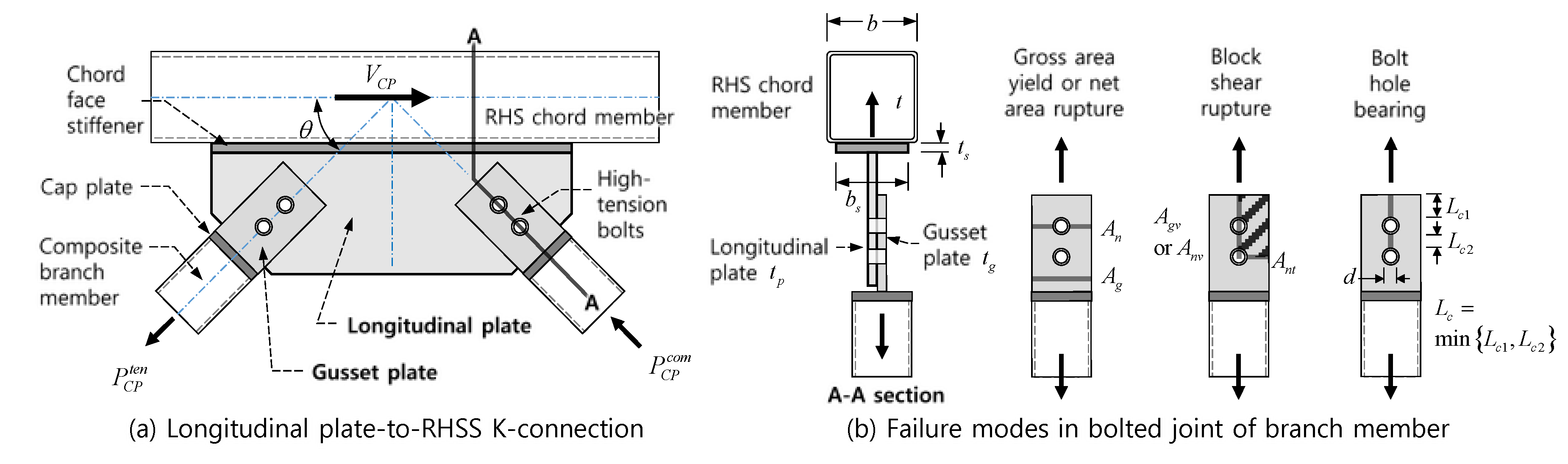
2.3. Bolted Joint of Branch Member
3. Test Program
3.1. Specimen Details
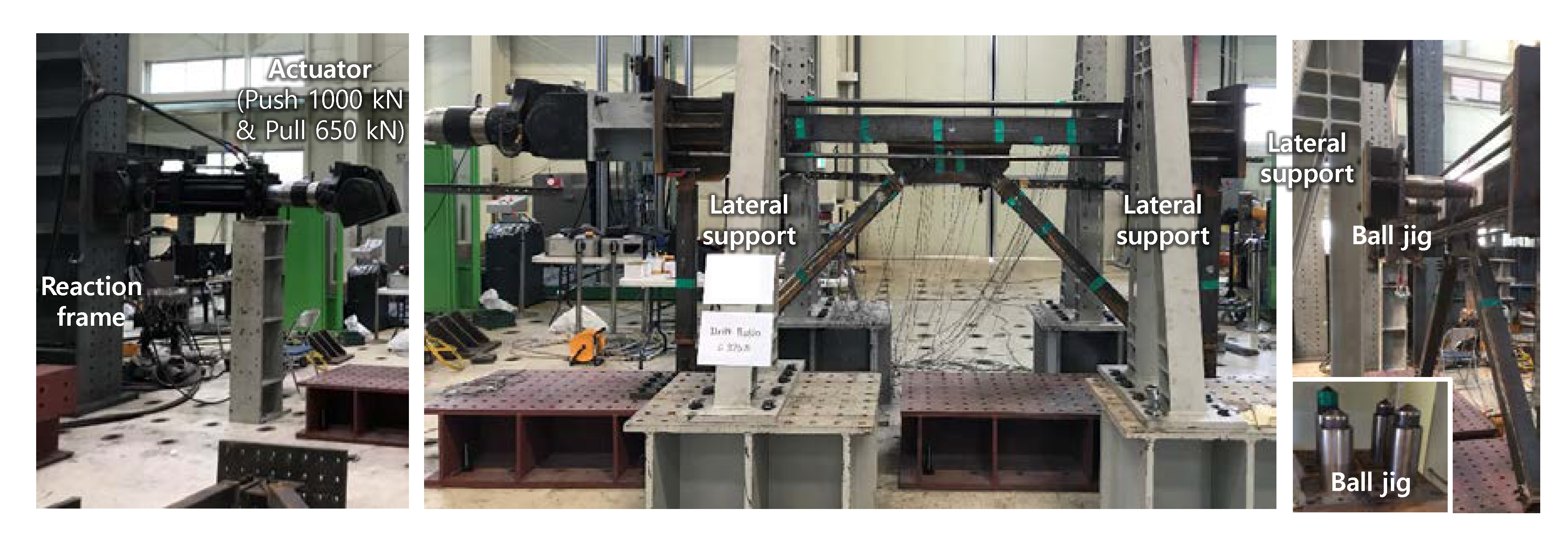
3.2. Material Strength and Test Setup
3.3. Check for Limits of Applicability
- The steel yield strength of the chord member, Fy = 405 MPa, exceeded the upper limit of 360 MPa in AISC 360-10. According to the CIDECT Design Guide 3, the steel yield strength was smaller than the upper limit of 460 MPa. The yield ratio, Fy/Fu = 405/503 = 0.805, was slightly greater than the upper limit of 0.8.
- In all specimens, the yield strength of the longitudinal plate, Fyp = 429 MPa, did not satisfy the requirement of the CIDECT Design Guide 3, Fyp ≤ Fy (=405 MPa). For the longitudinal plate under shear force parallel to the chord axis, AISC 360-10 limits Fyp to be not greater than Fut/tp to prevent punching shear failure on the connecting chord face. However, for N00–150, Fyp was significantly larger than Fut/tp (=503·4.5/15 = 151 MPa).
- For S25-200, the wall width-to-thickness ratio of the chord member, b/t = 44.4, was slightly greater than the upper limit of 40 in AISC 360-10 and CIDECT Design Guide 3. On the other hand, the ratios of the chord width to the branch width, bb/b = 0.667 and 0.5, were smaller than the upper limit of 0.85 in AISC 360-10, and the ratios of the stiffener width to the chord width, bs/b = 0.8 and 0.85, did not exceed 0.85.
- For N00-150 and S15–150, the ratio of the plate length to the chord width, lp/b = 4.67, exceeded the upper limit of 4 in the CIDECT Design Guide 3. On the other hand, for S25-200, lp/b = 3.5 was within the limit.
- The minimum thickness of chord face stiffener computed by Equation (5) was 19.6 mm for S15-150 (provided thickness ts = 15 mm) and 24.3 mm for S25-200 (provided thickness ts = 25 mm). Thus, S15-150 did not satisfy the requirement.
4. Test Results
4.1. Load-Displacement Relationship and Failure Mode
4.2. Effects of Chord Face Stiffener
5. Strength Evaluation
5.1. Theoretical Strengths
5.2. Comparison Between Theoretical and Test Strengths
- (1)
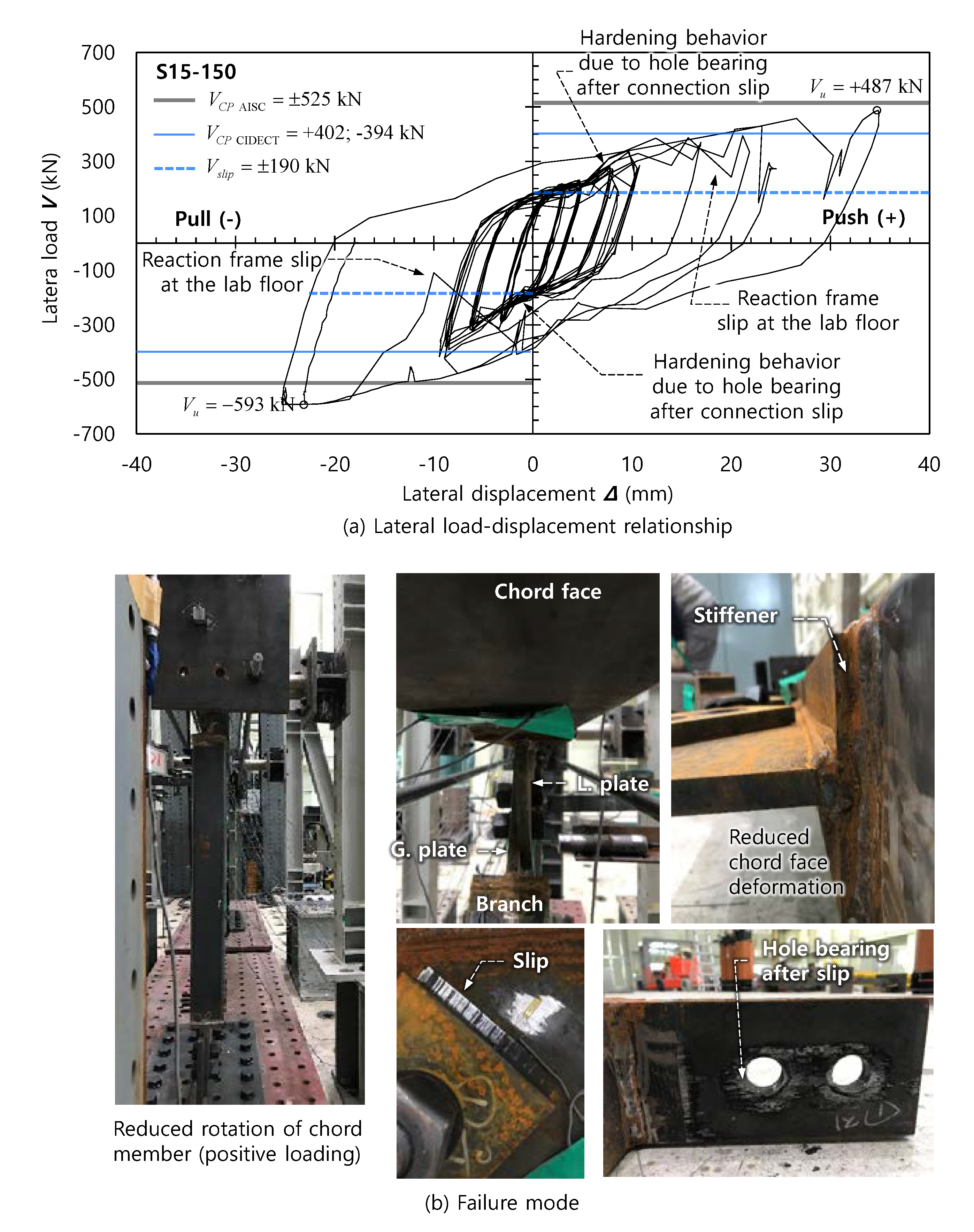
- In all specimens, the maximum loads Vu were greater than Vslip (=190 kN), which was the slip resistance of the bolted joint of the branch members. Thus, in the load-displacement curves in Figure 6, Figure 7 and Figure 8, the stiffness degradation or slip behavior occurred roughly at the load levels of V = ±190 kN. However, the post-slip ultimate strength VSB (= 723 kN) was greater than the maximum loads. This explains why hole bearing failure did not occur at the bolted joint while threaded marks or dents were left on the inner face of the hole (see Figure 7b and Figure 8b).
- (2)
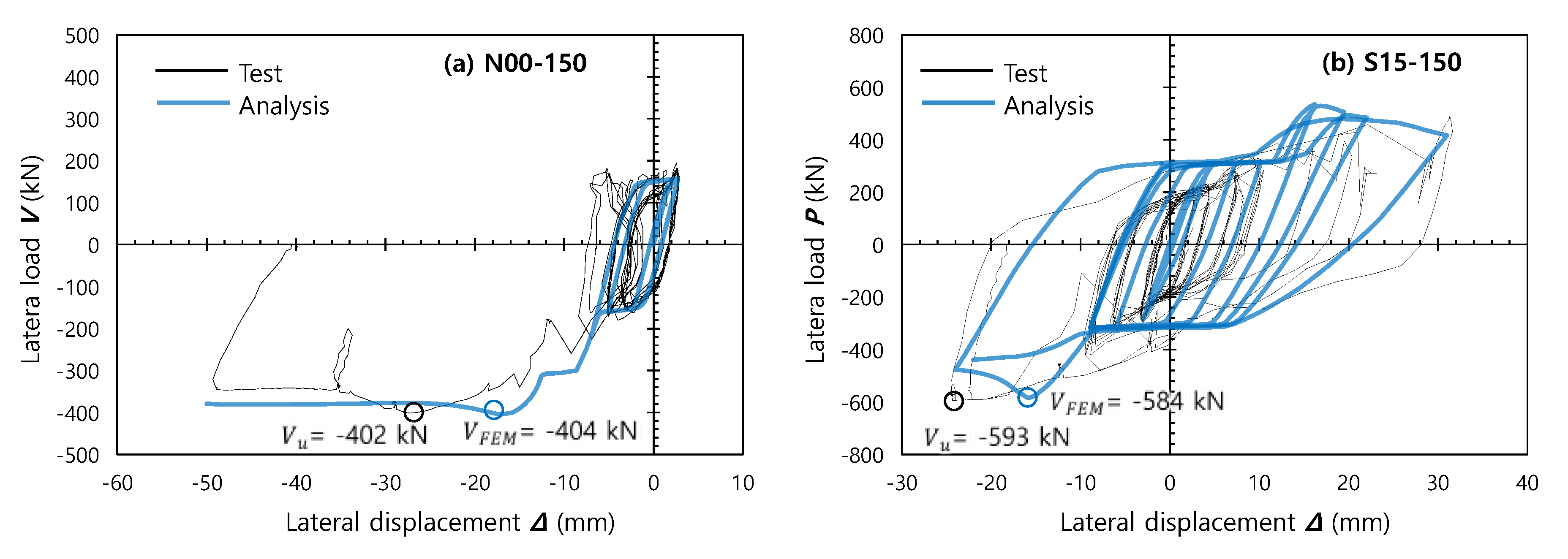
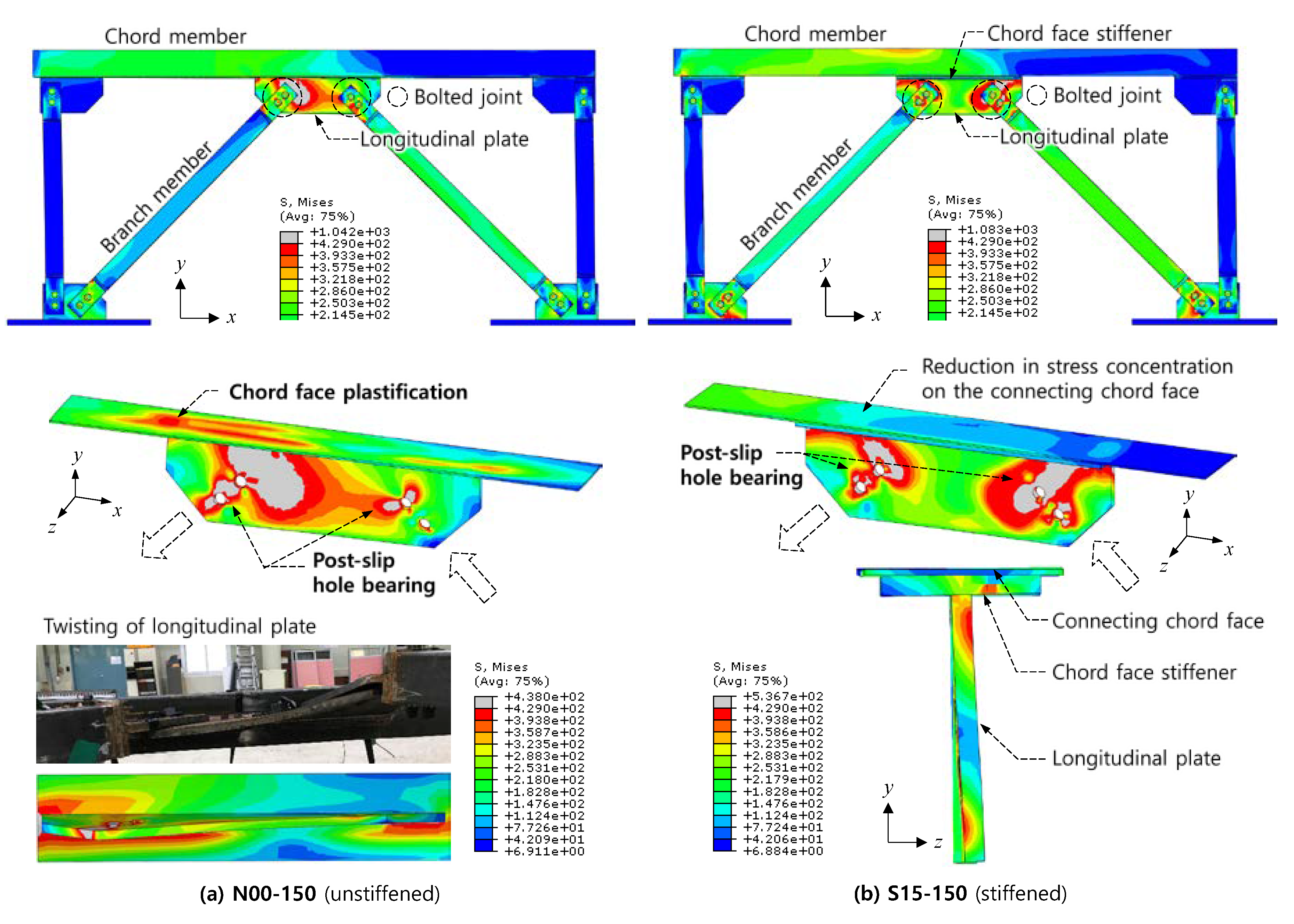
- For N00-150, VCP of AISC 360-10 and CIDECT Design Guide 3 (= −149 kN and −132 kN, respectively) was less than Vslip (=190 kN). This indicates that the behavior of the unstiffened plate-to-RHS K-connection was governed by chord face plastification. Basically, the chord face plastification was a ductile failure mode accompanying hardening behavior, as reported in the previous studies by Packer, Cao, and Kosteski [6,7]. Thus, during negative loading, the strength significantly increased with increasing displacement. Consequently, the maximum load in the negative direction, Vu = −402 kN, was much larger than VCP.
- (3)
- For S15-150 and S25-200 with the stiffened plate-to-RHS K-connections, the overall behavior was governed by chord face plastification after connection slip at the bolted joint of the branch members. Overall, both AISC 360-10 and CIDECT Design Guide 3 gave reasonable estimates on the chord face plastification strengths VCP of the stiffened connections. AISC 360-10 overestimated the connection strength; the test-to-theoretical strength ratio was Vu/VCP = 1.13 for S15-150 (= −593 kN/−525 kN) and 0.93 for S25-200 (= −602 kN/−644 kN). On the other hand, the CIDECT Design Guide 3 underestimated the connection strength; Vu/VCP = −593 kN/−394 kN = 1.51 for S15-150 and Vu/VCP = −602 kN/−463 kN = 1.30 for S25-200.
6. Finite Element Analysis
7. Summary and Conclusions
- (1)
- The plate-to-RHS K-connections exhibited the deformation-controlled hardening behavior dissipating considerable energy after slip occurred at the bolted joint of branch members. Overall, the joint behavior was flexible due to out-of-plane deformations of the connecting chord face and longitudinal plate, and thus, there was not brittle failure such as weld rupture.
- (2)
- The behavior of the plate-to-RHS K-connections stiffened by chord face stiffeners was governed first by slip at the bolted joint of branch members and then by the plastification of the connecting chord face. For S15-150 and S25-200, as the chord face stiffener reduced the deformation of the connecting chord face, the initial stiffness and ultimate strength were greatly increased.
- (3)
- The provisions of current design codes, such as AISC 360-10 and CIDECT Design Guide 3, yielded a reasonable estimate of the chord face plastification strength of plate-to-RHS K-connections. The CIDECT Design Guide 3 resulted in the conservative estimate of the connection strengths, whereas AISC 360-10 slightly overestimated the strength of the stiffened connections.
- (1)
- In the first phase, the plate-to-RHS connections are designed for unfactored service loads (i.e., serviceability limit state). The governing limit state of the truss connections is connection slip at the bolted joint of branch members.
- (2)
- In the second phase, the plate-to-RHS connections are designed for factored loads at the ultimate limit state. The governing limit state of the truss connections is the plastification of connecting chord face. The bolted joint of branch members should be checked for post-slip failure modes, such as hole-bearing failure and block shear rupture.
Author Contributions
Funding
Conflicts of Interest
References
- American Institute of Steel Construction. Specification for Structural Steel Building; AISC 360-16; American Institute of Steel Construction: Chicago, IL, USA, 2016. [Google Scholar]
- American Institute of Steel Construction. Specification for Structural Steel Building; AISC 360-10; American Institute of Steel Construction: Chicago, IL, USA, 2010. [Google Scholar]
- CEN (European Committee for Standardization). Design of Steel Structures. Part 1.8: Design of Joints; Eurocode 3; CEN: Brussels, Belgium, 2005. [Google Scholar]
- Packer, J.A.; Wardenier, J.; Zhao, X.-L.; van der Vegte, G.J.; Kurobane, Y. Design Guide for Rectangular Hollow Section (RHS) Joints under Predominantly Static Loading, 2nd ed.; CIDECT Design Guide 3; Comité International pour Ie Développement et l’Étude de la Construction Tubulaire: LSS Verlag: Köln, Germany, 2009. [Google Scholar]
- Kosteski, N.; Packer, J.A.; Puthli, R.S. A finite element method based yield load determination procedure for hollow structural section connections. J. Constr. Steel Res. 2003, 59, 453–471. [Google Scholar] [CrossRef]
- Cao, J.J.; Packer, J.A.; Kosteski, N. Design Guidelines for Longitudinal Plate to HSS Connections. J. Struct. Eng. 1998, 124, 784–791. [Google Scholar] [CrossRef]
- Kosteski, N.; Packer, J.A. Longitudinal Plate and Through Plate-to-Hollow Structural Section Welded Connections. J. Struct. Eng. 2003, 129, 478–486. [Google Scholar] [CrossRef]
- Kosteski, N.; Packer, J.A. Welded Tee-to-HSS Connections. J. Struct. Eng. 2003, 129, 151–159. [Google Scholar] [CrossRef]
- Cao, J.J.; Packer, J.A.; Kosteski, N. Yield line analysis of HSS connections with axial loads. J. Constr. Steel Res. 1998, 48, 1–25. [Google Scholar] [CrossRef]
- Park, K.S. Ultimate Strength of T-and N-Joints of Trusses with Square Hollow Structural Sections. Ph.D. Thesis, Hanyang University, Seoul, Korea, 2006. [Google Scholar]
- Dassault Systemes Simulia Corp. Abaqus/CAE User’s Guide v. 6.14; Dassault Systemes Simulia Corp: Providence, RI, USA, 2014. [Google Scholar]
- Kulak, G.L.; Fisher, J.W.; Struik, J.H.A. Guide to Design Criteria for Bolted and Riveted Joints, 2nd ed.; American Institute of Steel Construction, Inc.: Chicago, IL, USA, 2001. [Google Scholar]
- Lim, J.J. Structural Performance of Concrete-Filled Thin-Walled Tube Columns, Column Splices, and Beam-to-Column Connections. Ph.D. Thesis, Dankook University, Yongin, Korea, 2018. [Google Scholar]


| Design code | AISC 360-10 | CIDECT Design Guide 3 | |
| Chord member | Yield strength | Fy ≤ 360 MPa | Fy ≤ 460 MPa 3) |
| Yield ratio | Fy/Fu ≤ 0.8 | Fy/Fu ≤ 0.8 4) | |
| Width-to-thickness ratio | b/t ≤ 40 1) | b/t ≤ 40 and h/t ≤ 40 5) | |
| Height-to-width ratio | - | 0.5 ≤ h/b ≤ 2.0 | |
| Longitudinal plate | Yield strength | Fyp ≤ Fu (t/tp) 2) | Fyp ≤ Fy |
| Length | - | 1 ≤ ηp (=lp/b) ≤ 4 | |
| Joint Type | AISC 360-10 | CIDECT Design Guide 3 | |
|---|---|---|---|
| Plate-to-RHS connection | T- and Y-connections | 1) | where C1 = 0.2 for n < 0 and 0.1 for n ≥ 0 2) |
| RHS-to-RHS connection | T-, Y-, and K-connections | 1) | where C1 = 0.6-0.5(bs/b) (T- and Y- connections) or 0.5-0.5(bs/b) (K-connections) for n < 0 and 0.1 for n ≥ 0 2) |
| Specimen | Type | Chord Member | Longitudinal Plate | Chord Face Stiffener | |
|---|---|---|---|---|---|
| N00-150 | Unstiffened | b = 150 mm; b/t = 33.3 | lp = 700 mm tp = 15 mm | lp/b = 4.67 | - |
| S15-150 | Stiffened | b = 150 mm; b/t = 33.3 | lp/b = 4.67 | bs = 120 mm; ts = 15 mm; bs/b = 0.8 | |
| S25-200 | Stiffened | b = 200 mm; b/t = 44.4 | lp/b = 3.5 | bs = 170 mm; ts = 25 mm; bs/b = 0.85 | |
| Type | Member | Yield Strength (MPa) | Ultimate Strength (MPa) | |
|---|---|---|---|---|
| RHS | 4.5 mm | Chord | 405 | 503 |
| 4.0 mm | Branch | 395 | 508 | |
| Plate | 15 mm | Longitudinal plate and stiffener | 429 | 574 |
| 25 mm | Stiffener | 328 | 519 | |
| Bolt | M24 | Bolted joint of branch | 1040 | 1102 |
| Bar | D10 | Branch | 511 | 665 |
| Specimen | Chord Face Plastification Strength VCP (kN) 1) | Bolted Connection Strength (kN) | ||||
|---|---|---|---|---|---|---|
| AISC 360-10 | CIDECT Design Guide 3 | Slip | Post-slip ultimate | |||
| Positive 2) | Negative 2) | Positive 2) | Negative 2) | Vslip | VSB (=Vslip + Vbearing) | |
| N00-150 | +154 | −149 | +135 | −132 | 190 | 723 (=190 + 533) |
| S15-150 | +525 | −525 | +402 | −394 | 190 | 723 (=190 + 533) |
| S25-200 1) | +644 | −644 | +479 | −463 | 190 | 723 (=190 + 533) |
© 2020 by the authors. Licensee MDPI, Basel, Switzerland. This article is an open access article distributed under the terms and conditions of the Creative Commons Attribution (CC BY) license (http://creativecommons.org/licenses/by/4.0/).
Share and Cite
Yoon, T.-H.; Eom, T.-S.; Kim, C.-G.; Kang, S.-M. Behavior of Longitudinal Plate-to-Rectangular Hollow Structural Section K-Connections Subjected to Cyclic Loading. Appl. Sci. 2020, 10, 3793. https://doi.org/10.3390/app10113793
Yoon T-H, Eom T-S, Kim C-G, Kang S-M. Behavior of Longitudinal Plate-to-Rectangular Hollow Structural Section K-Connections Subjected to Cyclic Loading. Applied Sciences. 2020; 10(11):3793. https://doi.org/10.3390/app10113793
Chicago/Turabian StyleYoon, Tae-Hyun, Tae-Sung Eom, Chul-Goo Kim, and Su-Min Kang. 2020. "Behavior of Longitudinal Plate-to-Rectangular Hollow Structural Section K-Connections Subjected to Cyclic Loading" Applied Sciences 10, no. 11: 3793. https://doi.org/10.3390/app10113793
APA StyleYoon, T.-H., Eom, T.-S., Kim, C.-G., & Kang, S.-M. (2020). Behavior of Longitudinal Plate-to-Rectangular Hollow Structural Section K-Connections Subjected to Cyclic Loading. Applied Sciences, 10(11), 3793. https://doi.org/10.3390/app10113793