Article

Engine Performance and Emissions Analysis in a Cold, Intermediate and Hot Start Diesel Engine

1
School of Engineering, Deakin University, 75 Pigdons Rd, Geelong 3216, Australia
2
International Laboratory for Air Quality and Health (ILAQH), Queensland University of Technology, 2 George St, Brisbane 4000, Australia
3
Biofuel Engine Research Facility, Queensland University of Technology, 2 George St, Brisbane 4000, Australia
*
Author to whom correspondence should be addressed.
Appl. Sci. 2020, 10(11), 3839; https://doi.org/10.3390/app10113839
Submission received: 13 May 2020 / Revised: 27 May 2020 / Accepted: 28 May 2020 / Published: 31 May 2020
(This article belongs to the Special Issue IC Engine Efficiency and Emissions)

Abstract

:
Presented in this paper is an in-depth analysis of the impact of engine start during various stages of engine warm up (cold, intermediate, and hot start stages) on the performance and emissions of a heavy-duty diesel engine. The experiments were performed at constant engine speeds of 1500 and 2000 rpm on a custom designed drive cycle. The intermediate start stage was found to be longer than the cold start stage. The oil warm up lagged the coolant warm up by approximately 10 °C. During the cold start stage, as the coolant temperature increased from ~25 to 60 °C, the brake specific fuel consumption (BSFC) decreased by approximately 2% to 10%. In the intermediate start stage, as the coolant temperature reached 70 °C and the injection retarded, the indicated mean effective pressure (IMEP) and the brake mean effective pressure (BMEP) decreased by approximately 2% to 3%, while the friction mean effective pressure (FMEP) decreased by approximately 60%. In this stage, the NOx emissions decreased by approximately 25% to 45%, while the HC emissions increased by approximately 12% to 18%. The normalised FMEP showed that higher energy losses at lower loads were most likely contributing to the heating of the lubricating oil.

1. Introduction

The diesel engine is the most fuel efficient internal combustion engine, however, the performance of a diesel engine is sub-optimal when the engine is cold [1,2]. This phenomenon of engine cold start is frequently experienced by motorists in the morning time and during frequent engine stop/start in a typical city driving environment. In fact, a number of studies have suggested that a significant portion of a vehicle’s journey is completed before the engine is fully warmed up [3,4,5]. While an engine is cold, the high viscosity of the lubricating oil results in higher frictional losses [6]. Will et al. [7] estimated that the frictional losses in an engine during the early stages of warm up (at approximately 20 °C ambient) can be up to 2.5 times higher than those observed when the lubricant is fully warmed up. Similarly, the first few minutes of operation, due to low engine block and coolant temperatures, results in higher tailpipe emissions [1,8]. Since the fuel in a diesel engine burns lean with excess air, higher NOx is produced as a consequence of higher in-cylinder temperatures and pressures [6]. Besides, the fine particles or soot in the form of unburnt HC in a diesel exhaust has also been a concern [6]. Different studies have suggested that emissions during cold operation are significantly higher, especially NOx and HC [9,10,11]. Numerous volatile hydrocarbons, semi volatile and particle phase organic compounds, carboxyl and fine particles were found in the diesel exhaust from the vehicle driven over a cold start Federal Test Procedure (FTP) cycle [12]. Therefore, it is understandable that the emissions of a diesel engine would be reduced, when the engine coolant, lubricating oil, and all engine components have completely warmed up.
There are multiple definitions of engine cold start or engine warm up found in the literature. In general, researchers use the engine cold start definition based on the European Union (EU) Commission’s directive 2012/46/EU, where the engine is considered as warmed up, when the engine coolant temperature reaches 70 °C, for Stage IIIB and Stage IV vehicles (which include heavy duty CI engines) [13]. However, Reiter et al. [4] defined engine cold operation being the engine and catalytic converter’s temperature below the optimum operating temperature. Similarly, the environment protection agency (EPA) defines hot start as both the engine and catalytic converter being at near operating temperatures, a warm start when the engine is hot but the catalytic converter is relatively cool, while a cold start occurs after a long and uninterrupted soak, such as an overnight soak [14]. According to the EU Commission’s directive 2012/46/EU [13], the engine is considered warmed up once the coolant temperature reaches 70 °C; however, the lubricating oil temperature will still be sub-optimal if it reached this temperature from cold, leading to performance inefficiencies and higher emissions [15]. Engine performance inefficiencies and higher emissions during cold start are highlighted in several studies, such as [15,16,17,18,19]. Andrews et al. [17] experimentally showed elevated fuel consumption throughout the period when the oil temperature was below 90 °C. It has also been shown that the largest contributors to the total engine friction are the piston and connecting rod assemblies [18], the performance of which deteriorates at suboptimal oil temperatures. Therefore, it is important that engine cold start be investigated more comprehensively.
During the last decade, a greater emphasis has been laid on investigating the impact of alternative fuels, such as biodiesels on emissions, in transient diesel engine investigations, as shown in studies such as [20,21,22], shifting the focus from diesel fuel to the alternative fuel blends. However, the necessity of diesel fuel as a primary fuel used in industrial applications and the transport sector still remains [23,24]. Therefore, as the emissions standard became more stringent recently, such as the replacement of the New European Drive Cycle (NEDC) with the World-Harmonised Light-duty Transient Cycle (WLTC) for type approval in 2017, including more rigorous cold start testing for light duty vehicles [25], significant attention is now being given to the diesel engine cold start problem. Consequently, a number of recent studies can be found on diesel engine cold start, such as [1,2,16,17,26,27,28,29,30,31], focusing on engine performance and emissions during cold start. However, none of the cold start investigations in the literature included the intermediate stages of the engine warm up comprehensively, which is critical due to the influence of sub-optimal oil temperature. Moreover, the cold start investigations found in the literature have been conducted on standard drive cycles such as the NEDC, WLTC, or FTP and for a fundamental investigation such as this, owing to the continuously transient engine speed/load trace, standard cycles such as the WLTC or the FTP were not deemed suitable [25,32]. Comparatively, the cycle implemented in this study involved engine stop/start, with abrupt load changes, from high to low and vice versa with short quasi-steady state periods, which ensured that the engine warm up behaviour could be comprehensively studied during the different warm up stages, which has not been attempted in any previous study.
Therefore, owing to the importance of a comprehensive study on engine cold start operation and the need to gain more insight into the different stages of engine warm up, this study has been designed to investigate the cold, intermediate, and hot start behaviour, as an engine goes through different stages during warm up, denoted as: Stage 1—coolant and oil < 70 °C (cold start); Stage 2—70 °C < coolant < 90 °C and oil < 70 °C (intermediate start—I); Stage 3—coolant > 90 °C and 70 °C < oil < 90 °C (intermediate start—II); Stage 4—coolant and oil > 90 °C (completely warmed up or hot start). This study investigates the engine performance and emissions of a six cylinder, turbocharged, diesel engine, over a custom designed cold and intermediate start drive cycle. The current study offers a fundamental understanding of the engine’s performance and emissions over a rough transient behaviour during the different stages of warm up, when started from cold, intermediate, and hot conditions.

2. Experimental Procedure

The experiments were performed on a cold engine, either after an overnight engine soak or forced cooling to an ambient temperature of 23 ± 1 °C, on a custom designed cold and intermediate start drive cycle. As per the regulation (EU Directive 2012/46/EU), to ensure that all the engine components reach a state of equilibrium with the ambient temperature, there are two methods of preconditioning for the cold start tests: 12 h natural cooling or 6 h forced cooling (using equipment such as an external fan) at ambient condition. These two methods are supposed to deliver the same results in terms of preconditioning of the cold start tests according to the regulation guideline [33]. The experiments were performed in the Biofuel Engine Research Facility (BERF) at Queensland University of Technology (QUT) and the data was collected at 1500 and 2000 rpm; the engine speeds of rated torque and power, respectively. The research engine was capable of automatically running a drive cycle programmed into the dynamometer control system.

2.1. Custom Designed Experimental Cycle

A cold, intermediate and hot start custom drive cycle was designed to emulate frequent engine stop/start and to facilitate the investigation into cold, intermediate, and hot start engine behaviour. The drive cycle consisted of eight repeated engine run segments of 120 s each, with abrupt load changes at 30 s intervals during each engine run segment and an engine stop period of 60 s in between each segment. Choosing the 25% load at the end of the engine run segment ensured that the temperature of the exhaust was reduced to approximately 150 °C before turning the engine off, thus safeguarding the engine from any potential failure, whereas, opening with 100% load allowed the cycle to maximise the load change, while 50% and 75% load in the second and third part of the segments, respectively, ensured a significant (50%) load change from the first to the second and the third to the fourth part of the segment. Figure 1a,b show the custom designed drive cycle, with the change of load (%) in each segment, at 1500 and 2000 rpm.

2.2. Experimental Set Up

The engine used in the experiments was a six cylinder, turbocharged, common rail Cummins diesel engine, coupled to an electronically controlled water brake dynamometer. An in-cylinder pressure transducer (piezoelectric transducer, Kistler 6053CC60, with a manufacturer stated sensitivity of ≈−20 pC/bar), crank angle (CA) sensor (Kistler type 2614, with a manufacturer stated resolution of 0.5 CA degrees) and fuel injection signal were connected to a simultaneous analogue-to-digital converter (Data Translation DT9832) [33]. Engine specifications are shown in Table 1. More details about the engine specifications and instrumentation can be found in [33].

2.3. Emissions Apparatus and Repeatability of Experiments

NOx emissions were measured with a CAI-600 CLD NO/NOx analyser which uses a chemi-luminescence detector (CLD) method. Using Non-Dispersive Infrared (NDIR) technology, CO2 was measured with a CAI-600 NDIR CO2 gas analyser. HC was also measured with the CAI-600 instrument, using a flame ionization detection (FID) method. In order to ensure the measurement repeatability, in addition to CAI gas analysers, a fast response portable emissions measurement system (PEMS) for measuring NOx and carbon dioxide (CO2) was used in these experiments. The NOx sensor used in the PEMS is a ceramic exhaust sensor manufactured by Engine Control and Monitoring (ECM), which has a manufacturer specified precision of ±5 ppm (0–200 ppm), ±20 ppm (200–1000 ppm), and ±2.0% (>1000 ppm) [34]. The details of the PEMS set up can be referred to Ref. [34].
A water trap was used to prevent any moisture going into the sampling line of the PEMS and the CAI. Filtered compressed air through a high efficiency particulate air (HEPA) filter, at ambient temperature, was used for dilution in the CAI. The emission data was collected as raw emissions and no after treatment emissions devices were used in this study.
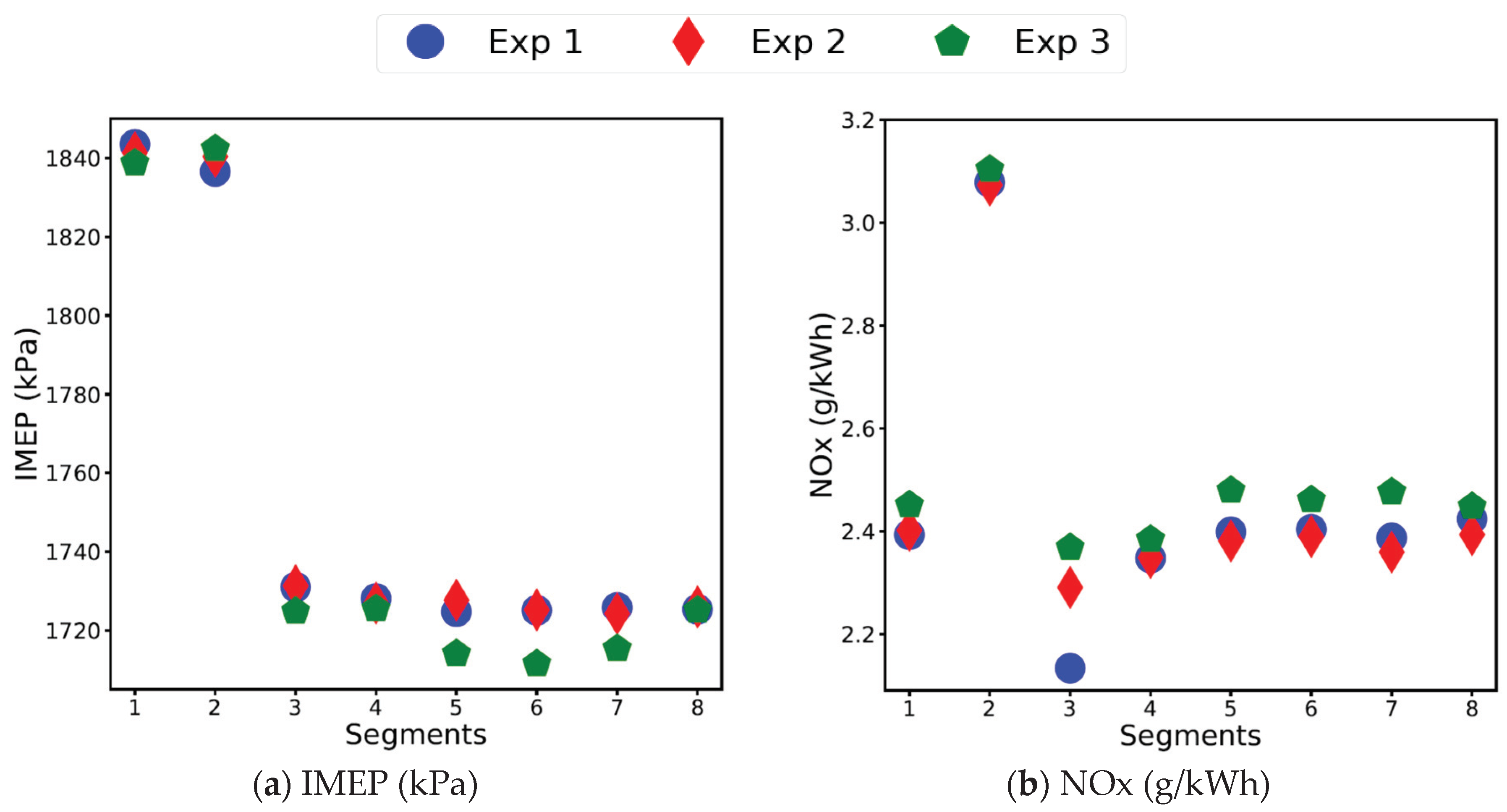
Each experiment was repeated three times to ensure repeatability and data integrity. Any possible variations in the three experimental sets (engine and emissions equipment) were further investigated through statistical measures, such as the mean, median, and standard deviation. The mean values of the indicated mean effective pressure (IMEP) and the NOx emissions from the PEMS, at 100% load, in all segments, at 2000 rpm in the three repeat experiments are shown in Figure 2a,b. Since the results obtained for the mean, median and mode of the other parameters for the three repeat experiments showed similar repeatability at both engine speeds, they are not included here. The repeatability of the experiments was found to be within ±3%. The higher variability in the NOx emissions shown in Segment 3 (Figure 2b) is attributable to subtle differences in the timing of the change in injection strategy during that segment.

3. Results and Discussion

This section analyses the effects of engine start during different stages of warm up on the performance and emissions of a diesel engine, over a custom designed cold and intermediate start drive cycle. The drive cycle was designed to facilitate discretising the engine warm up period into different stages of engine start (cold, intermediate, and hot start). As the custom drive cycle includes an engine stop/start period between the engine run segments, it ensured the discretisation of the engine run segments into various stages of engine warm up, based on the engine coolant and oil temperatures. This will be discussed in the first part of this section (Section 3.1), by analysing the engine coolant and oil temperatures at different stages. The second part of this section (Section 3.2), is a comparative analysis of engine performance parameters such as the indicated specific fuel consumption (ISFC), brake specific fuel consumption (BSFC), energy produced from combustion, IMEP, brake mean effective pressure (BMEP), friction mean effective pressure (FMEP), and exhaust temperature. Finally, in the last part of this section (Section 3.3), engine emissions such as NOx and HC emissions have been investigated.
The experimental data at each load in each segment, at both engine speeds, was analysed by calculating the mean of the data. Approximately 5 s of the data at the start of each load in each segment was excluded from the analysis because it was highly transient and unstable, owing to turbocharger lag. The turbocharger lag caused the engine to be highly transient during the first few seconds of each 30 s time period at each load in each segment. Since mean values were used in the analysis of the data at each load, the initial 5 s of data being highly transient and unstable would have caused a significant offset in the results. This was particularly critical while analysing the cold start emissions. The turbine rotor’s acceleration is a key contributor to the phenomenon of turbocharger lag, as the engine crank shaft and the turbine shaft are not mechanically connected to each other and hence are not in a synchronous rotation. The mismatch between the rotational speeds produces a subsequent lag in the turbocharger [22,35].
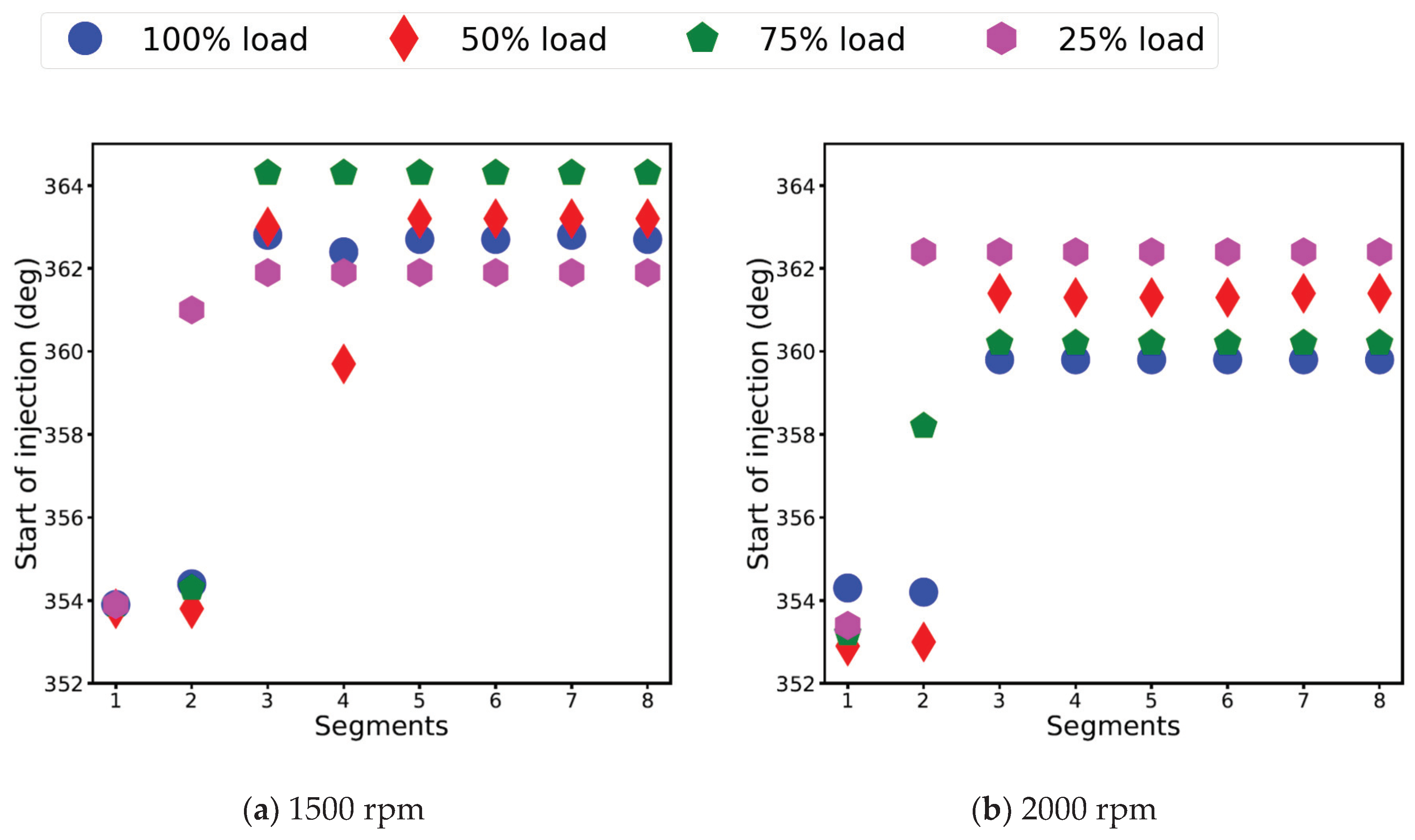
It was observed that due to the engine starting cold, the engine control unit (ECU) restricted the maximum engine load at 1500 rpm (engine speed for rated torque). The most likely reason for this strategy was to safeguard the engine from any potential failure. It was further observed that these engine restrictions were not applied at 2000 rpm (engine speed for rated power). It was also observed that the ECU followed an advanced injection strategy in Stage 1 (Segments 1 and 2) of the custom cycle, when the engine was cold, while by the end of Segment 2, when the coolant temperature reached 65 °C, the ECU switched to a retarded injection strategy at both engine speeds. The most likely reason for the advanced injection strategy during cold start (Segments 1 and 2) was to achieve higher in-cylinder pressure and temperatures to warm up the engine faster, while a retarded injection strategy in an intermediately warmed up engine was helpful in reducing NOx.

3.1. Engine Coolant and Oil Temperature

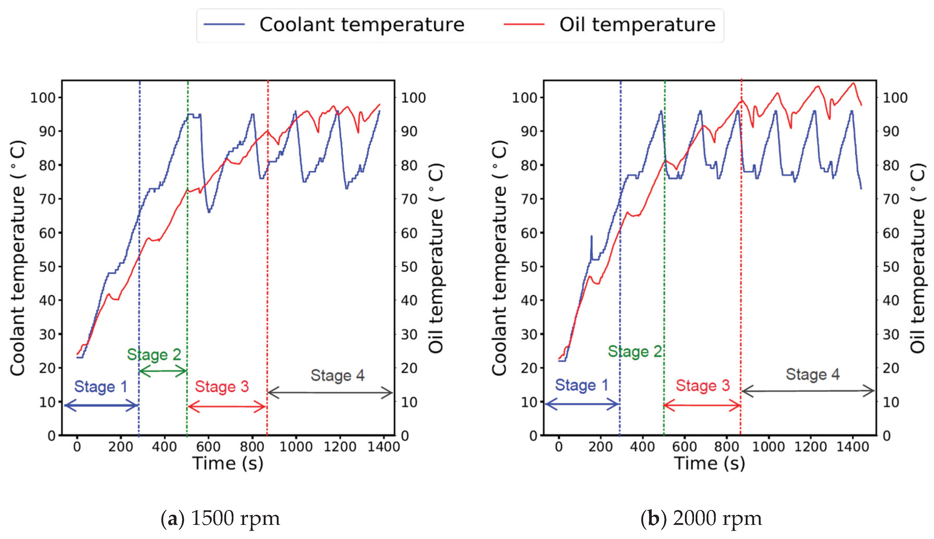
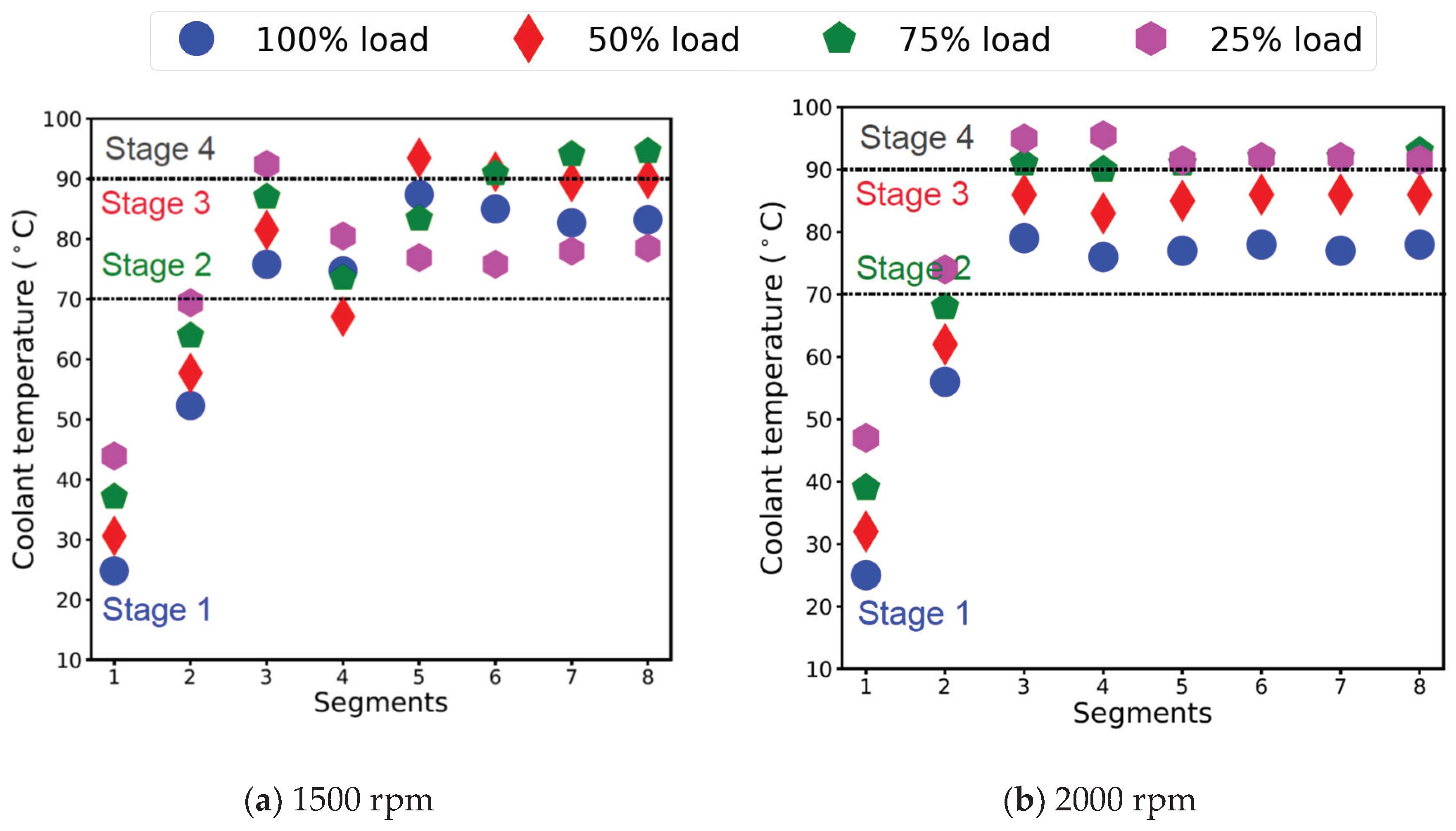
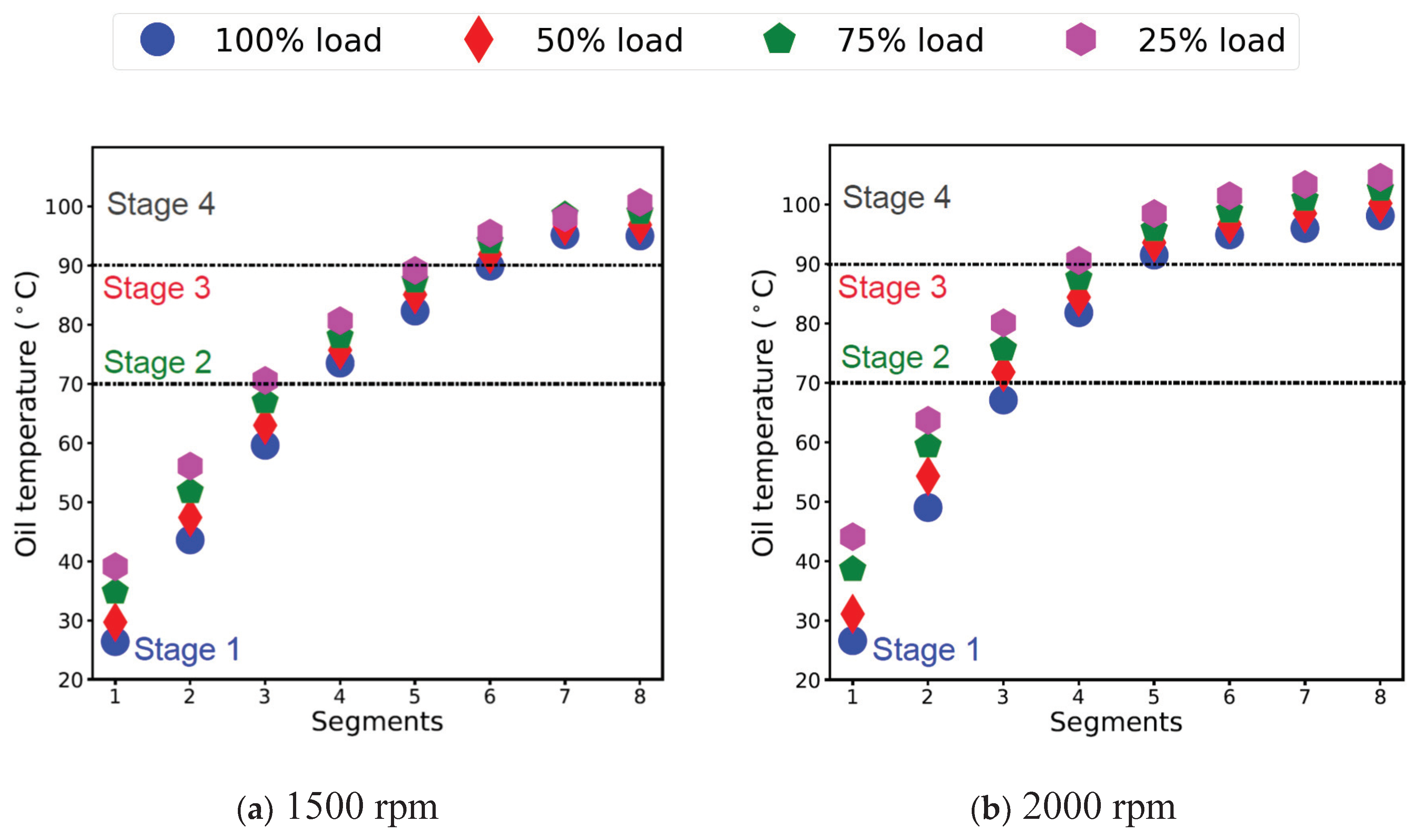
Based on the engine coolant and oil temperatures, shown in Figure 3, Figure 4 and Figure 5, the engine warm up in the current study can be divided into four stages, namely:
  • Stage 1—Engine cold start (coolant and oil < 70 °C);
  • Stage 2—Engine intermediate start—I (70 °C < coolant < 90 °C and oil < 70 °C);
  • Stage 3—Engine intermediate start—II (coolant > 90 °C and 70 °C < oil < 90 °C);
  • Stage 4—Engine hot start (coolant > 90 °C and oil > 90 °C).

3.1.1. Stage 1—Engine Cold Start (Coolant and Oil < 70 °C)

Stage 1 can be defined as ‘engine cold start period’, in which the engine coolant and oil temperatures were less than 70 °C. This period is called cold start because according to the EU commission 2012/46/EU [13], the cold start period ends when the engine coolant temperature reaches 70 °C. The temperature at the end of Segment 2 in Stage 1 was approximately 70 °C. The temperature increased approximately 5 °C during the engine stop period between Segments 2 and 3, due to continued heat transfer from the metal wall to the coolant, even when the coolant flow was stopped. Figure 3, Figure 4 and Figure 5 show that Stage 1 (engine cold start) occurred in Segments 1 and 2 of the custom cycle.

3.1.2. Stage 2—Engine Intermediate Start—I (70 °C < Coolant < 90 °C and Oil < 70 °C)

Stage 2 can be defined as the ‘engine intermediate start period—I’, in which the engine coolant temperature was between 70 °C and 90 °C and the oil temperature was less than 70 °C. In this stage, the coolant and oil temperatures continued to increase and therefore, the engine was not thermally stabilised. Figure 3, Figure 4 and Figure 5 show that Stage 2 (engine intermediate start—I) occurred in Segment 3 of the custom cycle.
Although the coolant temperature reached 95 °C, the oil temperature reached up to 70 °C at the end of Stage 2 (Segment 3), at both engine speeds. The thermostat opened and allowed the coolant to circulate through the radiator during the engine stop period at the end of Segment 3. The coolant temperature dropped to approximately 70 °C, with the opening of the thermostat and thereafter, it was cyclic. At the end of Stage 2, although the coolant temperature dropped due to the mixing of the fresh coolant from the radiator, there was no heat transfer from the oil to the cylinder wall (it was rather the opposite) and the oil temperature continued to rise, as shown in Figure 3 and Figure 5. This is indicative of the oil continuing to warm up and reaching approximately 90 °C in Segments 4 and 5 and Segment 4 at 1500 and 2000 rpm, respectively.

3.1.3. Stage 3—Engine Intermediate Start—II (Coolant > 90 °C and 70 °C < Oil < 90 °C)

Stage 3 can be defined as the ‘engine intermediate start—II’, in which the engine coolant temperature was greater than 90 °C, and the oil temperature was between 70 °C and 90 °C. In this stage, the engine coolant reached an optimal temperature, while the oil temperature continued to increase and therefore, the engine was still not thermally stable. The lubricating oil temperature reached approximately 90 °C, at the end of Segments 5 and 4 at 1500 and 2000 rpm, respectively. The oil warm up also followed the same trend as the coolant and it was observed to have warmed up faster at 2000 rpm, compared to 1500 rpm, due to the higher cumulative energy produced at 2000 rpm. Moreover, the oil temperature gradient experienced a lag of approximately 10 °C as compared to the coolant temperature. Figure 3, Figure 4 and Figure 5 show that Stage 3 (engine intermediate start—II) occurred in Segments 4 and 5 and Segment 4 of the custom cycle, at 1500 and 2000 rpm, respectively.
In the current experimental study, although the engine was considered to be warmed up when the coolant temperature reached 70 °C the engine performance did not stabilise, due to sub-optimal oil temperature. This has also been reported in the literature by [18,19]. This instability or inefficiency in the engine’s performance is characterised by higher friction losses, ineffective combustion, and an improper functional set up of after-treatment devices for reducing emissions, dissimilar to the steady state behaviour [18,36,37]. The effect of lag between the oil and coolant temperatures has been reported in studies such as [15,16,17]. The engine performance inefficiencies occurring in the intermediate warm up stage of the engine (Stages 2 and 3), due to the sub-optimal oil temperature has been a subject of interest in the current study. Further discussion on the effects of sub optimal oil temperature on friction can be found in Section 3.2.1.

3.1.4. Stage 4—Engine Hot Start (Coolant > 90 °C and Oil > 90 °C)

Stage 4 can be defined as the ‘engine hot start period’, in which both the engine coolant and oil temperatures were greater than 90 °C. In this stage the engine was considered to be thermally stable, operating at an optimal temperature. Figure 3, Figure 4 and Figure 5 show that Stage 4 (engine hot start) occurred from Segment 6.
Although the oil temperature reached greater than 90 °C at the end of Stage 3 at both engine speeds, the oil temperature continued to increase until 98 °C, before it dropped in Segments 8 and 7, due to the opening of the thermostat, at 1500 and 2000 rpm, respectively. Therefore, it was only in Segments 8 and 7 at 1500 and 2000 rpm, respectively, that the engine started to show heat transfer in one direction; from the oil to the cylinder wall on the gas side and from the cylinder wall to the coolant on the coolant side. It is therefore appropriate to consider the engine operation to be approaching steady state from warmed up, in Segments 8 and 7 at 1500 and 2000 rpm, respectively, where both the oil and coolant temperatures were observed to become cyclic, due the opening of the thermostat and all engine components were completely warmed up.

3.2. Engine Performance Parameters

3.2.1. Indicated Mean Effective Pressure (IMEP), Brake Mean Effective Pressure (BMEP), Friction Mean Effective Pressure (FMEP)

While the engine torque is a measure of the engine’s ability to do work, it depends on the engine size. Therefore, a more useful engine performance measure can be the IMEP, which is obtained by dividing the indicated work (IW) per cycle by the cylinder volume, as given in Equation (1) [6].
I M E P = I W V d   ( kPa )
where IW is the indicated work per cycle and Vd is the swept volume.
Typically, the indicated work done per cycle is determined by integrating across all four strokes of the engine and can be written as Equation (2):
I W =   p d V
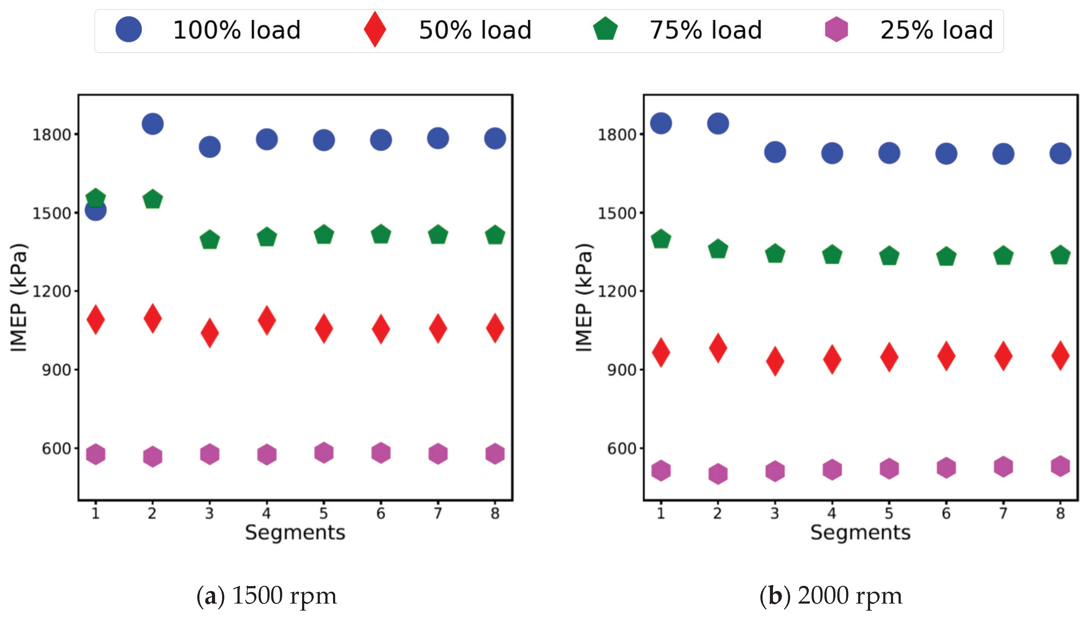
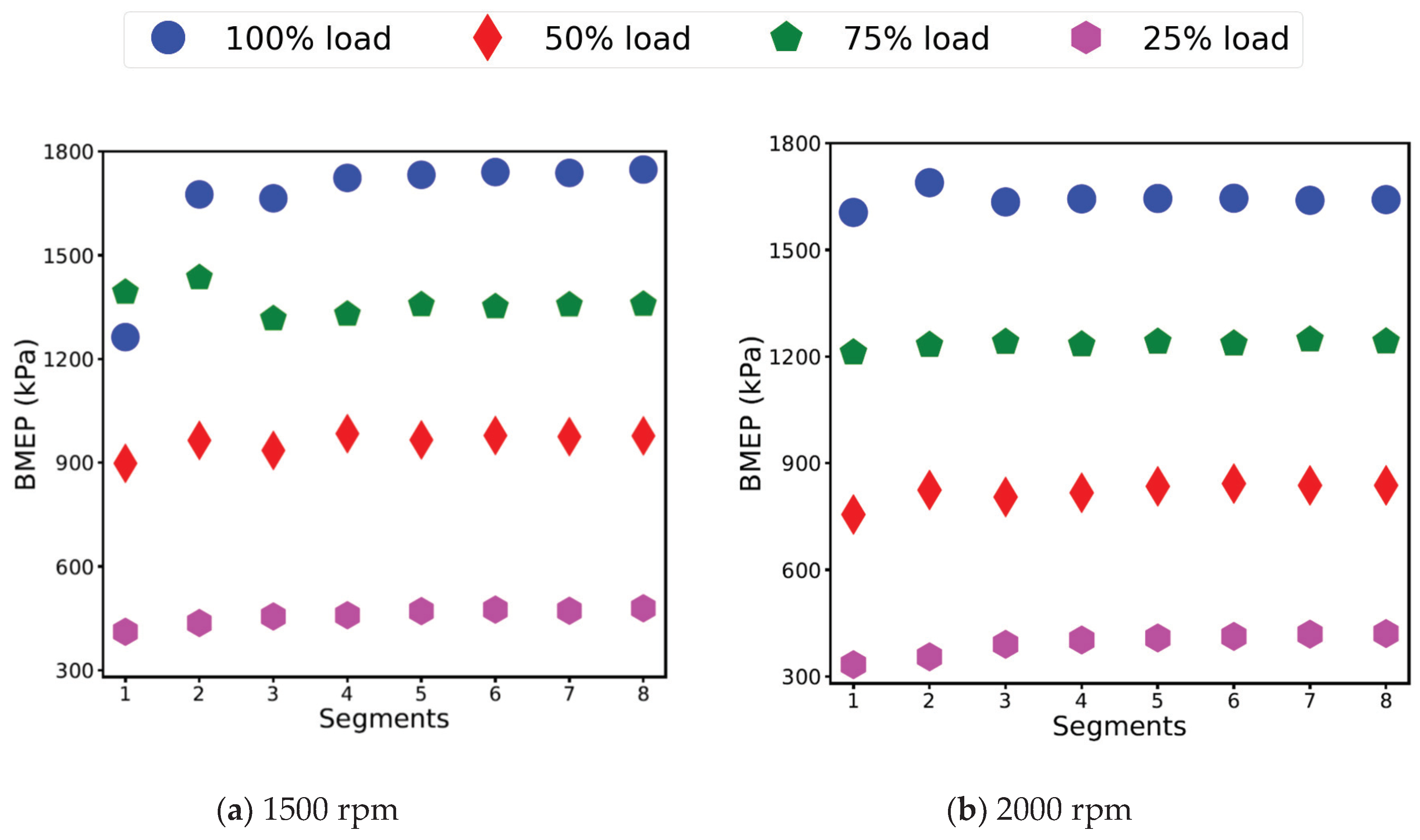
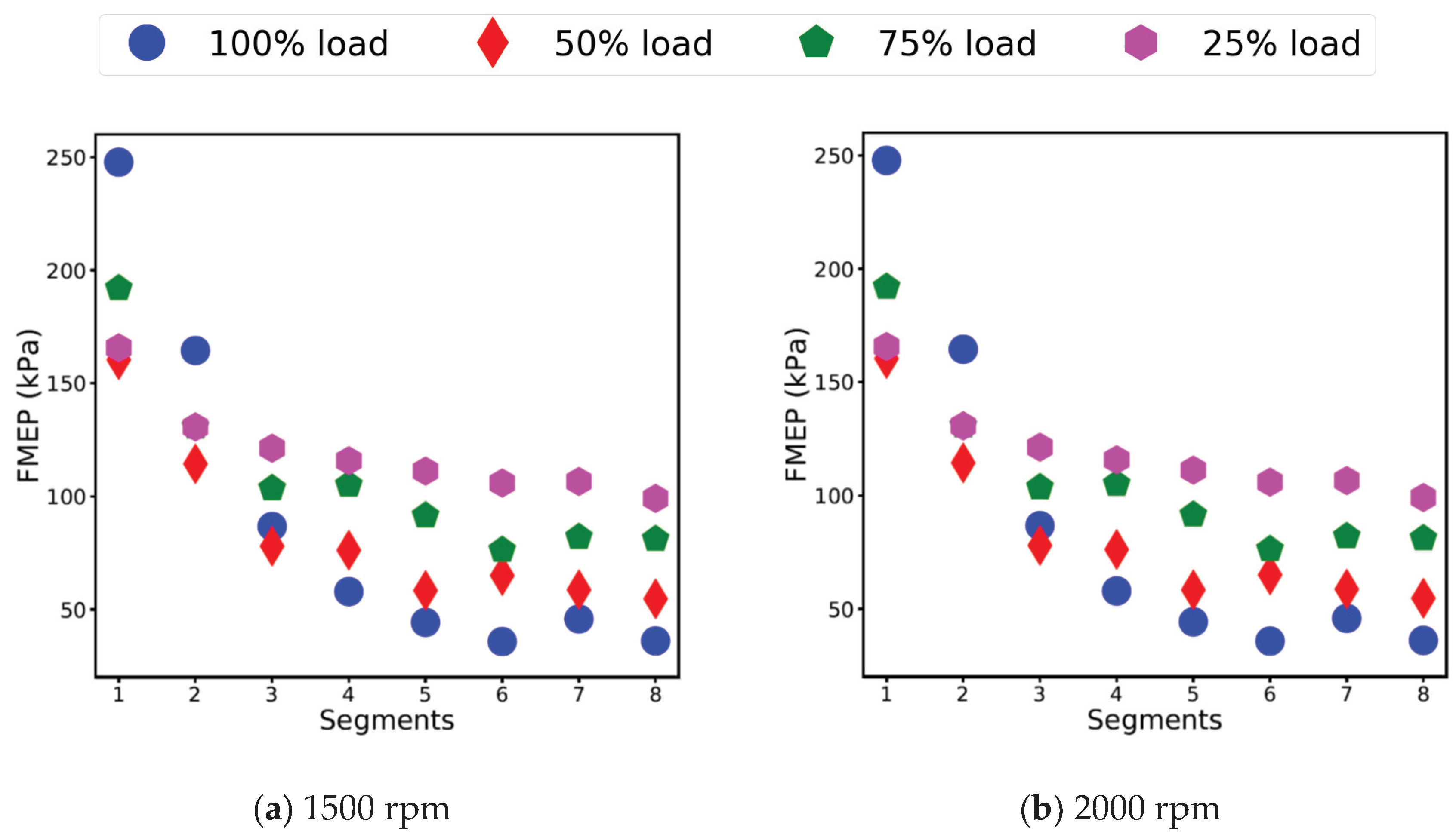
The FMEP is indicative of the mechanical work lost due to the friction generated from the moving components (friction losses), running the engine accessories (auxiliary losses) and pumping losses [6]. The FMEP is defined as the difference between the IMEP and BMEP, where the BMEP is calculated from the engine torque measured by the dynamometer. The influence of the different stages of engine warm up on the IMEP, BMEP, and FMEP are discussed in this section. Figure 6, Figure 7 and Figure 8 show the IMEP, BMEP, and FMEP values, respectively, at each load in all stages of the engine warm up in the custom cycle, at both engine speeds.
During Stage 1 (engine cold start—Segments 1 and 2), the mean values of the IMEP were observed to be the highest in Segment 1, due to increased friction during cold start. In Segment 2, as the coolant temperature increased and the friction was reduced, the BMEP was observed to increase by approximately 1% to 2%, while the IMEP varied within ±0.5% from Segments 1 to 2. It was also observed that the FMEP values showed a reduction of approximately 35% to 45% from Segments 1 to 2, when the coolant temperature increased from ranging approximately between 25 °C and 45 °C (Segment 1) to 50 °C to 60 °C (Segment 2). Due to the ECU restrictions applied in Segments 1 and 2 at 1500 rpm to achieve 100% load, the IMEP in Segment 1 at 1500 rpm recorded a lower value.
During Stage 2 (intermediate start—I—Segment 3), the IMEP and BMEP values decreased by approximately 2% to 3%. Although in this stage, the BSFC increased by approximately 3% to 7%, due to the retarded injection, the most likely reason for the decrease in the IMEP and BMEP could have been due to lower cylinder temperatures. Moreover, a reduction of approximately 60% in the FMEP from Segments 1 to 3 (Stage 1 to Stage 2) was observed.
During Stage 3 (intermediate start—II—Segments 4 and 5), as the engine coolant and oil temperatures reached greater than 90 °C in Segment 4, an increase in the IMEP and BMEP by approximately 4% to 8% was observed. Moreover, the largest reduction in FMEP was observed at 100% load, approximately 45% and 15% from Segment 3 to Segment 4 (Stage 2 to 3), at 1500 and 2000 rpm, respectively. The significant increase in the IMEP and BMEP (4% to 8%) in this stage indicate that these parameters are influenced by the engine temperature rather than the fuel consumption, because the BSFC was observed to have improved by only approximately 1% to 3% in this stage. During Stage 4 (engine hot start—Segments 6, 7, and 8), the IMEP and BMEP remained consistently varying between ±0.5% to ±1% (similar to the BSFC).
Moreover, it has been observed that at 25% load, the BMEP increased by approximately 15% and 20% at 1500 and 2000 rpm, respectively, from Segments 1 to 6 (Stage 1 to 4). The most likely reason for this significant improvement in the BMEP can be attributed to the high air-to-fuel ratio at 25% load, resulting in significant efficiency improvements [6,38].
The difference between the IMEP at each load was observed to be higher, while it was smaller at each load in FMEP, which is indicative of the friction being dependent more on the engine speed rather than the load. Moreover, the FMEP at 2000 rpm has been observed to be significantly higher than at 1500 rpm in all segments.
It was observed in Stages 2, 3, and 4 (Segment 3 and onwards) that the FMEP values were higher at lower loads (50% and 25% load), as friction power (FP) is a significantly large part of the indicated power (IP), which increases with a decrease in load, varying between 10% to 100% between 100% load and idle [6]. It has also been observed that the higher the load, the smaller the normalised FMEP (by IMEP), as shown in Figure 9a,b, which is indicative of the mechanical efficiency being higher at higher loads and it increased as the engine warmed up at all loads. This is also indicative of higher energy losses taking place at lower loads, however, the FMEP in Figure 8a,b show that the energy losses did not completely contribute to overcoming friction, as the difference in FMEP between each load was small. The higher energy losses at lower loads most likely contributed to the heating of the lubricating oil during Stages 2 and 3, while in Stage 4, when both the coolant and oil temperatures were greater than 90 °C, the energy loss could have been exhausted as heat through the coolant. Moreover, the improvements in the range of approximately 4% to 8% in the IMEP and BMEP observed in Stage 3, compared to 2% to 3% in Stage 2, also indicate that the oil temperature reaching greater than 90 °C had a greater influence on the performance improvement. Therefore, a faster warm up of the lubricating oil would play an important role in improving the BMEP, consequently improving the mechanical efficiency of the engine, and thus making the warm up time of the lubricating oil to be more critical than coolant in defining engine warm up. It is reported by [17,39] that the lubricating oil takes approximately 15 min to reach 90 °C, leading to higher friction losses, increased fuel consumption and inefficient performance during the sub-optimal temperature period.

3.2.2. Specific Fuel Consumption and Combustion Energy

A useful parameter to measure the engine’s performance is the specific fuel consumption (SFC), defined as the total fuel flow rate per unit power output [6]. The ISFC is defined as the total fuel flow rate per unit indicated power (IP) output, whereas the BSFC is defined as the total fuel flow rate per unit brake power (BP) output, as shown in Equation (3) [6].
I S F C = m ˙ I P   and   B S F C = m ˙ B P   ( kg / kWh )
where m ˙ is the mass flow rate of the fuel (kg/h), IP and BP are the indicated power and brake power, respectively (kW).
The rate of fuel energy (E) supplied, which can be released by combustion is given by the product of the mass flow rate of the fuel supplied to the engine per cycle and the lower heating value (LHV) of the fuel, as shown in Equation (4) [6].
E ˙ = m ˙ c x L H V   ( kJ / kWh )
where m ˙ c is the mass flow rate of the fuel per cycle (kg/kWh) and LHV is the lower heating value of the fuel (kJ/kg). The rate of fuel energy ( E ˙ ) in Equation (4) was integrated to calculate the total fuel energy (kJ) at each load in each segment. This section analyses the ISFC, BSFC, and the fuel energy released from combustion during the various stages of engine warm up.
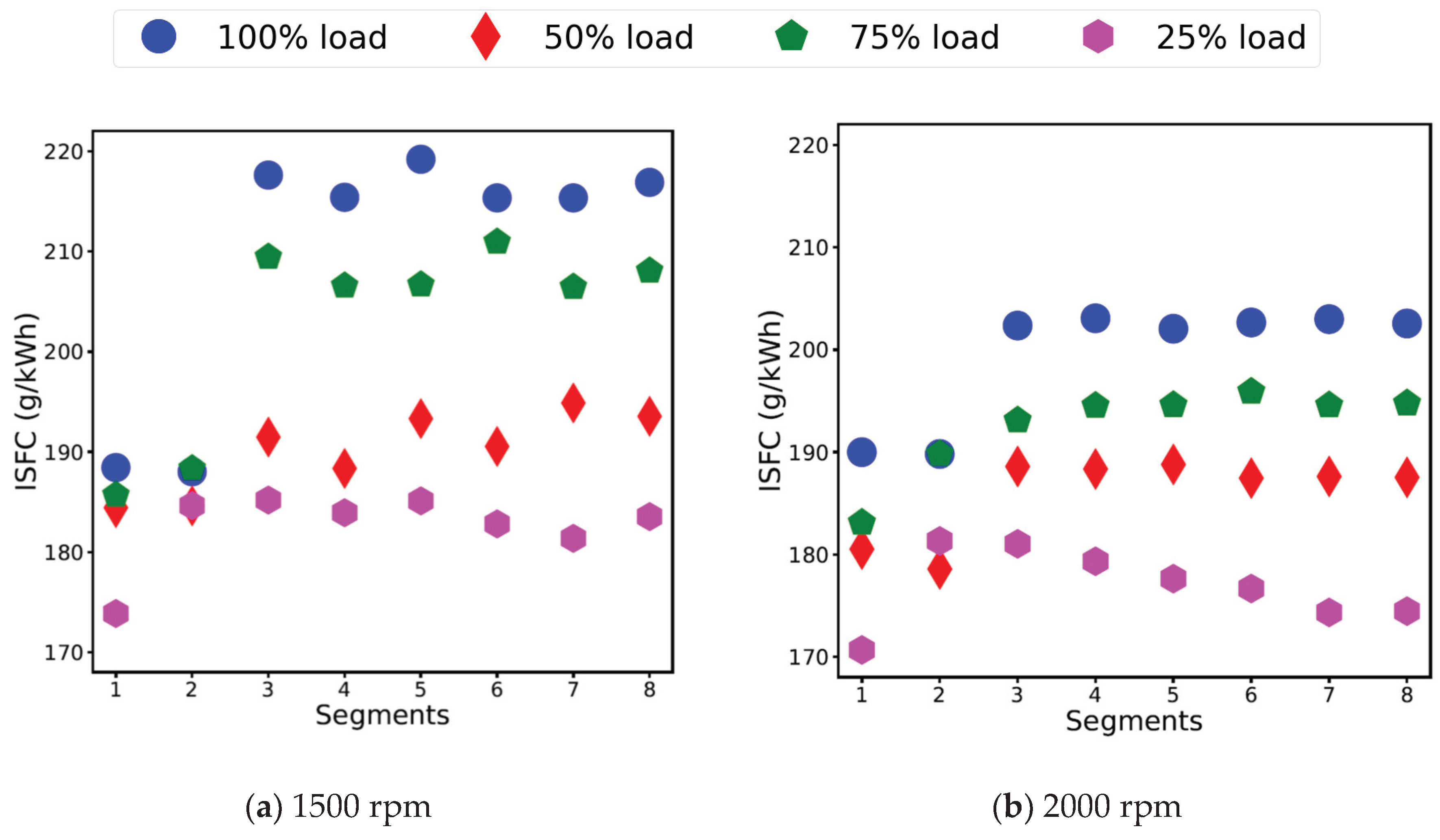
The influence of the different stages of engine warm up on the ISFC and BSFC are discussed in this section, shown in Figure 10 and Figure 11, respectively, at each load in all stages of engine warm up in the custom cycle, at both engine speeds. During Stage 1 (engine cold start—Segments 1 and 2), an improvement of approximately 1% in the ISFC and 2% to 10% in BSFC was observed from Segments 1 to 2, due to the increase in engine temperature from 25 °C to 45 °C in Segment 1 to 50 °C to 60 °C in Segment 2. It can be understood that lower values of ISFC during Stage 1 were due to higher friction (higher IP). It has also been observed that the fuel flow rate was restricted at 100% load in Segments 1 and 2 at 1500 rpm, however, they were not restricted at 2000 rpm. Increased BSFC during cold start has been reported by a number of studies in the literature, such as [7,22,40], as observed in this stage.
During Stage 2 (intermediate start—I—Segment 3), the injection was retarded (refer to Figure 12a,b), when the coolant temperature reached 70 °C, leading to an increase in the ISFC and BSFC by approximately 4% to 6% and 3% to 7%, respectively. The coolant temperature during this stage was greater than 70 °C, and therefore, it seems that the injection retard had a greater influence in increasing the BSFC, dominating over the effects of reduced friction and increased engine temperature, which would have tend to decrease BSFC.
A decrease in the ISFC and BSFC of approximately 0.5% to 1% and 1% to 3%, respectively, was observed from Stage 2 to 3 (Segments 3 to 4), which can be attributed to the increased coolant and oil temperature. During Stage 3 (intermediate start—II—Segments 4 and 5), the engine coolant and oil temperatures were greater than 90 °C and 70 °C, respectively, in Segment 4, while in Segment 5, the oil temperature also reached greater than 90 °C. Moreover, during this stage, the ISFC and BSFC varied approximately between ±2% and ±1%, respectively, when Segments 4 and 5 are compared.
During Stage 4 (engine hot start—Segments 6, 7 and 8), although the engine coolant and oil temperatures were greater than 90 °C and all the engine components were completely warmed up, the ISFC and BSFC varied approximately between ±2%, with higher variations observed at 1500 rpm. Similar variations of approximately ±2% were also observed between Stages 3 and 4 in the ISFC and BSFC, with higher variations observed at 1500 rpm, compared to 2000 rpm. The higher variations in the ISFC and BSFC at 1500 rpm could be attributed to a relatively more stable combustion at 2000 rpm, compared to 1500 rpm. Moreover, as the friction was reduced (IP decreased), the ISFC was observed to have increased by approximately 5% in Segment 8.
The ISFC has been observed to be higher in all stages at 1500 rpm, compared to 2000 rpm. The likely cause of that could be attributed to higher IP, due to higher friction at 2000 rpm, compared to 1500 rpm [6], (ISFC being inversely proportional to IP). It has been observed that there was a smaller difference between the ISFC and BSFC at higher loads (100% and 75% loads), while a higher difference was observed at lower loads (50% and 25% loads). This is because of the FMEP is largely related the engine speed, rather than the load, which is also indicative of a higher mechanical efficiency at higher loads, as also shown by the normalised FMEP in Figure 9a,b.
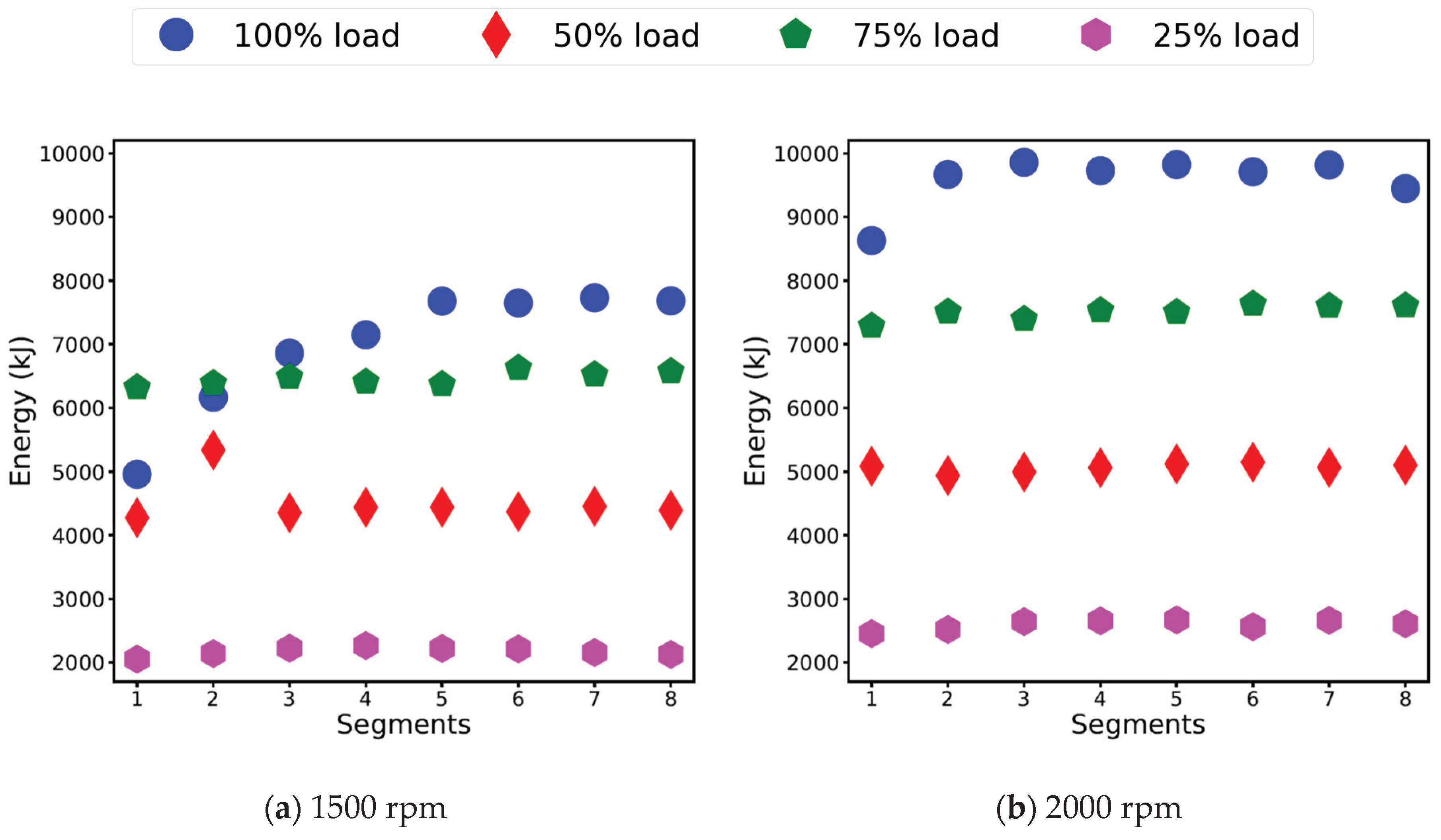
The cumulative energy released from the combustion of fuel was observed to be higher at 2000 rpm, as the BSFC at 2000 rpm was higher, compared to 1500 rpm, except at 100% load in all stages, where higher BSFC values were observed at 1500 rpm. However, due to the higher engine speed and higher number of cycles at 2000 rpm (12.5 cycles and 16.66 cycles in a second at 1500 and 2000 rpm, respectively), the cumulative energy produced from combustion was always higher at 2000 rpm compared to 1500 rpm. The mean values of the cumulative energy released from the combustion of fuel at each load in each segment, at 1500 and 2000 rpm, respectively, are shown in Figure 13a,b. The higher cumulative energy produced from combustion at 2000 rpm seemed to be responsible for the faster heating of the coolant at 2000 rpm, where the temperature at the end of Segment 2 at 2000 rpm was approximately 5 °C higher than at 1500 rpm, as shown in Figure 4a,b. The cumulative energy produced from the combustion is representative of the rise in the coolant temperature, with the energy transferred to the cylinder walls as heat, with more heat accumulated due to a higher number of cycles at any particular load at 2000 rpm, compared to 1500 rpm. Therefore, the BSFC and combustion energy are important engine performance parameters, which influence the engine warm up, rather than the operating conditions of speed and load alone [6].

3.2.3. Exhaust Temperature

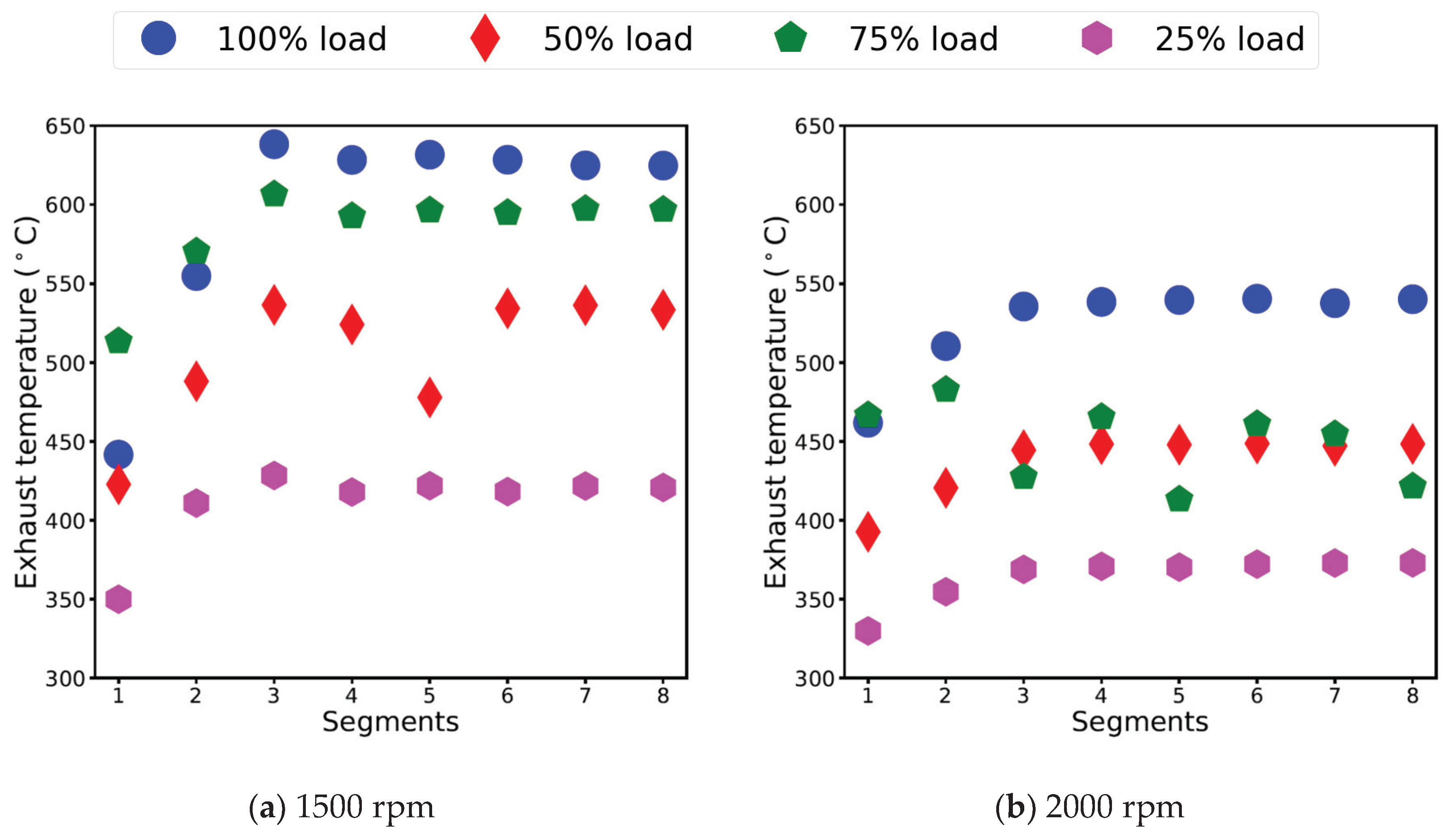
The influence of various stages of engine warm up on the exhaust temperature is discussed in this section. There are thermocouples where the exhaust manifolds of Cylinder 1–3 and Cylinder 4–6, respectively, merge. The exhaust temperature was calculated as an average of the temperatures measured by these. Figure 14a,b show the exhaust temperatures at each load in each stage of the custom cycle, at 1500 and 2000 rpm. During Stage 1 (engine cold start), the exhaust temperatures showed an increment of approximately 10% to 15% and 6% to 10%, from Segment 1 to Segment 2, with a higher percentage difference being observed at lower loads (50% and 25% loads) at both engine speeds, 1500 and 2000 rpm. Due to the ECU restrictions applied at 100% load in Segments 1 and 2, at 1500 rpm, the exhaust temperature in Segments 1 and 2 showed a difference of approximately 20%.
During Stage 2 (engine intermediate start—I), in Segment 3, the exhaust temperatures further increased by approximately 4% to 9% and 2% to 5%, at 1500 and 2000 rpm. The increment in the exhaust temperature in Stage 2 was an after effect of the higher temperatures produced in Segment 2 due to the advanced injection strategy followed in Stage 1 (Segment 1 and 2). The engine switched to a retarded injection strategy in Stage 2, due to which the cylinder temperatures were lowered and the effects of which were observed later in Stage 3 (Segments 4 and onwards). During Stages 3 and 4 (intermediate start—II and hot start), in Segments 4 and onwards, the exhaust temperatures remained approximately consistent within ±1%.
The exhaust temperatures at all loads at 1500 rpm were observed to be higher than 2000 rpm, as 1500 rpm was the engine speed for rated torque. However, the exception was at 100% load in Segment 1, due to the engine restrictions applied at 1500 rpm. Moreover, it has been observed that at 75% load at 2000 rpm, the exhaust temperature decreased in Segments 3 and onwards. The most likely reason for this could be due to an unusual combustion phenomenon taking place at this load, such as retarded injection complemented with a longer combustion duration. This could have caused the combustion to finish late in the expansion stroke, thereby causing more fuel to burn in the diffusion combustion phase and releasing less heat, consequently leading to lower exhaust temperatures.

3.3. Engine Exhaust Emissions

3.3.1. NOx Emissions

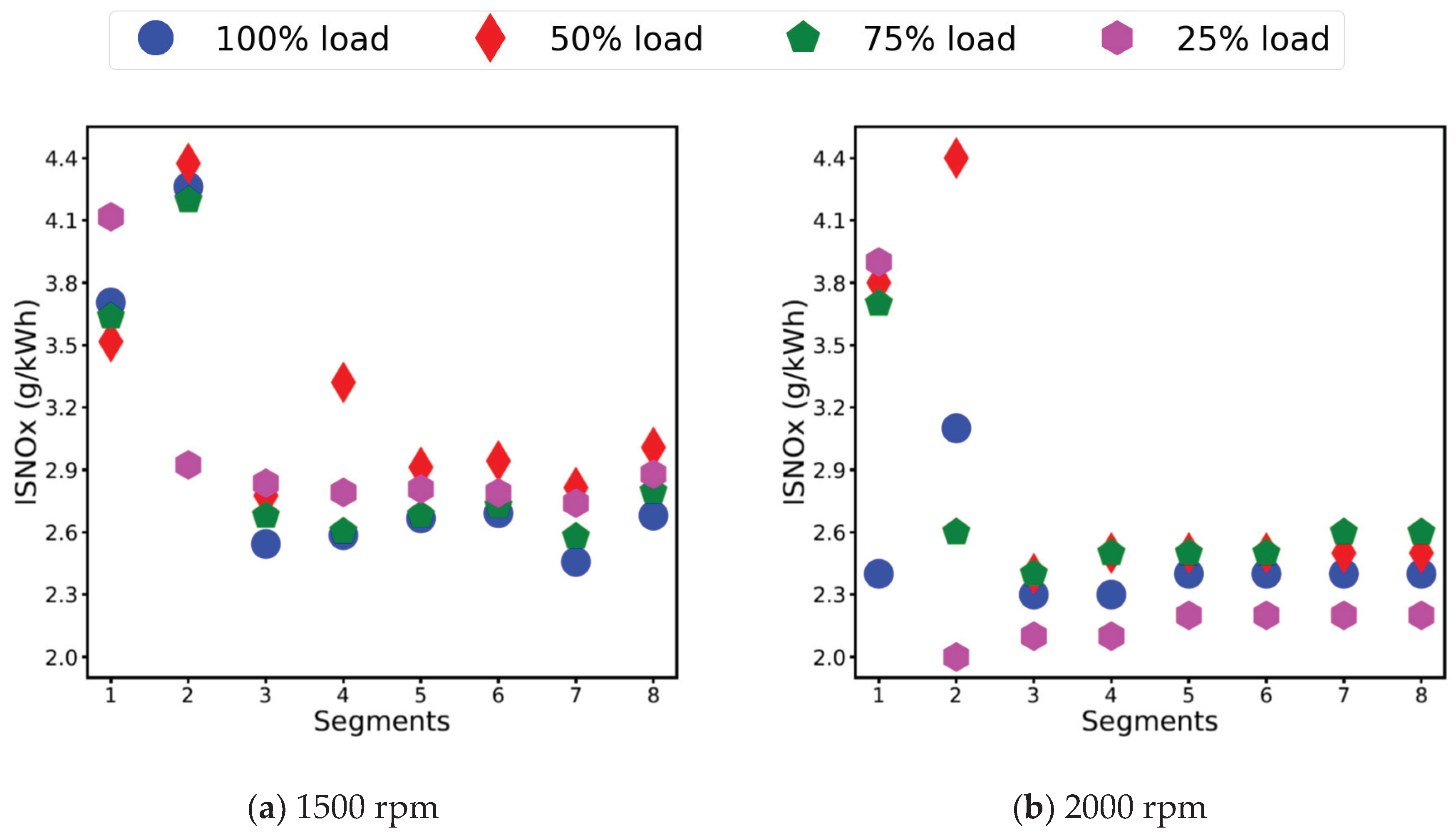
NOx consists of nitrogen monoxide (NO) and nitrogen dioxide (NO2) [35]. NOx is highly dependent on the combustion temperature (primary dependence), local concentration of oxygen and the combustion duration [6,35,38]. Therefore, as the combustion temperature increases, the NOx emissions increase [21]. When the injection is advanced, a large percentage of the combustion occurs in the premixed stage, which increases the NOx formation [35,38]. However, as the injection is retarded, it reduces the cylinder temperature as combustion occurs late, thereby reducing NOx [6,21,38]. In the current study, the PEMS instrument measures all of the oxides of nitrogen (NO, NO2 and N2O) without differentiating between them, the indicated specific NOx (ISNOx) values reported here are therefore a measure of all of the oxides of nitrogen. The reason indicated specific (rather than brake specific) emissions are used in this study was to ensure that the results were tied to combustion rather than mechanical friction, particularly during cold start where the friction losses are significant, as seen in Section 3.2.1. Figure 15a,b show the ISNOx emissions at each load in all stages of the engine warm up in the custom cycle.
During Stage 1, in Segments 1 and 2, the ISNOx emissions were high due to the advance injection strategy used during the cold start, which has been shown to increase the ISNOx and particle emissions [6,34,37,40,41]. However, as the engine coolant temperature increased to approximately 50 °C to 60 °C in Segment 2 from 25 °C to 45 °C in Segment 1, the ISNOx emissions increased further by approximately 15% to 30%. During Stage 2, in Segment 3, when the coolant temperature reached greater than 70 °C and the injection was retarded, the ISNOx emissions decreased by approximately 30% to 40% and 25% to 45%, at 1500 and 2000 rpm, respectively. During Stage 3, in Segments 4 and 5, an increase of approximately 4% to 5% in ISNOx emissions was observed, as the coolant temperature reached greater than 90 °C and the oil temperature was between 70 °C and 90 °C. During Stage 4, in Segments 6, 7, and 8, when both the coolant and oil temperatures were greater than 90 °C, with all engine components completely warmed up, the ISNOx became stable and varied between ±2%.
In the current study, the advanced injection strategy led to higher combustion temperatures and an increase in engine coolant temperature in Stage 1, which led to decreased BSFC by approximately 2% to 10%. It is reported in the literature that the ISNOx increases due to an increase in temperature [21] and decreases with a decrease in fuel consumption [8]. However, the effects of higher combustion temperature seem to be more pronounced than that of lower BSFC, as an increase of approximately 15% to 30% ISNOx emissions were observed in Stage 1 (from Segments 1 to 2), due to the high in-cylinder temperatures produced [6,21]. Therefore, the advanced injection strategy, which was successful in achieving a faster warm up and reducing fuel consumption in Segments 1 and 2, resulted in increased ISNOx emissions.
It was also observed that the ISNOx in Stage 1 increased as the engine run segment progressed from one load to another, with the maximum values observed in the last load (25%) of Segment 1. The most likely cause of this could be attributed to the temperature increase from the start to the end of Segment 1 (100% to 25% load in the 120 s of the engine run segment). Therefore, it seems that in Stage 1, while the engine was cold, the temperature generally had more influence on the ISNOx rather than the load or fuel consumption.
Although the ISNOx emissions were approximately similar in Stage 1, when comparing the 1500 and 2000 rpm cases, the ISNOx emissions were observed to be approximately 10% to 20% higher at 1500 rpm compared to 2000 rpm in Stages 2, 3, and 4 (Segment 3 and onwards). This could be due to the higher combustion temperatures produced at 1500 rpm, which is also evident from the higher exhaust temperatures at 1500 rpm, consequently producing higher NOx [6,8,35,38].
It has been observed that the raw NOx emissions (g/s) decreased with a decrease in load, at both engine speeds, as reported in the literature [21,35]. However, the ISNOx emissions (g/kWh) have been observed to increase with decreasing loads, in Stages 2, 3, and 4 (Segments 3 and onwards), with the only exception to the trend at 25% load at 2000 rpm, where the ISNOx emissions were the lowest amongst all loads, which could have been due to the unusual combustion taking place at low load at 2000 rpm, such as longer combustion duration, with retarded injection, producing a comparatively lower in-cylinder temperature, leading to lower ISNOx.
It has been observed that the ISNOx emissions were higher at 50% load, at both engine speeds, with the magnitude of increase being more prominent at 1500 rpm compared to 2000 rpm. The reason for this could have been related to combustion deterioration at lower loads (50% and 25% loads), due to the ignition retard in Stage 2 of engine warm up. As the combustion would deteriorate, the ECU might decrease the combustion duration to cause more fuel to burn in the premixed combustion stage, to have rapid heat release rates, leading to higher in-cylinder temperature and higher NOx.

3.3.2. Hydrocarbon Emissions

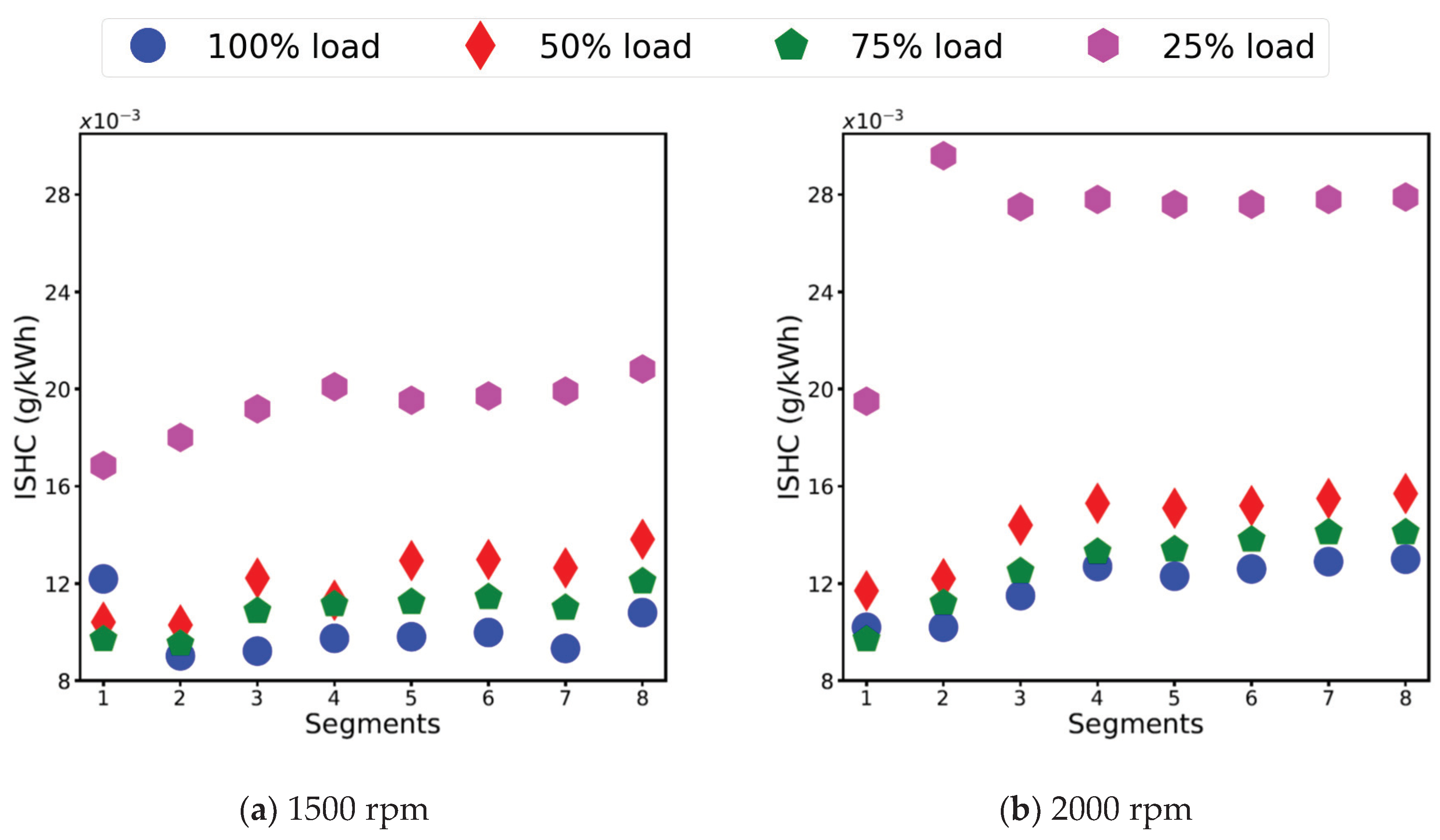
HC emissions in diesel engines, consisting of decomposed fuel molecules, as a consequence of incomplete combustion of the hydrocarbon fuel, are a useful measure of the combustion efficiency [6]. In a diesel engine, the heterogeneous mixture consist of pockets of rich (producing HC due to incomplete combustion) and lean mixtures (producing HC due to too lean to auto-ignite), becoming the primary source of unburned HC emissions. However, sources such as lubricating oil (especially when cold), cylinder crevices, and the fuel nozzle sac (which leaves the injector nozzle at low speed, late in the combustion process) also become secondary sources of unburned HC emissions [6,35,38]. Generally, engine idling and low load operation and a sudden load demand, produce high HC emissions [6,38]. Similarly, advancing the injection reduces HC emissions, with a NOx and particle emissions penalty, while retarding the injection increases HC emissions [6,38]. In the current study, the mean values of the indicated specific hydrocarbon (ISHC) emissions in (g/kWh) at each load were used to analyse the effects of the various stages of engine warm up on ISHC emissions. Figure 16a,b show the ISHC emissions at each load in all stages in the custom cycle at 1500 and 2000 rpm.
During Stage 1, in Segments 1 and 2, the ISHC emissions were higher due to the cold cylinder. A reduction in the ISHC emissions of approximately 2% to 7% was observed from Segments 1 to 2, as the engine temperature increased to approximately 50 °C to 60 °C in Segment 2 from approximately 25 °C to 45 °C in Segment 1. The cylinder temperature being low during Stage 1 could have hindered the atomisation of the vapourised fuel, resulting in the incomplete combustion of the fuel and consequently higher HC emissions. Moreover, the ECU employed an advanced injection strategy during Stage 1 to heat up the engine faster. This strategy could have been helpful in reducing the ISHC emissions, however, it led to increased NOx, as discussed in Section 3.3.1 and has also been shown in other studies, such as [6,35,38,41,42].
During Stage 2, in Segment 3, the ISHC emissions increased by approximately 12% to 18%, at each load, due to the engine switching to a retarded injection strategy, when the coolant temperature reached 65 °C. Moreover, an exceptional increase in the ISHC of approximately 50% was observed at 25% load at 2000 rpm, which could be an effect of deteriorated combustion at lower load [6]. Although the combustion process settled, as the engine was intermediately warmed up in Stage 2, the BSFC increased by approximately 3% to 7%, with a retarded injection, consequently leading to an increase in the ISHC emissions in this Stage.
During Stage 3, in Segments 4 and 5, the ISHC emissions have been observed to increase by approximately 6% to 10%. Although the engine warm up improved in this stage, with the engine coolant temperature greater than 90 °C and the oil temperature between 70 °C and 90 °C, the increase in the ISHC emissions could have been due to the increase in the BSFC by approximately 1% to 3% in this stage.
During Stage 4, in Segment 6, 7, and 8, the ISHC emissions have been observed to increase by approximately by 3% to 7%. Although, the engine was completely warmed up in this stage, with both the coolant and oil temperatures greater than 90 °C, the increase in the ISHC emissions can be attributed to two main reasons: firstly, it could have been due to the change in the crevice volume with the engine warm up [6]; and secondly, it could have been due to the presence of lubricating oil on the piston and combustion chamber walls, causing the ISHC emissions to increase [6].
It has been observed in the current experimental study that the ISHC emissions increased with a decrease in load, in all stages of engine warm up (cold, intermediate—I and II and hot start). The most likely reason for the increase in the ISHC emissions at lower load (50% and 25% load) could have been due to the combustion deterioration, in spite of leaner mixtures used at lower loads [6,38]. Figure 17a,b show the fuel-to-air equivalence ratio, at each load in each segment, at 1500 and 2000 rpm. The fuel-to-air equivalence ratio was calculated as the ratio of actual fuel-to-air and the stoichiometric fuel-to-air ratio. The actual fuel-to-air ratio was calculated by the experimentally measured fuel and air data. It has also been observed that the ISHC emissions at 2000 rpm were higher compared to 1500 rpm at all loads, due to higher fuel consumption at 2000 rpm [8]. It has also been observed that the increase in ISHC emissions at 25% load was more significant at 2000 rpm, compared to 1500 rpm. This could have also been an effect of deteriorated combustion [6], which could have been due to combustion occurring later in the expansion process [6,35,38].
A higher fuel-to-air equivalence ratio indicates higher ISFC at 1500 rpm, compared to 2000 rpm, as shown in Figure 17a,b, which has been discussed in the Section 3.2.2.

4. Conclusions

The current study offers a detailed analysis of engine performance and emissions in a heavy duty diesel engine during cold, intermediate, and hot start operation. The experiments were performed over a custom designed drive cycle, which consisted of eight engine run segments of 120 s each, having abrupt load changes within the segment and an engine stop period of 60 s between each segment. The current study was conducted to highlight the performance inefficiencies during the intermediate start stage, which was observed to be longer than the cold start stage. Listed below are the main conclusions of the current study:
  • The BSFC, NOx, and HC emissions were primarily influenced by the injection strategy.
  • The IMEP, BMEP, and FMEP were primarily dependent on the engine coolant and oil temperature and only showed improvements in Stage 3, when the oil temperature neared normal operating temperature.
  • The intermediate start stages (Stages 2 and 3) were found to be as critical as the cold start (Stage 1).
  • The advanced injection strategy during cold start was helpful in generating higher in-cylinder pressure and temperatures and thus achieving a faster warm up of the engine.
  • While switching to a retarded injection strategy aided in keeping the in-cylinder temperatures and pressure within the allowable range of the engine design, it also reduced the NOx emissions and led to increased BSFC and HC emissions.
  • The higher the load, the smaller the normalised FMEP (by IMEP), which indicated higher mechanical efficiency at higher loads and the energy lost at lower load most likely being utilised to heat up the oil during the intermediate warm up stage.
  • A decrease in NOx and an increase in HC emissions with an increase in ISFC at 25% load at 2000 rpm occurred in Stage 2 and onwards, which is understood to have been caused by combustion deterioration at lower loads at 2000 rpm.

Author Contributions

Conceptualization, F.L. and R.J.B.; Formal analysis, F.L. and T.B.; Investigation, F.L., A.Z., P.A., M.J., Z.R. and R.J.B.; Methodology, F.L., A.Z., P.A., S.S., Z.R., R.J.B. and T.B.; Project administration, S.S. and T.B.; Supervision, T.B.; Writing—original draft, F.L.; Writing—review & editing, T.B. All authors have read and agreed to the published version of the manuscript.

Funding

This work was jointly funded by the School of Engineering at Deakin University and the Biofuel Engine Research Facility at Queensland University of Technology.

Acknowledgments

The authors would like to express their gratitude to Amir Moghaddam, Aaron Venn and Matthew Klaassen, the laboratory technical staff in the BERF at QUT for their immense support with conducting the experiments. The authors would like to acknowledge and express gratefulness to Caltex for donating the required diesel to run this experimental campaign.

Conflicts of Interest

The authors declare no conflict of interest.

References

  1. Arumugam Sakunthalai, R.; Xu, H.; Liu, D.; Tian, J.; Wyszynski, M.; Piaszyk, J. Impact of Cold Ambient Conditions on Cold Start and Idle Emissions From Diesel Engines; SAE Technical Paper 2014-01-2715; SAE: Warrendale, PA, USA, 2014. [Google Scholar]
  2. Bielaczyc, P.; Merkisz, J.; Pielecha, J. A Method of Reducing the Exhaust Emissions from Di Diesel Engines by the Introduction of a Fuel Cut Off System During Cold Start; SAE Technical Paper 2001-01-3283; SAE: Warrendale, PA, USA, 2001. [Google Scholar]
  3. Hilliard, J.C.; Springer, G.S. Fuel Economy: In Road Vehicles Powered by Spark Ignition Engines; Springer Science & Business Media: New York, NY, USA, 2013; ISBN 1489922776. [Google Scholar]
  4. Reiter, M.S.; Kockelman, K.M. The Problem of Cold Starts: A Closer Look at Mobile Source Emissions Levels. Transp. Res. Part D Transp. Environ. 2016, 43, 123–132. [Google Scholar] [CrossRef] [Green Version]
  5. André, M. In Actual Use Car Testing: 70,000 Kilometers and 10,000 Trips by 55 French Cars under Real Conditions; SAE Technical Paper 910039; SAE: Warrendale, PA, USA, 1991. [Google Scholar]
  6. Heywood, J.B. Internal Combustion Engine Fundamentals; Automotive Technology Series; McGraw-Hill Book Company: Singapore, 1988; ISBN 9 780071 004992. [Google Scholar]
  7. Will, F. A Novel Exhaust Heat Recovery System to Reduce Fuel Consumption. In Proceedings of the 2010 World Automotive Congress, London, UK, 30 June–2 July 2010; pp. 1–10. [Google Scholar]
  8. Zare, A.; Nabi, M.N.; Bodisco, T.A.; Hossain, F.M.; Rahman, M.; Van, T.C.; Ristovski, Z.D.; Brown, R.J. Diesel Engine Emissions With Oxygenated Fuels: A Comparative Study Into Cold-Start And Hot-Start Operation. J. Clean. Prod. 2017, 162, 997–1008. [Google Scholar] [CrossRef] [Green Version]
  9. Suarez-Bertoa, R.; Astorga, C. Impact of cold temperature on Euro 6 passenger car emissions. Environ. Pollut. 2018, 234, 318–329. [Google Scholar] [CrossRef] [PubMed]
  10. Mendoza-Villafuerte, P.; Suarez-Bertoa, R.; Giechaskiel, B.; Riccobono, F.; Bulgheroni, C.; Astorga, C.; Perujo, A. NOx, NH3, N2O and PN real driving emissions from a Euro VI heavy-duty vehicle. Impact of regulatory on-road test conditions on emissions. Sci. Total Environ. 2017, 609, 546–555. [Google Scholar] [CrossRef]
  11. Ramadhas, A.S.; Xu, H.; Liu, D.; Tian, J.J. Reducing cold start emissions from automotive diesel engine at cold ambient temperatures. Aerosol Air Qual. Res. 2016, 16, 3330–3337. [Google Scholar] [CrossRef] [Green Version]
  12. Schauer, J.J.; Kleeman, M.J.; Cass, G.R.; Simoneit, B.R. Measurement of emissions from air pollution sources. 5. C1–C32 organic compounds from gasoline-powered motor vehicles. Environ. Sci. Technol. 2002, 36, 1169–1180. [Google Scholar] [CrossRef]
  13. Directive, E.U.C. Commission Directive 2012/46/EU Official Journal of the European Union. 2012. Available online: https://eur-lex.europa.eu/LexUriServ/LexUriServ.do?uri=OJ:L:2012:353:0080:0127:EN:PDF (accessed on 12 September 2019).
  14. Agency, E.P. Federal Test Procedure Review Project: Preliminary Technical Report EPA 420-R-93-007; US printing office: Washington, DC, USA, 1993. [Google Scholar]
  15. Jarrier, L.C.; Yu, J.C.; Gentile, R.D. Warm-Up of a D.I. Diesel Engine: Experiment and Modeling; SAE Technical Paper 2000-01-0299; SAE: Warrendale, PA, USA, 2000. [Google Scholar]
  16. Roberts, A.; Brooks, R.; Shipway, P. Internal Combustion Engine Cold-Start Efficiency: A Review of the Problem, Causes and Potential Solutions. Energy Convers. Manag. 2014, 82, 327–350. [Google Scholar] [CrossRef] [Green Version]
  17. Andrews, G.E.; Ounzain, A.M.; Li, H.; Bell, M.; Tate, J.; Ropkins, K. The Use of A Water/Lube Oil Heat Exchanger and Enhanced Cooling Water Heating to Increase Water and Lube Oil Heating Rates in Passenger Cars for Reduced Fuel Consumption and Co2 Emissions During Cold Start; SAE Technical Paper 2007-01-2067; SAE: Warrendale, PA, USA, 2007. [Google Scholar]
  18. Daniels, C.C.; Braun, M.J. The friction behavior of individual components of a spark-ignition engine during warm-up. Tribol. Trans. 2006, 49, 166–173. [Google Scholar] [CrossRef]
  19. Vittorini, D.; Di Battista, D.; Cipollone, R. Engine oil warm-up through heat recovery on exhaust gases—Emissions reduction assessment during homologation cycles. Therm. Sci. Eng. Prog. 2018, 5, 412–421. [Google Scholar] [CrossRef]
  20. Jiaqiang, E.; Liu, G.; Zhang, Z.; Han, D.; Chen, J.; Wei, K.; Gong, J.; Yin, Z. Effect analysis on cold starting performance enhancement of a diesel engine fueled with biodiesel fuel based on an improved thermodynamic model. Appl. Energy 2019, 243, 321–335. [Google Scholar]
  21. Giakoumis, E.G.; Rakopoulos, C.D.; Dimaratos, A.M.; Rakopoulos, D.C. Exhaust emissions of diesel engines operating under transient conditions with biodiesel fuel blends. Prog. Energy Combust. Sci. 2012, 38, 691–715. [Google Scholar] [CrossRef]
  22. Zare, A.; Bodisco, T.A.; Nabi, M.N.; Hossain, F.M.; Ristovski, Z.D.; Brown, R.J. A comparative investigation into cold-start and hot-start operation of diesel engine performance with oxygenated fuels during transient and steady-state operation. Fuel 2018, 228, 390–404. [Google Scholar] [CrossRef]
  23. Institute of Energy Research. Fossil Fuels. 2016. Available online: https://www.instituteforenergyresearch.org/?encyclopedia=fossil-fuels (accessed on 20 November 2019).
  24. Government of Australia. Vehicle Emissions Standards (Department of Infrastructure). 2018. Available online: https://www.infrastructure.gov.au/vehicles/environment/emission/index.aspx (accessed on 30 January 2020).
  25. DieselNet. Worldwide Harmonized Light Vehicles Test Cycle (WLTC). 2019. Available online: https://www.dieselnet.com/standards/cycles/wltp.php (accessed on 30 June 2019).
  26. Dimaratos, A.; Tsokolis, D.; Fontaras, G.; Tsiakmakis, S.; Ciuffo, B.; Samaras, Z. Comparative evaluation of the effect of various technologies on light-duty vehicle CO2 emissions over NEDC and WLTP. Transp. Res. Procedia 2016, 14, 3169–3178. [Google Scholar] [CrossRef] [Green Version]
  27. Gao, J.; Tian, G.; Sorniotti, A.; Karci, A.E.; Di Palo, R. Review of thermal management of catalytic converters to decrease engine emissions during cold start and warm up. Appl. Therm. Eng. 2019, 147, 177–187. [Google Scholar] [CrossRef]
  28. Trapy, J.D.; Damiral, P. An Investigation of Lubricating System Warm-Up for the Improvement of Cold Start Efficiency and Emissions of SI Automotive Engines; SAE Technical Paper 902089; SAE: Warrendale, PA, USA, 1990. [Google Scholar]
  29. Henein, N.A.; Zahdeh, A.R.; Yassine, M.K.; Bryzik, W. Diesel Engine Cold Starting: Combustion Instability; SAE Technical Paper 920005; SAE: Warrendale, PA, USA, 1992. [Google Scholar]
  30. Henein, N.A. Autoignition and Combustion in Diesel Engines under Cold Starting Conditions; Wayne State University Detroit MI Centre for Automotive Research; U.S. Army Research Office: Durham, NC, USA, 1997. [Google Scholar]
  31. Desantes, J.M.; García-Oliver, J.M.; Pastor, J.M.; Ramírez-Hernández, J.G. Influence of nozzle geometry on ignition and combustion for high-speed direct injection diesel engines under cold start conditions. Fuel 2011, 90, 3359–3368. [Google Scholar] [CrossRef] [Green Version]
  32. DieselNet. Federal Test Procedure (FTP). 2019. Available online: https://dieselnet.com/standards/cycles/ftp75.php (accessed on 20 February 2020).
  33. Bodisco, T.; Brown, R.J. Inter-cycle variability of in-cylinder pressure parameters in an ethanol fumigated common rail diesel engine. Energy 2013, 52, 55–65. [Google Scholar] [CrossRef] [Green Version]
  34. Prakash, S.; Bodisco, T.A. An investigation into the effect of road gradient and driving style on NOX emissions from a diesel vehicle driven on urban roads. Transp. Res. Part D Transp. Environ. 2019, 72, 220–231. [Google Scholar] [CrossRef]
  35. Rakopoulos, C.D.; Giakoumis, E.G. Diesel Engine Transient Operation: Principles of Operation and Simulation Analysis; Springer Science & Business Media: London, UK, 2009; ISBN 1848823754. [Google Scholar]
  36. Tronci, S.; Baratti, R.; Gavriilidis, A. Catalytic converter design for minimisation of cold start emissions. Chem. Eng. Commun. 1999, 173, 53–77. [Google Scholar] [CrossRef]
  37. Giakoumis, E.G. Lubricating oil effects on the transient performance of a turbocharged diesel engine. Energy 2010, 35, 864–873. [Google Scholar] [CrossRef]
  38. Stone, R. Introduction to Internal Combustion Engines; Springer; Palgrave: London, UK, 1999; Volume 3, ISBN 0768004950. [Google Scholar]
  39. Li, H.; Andrews, G.E.; Savvidis, D.; Daham, B.; Ropkins, K.; Bell, M.; Tate, J. Study of thermal characteristics and emissions during cold start using an on-board measuring method for modern SI car real world urban driving. SAE Int. J. Engines 2008, 1, 804–819. [Google Scholar] [CrossRef]
  40. Samhaber, C.; Wimmer, A.; Loibner, E. Modeling of Engine Warm-Up with Integration of Vehicle and Engine Cycle Simulation; SAE Technical Paper 2001-01-1697; SAE: Warrendale, PA, USA, 2001. [Google Scholar]
  41. Shim, E.; Park, H.; Bae, C. Intake air strategy for low HC and CO emissions in dual-fuel (CNG-diesel) premixed charge compression ignition engine. Appl. Energy 2018, 225, 1068–1077. [Google Scholar] [CrossRef]
  42. Yokota, H.; Kudo, Y.; Nakajima, H.; Kakegawa, T.; Suzuki, T. A New Concept for Low Emission Diesel Combustion; SAE Technical Paper 970891; SAE: Warrendale, PA, USA, 1997. [Google Scholar]
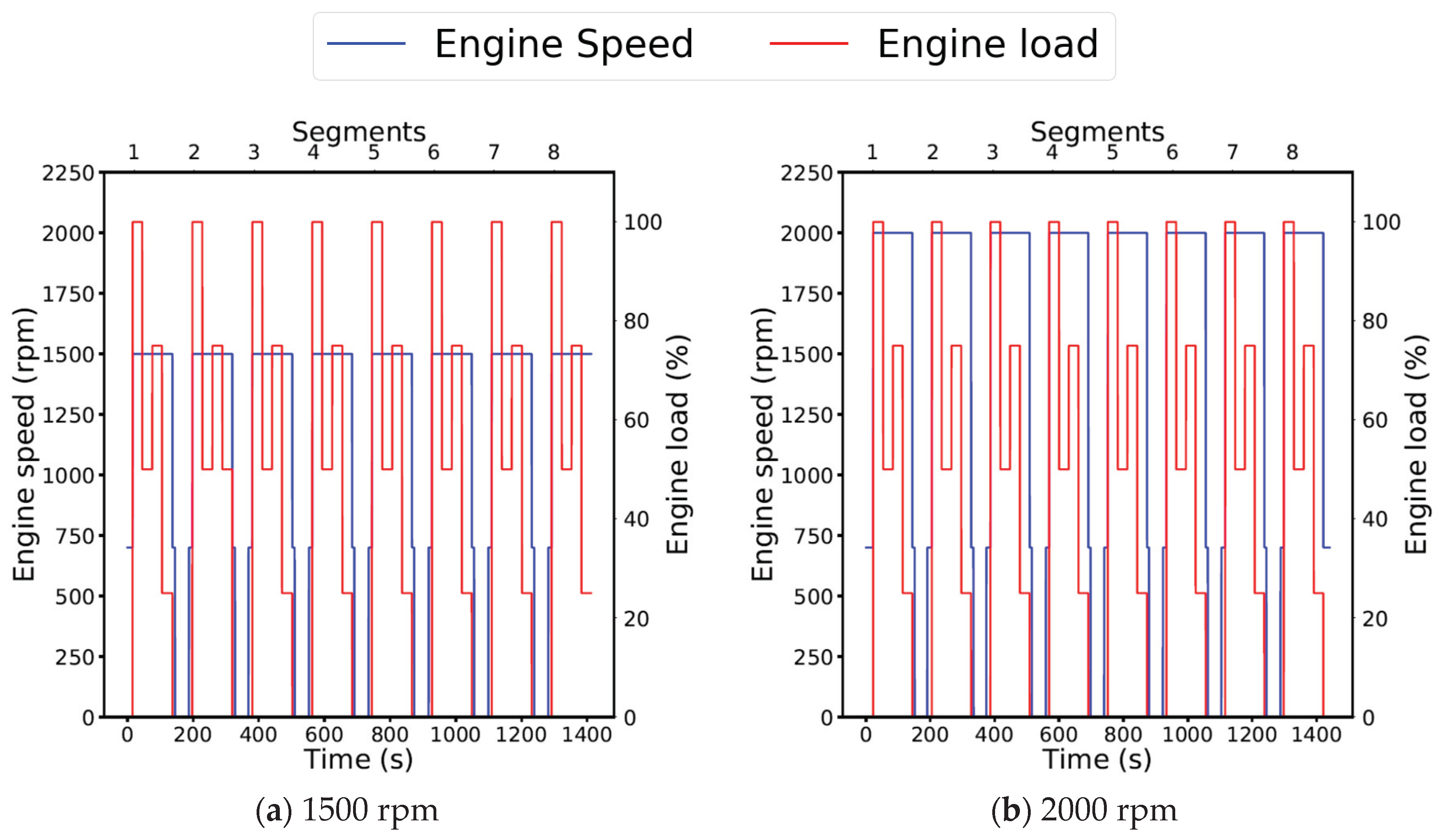
Figure 1. Engine speed and commanded engine load in the custom designed experimental cycle at (a) 1500 and (b) 2000 rpm. The blue line corresponds to the engine speed and the red line corresponds to the engine load.
Applsci 10 03839 g001
Figure 2. Mean values of indicated mean effective pressure (IMEP) (kPa) (a) and NOx (g/kWh) (b) at full load in all segments for experiments 1, 2 and 3 at 2000 rpm. The blue circle represents Experiment 1, the red diamond Experiment 2 and the green pentagon Experiment 3.
Applsci 10 03839 g002
Figure 3. Coolant and oil temperatures during the custom drive cycle tests at (a) 1500 and (b) 2000 rpm. The blue line corresponds to the coolant temperature and the red line corresponds to the oil temperature.
Applsci 10 03839 g003
Figure 4. Coolant temperature at each load in each segment at (a) 1500 and (b) 2000 rpm. The blue circle represents 100% load, the red diamond 50% load, the green pentagon 75% load and the pink hexagon 25% load.
Applsci 10 03839 g004
Figure 5. Lubricating oil temperature at each load in each segment at (a) 1500 and (b) 2000 rpm. The blue circle represents 100% load, the red diamond 50% load, the green pentagon 75% load and the pink hexagon 25% load.
Applsci 10 03839 g005
Figure 6. IMEP at each load in each segment at (a) 1500 and (b) 2000 rpm. The blue circle represents 100% load, the red diamond 50% load, the green pentagon 75% load and the pink hexagon 25% load.
Applsci 10 03839 g006
Figure 7. Brake mean effective pressure (BMEP) at each load in each segment at (a) 1500 and (b) 2000 rpm. The blue circle represents 100% load, the red diamond 50% load, the green pentagon 75% load and the pink hexagon 25% load.
Applsci 10 03839 g007
Figure 8. Friction mean effective pressure (FMEP) at each load in each segment at (a) 1500 and (b) 2000 rpm. The blue circle represents 100% load, the red diamond 50% load, the green pentagon 75% load and the pink hexagon 25% load.
Applsci 10 03839 g008
Figure 9. Normalised FMEP (by IMEP) at each load in each segment at (a) 1500 and (b) 2000 rpm. The blue circle represents 100% load, the red diamond 50% load, the green pentagon 75% load and the pink hexagon 25% load.
Applsci 10 03839 g009
Figure 10. Indicated specific fuel consumption (ISFC) at each load in each segment at (a) 1500 and (b) 2000 rpm. The blue circle represents 100% load, the red diamond 50% load, the green pentagon 75% load and the pink hexagon 25% load.
Applsci 10 03839 g010
Figure 11. Brake specific fuel consumption (BSFC) at each load in each segment at (a) 1500 and (b) 2000 rpm. The blue circle represents 100% load, the red diamond 50% load, the green pentagon 75% load and the pink hexagon 25% load.
Applsci 10 03839 g011
Figure 12. Start of injection at each load in each segment at (a) 1500 and (b) 2000 rpm. The blue circle represents 100% load, the red diamond 50% load, the green pentagon 75% load and the pink hexagon 25% load.
Applsci 10 03839 g012
Figure 13. Cumulative energy released from combustion at each load in each segment at (a) 1500 and (b) 2000 rpm. The blue circle represents 100% load, the red diamond 50% load, the green pentagon 75% load and the pink hexagon 25% load.
Applsci 10 03839 g013
Figure 14. Average exhaust temperature at each load in each segment at (a) 1500 and (b) 2000 rpm. The blue circle represents 100% load, the red diamond 50% load, the green pentagon 75% load and the pink hexagon 25% load.
Applsci 10 03839 g014
Figure 15. NOx emissions (g/kWh) at each load in each segment at (a) 1500 and (b) 2000 rpm. The blue circle represents 100% load, the red diamond 50% load, the green pentagon 75% load and the pink hexagon 25% load.
Applsci 10 03839 g015
Figure 16. HC emissions (g/kWh) at each load in each segment at (a) 1500 and (b) 2000 rpm. The blue circle represents 100% load, the red diamond 50% load, the green pentagon 75% load and the pink hexagon 25% load.
Applsci 10 03839 g016
Figure 17. Fuel-to-air equivalence ratio at each load in each segment at (a) 1500 and (b) 2000 rpm. The blue circle represents 100% load, the red diamond 50% load, the green pentagon 75% load and the pink hexagon 25% load.
Applsci 10 03839 g017
Table 1. Specifications of the engine used in the current study [33].
S. NoModelCummins ISBe220 31
1Cylinders6 in-line
2Capacity5.9 L
3Bore x stroke102 × 120 (mm × mm)
4Connecting rod220 mm
5Maximum power162 kW @ 2000 rpm
6Maximum torque820 Nm @ 1500 rpm
7Compression ratio17.3:1
8AspirationTurbocharged
9Fuel injectionHigh pressure common rail
10Emissions standardEuro III