1. Introduction
Large diameter steel ring and/or stringer-stiffened cylinders are widely used in marine structures as a major structural component of floating offshore installations, main legs of tension leg platforms, submarine hulls, and spars. Recently, these structures are also applied extensively in floating offshore wind turbine foundations. The major advantages of stiffened cylinders are good axial compressive and external pressure loading, and low drag resistance force by passing fluid.
During operation, stiffened cylindrical members may be potentially damaged caused unexpected loading such as ship collisions (such as tugboats, commercial ships, ferryboats, support vessels, and private vessels), groundings, slamming, or the impact of dropped heavy objects. In these accidents, ship collisions have been highlighted as the most significant cause of damage or even catastrophic loss of offshore installations due to loss of structural integrity [
1]. A minor collision will result in only repairable local damage to the structure and probably will not call for a stop of operation. However, the major collision will damage cylindrical structures globally, and assuredly require a stop of operations. Therefore, it is a necessity to increase attention on the influences of collision damage on the strength of the structure and serviceability in the initial design step for safety concerns.
To evaluate the internal mechanics of cylindrical structures based on collision events, many approaches are applied such as empirical formulation, simplified analytical method, finite element modeling (FEMs), and experiments. However, it is difficult to perform full-scaled cylindrical collision experiments, and sometimes impossible, because of extremely costly and technological requirements. Thus, small-scale laboratory model tests are the most convincing methods for evaluating the impact resistance of cylindrical structures. There are relatively few studies that provided the experiments on ring and/or stringer-stiffened cylinders subjected to dynamic mass impact. Cerik et al. [
2] presented the drop-weight impact test on two fabricated steel ring-stiffened cylinders. The damage was created by using the striking mass with a knife-edge indenter. Ghazijahani et al. [
3] provided the experiment on 27 locally dented unstiffened cylinders under compression. The dent imperfections of different depths, locations, and orientations were considered. It was found that the dented area was largely affected by the deformations in the buckling modes and buckling strengths. They also presented the experimental study on 14 thin-walled intact and dented cylindrical shells subjected to external pressure [
4], 8 damaged tubular members under bending loads [
5], and 6 locally dented conical shell models under axial compression [
6]. In general, the ultimate load-carrying capacity of dented structures was strongly decreased when compared with the intact structures.
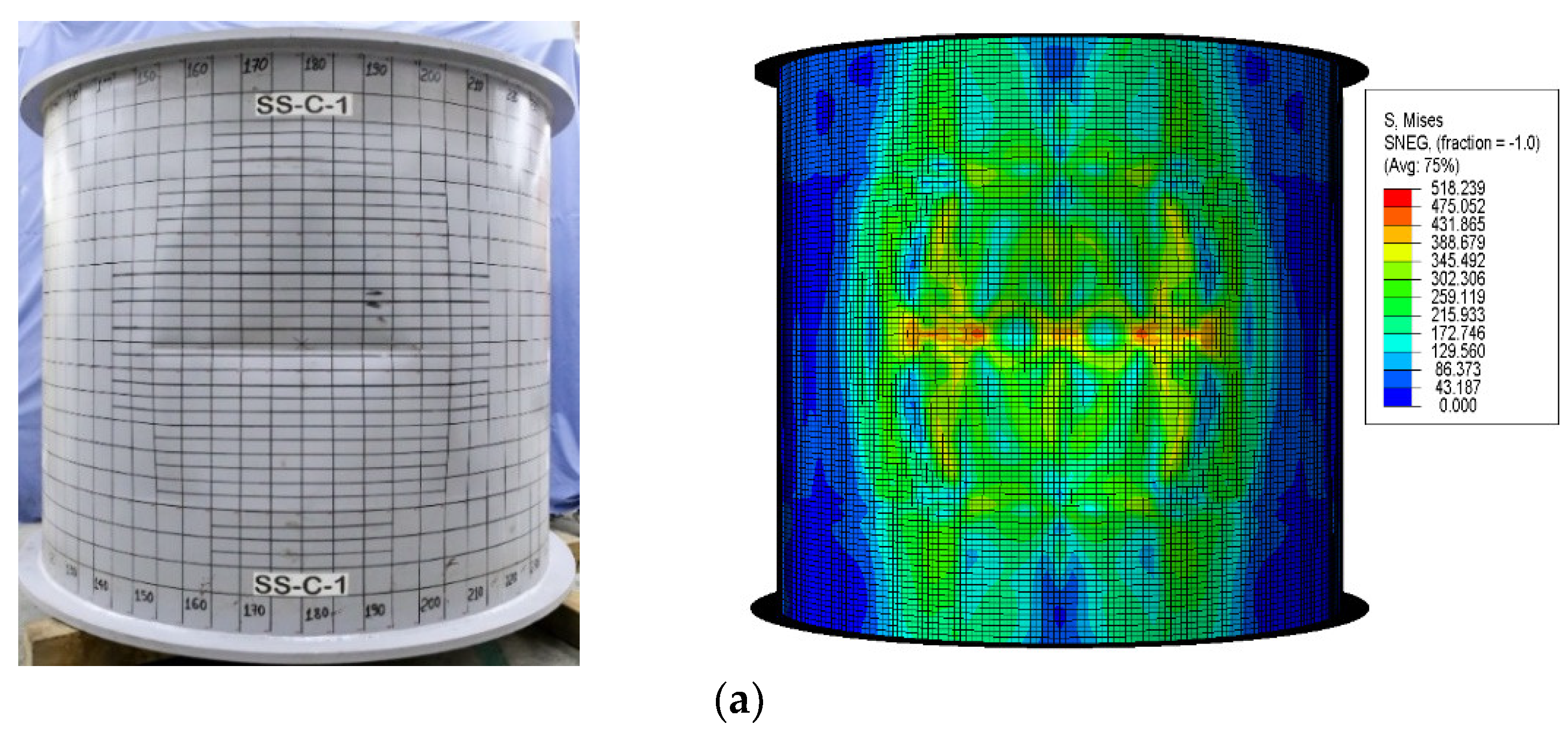
Recently, Do et al. [
7] conducted the dynamic mass impact tests on two stringer-stiffened cylinders (denoted as SS-C-1 and SS-C-2) with local impact at mid-span. The specimens had three bays each, divided by two T-shaped ring-stiffeners and stiffened with 20 stringer-stiffeners in axial direction, respectively. These models were then performed under external hydrostatic pressure to assess the residual strength of these structures after collision [
8]. Do et al. [
9] provided details of the second series on two ring-stiffened cylinders, namely, RS-C-3 and RS-C-4. These models had seven bays and were separated by six flat-bar ring-stiffeners. The damage was performed by the free-fall testing frame and their residual strengths were checked under external hydrostatic pressure by pressure chamber. In these references, the test results are very valuable for a common understanding of the dynamic impact behaviors of stiffened cylinders. Furthermore, they can be used to validate the numerical analyses or derive the analytical formulations for collision response of stiffened cylinders.
For assessment of local denting of cylindrical shells, only a few analytical studies were provided by Wierzbicki et al. [
10,
11,
12], Hoo Fatt et al. [
13], and Moussouros et al. [
14]. They focused on deriving the simplified formulae to predict the quasi-static denting behaviors of stiffened cylinders. Simplified formulae are the most rapid tools for predicting the impact strength of cylinder structures, especially during the initial design stage and the risk assessment. In these studies, the cylindrical shell is assumed as perfectly plastic material and neglected the elastic strains in the damage areas. It is also assumed that the outside of the damage regions is rigid, and that the plastic damage zone is localized and finite. However, in real structural behaviors, the dynamic strain rate effects and inertial forces should be considered for assessing the extent of local denting damage accurately [
15]. Furthermore, in these formulations, the force-displacement and deformation profile is not smooth because of sudden jumps in the vicinity of the stiffeners and it does not match well the experimental observations. Because these researches are purely theoretical, they are required to be verified with reliable test data. Detailed explanations of these formulations are given in
Section 5.
More recently, Cerik et al. [
2] improved the existing formulations proposed by Hoo Fatt and Wierzbicki [
13] for the local denting behavior of ring-stiffened cylinders. He revised the circumferential bending resistance by including the effect of the ring stiffeners and changing the fully plastic bending moment of the cylindrical shell by an equivalent bending moment per length. This simple formulation has good accuracy when compared to the limited experimental data. However, more studies are needed to validate this analytical approach with a wide range of geometry and reliable test data. Another approximate formulation to forecast the permanent local denting damage of the ring-stiffener cylinder was reported by Do et al. [
9]. These formulations are derived using the FEA results of rigorous case studies on the real design full-scale ring-stiffened cylinders. It has high accuracy when compared with available test models. However, there are several shortcomings existing in these formulations. First, the impact location was considered in these formulations only at mid-bay of the ring-stiffeners and perpendicular to the axial direction. In actual cases, the impact position is varying on the cylinder structures. It is clear that the impact behavior of the stiffened cylinder was sharply improved when impact locations were close to ring stiffener [
7]. Thus, the effects of various impact locations need to consider predicting the extent of damage to cylinder structures. Secondly, the damage deformations were only generated by a rigid knife-edge indenter with a rounded tip, but the striking mass in a real case is not only a knife-edge indenter but also a hemispherical or rectangular indenter type. Therefore, to get accuracy of the extent of damage prediction, all the information on striking mass types should be investigated. To overcome these shortcomings, the proposed formulations developed in this study for assessing the permanent local dent depth, include all parameters such as impact location factor, impact angle factor, and indenter shape factor. To the best of the authors’ knowledge, until recently, there was no reliable equation or code recommendation for assessing the permanent damage of ring- or/and stringer-stiffened cylinders under dynamic mass impact loading. Therefore, it is sorely needed to propose the new formulations to predict the extent of local dent depth of these structures, and this study’s objective is to fill that gap.
Nowadays, finite element modeling (FEM) is an excellent tool for predicting ship collisions and groundings. Numerical assessment of cylinder structures under collision loading conditions has been performed by many researchers [
16,
17,
18,
19,
20,
21,
22,
23]. The nonlinear FEA was also used to perform ship–ship collisions [
24,
25,
26,
27], validation of the analytical solutions [
28,
29], and experimental results [
30,
31,
32]. Furthermore, FEM has the convenience of incorporating full-scale actual structures and all parameters such as material properties (strain hardening and strain rate effects), loadings and boundary conditions, and other structures for both striking ships and offshore structures. Thus, besides the computational economic efficiency, a carefully implemented nonlinear FEA, which is also confirmed with reliable test models, would be the most effective approach of evaluating the collision responses of offshore structures.
In this background, this study aims to derive the new formulations to evaluate the permanent local damage of steel ring- or/and stringer-stiffened cylinders under dynamic lateral mass impact. Based on the regression analysis of the rigorous parametric study results by nonlinear FEA, new empirical formulations were proposed and compared with available test results and existing analytical equations.
4. Derivation of Empirical Formulation
After investigating the effects of various parameters on the impact response of stiffened cylinders in the previous section, the series of parametric studies were performed on actual design scantlings of ring- and/or stringer-stiffened cylinders, such as an actual submarine design concept and tension leg platforms in the ABS [
37] and API [
38] rules. The numerical analysis strategy method developed in the previous section was used. The details of dimension and material properties were provided in
Table 7 and
Table 8 for stringer-stiffened cylinders and ring-stiffened cylinders, respectively. The range of
R/t for reference ring-stiffened cylinder was determined from 97 to 454, while that of reference stringer-stiffened cylinder was from 111 to 475.
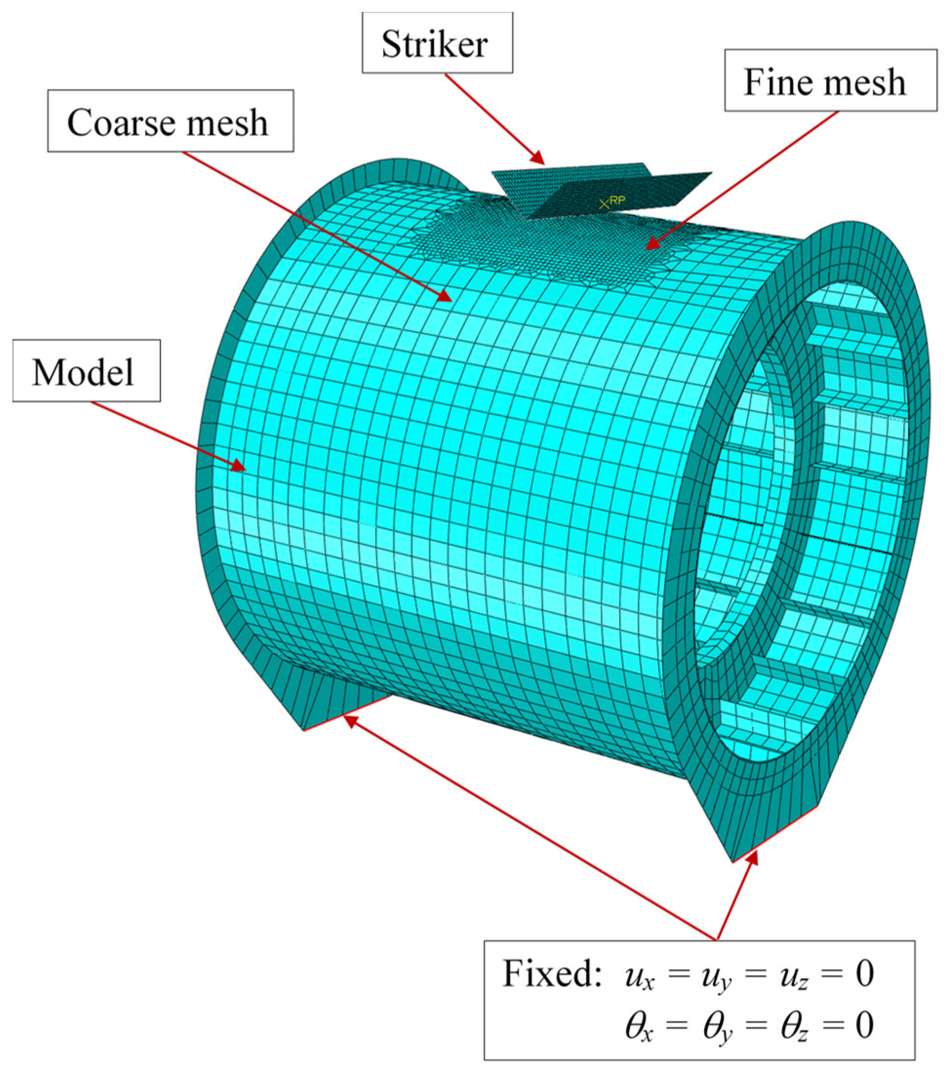
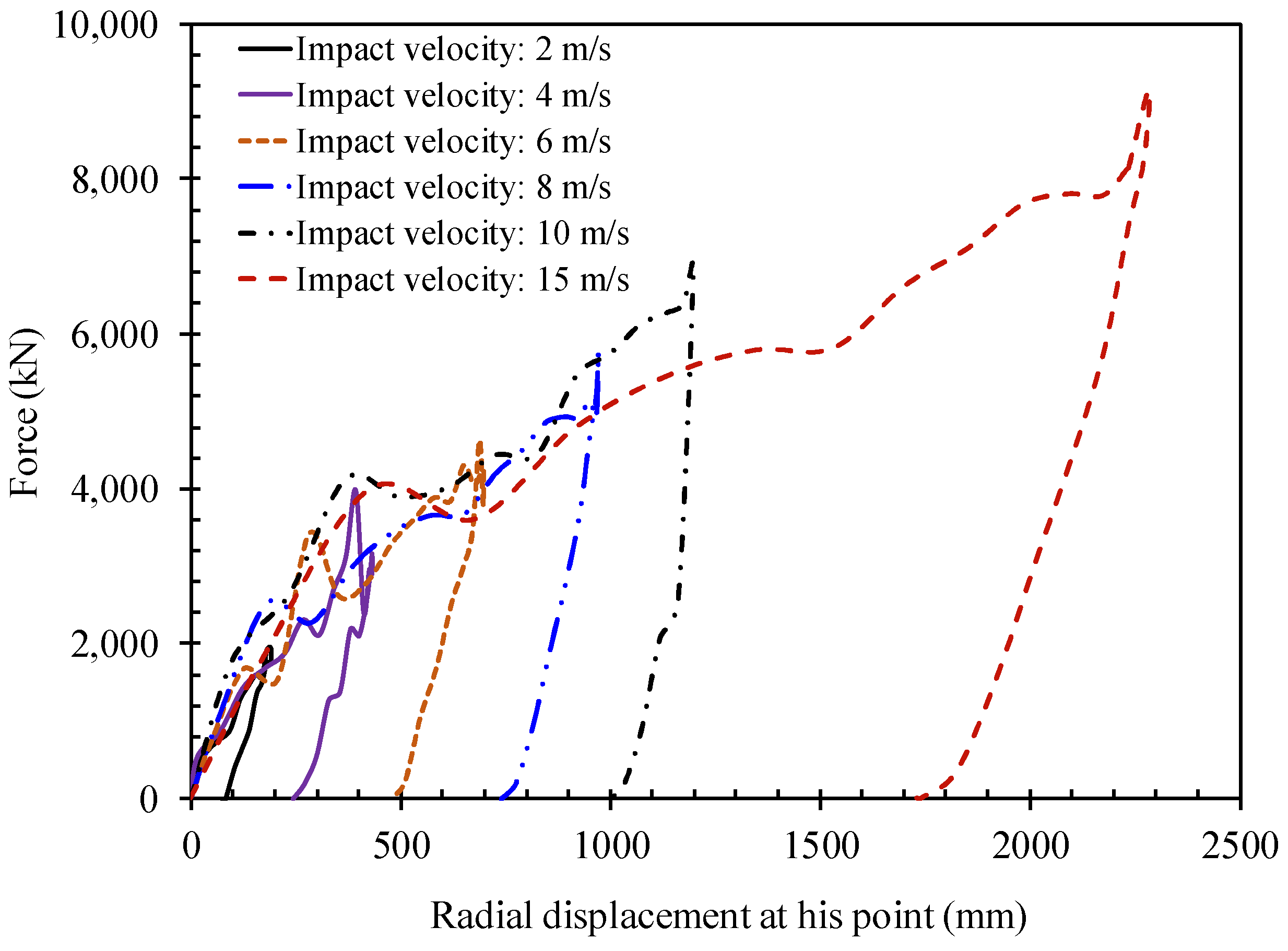
In collision analysis, the rigid hemisphere indenter was applied for generating the damage on the model. For each model, the series of numerical analysis were performed with different impact velocities from 1.0 m/s, 2.5 m/s, 5.0 m/s, 7.5 m/s, and 10 m/s. These selected velocities have represented the collisions of offshore installations with dropped objects from platform decks or floating objects, which were large enough to achieve the plastic deformation of the dented stiffened cylinder without any fracture occur. The striker masses were 10 tons, 20 tons, 50 tons, and 100 tons with each velocity, respectively. Additionally, the collision of offshore installations with supply vessels is also considered. The impact velocities were 1 m/s, 2 m/s, and 3 m/s. For each velocity, the striker masses were 1000 tons, 3000 tons, 5000 tons, and 7500 tons for the stringer-stiffened cylinder. It should be noted that the added mass was assumed to be 10% to 40% of striker mass. Thus, there were a total of 200 and 256 numerical analysis cases for ring-stiffened and stringer-stiffened cylinders, respectively. Subsequently, these parametric study results were used to derive empirical equations for predicting the local denting damage of stiffened cylinders.
The procedure to derive empirical formulations for assessment of permanent local denting damage as following steps:
- ○
Step 1: Selecting the scantling of actual design example ring- and/or stringer-stiffened cylinders.
- ○
Step 2: Performing finite element analysis to assess the collision response of each model.
- ○
Step 3: Preparation of non-dimensional form of geometric properties and collision loadings for applying in the derived formulations.
- ○
Step 4: Checking the degree of dependence of explanatory variables.
- ○
Step 5: Performing the regression analysis to find the best-fit curve by using the strongly-influenced parameters in the previous step.
- ○
Step 6: Checking the accuracy of the proposed formulations.
- ○
Step 7: Checking the skewness of Xm (ratio of the numerical results to the proposed formulation results) against the basic parameters.
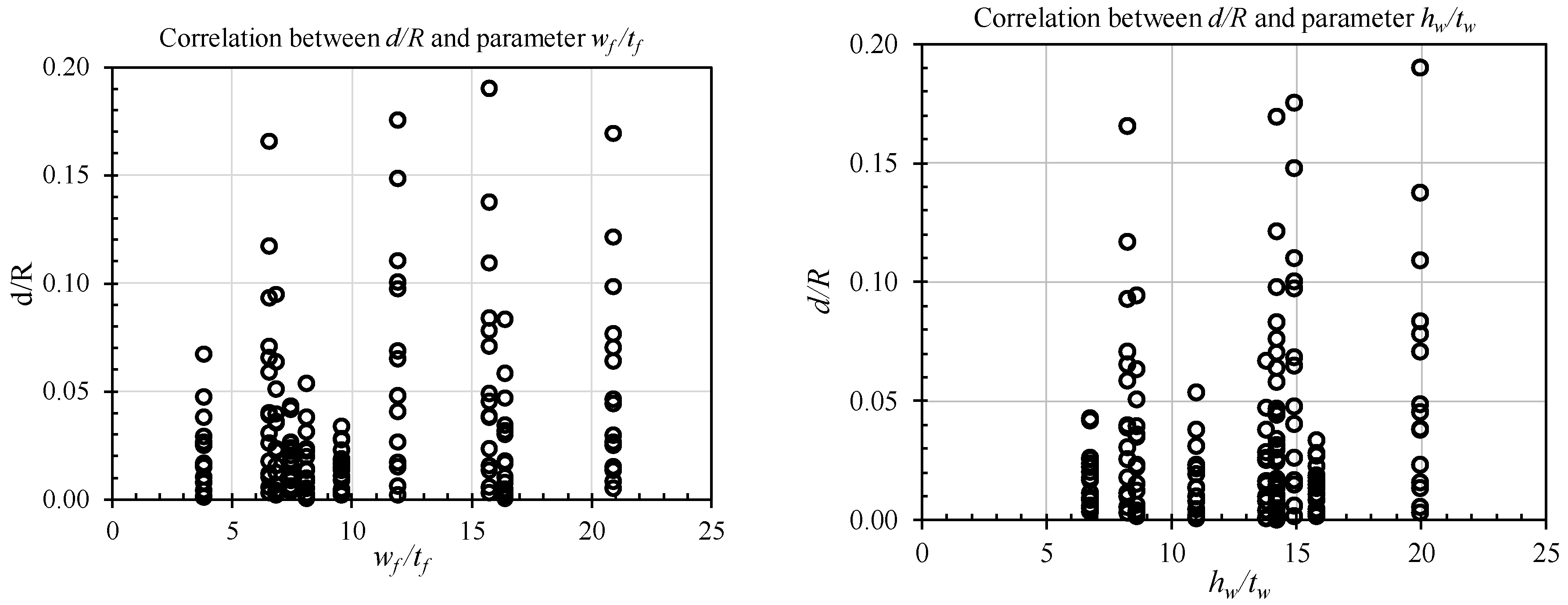
4.1. Ring-Stiffened Cylinder
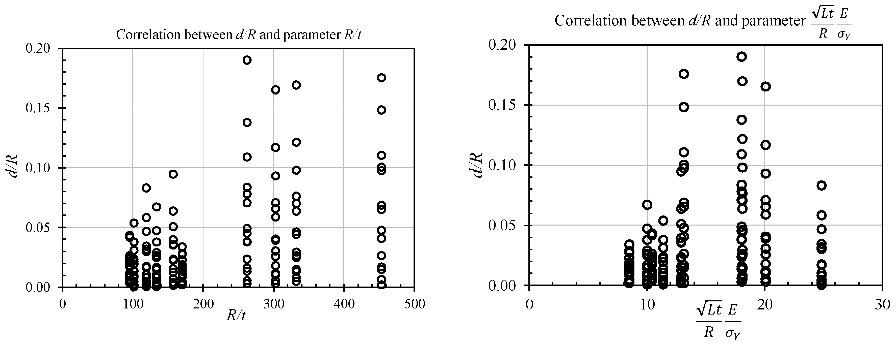
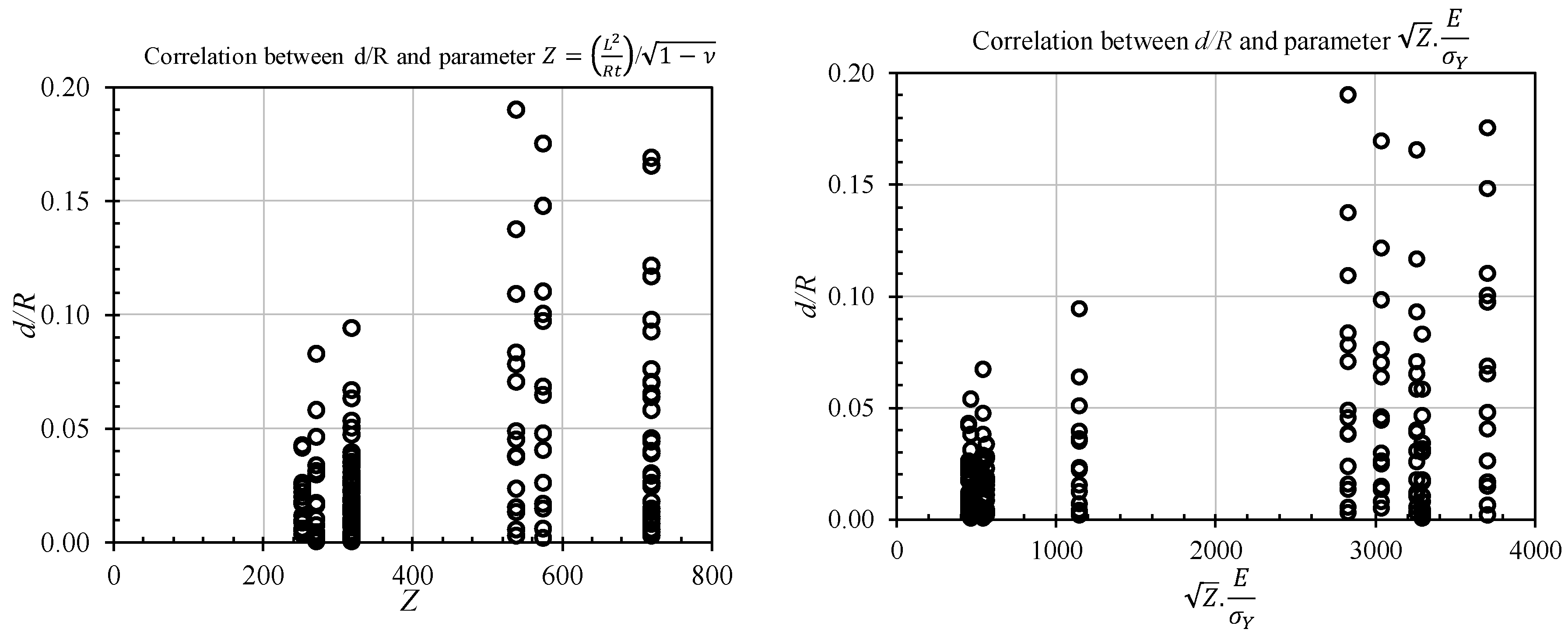
To find a suitable dependent basis parameter on which to derive the local denting damage
δd (
δd =
d/R), the relationship between
δd and various appropriate non-dimensional geometric and material property parameters were considered such as
Ls/R, Ls/t,
wf/tf and
hw/tw,
E/σY, and
λE (where
Ls: ring stiffener spacing;
R: mean radius;
t: shell thickness; and
wf, tf,
hw, and
tw are flange width, flange thickness, web height, and web thickness of ring-stiffener, respectively; E: Young’s modulus;
σY: yield strength; and
λE: energy ratio). Additionally, the combination of different parameters was also evaluated in order to identify the most reasonable method of deriving
δd formulation, which included Batdorf slenderness
; and multiplying of Batdorf coefficient with material properties
and apart from multiplying the constant of
(where
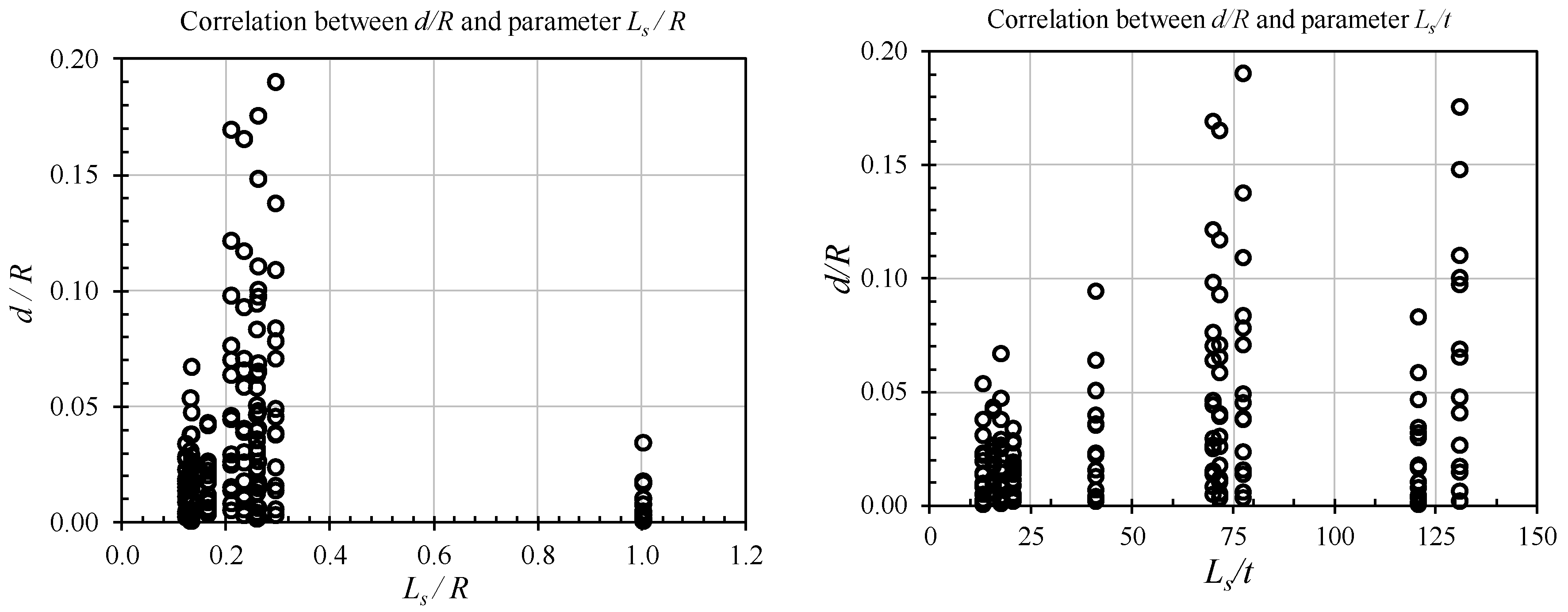
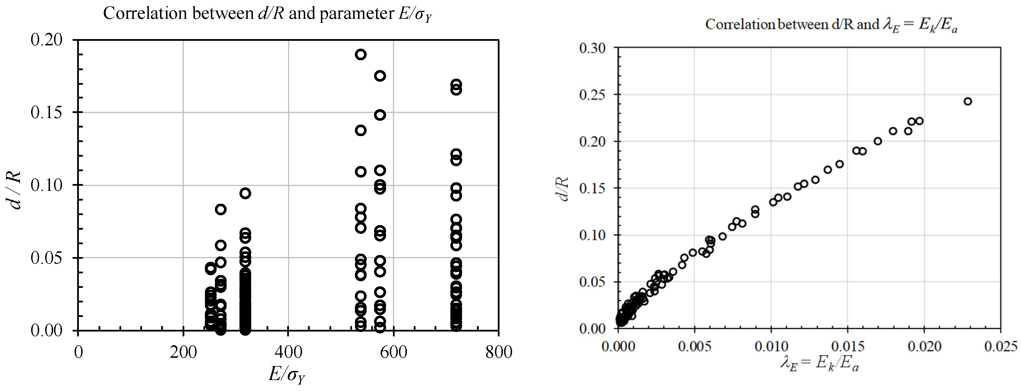
: Poisson ratio). The degree of dependence and trends are indicated in
Figure 16,
Figure 17,
Figure 18,
Figure 19 and
Figure 20. Generally, the trend of parameter of
Ls/R, Ls/t,
wf/tf, and
hw/tw has less influence on
δd. Another factor
E/σy also has less effect, but in the real case, material properties played an important effect on
δd. Therefore, this parameter will be included in the combination of basic variables. It can be seen that the ratio of energy parameter
λE is shown to have the strongest effect on
δd. The energy ratio
λE is the ratio of impact kinetic energy of the striker
() to the energy absorption capacity of the struck structure (
). This parameter was used for deriving
δd.
After investigating the dependent parameters, the regression analyses were performed using the best-fit curve of numerical values as shown in
Figure 21. The mean of the uncertainty modelling factor (
Xm) was quite good with 0.996, while the coefficient of variation (COV) was 6.32%. It is remarkable that the values of maximum permanent dent depth (
d) in
Figure 21 were less than 0.5% of the cylinder radius (
R), and they were not included because these values can be allowed as the initial imperfections according to the upper limit of tolerable initial imperfection of BSI [
39] for ring-stiffened cylinders. The simple formulations were derived to predict the maximum of permanent dent depth of ring-stiffened cylinders as shown in Equation (15), which is corresponded to mean curve with discontinue line. When considering the safety design, the design equation is provided in Equation (16), which is determined by multiplying mean curve with (mean + 2 × σ) as continue line in
Figure 21. Where σ is the standard deviation of mean equation;
δd is non-dimensional dent depth.
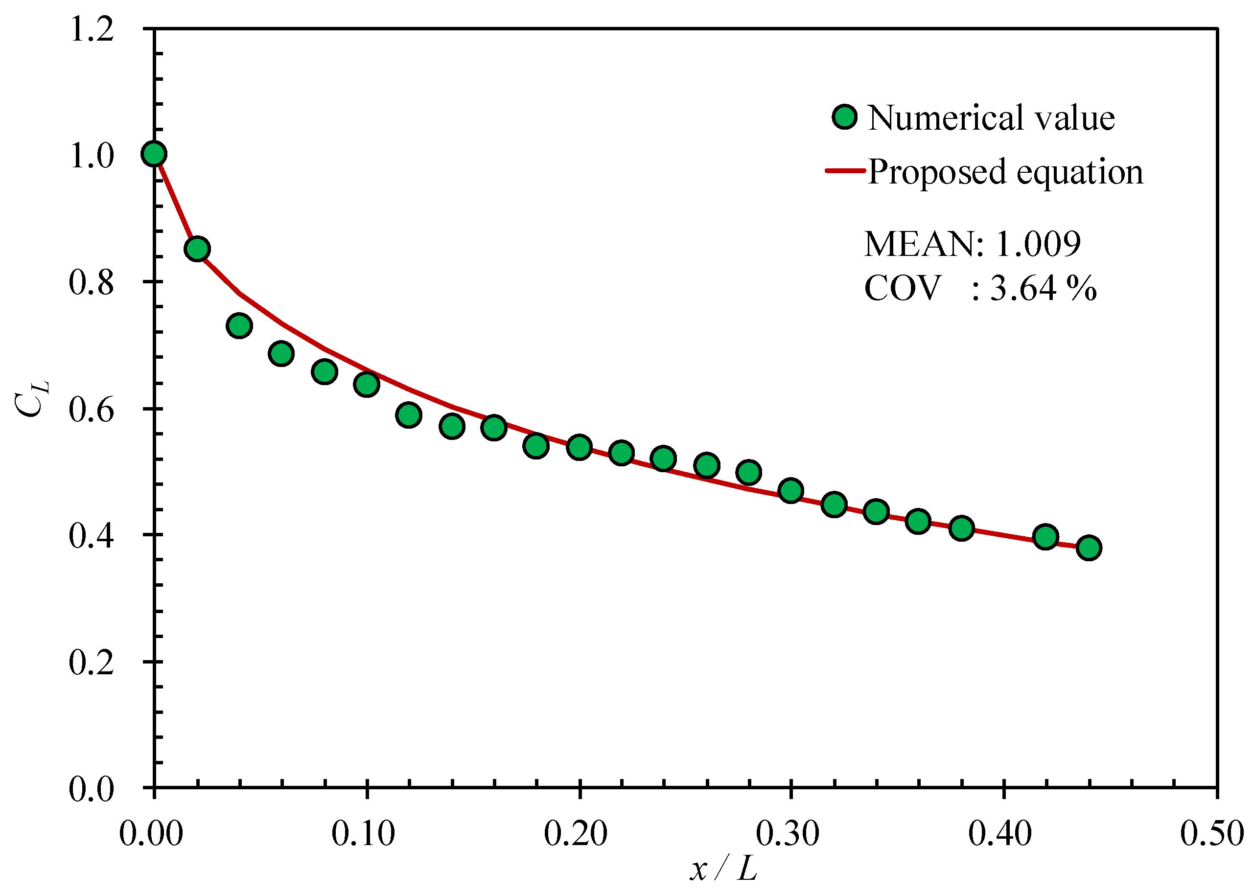
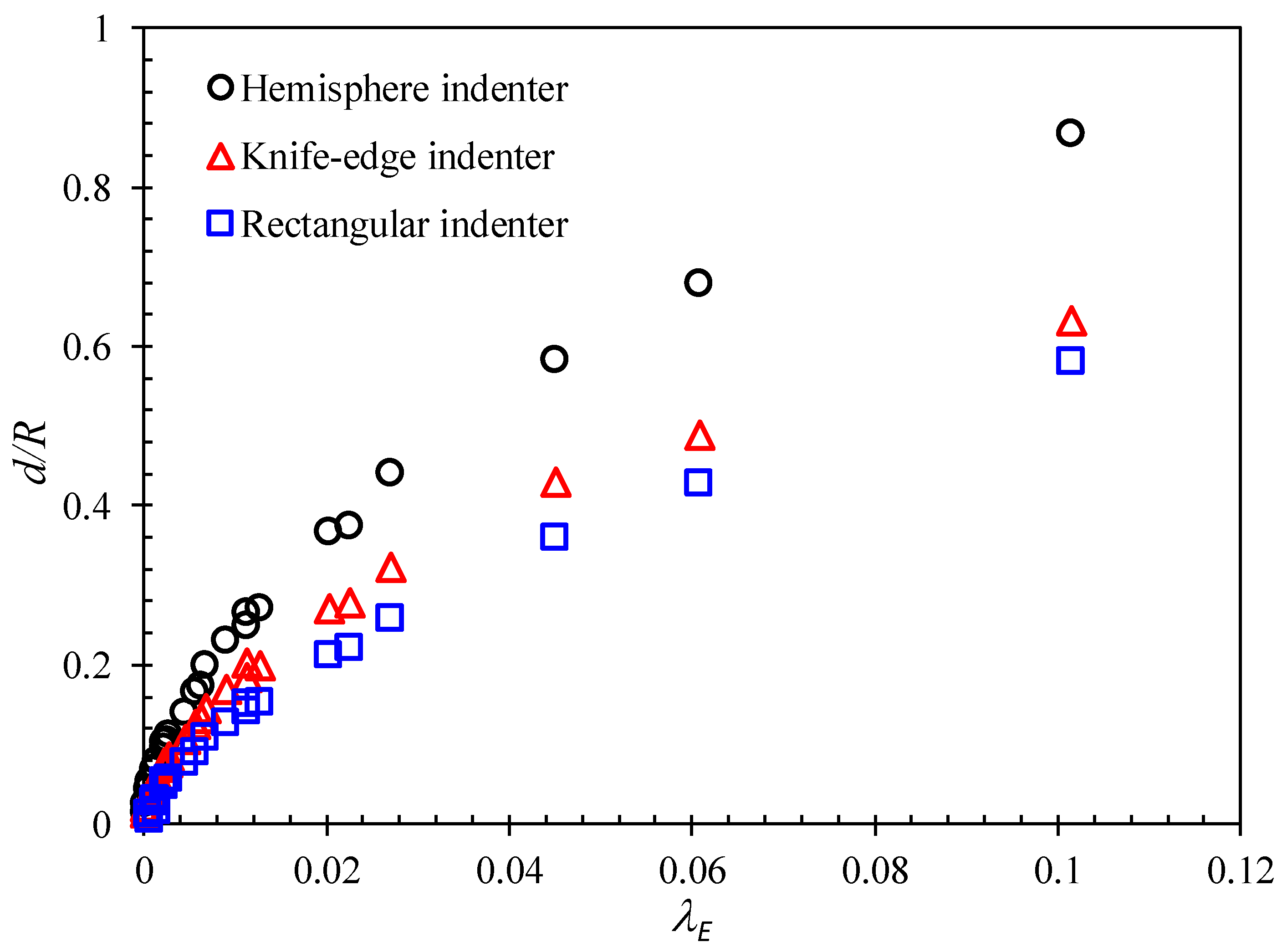
The proposed formulation in Equation (15) developed in this study for predicting the permanent local denting damage includes some parameters: indenter shape factor (
Cs), impact location factor (
CL), and impact angle factor (
Cβ). Where the indenter shape factor (C
s) is 1.0 when the striking mass is the hemisphere indenter, while that of 0.81 with the knife-edge indenter and it is 0.68 for the rectangular indenter shape. The impact location factor is determined as Equation (17), which is strongly dependent on the distance of impact position (
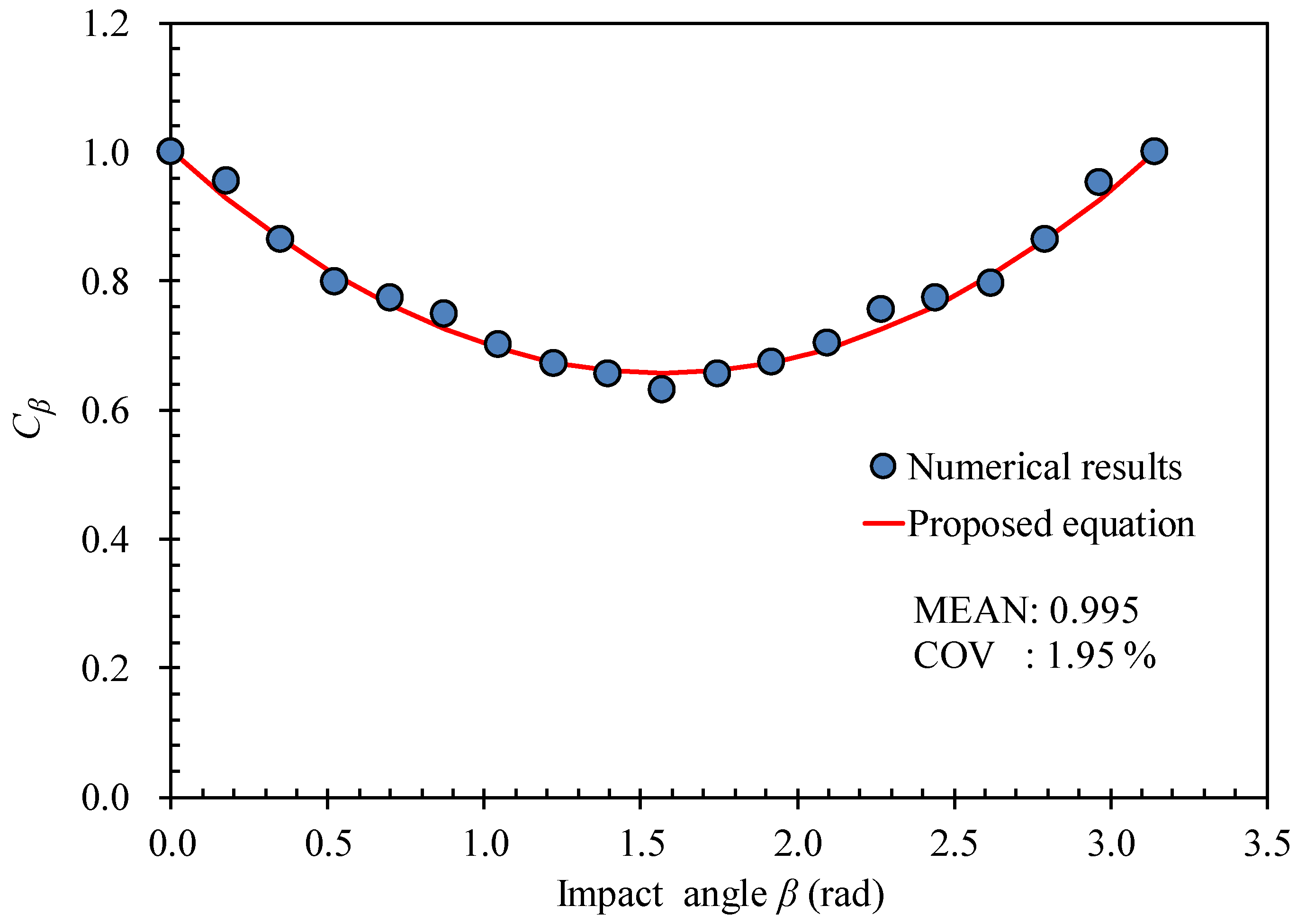
to mid-span of the ring-stiffened cylinder. The effect of impact angle on collision response can be calculated as Equation (18), where
is impact angle with unit rad. The next parameter in Equation (15) is energy ratio (
λE), which is evaluated by Equation (19), where
Ek is the kinetic energy of the striker, as defined in Equation (20), and
Ea is the energy absorption capacity of struck structure, as provided in Equation (21). The structure volume was quickly determined in Equation (22). Additionally, the ultimate strength (
σT) and ultimate strain (
εT) can be calculated by Equations (23)–(26) for general steel and marine steel, respectively. These Equations (23)–(26) are empirical equations and derived using the results of 7500 tensile test specimens [
35].
where
CS: indenter shape factor (CS = 1: Hemisphere indenter; CS = 0.81: Knife-edge indenter;
CS = 0.68: Rectangular indenter),
CL: impact location factor, and
Cβ: impact angle factor.
x: distance from collision to mid-span of the ring-stiffened cylinder,
L: total length of the ring-stiffened cylinder, and
β: impact angle (rad)
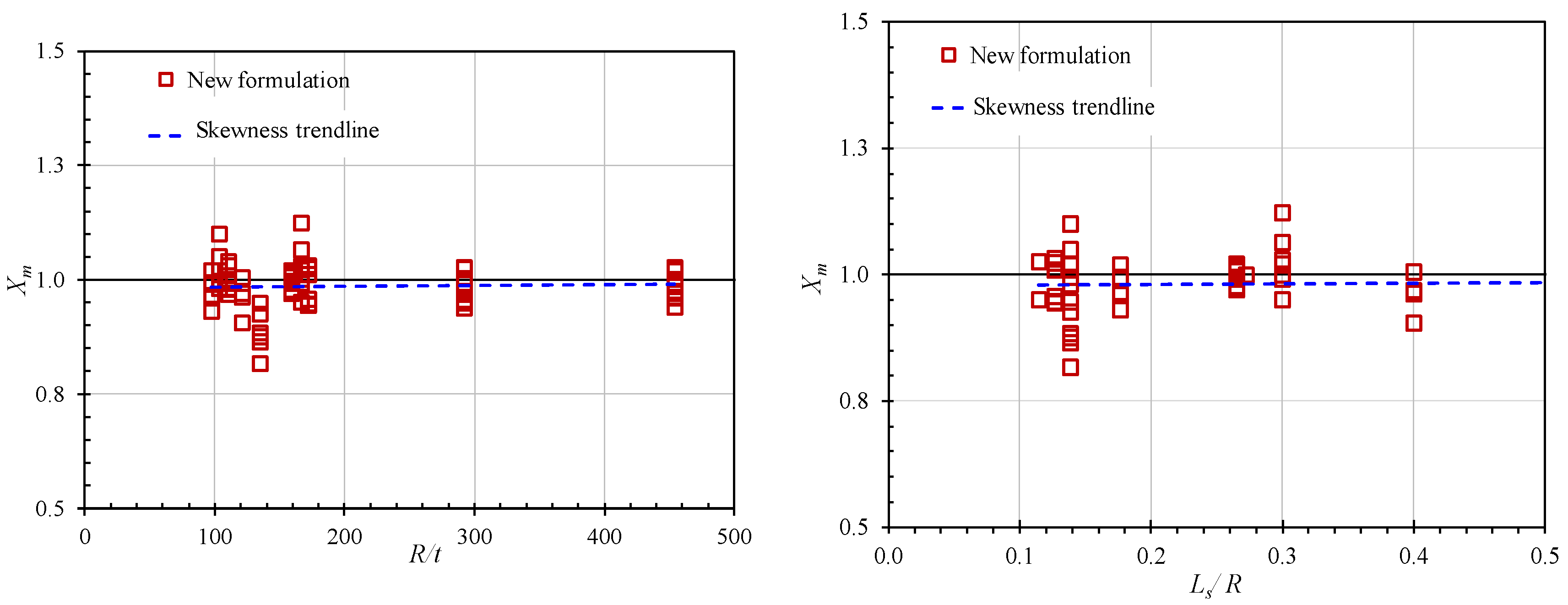
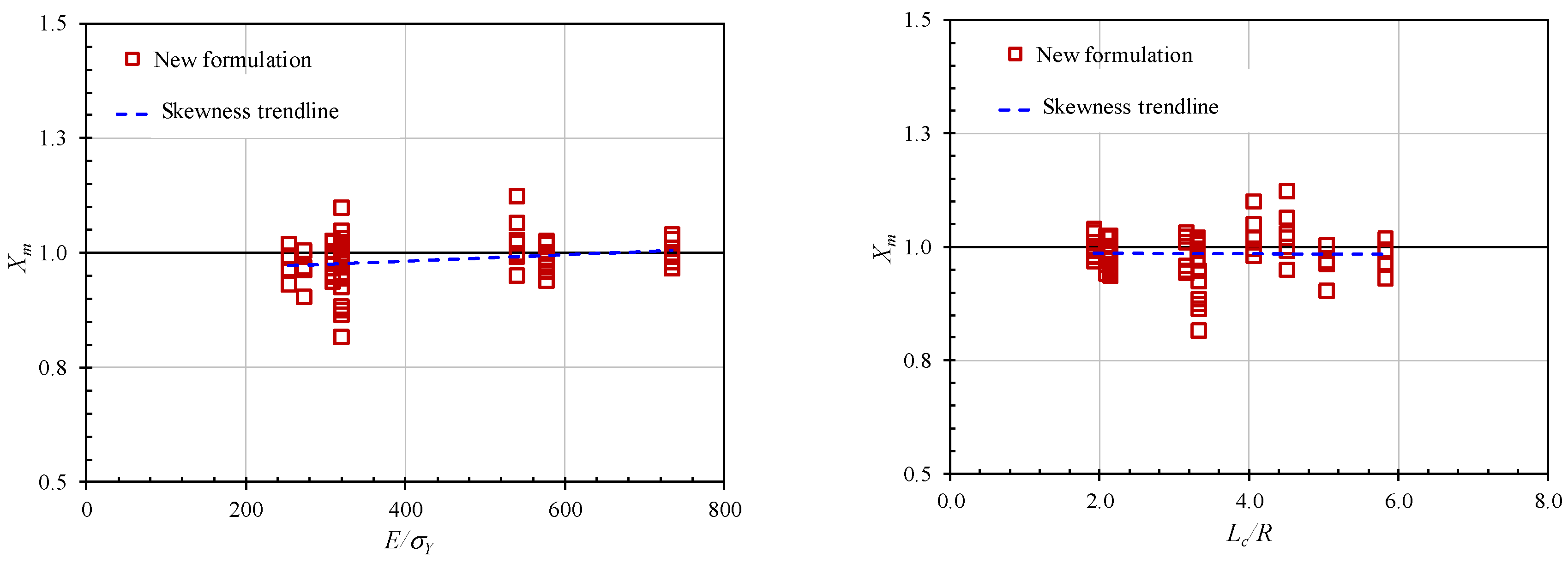
As mentioned in the previous section, after deriving the proposed equation, the final step is to check the skewness of
Xm against the basic parameters using the cross-validation charts. This step is vital in the regression diagnostic process to derive the design formula. If skewness strongly occurred with basic parameters, it means that these parameters should be included in the proposed formulation. The plotting of
Xm against basis non-dimensional parameters (
R/t, Ls/R, hw/tw,
wf/tf, E/σY, and
Lc/R) is illustrated in
Figure 22,
Figure 23 and
Figure 24. It can be seen that there was no apparent skewness and no sharpness trend line in these figures. Therefore, it is concluded that the accuracy and reliability of the proposed formulations are acceptable to predict the maximum permanent local denting damage under dynamic collision.
4.2. Stringer-Stiffened Cylinder
The procedures to derive the formulation to predict the local denting damage of a stringer-stiffened cylinder are similar to procedures applied to a ring-stiffened cylinder in the previous
Section 4.1. First, the correlations between
δd and various parameters were checked. It is included non-dimensional geometric (
Ls/R, Ls/t,
hrw/trw,
hsw/tsw, and
wsf/tsf) and material property parameters (
E/σY and
λE) and combinations of variable parameters (
: Batdorf slenderness;
and
). The results also indicated that energy ratio
λE is the strongest parameter affected by
δd. Then, the regression analysis was performed, and Equations (27)–(30) were derived as functions of the energy ratio (
λE) to predict the maximum permanent dent depth of the stringer-stiffened cylinder under dynamic mass impact. It is noteworthy that the maximum permanent dent depth values (
d) smaller than 0.25% of the cylinder diameter (
D) were not considered, which corresponded to the upper limit of tolerable imperfection for stringer-stiffened cylinders by API [
38]. The Equation (27) is a mean equation while that of Equation (28) is the design equation. It is noted that when considering the purposes of the safety design under hazard and risk conditions of marine structures, the design equation, which is determined by multiplying the mean curve with (Mean + 2 × Standard deviation), should be used. These proposed formulations could be used easily for the purposes of the initial design without any time-consuming FEM analysis.
The accuracy of the proposed formula was quite good, with
Xm (ratio of predicted values from Equation (27)/numerical values) of 0.987 together with a COV of 8.60%. In these equations, the effect of striker header shapes and impact locations, as well as impact angles, was also considered as the reduction factor
CS,
CL, and
Cβ, respectively. The most severe case is when the load is applied through a hemispherical indenter, which resembles highly localized point loading with
CS = 1, then
CS = 0.74 and
CS = 0.63 for the knife-edge indenter and rectangular indenter, respectively. Therefore, the proposed formulation was derived based on the most severe case of a hemispherical indenter. The effects of impact locations and impact angles were considered as Equations (29) and (30), respectively.
where
CS: indenter shape factor (CS = 1: Hemisphere indenter; CS = 0.74: Knife-edge indenter;
CS = 0.63: Rectangular indenter),
CL: impact location factor, and
Cβ: impact angle factor.
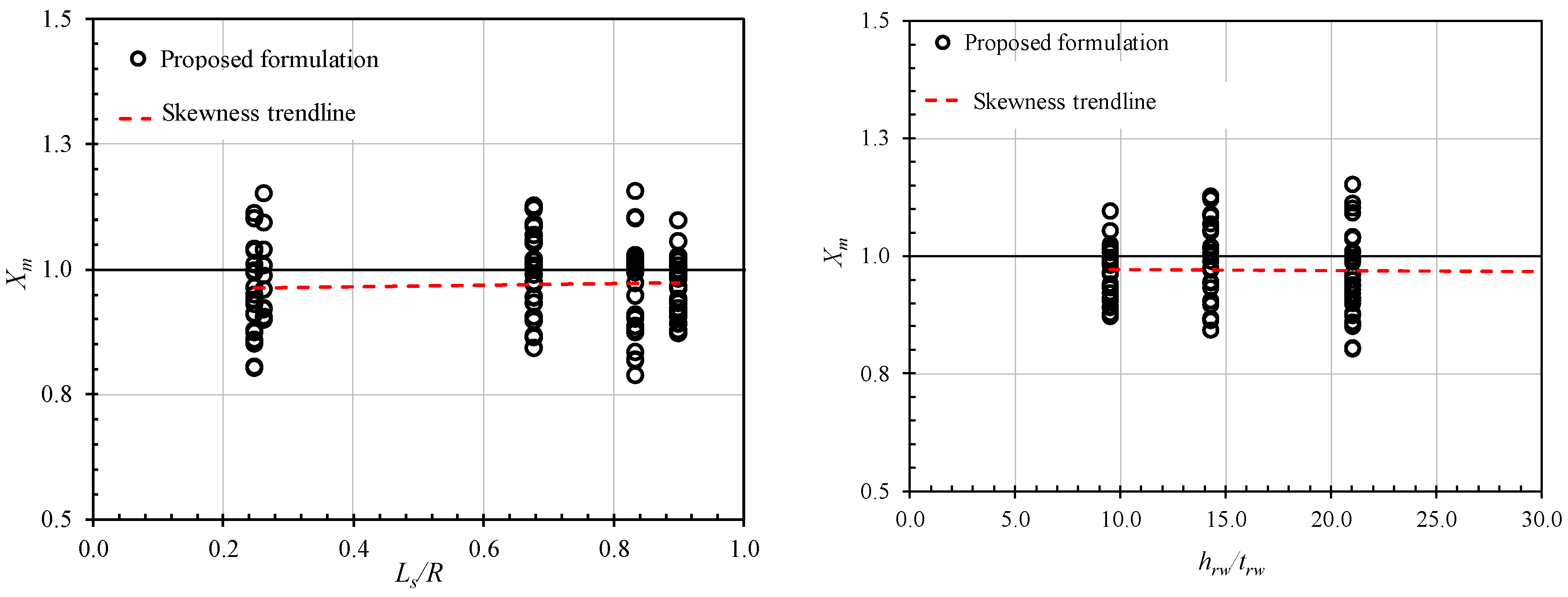
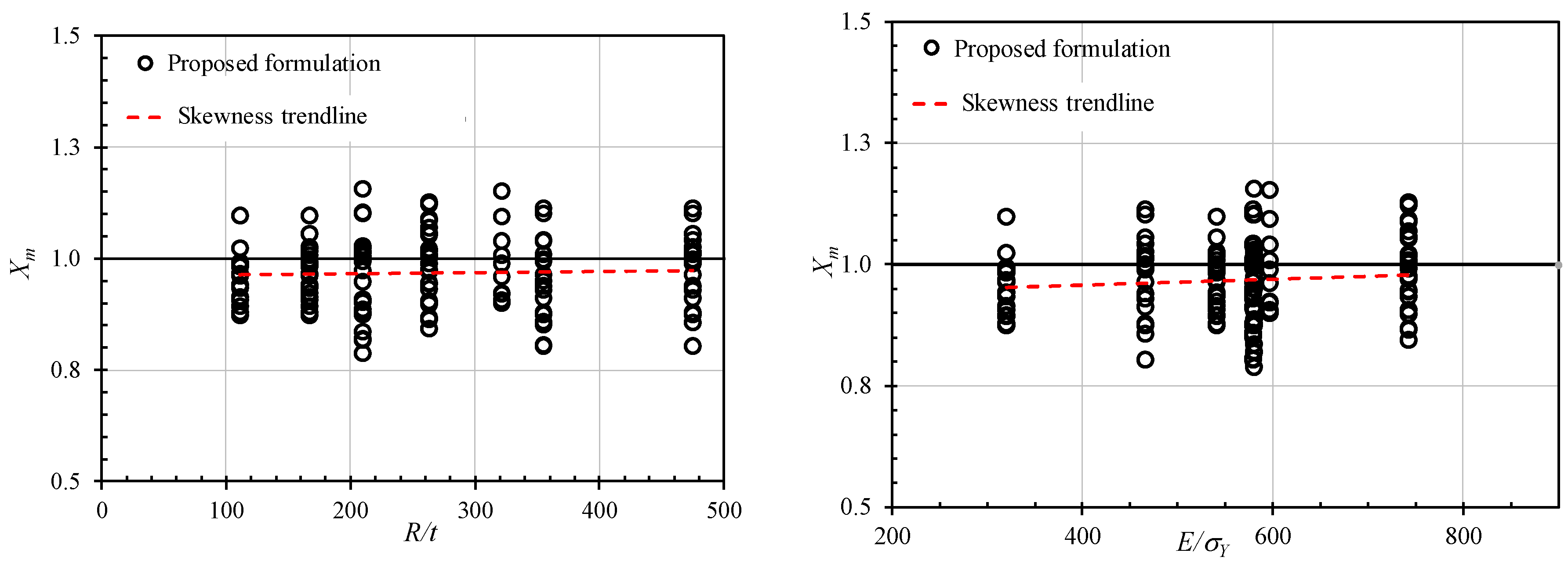
The skewness of the proposed formulation results to the numerical analysis results (
Xm) with various parameters is plotted in
Figure 25,
Figure 26 and
Figure 27. There is no apparent skewness in these figures. Therefore, these basic parameters should be not considered for inclusion in the design of the proposed formulation to predict the maximum permanent dent depth of the stringer-stiffened cylinder under dynamic mass impact.
5. Accuracy of the Proposed Formulation
To validate the accuracy and reliability of the proposed formulation for the extent damage predictions of the ring- and/or stringer-stiffened cylinders, the comparisons between the proposed formulation and the available test results and the existing analytical equations in the literature were conducted.
5.1. Comparison with Available Test Results
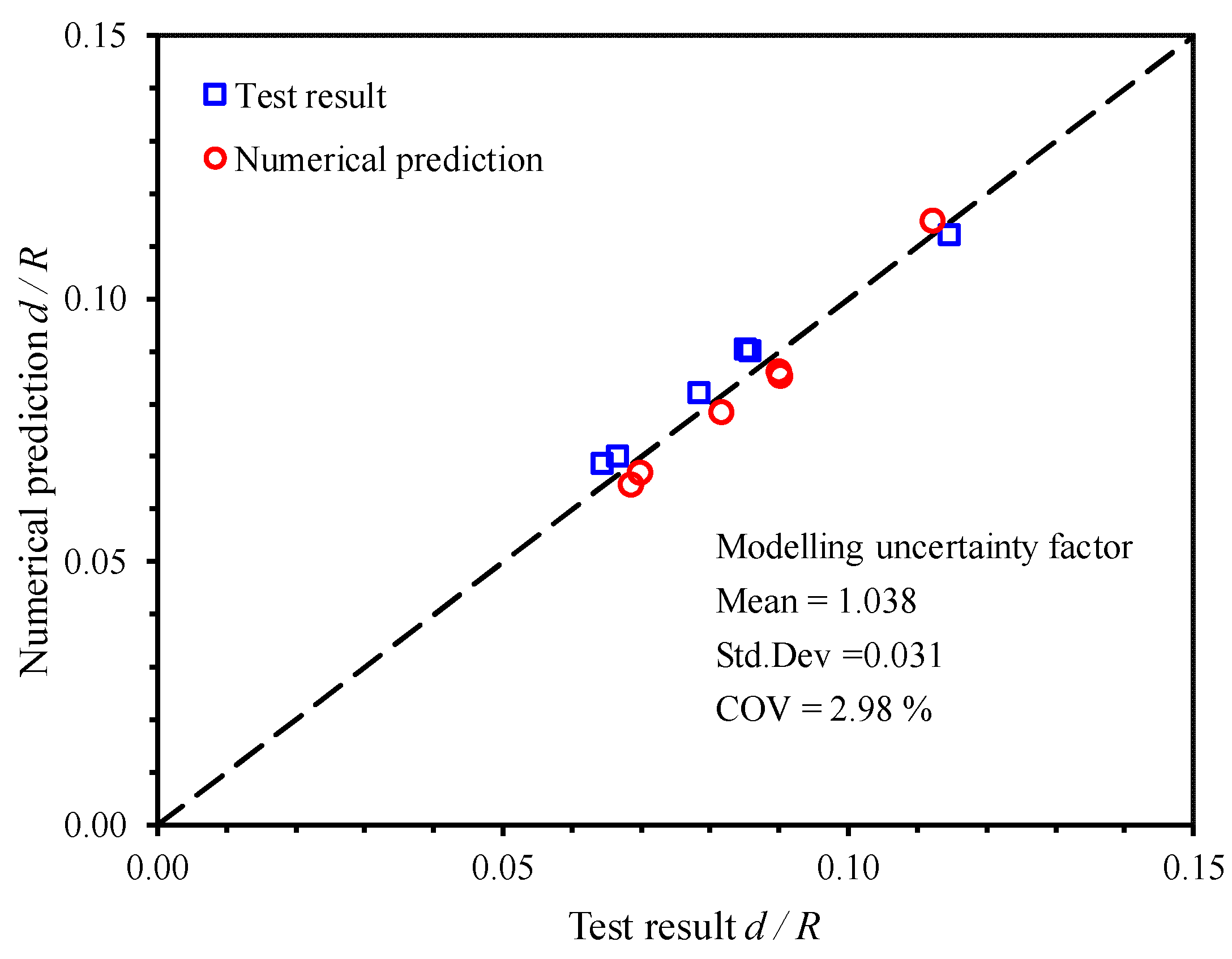
A comparison of the proposed formulation predictions and available experimental results is summarized in
Table 9. The bias (proposed formulation values/test values) was smaller than 8.1% for all cases. Furthermore, the mean of
Xm for all the models was 1.040 together with a COV of 2.74%. This means that the proposed formulation provides a good accuracy for the predicting of maximum local dent depth of stiffened cylinder structures under dynamic mass impact. Therefore, in actual cases, when the striking mass, impact velocity, and geometry of the cylinder structures and material properties were provided, the maximum permanent local dent depth was quickly predicted by using the proposed formulations, (Equation (15) for ring-stiffened cylinders and Equation (26) for stringer-stiffened cylinders, respectively).
5.2. Comparison with Other Existing Formulae
Prior to comparing the newly derived formulation with other formulations, let us re-visit the existing equations in the open literature for predicting the permanent dent depth of stiffened cylinders. The equations by Hoo Fatt and Wierzbicki [
13], provided the smeared model based on the equivalent thickness. However, the shortcoming were that the membrane resistances of cylinder shell increased significantly when the thickness and fully plastic moment of the cylinder shell were replaced with the equivalent thickness and equivalent bending moment per length, respectively. The force-displacement relation is then expressed as Equation (31):
where
m0: fully plastic bending moment of the cylinder wall per unit length; ,
d: permanent dent depth at the impact point,
σ0: average flow stress; , and
teq: equivalent thickness; .
Equation (31) was improved by Cerik et al. [
2]. He followed the assumption of Hoo Fatt and Wierzbicki [
13], but only
m0 was replaced with
meq. The force-displacement response for the ring-stiffened cylinder is obtained as Equation (32):
where
meq: equivalent bending moment per length; ,
M: bending moment; lr: ring-stiffener spacing, and
N0: plastic axial resistance per unit width; N0 = σ0t.
Unlike the case of ring-stiffeners, the stringer affects both membrane resistance and circumferential bending resistance. Thus, the stringers were smeared to obtain an equivalent shell thickness and then the stringers were treated as beams and adding the resistance of each stringer was added to the resistance of the cylinder shell. The force-displacement response for stringer-stiffened cylinder is obtained as Equation (33):
where
w: beam deflection; hsw: stringer web height,
ns: number of stringers in damaged effect zone,
P0: plastic collapse resistance in bending; ,
Mp and L are plastic bending moment and total length of the stringer-stiffener, respectively;
Ptotal: resistance of the stringer-stiffened cylinder, and
Pcyl: resistance of the cylinder shell.
In the current study, the force-displacement relationship for both ring and stringer-stiffened cylinders can be expressed as the following equations:
In the current study, the force-displacement response of the proposed formulation is expressed in Equations (34) and (35) for mean equation and characteristic equation, respectively. It can be obtained by the derivation of Equations (15) and (16) with respect to
d.The force-displacement response of the proposed formulation is expressed in Equations (27) and (28) for mean equation and characteristic equation, respectively. It can be quickly achieved by the derivation of Equations (36) and (37) with respect to
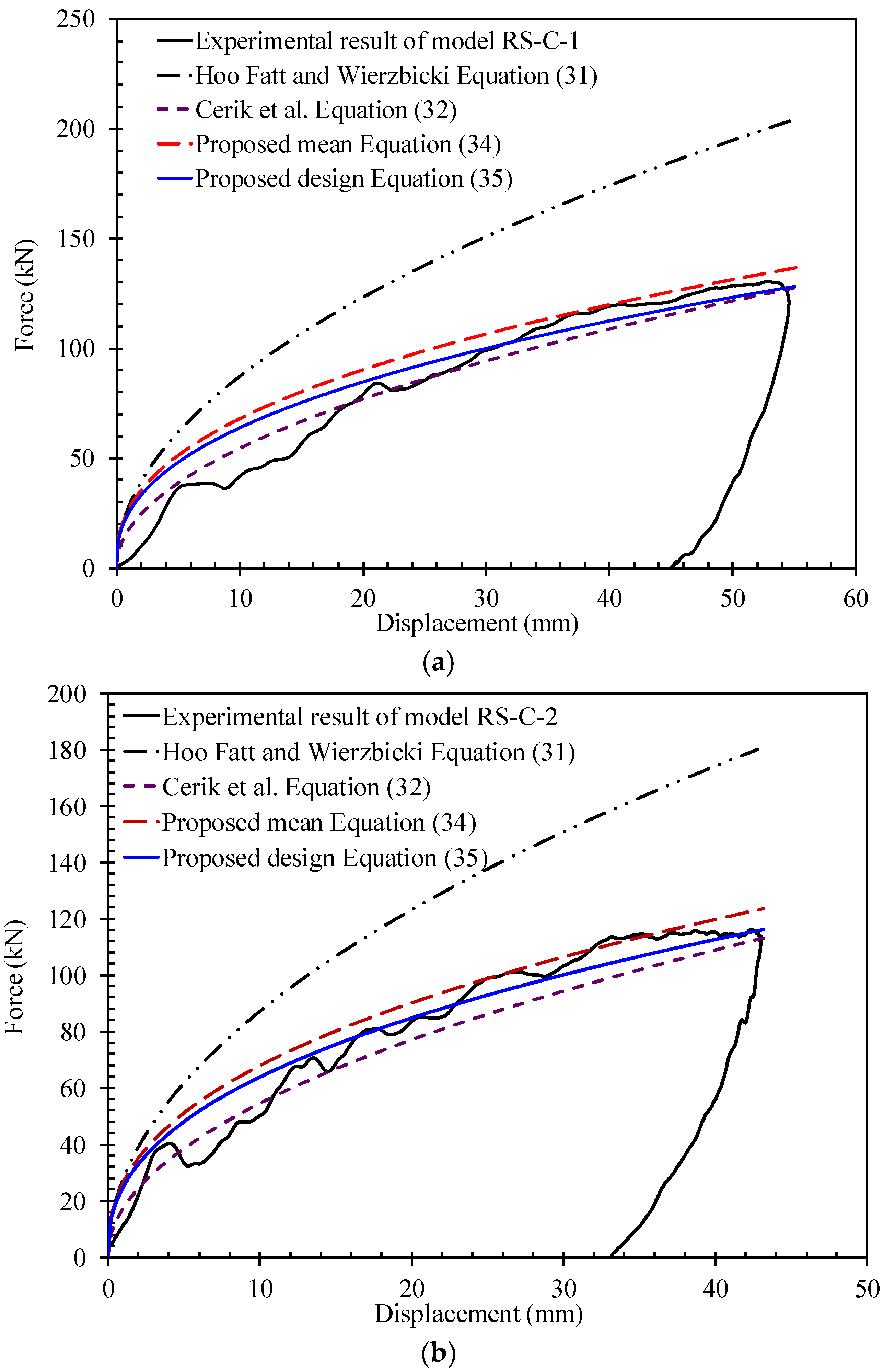
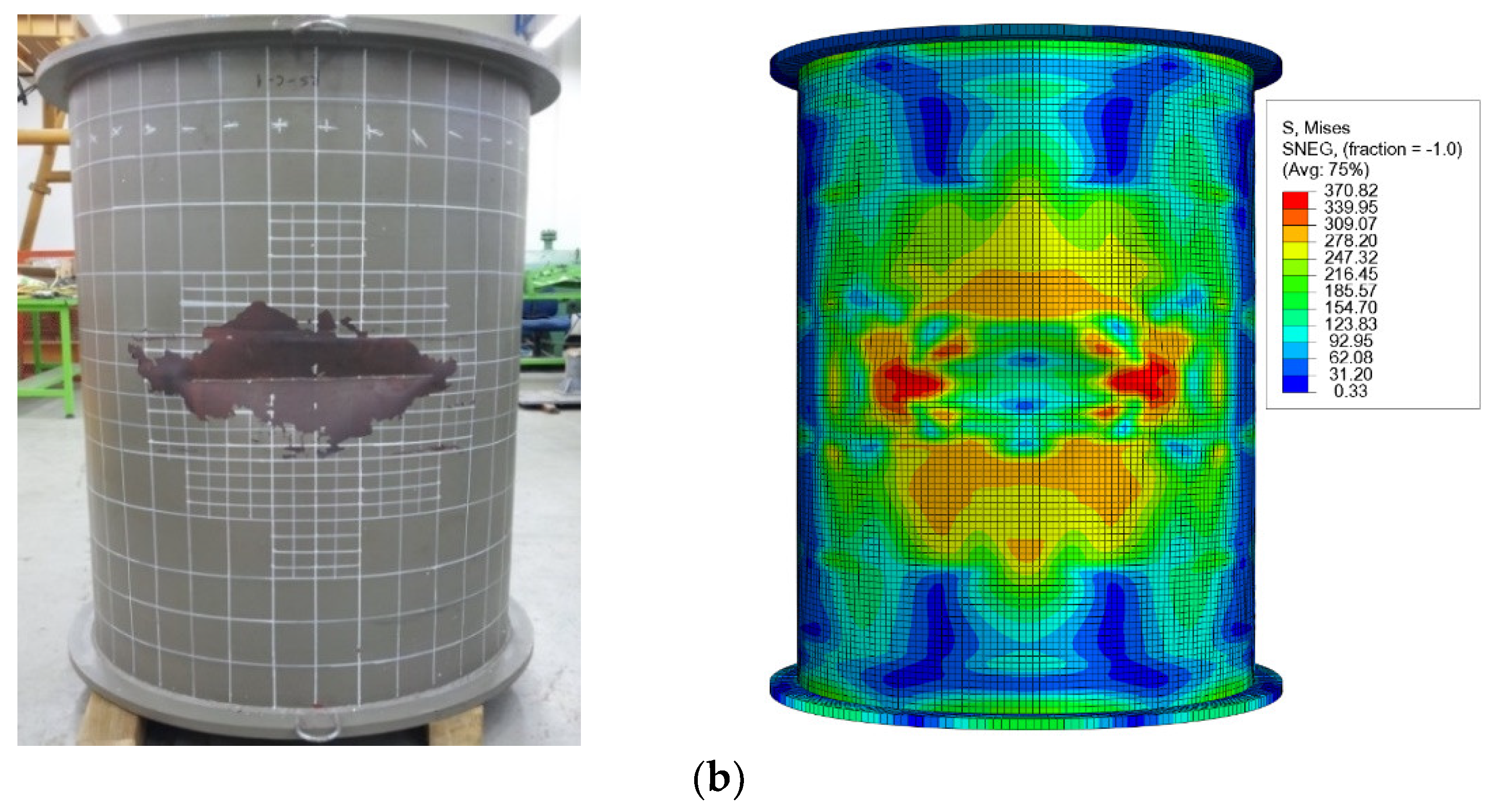
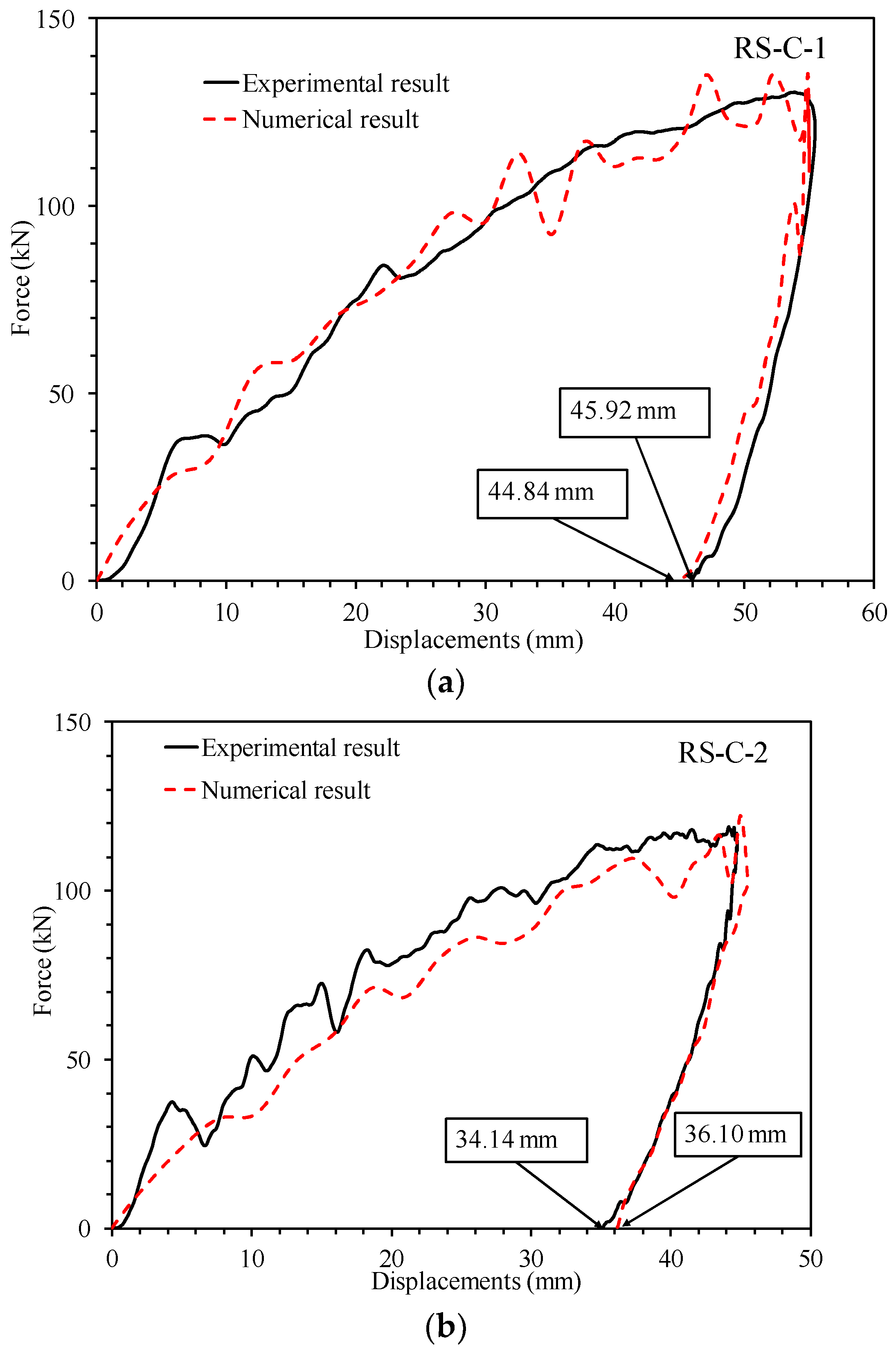
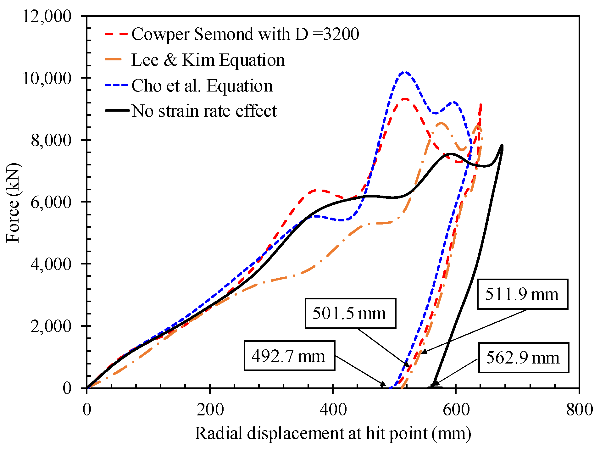
d.The force-displacement responses obtained using proposed formulations were compared with that of the experimental results and other existing equations to assess the validity of the approach and any shortcomings, as illustrated in
Figure 28. The proposed formulation from Fatt and Wierzbicki (1991) is highly over-predicted, while that of Cerik et al. (2015) equation is under-predicted with experimental results. However, the initial part of the Cerik curve matched well with the test results. For the force-displacement response curve of the proposed formulation, when Equation (15) was equated to the impact energy in the experimental result, maximum dent depth at peak force can be obtained. In comparison with the force-displacement values, it predicted well with experimental results for the proposed mean Equation (34). When considering the safety design in risk conditions, the proposed design Equation (35) was under predicted.
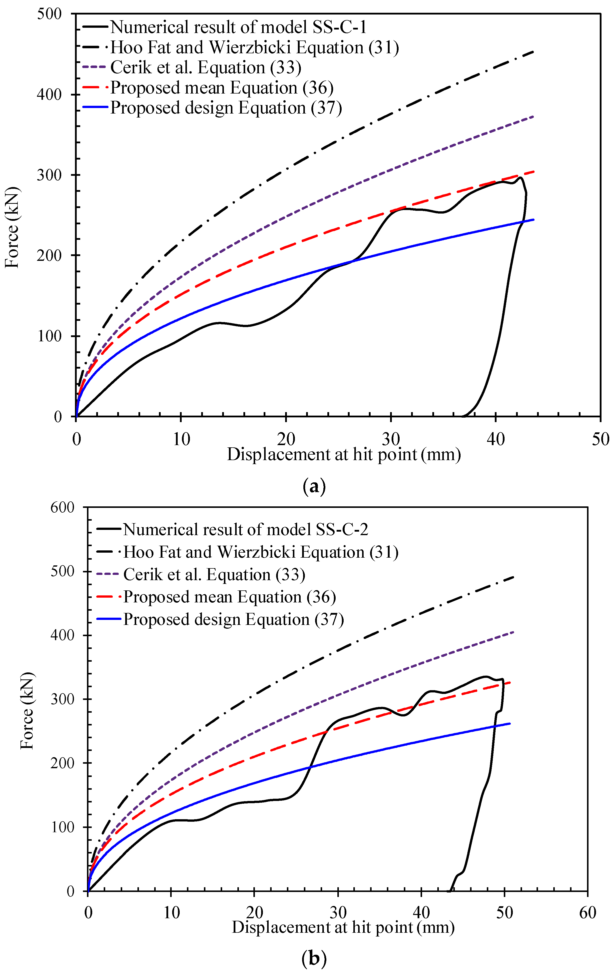
The proposed formulations were compared with the numerical results and existing formulae of the two stringer-stiffened cylinder models (SS-C-1 and SS-C-2), as shown in
Figure 29. It is noted that the fluctuations in numerical results could not be captured for all models. Further, the initial resistance, which is the collapse resistance of the first stringer and attached plating, was a bit higher in the numerical results. This should be attributed to the strain rate effect and vibration during impact processes. Nevertheless, the overall tendencies of the numerical response are well captured by both models. It is clear that force-displacement relations of Hoo Fatt and Wierzbicki (1991) and Cerik et al. (2015) is over-predicted. However, the proposed formulation predicted well. The main difference of the proposed formulation was that the slope of the force-displacement curve did not decrease much as in the existing formulae. It is believed that for a simple tool this inaccuracy is acceptable. This is important when designing the stringer-stiffened cylinder based on strength design principles.

 ,
, 


