Abstract
The present paper proposes an approach for the development of a non-linear model-based predictive controller (NMPC) using a non-linear process model based on Artificial Neural Networks (ANNs). This work exploits recent trends on ANN literature using a TensorFlow implementation and shows how they can be efficiently used as support for closed-loop control systems. Furthermore, it evaluates how the generalization capability problems of neural networks can be efficiently overcome when the model that supports the control algorithm is used outside of its initial training conditions. The process’s transient response performance and steady-state error are parameters under focus and will be evaluated using a MATLAB’s Simulink implementation of a Coupled Tank Liquid Level controller and a Yeast Fermentation Reaction Temperature controller, two well-known benchmark systems for non-linear control problems.
1. Introduction
Nowadays, control systems have an important role in the automation industry due to the increasingly tight requirements posed over precision, performance, efficiency, and safety metrics of automatic systems. Moreover, they become ubiquitously present in many aspects of our daily life such as in housing heating systems, household appliances, among many other “intelligent” products that we rely on every day. While this “intelligence” is still far from accomplishing the same challenges humans can, the closed coupling between advanced control algorithms and good domain-specific process models has significantly expanded the application scenarios of autonomous computational systems. Model Predictive Control algorithms and the TensorFlow variant of Artificial Neural Networks (ANN) have many proven concepts and advantages in their specific areas of application (control and system modeling respectively) but, up to the author’s best knowledge have not been used in synergy.
Model-based Predictive Control (MPC) is considered as an advanced technique of control and it is widely used in several industrial applications [1]. The concept of MPC does not refer to a specific control strategy. Instead, it is a set of control techniques (such as Dynamic Matrix Control (DMC) [2] and Generalized Predictive Control [3]) which makes use of a system’s model to calculate the control actions over a time horizon by minimizing a cost function. Thus, the core of the MPC strategy is the mathematical model which describes the dynamics of the system to be controlled. MPC is a computationally expensive and time-consuming algorithm [4] which in the case of low-resource systems imposes a challenge. Because of that, it was firstly used in systems with slow dynamics [5,6], due to its compatibility with the required control rate.
Due to the tremendous technological evolution, computer processing units have become much faster allowing a larger number of operations per second, which facilitated using the MPC algorithm in more demanding systems. For example, Mohanty [7] proposes an MPC controller to control a flotation column while other works use MPC controllers for systems with faster dynamics [8,9].
On the other side, machine learning has been applied successfully in different research fields such as image classification [10], speech recognition [11], natural language processing [12] and system behavior prediction [13] due to its capability to build models that can learn non-linear mappings from data. ANNs cover a small subset of machine learning implementations being some of them openly debated and freely available to foster science advancement. Some examples of machine learning frameworks that have been gathering a great amount of interest from the community are TensorFlow [14], Keras [15], Caffe [16] while Ensmallen [17] has provided efficient mathematical optimization methods supporting the referred frameworks. More recently, new opportunities for machine learning are emerging in the domains of small portable devices using the Tensor Flow Lite implementation [18] and even in embedded systems and other devices with only kilobytes of memory using ported versions of Tensor Flow Lite implementation such as TinyML [19] or CMSIS-NN [20].
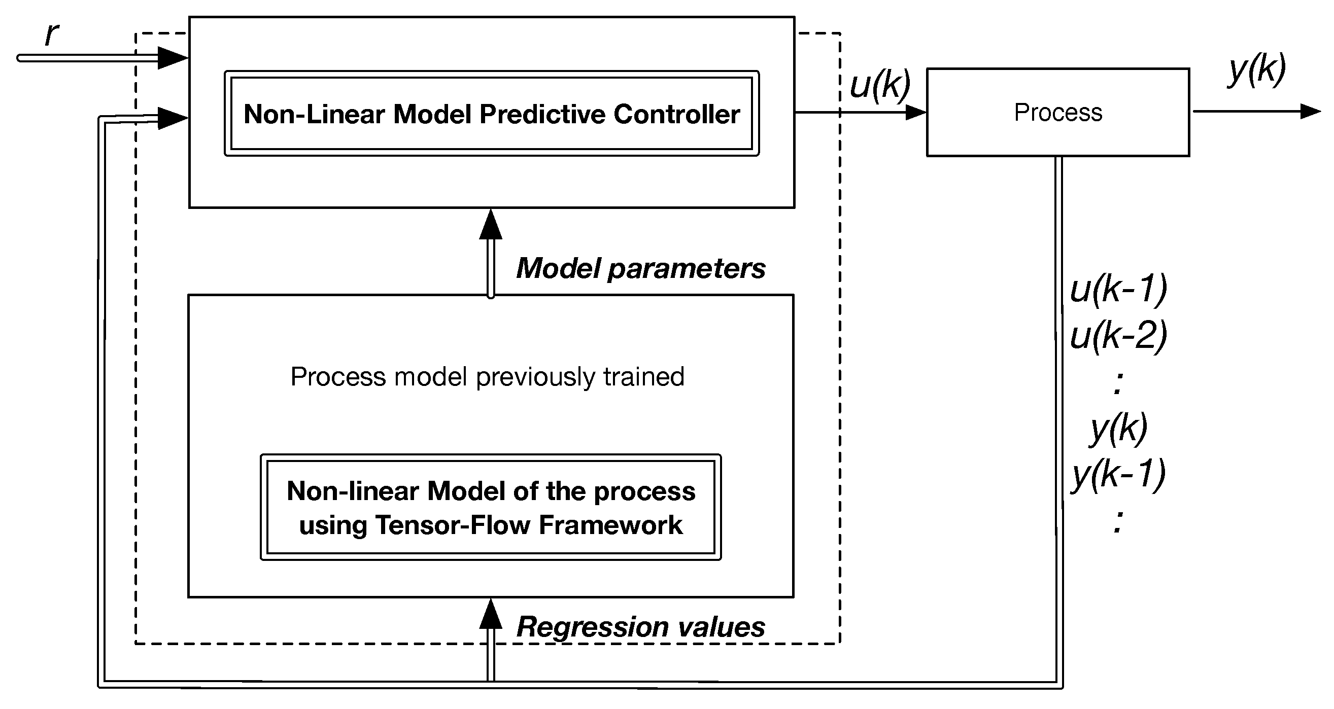
In this work it is used a framework created by Raymond Phan (https://github.com/rayryeng), NeuralNetPlayground [21], inspired by the TensorFlow Neural Networks Playground interface, to build small deep learning systems in Matlab for regression and classification of non-linear data applications. These models, based on neural network structures, are trained during an initial open loop actuation of a non-linear process to learn its relevant dynamic features. After the model extraction procedure, they are integrated in an indirect closed loop controller synthesis procedure in order to manipulate the process according to a set of required operation conditions. The control law implementation follows the MPC principles, which optimizes the control actions within a prediction horizon. The methodology is evaluated against a Coupled Tank Liquid Level control problem and a Yeast Fermentation Reaction Temperature control problem, as two non-linear benchmark scenarios. The system architecture of the proposed solution is depicted in Figure 1.
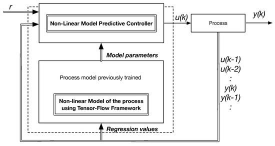
Figure 1.
System Architecture for the implementation of a Tensor Flow model-based control system.
2. Developing a System Model with Tensor Flow
A successful identification of a process’s discrete model is a task highly dependent on the choice of its structure and number of variables. This task becomes even more challenging when it is necessary to employ non-linear models to approximate the system’s input/output behavior. In the present work, it is used an ANN based on the TensorFlow implementation, using a regression variable’s vector according to the Auto-Regressive model with eXogenous inputs (ARX) linear model structure—an approach referred in literature as Neural Network Auto-Regressive with eXogenous inputs (NNARX) [22]. The ANN is organized as a Multilayer Perceptron (MLP), an architecture known to be a proper choice for black-box modeling and system identification due to its scalability and universal approximator capability.
Regarding model structure, we set the activation functions of the hidden layer nodes to be hyperbolic tangent and in the output node as a linear activation function. This setup enables a good balance between model dimensionality and fitness of the model to non-linear systems. In what concerns to the parameters tunning, this procedure is accomplished through the execution of an optimization problem. Optimization is the task of minimizing or maximizing a cost function by varying x. When training neural networks, it is frequently to use the mean squared error as cost function, as defined by J in Equation (1), and our goal is to find the set of parameters that minimize its value:
where N is the number of samples, is the set of data containing the inputs, is the expected output, is the output calculated by the ANN, W is a vector of all ANN weights and is the regularization parameter that penalizes weights with high values. This parameter must be a positive value and its magnitude must be selected so it does not become the driving factor of the cost function as the main objective is to minimize the error between the training data set and the output generated by the neural network.
The gradient descent is often the chosen iterative optimization algorithm to find a non-linear function minimum [23]. However, one of the disadvantages of this method is that it becomes time-consuming if the data set is large and the network has multiple internal layers. Nevertheless, to have an ANN with good generalization, a huge amount of data is required making the training a heavy task. To overcome this limitation, the Stochastic Gradient Descent (SGD) was developed as an extension of the gradient descent [24], in which the main difference is that instead of using all the samples available in the training data set, it uses only a smaller portion of this data in each step of the algorithm, making the training faster. This mini-batch of samples are drawn uniformly from the training data set. We use the SGD algorithm to train our neural network.
3. Benchmark Models
To assess the control strategy to be presented, two non-linear processes will be used. The Fermentation Reactor [25] and the Coupled Tanks systems [26] are two classical benchmark frameworks frequently used in the literature to evaluate the performance and robustness of non-linear modeling and control methodologies.
3.1. Coupled Tanks System
In several industry processes, it is often required to process liquids within storage devices. Many times, they are solely pumped across reservoirs but can also be part of chemical reactions where sudden volumetric changes can happen. Anyhow, in any scenario, the level of a fluid within a storage tank must be controlled according to its capacity limits.
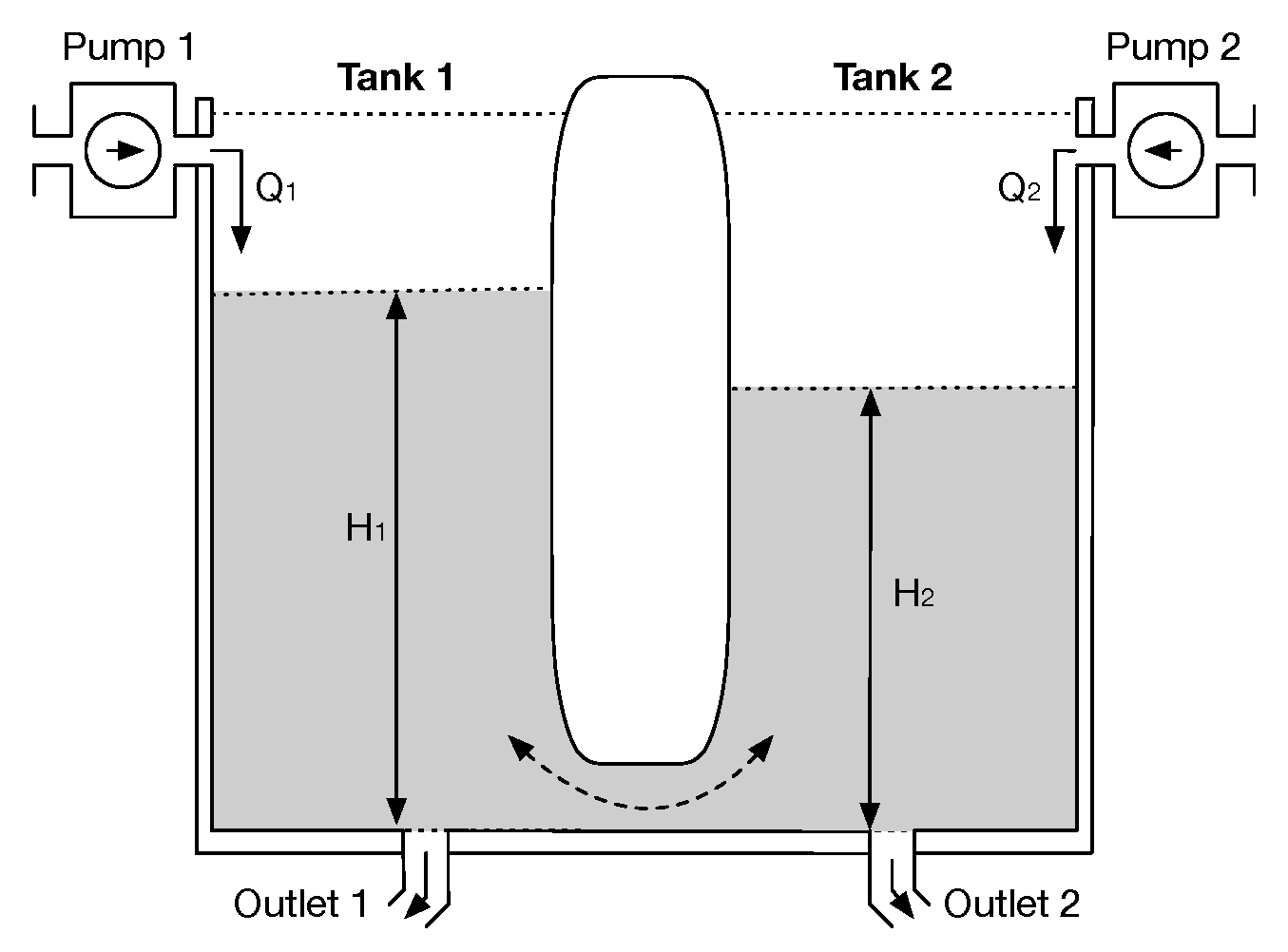
In the present scenario, a system consisting of two tanks is used, having each one an independent pump to control the inflow of liquid ( and ) and an outlet at the bottom responsible for the liquid leakage. The tanks are interconnected by a channel which allows the liquid to flow between them and the variables under control are the liquid heights in each tank ( and ) [27], as depicted in Figure 2,
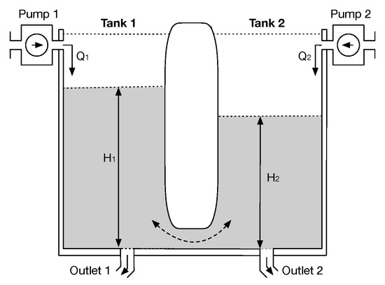
Figure 2.
Diagram of the coupled tanks system. Adapted from [27].
The dynamic of this system can be described by the set of non-linear differential Equations (2) and (3) [27].
where and denote the cross-sectional area of the tank 1 and 2, and are the liquid level in tank 1 and 2, and are the volumetric flow rate (cm s) of Pump 1 and 2, , and are proportionality coefficient corresponding to the , and terms which depend on the discharge coefficients of each outlet and the gravitational constant. In the present evaluation, will be used as an unmeasured external disturbance for the control system. The reservoir model parameters were obtained from the setup described in [28], and are presented in Table 1:

Table 1.
Parameters of the simulated Coupled Tanks System.
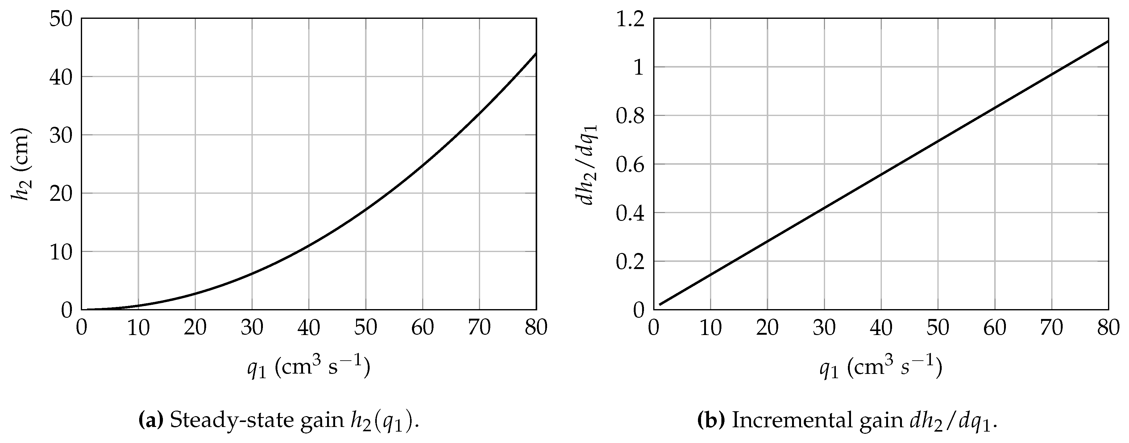
As evidenced by Figure 3a,b the system’s steady-state gain is of non-linear nature and its incremental gain highly dependent on the current operation point.
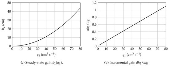
Figure 3.
Steady-state gain and incremental gain variation in the Coupled Tanks Liquid Level Control problem.
3.2. Yeast Fermentation Reaction
Yeast fermentation is a biochemical process which, having ethanol and carbon-dioxide as a sub-product, has significant value for several branches of food industry as well for other domains such as pharmaceutical and chemical. The yeast fermentation reaction is itself a composition of several interdependent physical/chemical processes occurring simultaneously which occur within a reactor. This reactor if often modelled as a stirred tank with constant substrate feed flow and a constant outlet flow containing the product (ethanol), substrate (glucose), and biomass (suspension of yeast). Given its large structure and number of parameters, the details of the model are not hereby presented and can be found in [29].
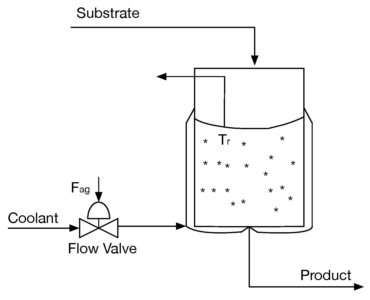
Fermentation reactions are of an exothermic nature and, since they are dependent on living organisms whose growth rate is highly sensitive to temperature variations, it is important to avoid temperature runaway of the reactor. Driven by this, temperature control is a key factor to ensure the reaction stability, and, for that purpose, cooling jackets are often employed [30]. Thus, from the perspective of a control algorithm, the reactor is a single-input single-output process: the coolant flow rate () is the input (the manipulated variable) and the reactor’s temperature () is the output (the controlled variable). In the present evaluation, the substrate temperature will act as an external disturbance to the system. The continuous fermentation reactor that will serve as an evaluation scenario for the developed control strategy is depicted in Figure 4.
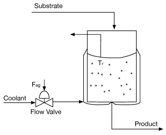
Figure 4.
Setup of the continuous fermentation reactor.
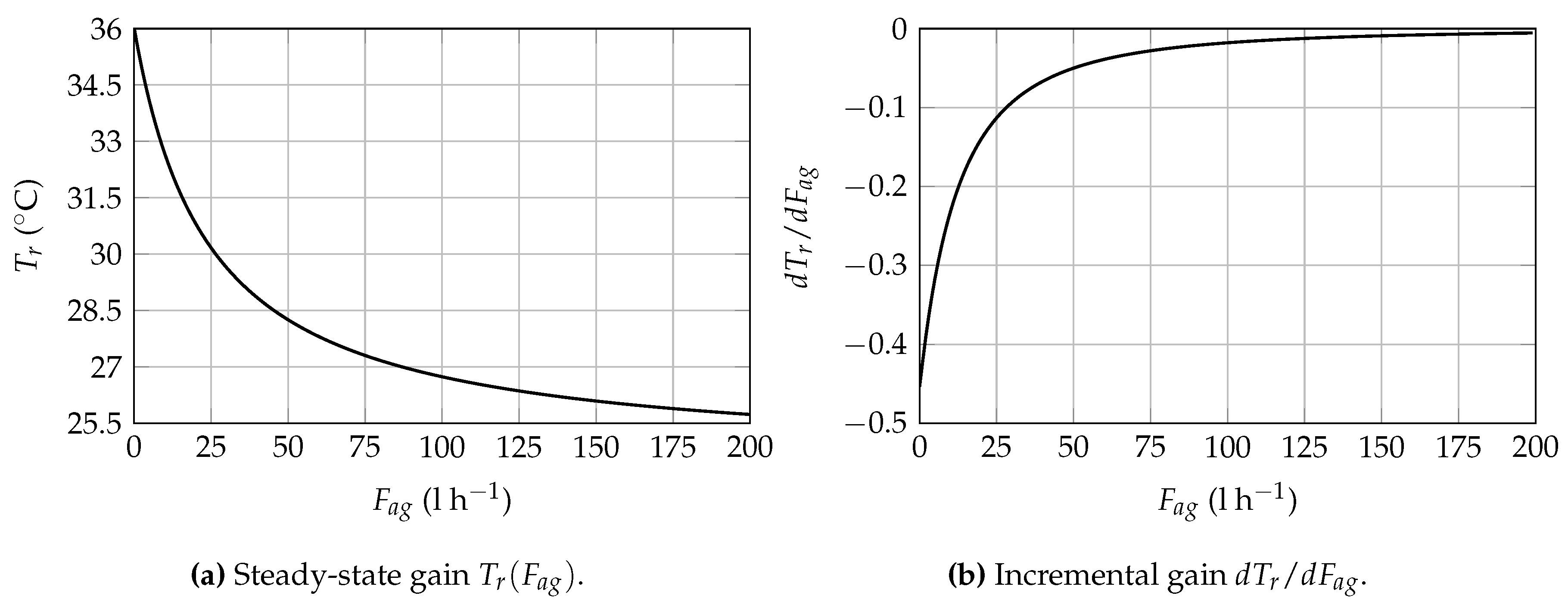
The dynamic behavior of the process is of non-linear nature and highly dependent on the current operation point, as evinced by the the steady-state gain curve, depicted in Figure 5a) and the incremental gain represented in Figure 5b.
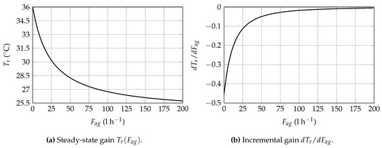
Figure 5.
Steady-state gain and Incremental gain variation in the Yeast Fermentation Reaction Temperature Control problem.
4. Process Identification
System identification is the task of mathematically describe a model of a dynamic system through a set of measurements made to the real system (black-box modeling).
System identification can be divided in four steps as described by Nørgaard et al. [22]: (i) experiment, (ii) model structure selection, (iii) model estimation, and (iv) model validation. Details about these steps follow.
4.1. Experiment
This is the first step being one of the most important in system identification. Open loop tests are made to gain insights about the system and gather the data that describes the system behavior. There are some choices that need to be done carefully such as the sampling frequency and the input signal that must excite the system over its entire operating range.
In the Coupled Tanks Liquid Level control scenario, by evaluating the system response to several step actuations over the flow rate of pump 1, a sampling interval of 2 seconds was chosen as appropriate to capture the plant’s behavior. Regarding the Yeast Fermentation Reactor Temperature control scenario, this process has a relatively slow dynamic behavior which is mainly imposed by the glucose decomposition rate [29]. Consequently, when the reaction’s operation point is changed, the attained settling time is in the scale of hours and, as so, one sample per hour is enough to capture the process’s relevant dynamics.
For the analysis of both models, train and test sets were created with 20 thousand samples each. This data collection is made using MATLAB, choosing a pseudo-random input signal to manipulate the system.
4.2. Model Structure Selection
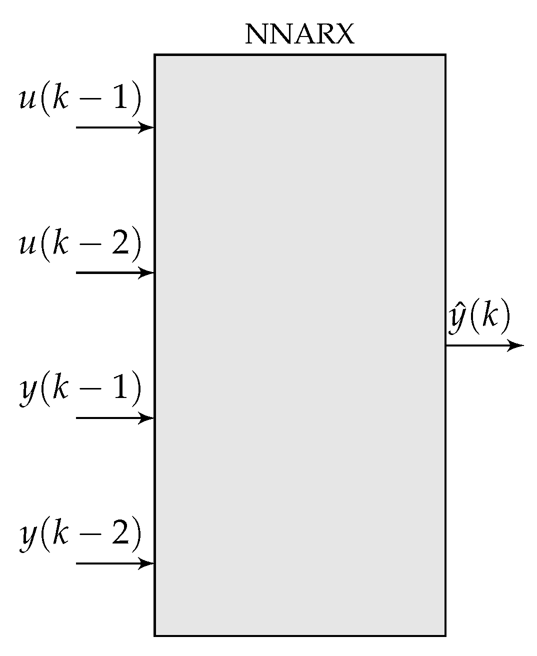
One important step for the model identification procedure is the definition of its structure. Regarding the coupled tanks system, as it presents two storage tanks it can be approximated as a second order system. Therefore we use an NNARX model with two past output signals, and , and two past input signals, and , where the output relates to the height of tank 2 () and the input is the flow rate of pump 1 (). Though, other structures, as reported by Nørgaard et al. [22], could be adopted.
In what concerns the Fermentation Reactor modeling, on related literature [25] second-order regressive models with no dead-time are found to be adequate for this task. Once again, we can use an NNARX model with two past output signals, and , and two past input signals, and , where the output relates to the reactor internal temperature and the input is the coolant flow rate .
The structure of both models is generically depicted Figure 6.
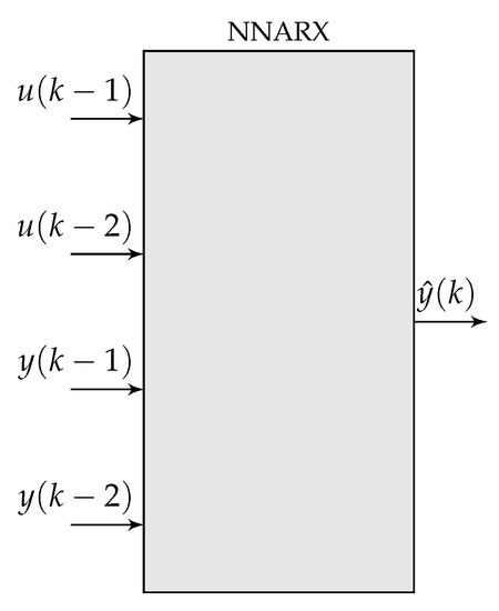
Figure 6.
NNARX model structure.
4.3. Model Estimation
With the chosen structure and using the gathered data, , the next step is to train the neural network. This process starts by randomly initializing the weights, and then updating them with the SGD method.
The model training framework allows one to specify several input parameters such as number of hidden layers, number of neurons in each layer, learning rate (), regularization factor (), epochs and mini-batch size, defined in Table 2. Several neural networks with two hidden layers and different number of neurons (5, 8, and 10 neurons) were trained individually.

Table 2.
Parameters used in the model training framework.
4.4. Model Validation
In this final step, the trained model is evaluated to assess if it can properly represent the system behavior. As these models are biased to achieve good performance in the trained data set, they are further validated against a different test data set. For each model, its estimation Mean Squared Error (MSE) is measured using the test data set evaluation. The neural network that has the lowest MSE is then chosen to be the system predictor used by the MPC controller.
4.5. Results
In Table 3 and Table 4 are presented the MSE of both train and test data sets, for the differently trained neural networks.

Table 3.
Mean Squared Error of the Coupled Tanks Liquid Level model for several modeling approaches of with a different number of neurons and with two hidden layers.

Table 4.
Mean Squared Error of the Yeast Fermentation Reactor Temperature model for several modeling approaches of with a different number of neurons and with two hidden layers.
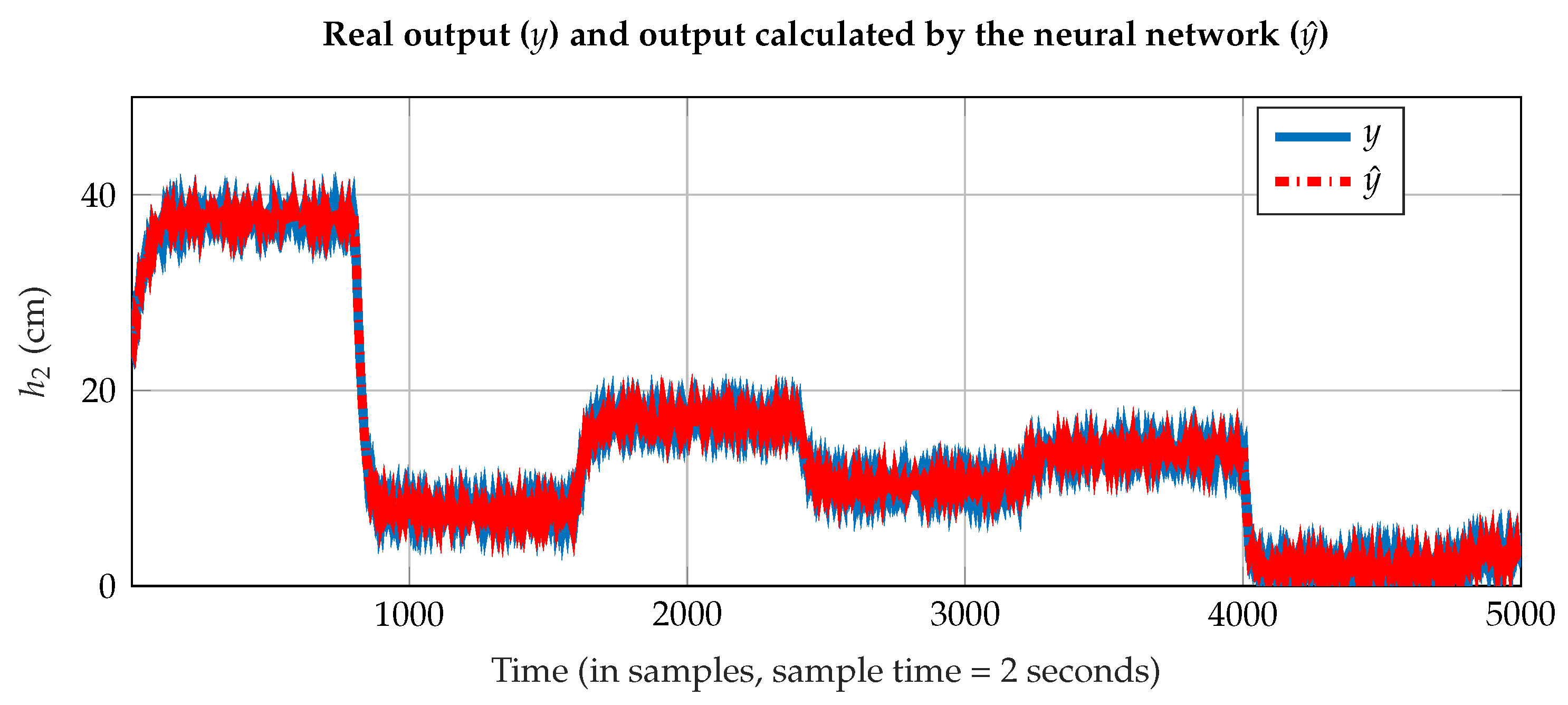
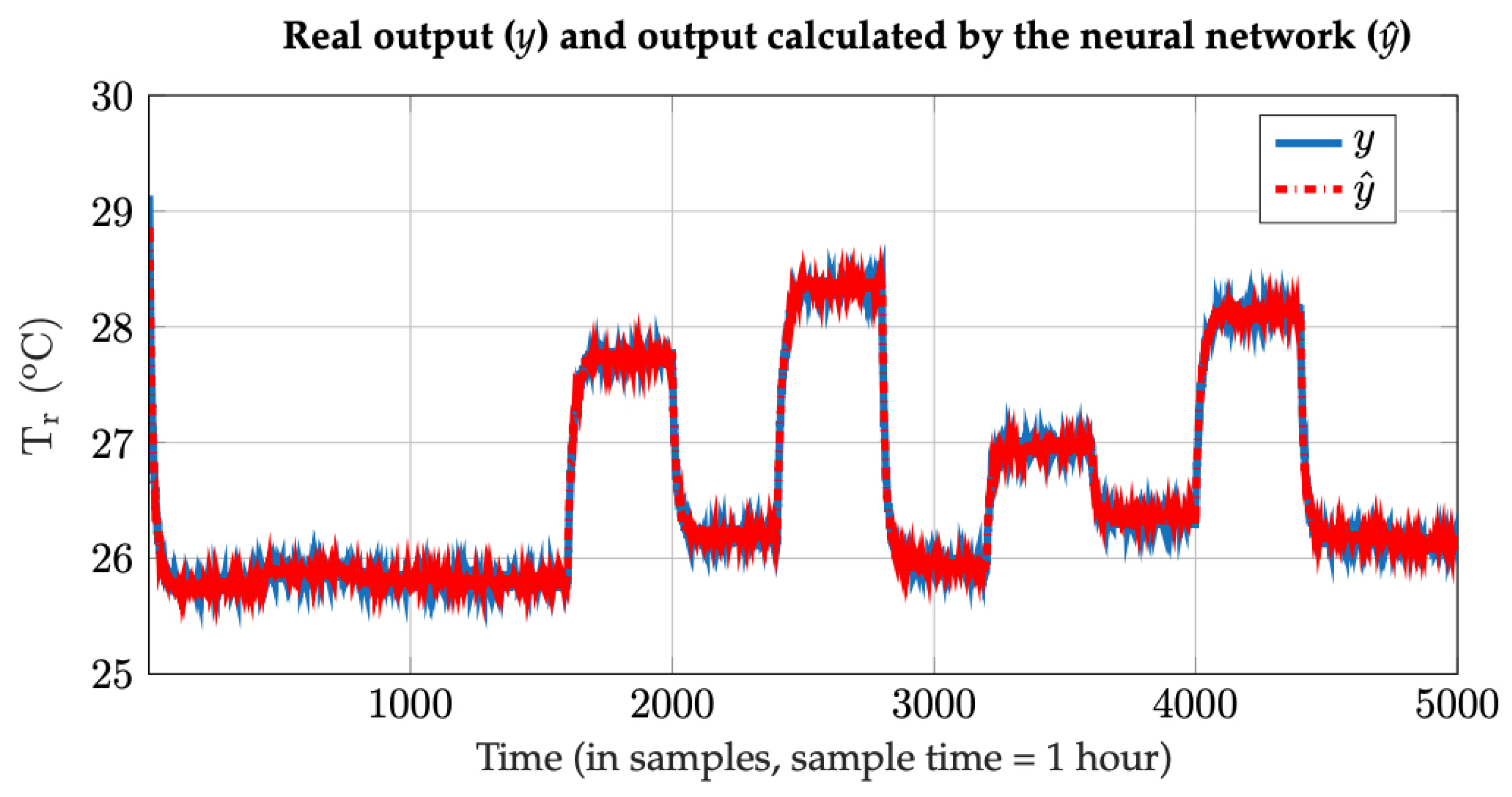
For the Coupled Tanks Liquid Level model, the lowest value in Table 3 occurs in the simulation number 6 with 10 neurons. In the Yeast Fermentation Reactor Temperature model case, the lowest value in Table 4 occurs in the simulation number 3 with 10 neurons. Figure 7 and Figure 8 depict the results for the “best” neural network, comparing the response calculated by the neural network and the real output for a given test data set. We verify that our procedure is capable of identifying a non-linear model of the system even when the measured signal is disturbed by noisy conditions. The remaining question is if the obtained models are suitable for control purposes.
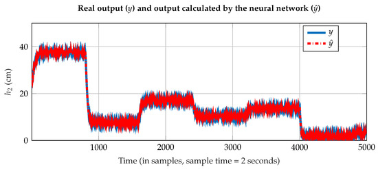
Figure 7.
Comparison between the real output (y) and the predicted output () by the neural network for the tank 2 liquid level.
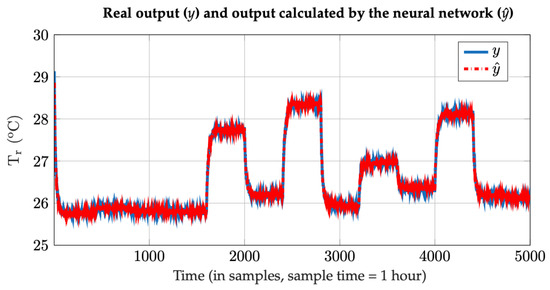
Figure 8.
Comparison between the real output (y) and the predicted output () by the neural network for the Yeast Fermentation Reactor Temperature.
5. Process Control
Control of non-linear systems is one of the many applications of neural networks, and its goal is to manipulate the system behavior in a pre-defined intended manner. The development of a controller-based in neural networks can be addressed in two ways: (i) direct methods, meaning that the neural network is trained as being the controller according to some criterion, and (ii) indirect methods, where the controller is based on the system model to be controlled (in this case the controller is not a neural network) [22]. In this work, we use an MPC which is an indirect method.
5.1. Model-Based Predictive Control
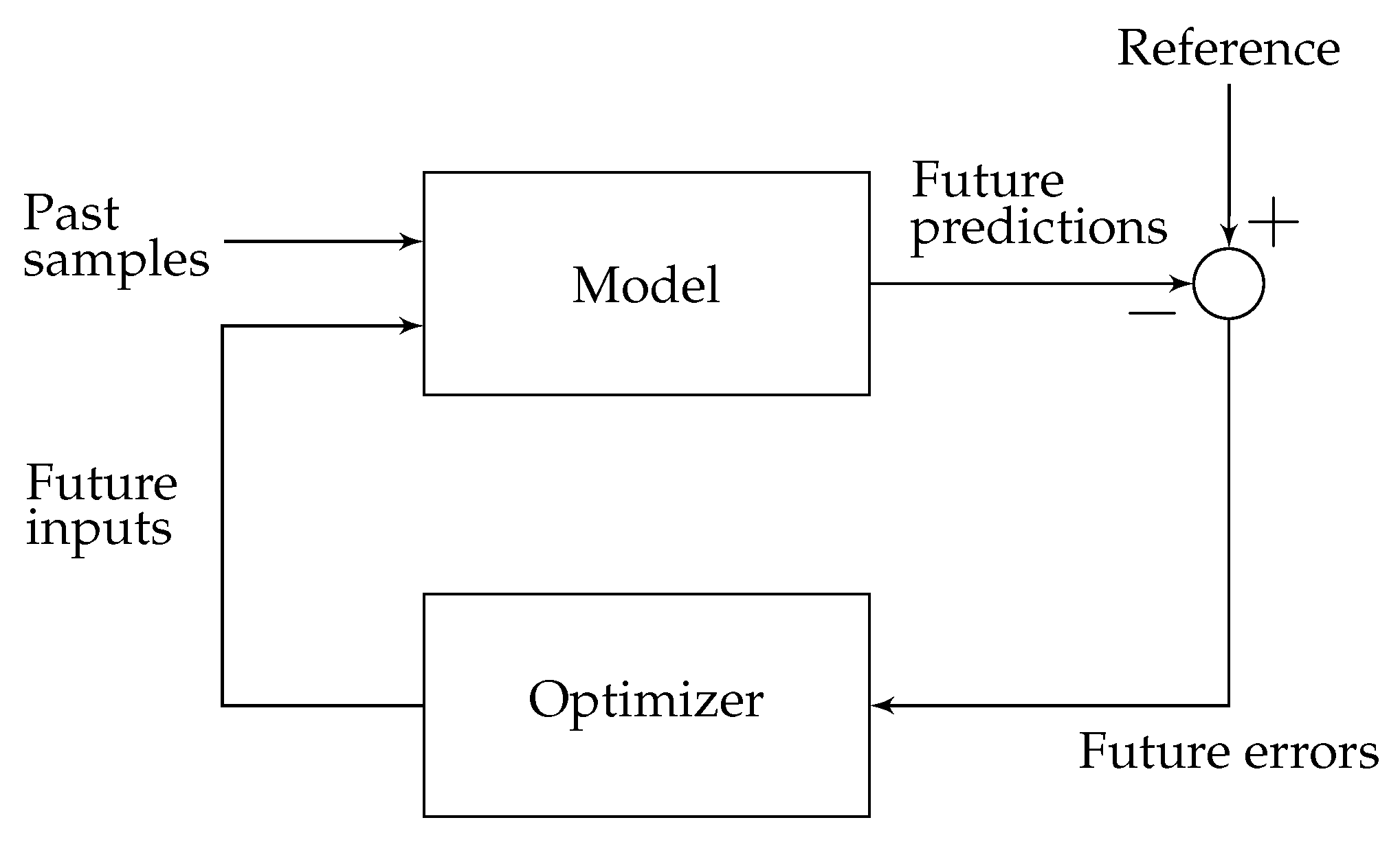
MPC is a control strategy that uses the model to predict the output. Using these predictions, the aim is to find the control signal that minimizes the cost function that is dependent on those predicted outputs, desired trajectories, and control actions. As these controllers depend on the system’s model, their performance heavily relies on the identified model. Figure 9 represents the basic structure of an MPC algorithm.
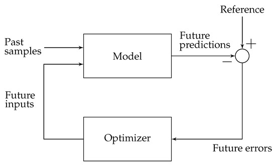
Figure 9.
Structure of MPC algorithm.
The idea of this approach is to minimize the criterion presented in (4).
Subject to:
with respect to the first future control inputs:
d is the time system delay (we assumed it equal to 1), is the signal with the future reference samples, is the signal with predicted output samples based on the model, is the signal with the changes in the control signal, is the minimum prediction horizon, is the prediction horizon, is the control horizon and is the weighting factor for penalizing changes is the control actions.
The minimization of this criterion, when the predictions are determined by a non-linear relationship, constitutes a complex non-linear programming problem. This problem draws more attention when real-time implementation is required as, under this condition, it is necessary to impose an upper bound to the control law sythnesis solution time. In this implementation, we use the Broyden-Fletcher-Goldfarb-Shanno (BFGS) algorithm to minimize the cost function (4) [23], implemented in the Brian Granzow’s (https://github.com/bgranzow) framework [31]. This is a quasi-Newton method that uses an approximation of the Hessian matrix to reduce the memory requirements of the optimization problem.
The MPC strategy can be summarized in the following steps [1]:
- The future outputs, , are calculated over the prediction horizon at each sampling time using the model of the system, which in this case is a neural network. These values of depend on the past input and output samples and the future control samples, .
- The values of are calculated by an optimization algorithm in order to minimize the cost function (4). This criterion tries to approximate the future outputs to the future reference signal.
- After optimization, the first sample of the signal is applied to the system and the other samples of this signal are ignored. When a new sampling time is available the described cycle starts over.
5.2. Disturbance Rejection
Besides accurately following a desired setpoint, a good controller must be able to react to unexpected external disturbances. This is a problem with control systems that are based on models as models of the distribution of disturbances introduce significant complexity for the control synthesis problem and are often limited in their validity. Therefore one must rely on other methods to deal with the external disturbances and model mismatches problems to avoid steady-state error in our control system [32].
In our model-based application, this problem we use an approach similar to Fatehi et al. [32]. In this work, it is suggested to add to to the future predictions, , a quantity representing the disturbance that it is assumed to be constant over the horizon:
where is the output of the neural network.
The parameter is the difference between the real output of the system and the output of the neural network, b and are weights that are adapted in each sampling time according to (10) and (11), respectively.
The constants and are chosen as: .
This scheme deals with the two problems mentioned above: (1) the model mismatches and (2) occurrence of external disturbances. Both cause prediction errors but must be treated separately. External perturbations need a faster adaptation to achieve fast variations on the system. When there are no external disturbances the adaptation should be slowed down because it may degrade the performance of prediction made by the model. According to Fatehi et al. [32], this is done by using a high-pass filter in the error signal .
6. Results
In this section, an analysis of the implemented closed-loop controller is made according to several operation scenarios. For each system, the effect of the controller design parameter weight on the transient response of the control system is made, the setpoint following capability is evaluated for several operation conditions and, finally the robustness of the control system to unmeasured external disturbances is evaluated.
6.1. Coupled Tanks Liquid Level Control
For this setup, the parameters of the MPC controller are presented in Table 5.

Table 5.
Parameters of the model-based predictive controller for the Coupled Tanks Liquid Level control.
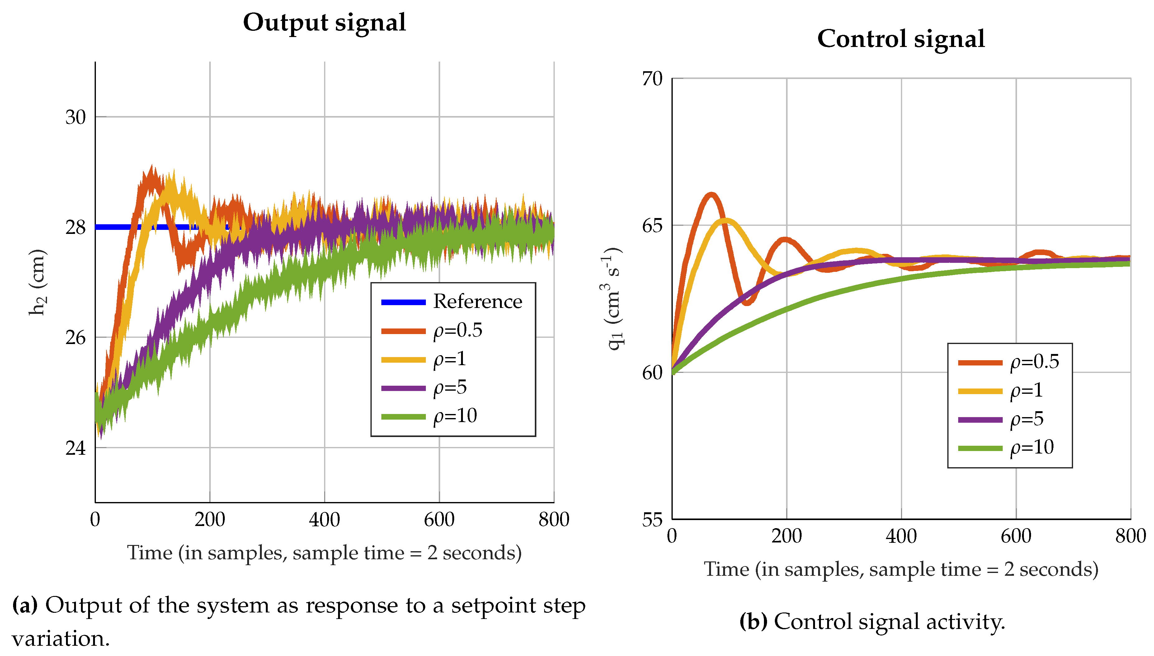
According to Figure 10a,b higher values of correspond to a smoother control signal and output signal while lower values of correspond to a more oscillatory control signal and output signal. This coefficient becomes a parameter of design depending on the project specification in terms of performance requirements such as settling time and overshoot.
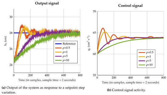
Figure 10.
Influence of the parameter (Control action attenuation factor) in the dynamic behavior of the control system.
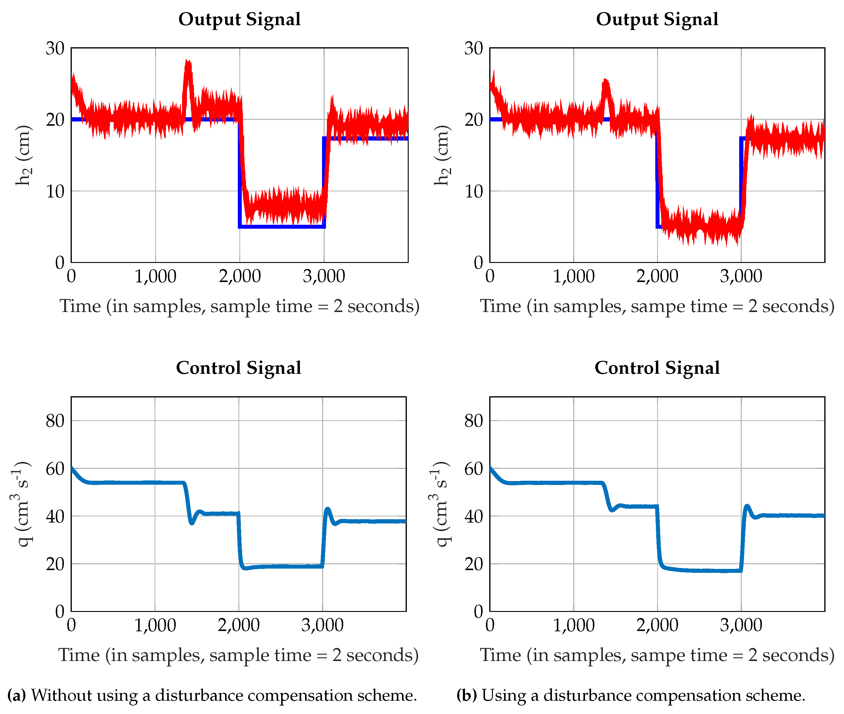
In Figure 11a,b is presented the closed loop performance of the control system in two distinct scenarios: firstly the strategy that compensates for the steady state error caused by external disturbances is not used whereas in the second case is. In both evaluations, the output signal is corrupted by Gaussian white noise with zero mean and variance of 0.05 cm. Furthermore, a static disturbance is added to the system using the input with a constant flow of 10 cm3 s, at sample 1300.
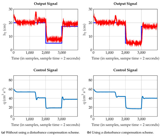
Figure 11.
Closed-loop performance of the Coupled Tanks Liquid Level Control system for several operation setpoints, for = 5.
6.2. Yeast Fermentation Reactor Temperature Control
For this evaluation scenario, the parameters of the MPC controller are presented in Table 6.

Table 6.
Parameters of the model-based predictive controller for the Yeast Fermentation Reactor Temperature control.
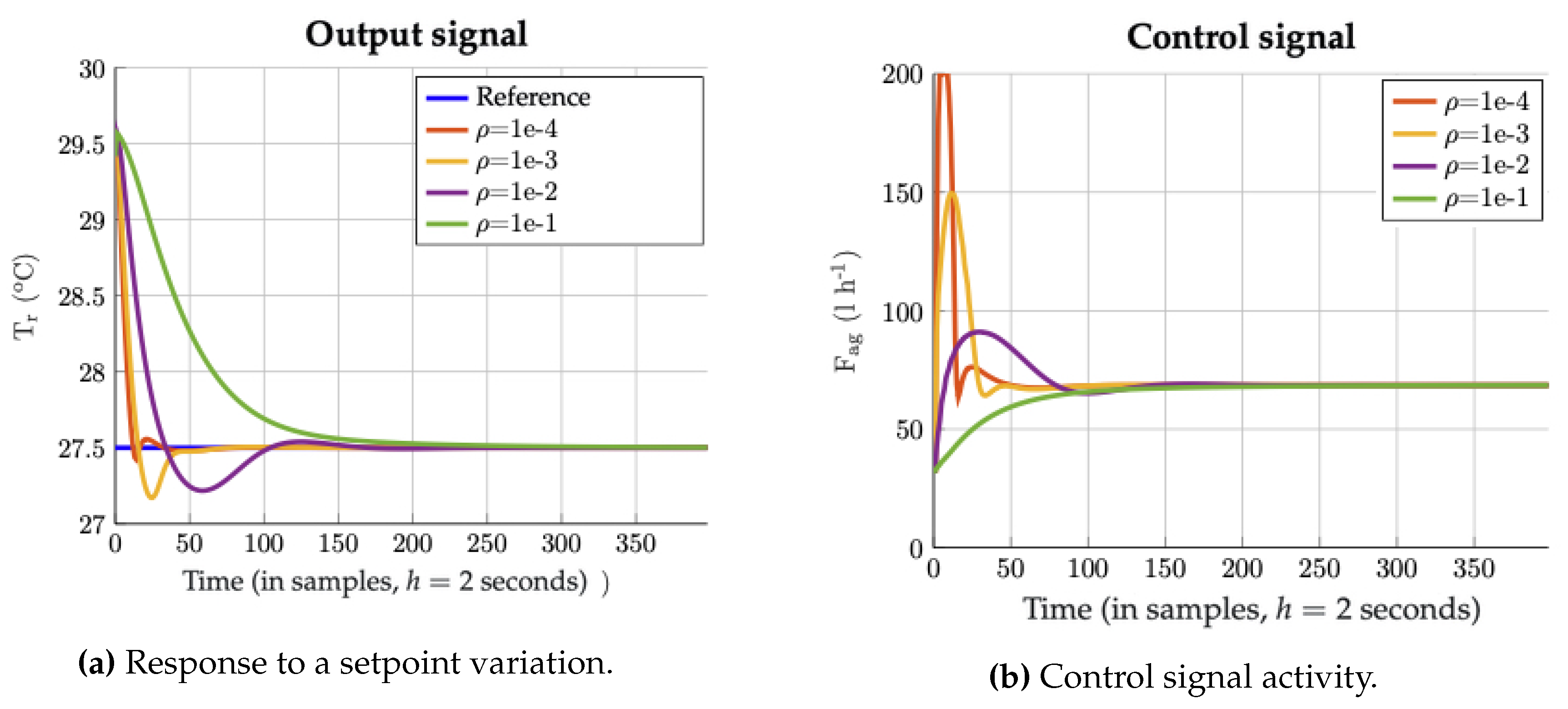
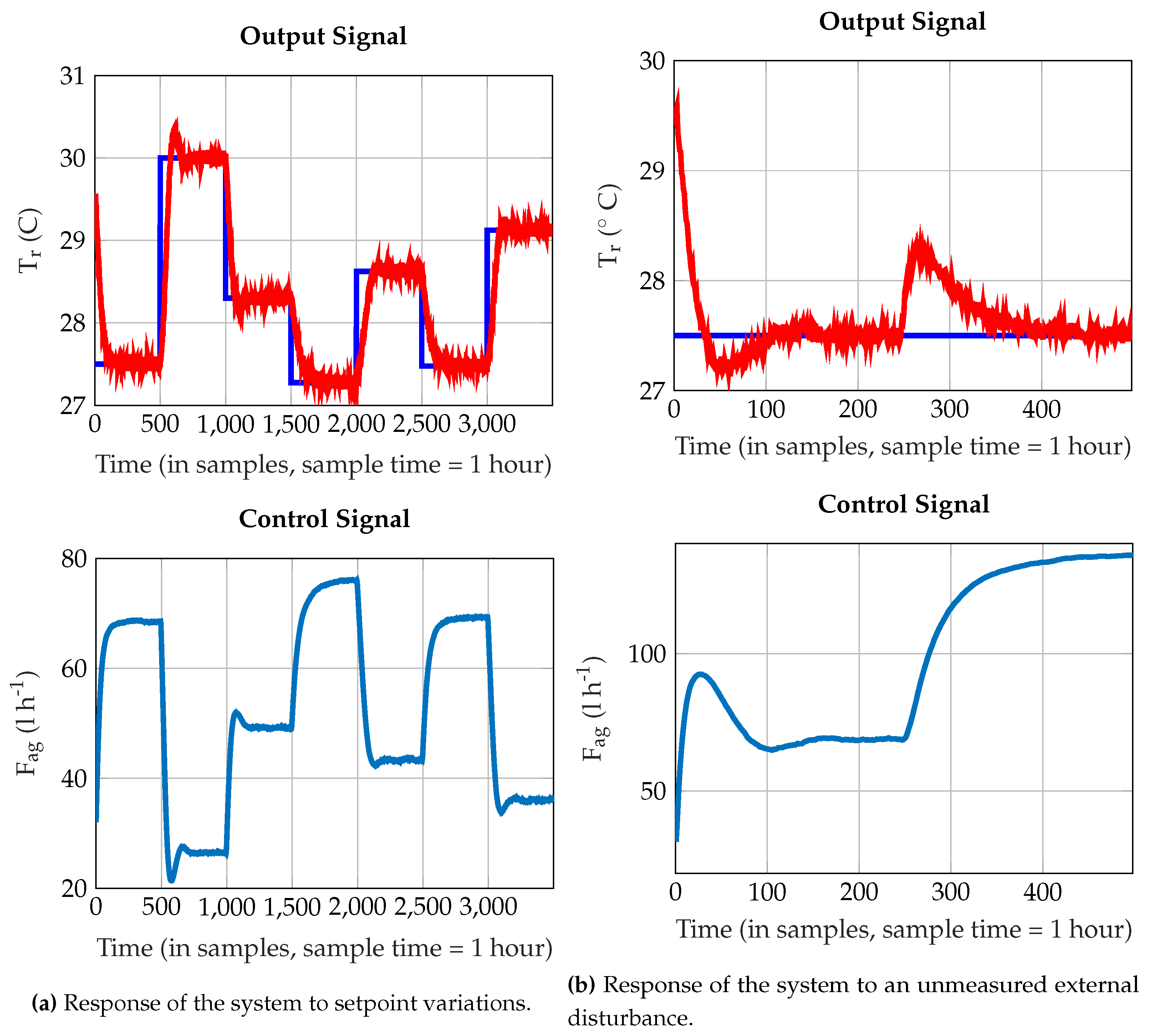
Likewise, we perform an analysis of the influence in the control signal reaction in Figure 12a,b. As depicted, higher values of correspond to a smoother control signal and output signal while lower values of correspond to a more oscillatory control signal and output signal. To conclude the controller performance analysis, it is presented in Figure 13a the performance of the temperature control system regarding setpoint variations, while in Figure 13b is presented its response after increasing the raw material’s temperature from 25 C to 27 C at sample 250. This variation acts as unmeasured external disturbance to the control system. The controlled variable measurement is also corrupted by Gaussian white noise with zero mean and variance of 0.05 C.
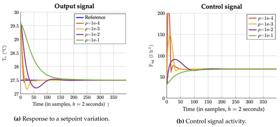
Figure 12.
Influence of the parameter (Control action attenuation factor) in the dynamic behavior of the control system.
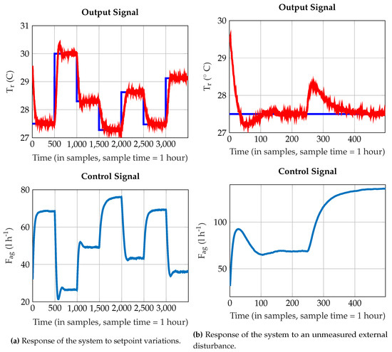
Figure 13.
Closed-loop performance of the Yeast Fermentation Reaction Temperature Control system.
7. Conclusions
In this paper was presented a technique for identification and control of non-linear systems with ANNs based on the Tensor Flow implementation. According to the results obtained in the example scenarios, this controller can follow the desired setpoint (within the operating range of the system) and to successfully overcome the influence of unmeasured external disturbances.
One advantage of this controller implementation is the ease with which it is tuned. Based on several training epochs that covered the nominal system operation conditions, one was able to develop a control loop capable of manipulating the controlled variable according to the desired reference. It is important to highlight that this result was achieved with a limited dimensionality model of the process, without even considering the influence of external disturbances. Surely higher dimensionality models could easily be obtained with a Tensor Flow structure but, a smaller Single-Input/Single-Output model approach enabled the use well know control algorithms, without entering the domains of multiple variable control problems.
However, one of the disadvantages of obtaining the controller output based on non-linear numerical optimization methods is the time it takes to calculate the control signal. For a slow dynamic system, this problem is not troublesome but, for faster systems the control signal must be calculated within the sampling period. This constraint may introduce a trade-off between model dimensionality/controller performance and the computational resources available to solve the problem.
Nevertheless, the proposed scheme stands as a generic and robust controller synthesis approach that can be applied to a multitude of application scenarios that may require an escalation on the model dimensionality, number of neurons and hidden layers.
Author Contributions
R.A. was responsible for the idea conceptualization, provided scientific supervision and was responsible for technical manuscript writing. J.A. was responsible for technical implementation. A.M. and R.E.M. provided scientific supervision. All authors have read and agreed to the published version of the manuscript.
Funding
This work was partially funded by National Funds through FCT—Foundation for Science and Technology, in the context of the projects: ID/CEC/00127/2019.
Conflicts of Interest
The authors declare no conflict of interest.
References
- Camacho, E.F.; Bordons, C. Model Predictive Control, 2nd ed.; Springer: London, UK, 2007. [Google Scholar]
- Cutler, C.R.; Ramaker, B.L. Dynamic matrix control—A computer control algorithm. In Proceedings of the Joint Automatic Control Conference, San Francisco, CA, USA, 13–15 August 1980; Volume 17, p. 72. [Google Scholar]
- Clarke, D.; Mohtadi, C.; Tuffs, P. Generalized predictive control—Part I. The basic algorithm. Automatica 1987, 23, 137–148. [Google Scholar] [CrossRef]
- Lee, J.H. Model predictive control: Review of the three decades of development. Int. J. Control Autom. Syst. 2011, 9, 415. [Google Scholar] [CrossRef]
- Sheta, A.; Braik, M.; Al-Hiary, H. Identification and Model Predictive Controller Design of the Tennessee Eastman Chemical Process Using ANN. In Proceedings of the 2009 International Conference on Artificial Intelligence, Las Vegas, NV, USA, 13–16 July 2009. [Google Scholar]
- Eaton, J.W.; Rawlings, J.B. Model-predictive control of chemical processes. Chem. Eng. Sci. 1992, 47, 705–720. [Google Scholar] [CrossRef]
- Mohanty, S. Artificial neural network based system identification and model predictive control of a flotation column. J. Process Control 2009, 19, 991–999. [Google Scholar] [CrossRef]
- Bolognani, S.; Bolognani, S.; Peretti, L.; Zigliotto, M. Design and implementation of model predictive control for electrical motor drives. IEEE Trans. Ind. Electron. 2008, 56, 1925–1936. [Google Scholar] [CrossRef]
- Stogiannos, M.; Alexandridis, A.; Sarimveis, H. Model predictive control for systems with fast dynamics using inverse neural models. ISA Trans. 2018, 72, 161–177. [Google Scholar] [CrossRef] [PubMed]
- Guillaumin, M.; Verbeek, J.; Schmid, C. Multimodal semi-supervised learning for image classification. In Proceedings of the IEEE Computer Society Conference on Computer Vision and Pattern Recognition, San Francisco, CA, USA, 13–18 June 2010. [Google Scholar]
- Deng, L.; Li, X. Machine learning paradigms for speech recognition: An overview. IEEE Trans. Audio Speech Lang. Process. 2013, 21, 1060–1089. [Google Scholar] [CrossRef]
- Collobert, R.; Weston, J. A unified architecture for natural language processing: Deep neural networks with multitask learning. In Proceedings of the 25th International Conference on Machine Learning, Helsinki, Finland, 5–9 July 2008. [Google Scholar]
- Narendra, K.S.; Parthasarathy, K. Identification and control of dynamical systems using neural networks. IEEE Trans. Neural Netw. 1990, 1, 4–27. [Google Scholar] [CrossRef] [PubMed]
- Toleubay, Y.; James, A.P. Getting Started with TensorFlow Deep Learning. In Deep Learning Classifiers with Memristive Networks. Modeling and Optimization in Science and Technologies; James, A., Ed.; Springer: Cham, Switzerland, 2020; Volume 14. [Google Scholar]
- Chollet, F. Keras. 2015. Available online: https://keras.io (accessed on 5 June 2020).
- Jia, Y.; Shelhamer, E.; Donahue, J.; Karayev, S.; Long, J.; Girshick, R.; Guadarrama, S.; Darrell, T. Caffe: Convolutional architecture for fast feature embedding. In Proceedings of the ACM International Conference on Multimedia—MM ’14, Orlando, FL, USA, 3–7 November 2014. [Google Scholar]
- Bhardwaj, S.; Curtin, R.R.; Edel, M.; Mentekidis, Y.; Sanderson, C. Ensmallen: A flexible C++ library for efficient function optimization. arXiv 2018, arXiv:1810.09361. [Google Scholar]
- Tensor Flow Lite. 2019. Available online: https://www.tensorflow.org/lite/ (accessed on 5 June 2020).
- Banbury, C.R.; Reddi, V.J.; Lam, M.; Fu, W.; Fazel, A.; Holleman, J.; Huang, X.; Hurtado, R.; Kanter, D.; Lokhmotov, A.; et al. Benchmarking TinyML Systems: Challenges and Direction. arXiv 2020, arXiv:2003.04821. [Google Scholar]
- Lai, L.; Suda, N.; Chandra, V. CMSIS-NN: Efficient Neural Network Kernels for Arm Cortex-M CPUs. arXiv 2018, arXiv:1801.06601. [Google Scholar]
- Phan, R. Neural NetPlayground A MATLAB implementation of the TensorFlow Neural Network Playground, GitHub. Retrieved 5 June 2020. Available online: https://github.com/StackOverflowMATLABchat/NeuralNetPlayground (accessed on 5 June 2020).
- Nørgaard, M.; Ravn, O.; Poulsen, N.; Hansen, L.K. Neural Networks for Modelling and Control of Dynamic Systems: A Practitioner’s Handbook; Springer: London, UK, 2000. [Google Scholar]
- Nocedal, J.; Wright, S.J. Numerical Optimization, 2nd ed.; Springer Series in Operations Research and Financial Engineering; Springer: New York, NY, USA, 2006. [Google Scholar]
- Goodfellow, I.; Bengio, Y.; Courville, A. Deep Learning; The MIT Press: Cambridge, MA, USA, 2016. [Google Scholar]
- Ławryńczuk, M. Computationally Efficient Model Predictive Control Algorithms—A Neural Network Approach, Studies in Systems, Decision and Control; Springer International Publishing: Cham, Switzerland, 2014; Volume 3. [Google Scholar]
- Ogata, K. Modern Control Engineering, 5th ed.; Prentice Hall: Upper Saddle River, NJ, USA, 2009. [Google Scholar]
- Antão, R. Type-2 Fuzzy Logic: Uncertain Systems’ Modeling and Control; Springer: Singapore, 2017. [Google Scholar]
- Wu, D.; Tan, W. A Simplified Type-2 Fuzzy Logic Controller for Real-Time Control. ISA Trans. 2006, 45, 503–516. [Google Scholar] [PubMed]
- Nagy, Z. Model Based Control of a Yeast Fermentation Bioreactor Using Optimally Designed Artificial Neural Networks. Chem. Eng. J. 2007, 127, 95–109. [Google Scholar] [CrossRef]
- Luyben, W. Chemical Reactor Design and Control; AIChE Wiley: Hoboken, NJ, USA, 2007. [Google Scholar]
- Granzow, B. L-BFGS-B. 2017. Available online: https://github.com/bgranzow/L-BFGS-B (accessed on 5 June 2020).
- Fatehi, A.; Sadjadian, H.; Khaki-Sedigh, A.; Jazayeri, A. Disturbance Rejection in Neural Network Model Predictive Control. IFAC Proc. 2008, 41, 3527–3532. [Google Scholar] [CrossRef]
© 2020 by the authors. Licensee MDPI, Basel, Switzerland. This article is an open access article distributed under the terms and conditions of the Creative Commons Attribution (CC BY) license (http://creativecommons.org/licenses/by/4.0/).

