Article

Partially Overlapping Printing with Digital Filter to Improve Quality of Volume Hologram Printer – Numerical Simulation – †

Deptartment of Computer Engineering, Nihon University, Funabashi, Chiba 274-8501, Japan
*
Author to whom correspondence should be addressed.
This paper is an extended version of our paper published in “Hua, H.; Yamaguchi, T.; Yoshikawa, H. Partially Overlapping Printing to Improve Image Quality of Volume Hologram Printer –Numerical Simulation–. In Digital Holography and Three-Dimensional Imaging 2019; OSA: Washington, DC, USA, 2019; Paper W3A.29”.
Appl. Sci. 2020, 10(11), 3963; https://doi.org/10.3390/app10113963
Submission received: 15 May 2020 / Revised: 30 May 2020 / Accepted: 3 June 2020 / Published: 7 June 2020
(This article belongs to the Special Issue Practical Computer-Generated Hologram for 3D Display)

Abstract

:
The volume hologram printer is useful for 3D display, because it is selective to the wavelength and be able to reconstruct with the natural illumination. There are many studies of a volume hologram printer been studied to output a volume hologram from a computer-generated hologram. The final volume hologram consists of tiled small holograms and the tiling manner often causes spilt lines which will have impact on image quality. With an intent to get rid of the split lines and improve the quality, fully overlapping printing was proposed recently. Each elemental hologram is overlapped both in vertical and horizontal directions by 50%. Then, the hologram is printed four times in each area and it makes the printing speed four times slower. For this case, partially overlapping printing is proposed in this paper to improve image quality with small effect in printing speed. For partial overlapping, a digital spatial filter is projected and added to every elemental hologram. Using the digital spatial filter, different partially overlapped holograms are calculated and reconstructed to compare to the non-overlapped ones. The simulation result shows that the overlapped one (10% in both vertical and horizontal) has much weaker gaps and black lines.

1. Introduction

Various kinds of hologram printers have been studied [1,2,3], and holographic stereogram printers have been studied for many years and commercialized by several companies [1,2]. The holographic stereograms are basically made from an array of 2D images and phase added stereograms [4], which include phase information to improve image quality and are used to generate a photo-realistic hologram [5]. With the development of the computer-generated holograms (CGH) of 3D objects, it becomes easier to calculate and print the plane transmission hologram [3]. For CGH printing, an electron beam printer [6] and a laser lithograph [7] provide quality printing. Since these are both high cost, some studies on low cost hologram printers have been proposed [3]. Although the plane transmission hologram is easy to print, it has a chromatic dispersion, which causes image blur with white light illumination. On the contrary, the volume reflection hologram has wavelength selectivity and causes no chromatic dispersion and it is easy to show 3D images with white light illumination. Although the transmission hologram can be optically transferred to a volume hologram manually [8], the automatic volume reflection hologram printer still has been studied [3,9,10,11,12]. The main principle of a volume hologram printer is a reconstructed image from the plane CGH which is optically transferred to a photo-sensitive material as the volume reflection hologram [3]. The volume hologram printer is also used to fabricate a holographic optical element for a laser 3D display [13]. Since the resolution of the spatial light modulator (SLM),which is used to display plane CGH, is usually of the megapixel order, the optically transferred volume hologram’s size will be in mm order. Then, all of the mm order’s transferred holograms are tiled to make a larger hologram. This tiling manner is recorded by using an X-Y motorized stage, which will cause phase discontinuity and image degradation in reconstruction by a diffraction effect at each small hologram. Therefore, if the size of a sub-hologram is too large, the split lines and cells of sub-holograms are visible, which reduce the image quality [11]. For this case, a fully overlapping approach [11,12] is proposed where the overlap ratio is 50% in both horizontal and vertical directions. Nevertheless, the printing speed is reduced by one quarter. To improve image quality with little loss in printing speed, a partially overlapping approach was proposed in the conference paper [14]. If the mm order’s transferred holograms are simply overlapped partially, there will be a strong intensity non-uniformity (higher intensity in the overlapped parts than the non-overlapped parts) that causes the split lines and reduces the quality. With this in mind, a digital filter is applied to the overlapping area to control image intensity. In the present paper, the partial overlapping is described in more detail, and the results of the numerical simulation show that the digital filter is feasible to improve the image quality.

2. Volume Hologram Printer

Since the volume hologram has 3D structure, it is not practical to calculate and print the volume hologram directly. Therefore, the plane hologram is calculated and its reconstructed image is transferred to volume hologram optically. Figure 1 shows a basic configuration of the volume hologram printer [9]. A part of the CGH is displayed on a liquid crystal on silicon (LCOS) as the SLM. The reconstructed image from the CGH is transferred to a photosensitive material with a reference beam entering from the other side to make the volume reflection hologram, as shown in Figure 2. Since the transferred hologram is very small, many holograms are tiled to form a practically sized hologram. The small transferred hologram is also called as an elemental hologram.

3. Making of the Primary Plane Hologram

The reconstructed image from the CGH is recorded in a photosensitive material (holographic plate) as the volume reflection hologram. This section describes the calculation method of the primary plane hologram as CGH and digital filtering to record a partially overlapped secondary volume hologram.

3.1. Calculation of the Primary Plane Hologram

The primary plane hologram is calculated as the lensless Fourier hologram [15] as show in Figure 2. Since the detailed calculation method is described in the previous paper [9], the main points are described here. The 3D object model is assumed as a collection of self-illuminated points [16]. The sum of complex amplitudes from object points is interfered with the complex amplitude from the point reference source placed in the origin, or side of the object. Figure 3 shows a virtual window and a reference point source for CGH calculation. The virtual window has the same size and position of the secondary volume hologram to avoid unnecessary calculation. The calculation is done only for light waves which pass the virtual window. The reconstructed image will appear at the same position of the original object when the CGH is illuminated with the conjugate wave of the reference wave. The conjugate image will also appear at the point symmetric position to the origin as shown in Figure 2 and Figure 3.

3.2. Applying Digital Spatial Filter to the Calculated Primary Plane Hologram

If the mm order’s transferred holograms are simply overlapped partially, they will have much higher image intensity in the overlapped parts than the non-overlapped parts, which will cause split lines and reduce image quality. To improve this case, the intensity non-uniformity of the overlapped part should be counterbalanced to make it continue. The reconstructed image, which is the result of the first hologram calculated as a lensless Fourier hologram [9], should reduce image intensity near its edges. For a uniform intensity, the first hologram, which has been Fourier transformed, is multiplied with a spatial digital filter as shown in Figure 4a, then inverse Fourier transformed to obtain a filtered or intensity controlled hologram. The amplitude distribution of the filter is defined as:
f ( x , y ) = f x ( x ) f y ( y ) .
Square of f x ( x ) and square of f y ( y ) are table shape function and written as:
f x ( x ) = 0 ( x < x 1 ) ( x 1 + x ) / a ( x 1 x < x 1 + a ) 1 ( x 1 + a x < x 1 a ) ( x 1 x ) / a ( x 1 a x < x 1 ) 0 ( x 1 x )
where a is an overlapping width, and x 1 and x 1 are left and right coordinates of the reconstructed image plane shown in Figure 3. The horizontal overlap ratio is defined as a / W .
f y ( y ) = f y ( | y | ) ( 0 y ) 0 ( 0 < y < y 1 ) ( y y 1 ) / b ( y 1 y y 1 + b ) 1 ( y 1 + b < y < y 2 b ) ( y 2 x ) / b ( y 2 b y y 2 ) 0 ( y > y 2 )
where b is an overlapping height, and y 1 and y 2 are bottom and top coordinates of the reconstructed image plane shown in Figure 3. The vertical overlap ratio is defined as b / H . Figure 4a is a sample of digital spatial filter image in intensity ( f 2 ( x , y ) ) whose resolution is same as the first hologram (4096 × 2160 pixel). Overlapping ratios defined below are 10% in horizontal and 10% in vertical. The white and gray parts are the window of reconstructed image plane. The black part is outside of the window with a value of zero. The middle white part is non-overlapped with a value of one. The gray part around the its edge is overlapped part with a value changes gradually from one to zero. Figure 4a shows the closeup of the top right filter area as marked with rectangle in Figure 4a. Based on Figure 4 and Equation (2), two different types of hologram tiling are shown in Figure 5a–c are normal edge in three kind joints and Figure 5d–f are filtered ones. Though in normal ones, well joint with edge as shown in Figure 5b can solve the intensity problem and have good results in simulation, the quality of printed hologram also has problems in calculation of points data. The filtered ones, which is used to improve the quality, show three kind results in gap, aligned and overlapped. Figure 5d,f are insufficient overlap and excessive overlap. Similar with normal edge, the insufficient and excessive ones will cause the intensity distribution to be uneven—lower intensity with the black gaps between elemental holograms and higher intensity with overlaps. A comparison of these cases, shown in Figure 5e, is well aligned with the filtered edge. A filtered hologram can solve the problem of image intensity caused by misalignment and reduce the influence of the calculation problem.

4. Results from Numerical Simulation

Numerical simulations are performed with parameters listed in Table 1, based on the volume hologram printer in the author’s lab. Figure 6 shows numerical reconstruction simulations of 2D model (USAF-1951 resolution chart) from normal, overlapped holograms without filter and with filter. Although the simulation has been done with perfect alignment of elemental holograms, visible dark gaps between elements are observed in the normal output shown in Figure 6a. The hologram consists of 24 elemental holograms—four in horizontal and six in vertical. Since the object is assumed as the collection of self-illuminated points, such gaps might be caused sampling errors of points between elements. Figure 6b shows reconstructed image from the overlapped hologram without the digital filter with 10% overlap in both vertical and horizontal. The hologram consists of 40 elemental holograms—five in horizontal and eight in vertical. Bright strips appear in the reconstructed image because the overlapped areas are recorded twice and it makes the overlapped areas brighter. Figure 6c shows reconstructed image from the overlapped hologram with the digital filter (10% overlap in both vertical and horizontal). One can find that the boundaries between elements are less visible than other results. Figure 7 shows numerical reconstruction simulations of a 3D model (skull) from normal, overlapped holograms without filter and with filter. The all holograms consist of 60 elemental holograms—six in horizontal and ten in vertical. Therefore, the printing time of all holograms will be the same. Figure 7a shows the result of normal output without overlapping. The split lines among each elemental holograms are obviously. With 10% in horizontal and 10% in vertical of overlapping, the images without filter and with filter are shown in Figure 7b,c, respectively. Bright grid appears in Figure 7b, of which the digital filter is not applied. In contrast, intensity fluctuations become smaller with the digital filter as shown in Figure 7c. From Figure 6c and Figure 7c, it turns out that the proposed filter is effective to improve image quality of the volume hologram printer.

5. Conclusions

To improve the image quality of volume hologram printer, partial overlapping with 10% in both vertical and horizontal directions approach multiplied with a digital spatial filter is proposed in this paper. Since the hologram printer records many holograms tiled in both horizontal and vertical directions, intensity fluctuations between elemental holograms cause problems. The filter is applied to the first hologram and it controls the intensity around the edges of the reconstructed image from the hologram. The reconstructed image from the first hologram is recorded as the volume hologram, and volume holograms are tiled with partial overlapping. The limitation of the proposed method is that the overlap ratio has a trade off between compensation and printing speed. Compared with the numerical experimental results of partial overlapping with a digital filter and normal outputs, the proposed method shows effectiveness which makes it feasible to be applied in our future work.

Author Contributions

Conceptualization, H.Y.; Data curation, H.H.; Software, H.H. and T.Y.; Supervision, T.Y. and H.Y.; Writing—Original draft, H.H.; Writing—Review & editing, H.Y. All authors have read and agreed to the published version of the manuscript.

Acknowledgments

This work was supported by Japan Society for the Promotion of Science (JSPS) KAKENHI grant number 16H02819.

Conflicts of Interest

The authors declare no conflict of interest.

Abbreviations

The following abbreviations are used in this manuscript:
CGHComputer-Generated Hologram
LCOSLiquid Crystal on Silicon
SLMSpatial Light Modulator

References

  1. Benton, S.A.; Bove, V.M., Jr. Holographic Imaging; John Wiley & Sons, Inc.: Hoboken, NJ, USA, 2008; p. 270. [Google Scholar]
  2. Saxby, G.; Zacharovas, S. Practical Holography, 4th ed.; CRC Press: Boca Raton, FL, USA, 2015. [Google Scholar]
  3. Yoshikawa, H.; Yamaguchi, T. Review of Holographic Printers for Computer-Generated Holograms. IEEE Trans. Ind. Inform. 2016, 12, 1584–1589. [Google Scholar] [CrossRef]
  4. Yamaguchi, M.; Hoshino, H.; Honda, T.; Ohyama, N. Phase-added stereogram: Calculation of hologram using computer graphics technique. Proc. SPIE 1993, 1914, 25–31. [Google Scholar] [CrossRef]
  5. Kang, H.; Stoykova, E.; Yoshikawa, H. Fast phase-added stereogram algorithm for generation of photorealistic 3D content. Appl. Opt. 2016, 55, A135. [Google Scholar] [CrossRef] [PubMed]
  6. Yasuda, T.; Kitamura, M.; Watanabe, M.; Tsumuta, M.; Yamaguchi, T.; Yoshikawa, H. Computer simulation of reconstructed image for computer-generated holograms. In Proceedings of the SPIE Opto: Integrated Optoelectronic Devices, San Jose, CA, USA, 24–29 January 2009; Bjelkhagen, H.I., Kostuk, R.K., Eds.; SPIE: Bellingham, WA, USA; Volume 7233, p. 72330H-72330H-11. [Google Scholar]
  7. Matsushima, K.; Nakahara, S. Stepping closer to the perfect 3D digital image. SPIE Newsroom 2012. [Google Scholar] [CrossRef]
  8. Kunieda, O.; Matsushima, K. High-quality full-parallax full-color three-dimensional image reconstructed by stacking large-scale computer-generated volume holograms. Appl. Opt. 2019, 58, G104. [Google Scholar] [CrossRef] [PubMed]
  9. Yamaguchi, T.; Miyamoto, O.; Yoshikawa, H. Volume hologram printer to record the wavefront of three-dimensional objects. Opt. Eng. 2012, 51, 075802. [Google Scholar] [CrossRef]
  10. Kim, Y.; Stoykova, E.; Kang, H.; Hong, S.; Park, J.; Park, J.; Hong, J. Seamless full color holographic printing method based on spatial partitioning of SLM. Opt. Express 2015, 23, 172–182. [Google Scholar] [CrossRef] [PubMed]
  11. Wakunami, K.; Oi, R.; Senoh, T.; Sasaki, H.; Ichihashi, Y.; Yamamoto, K. Wavefront printing technique with overlapping approach toward high definition holographic image reconstruction. In Proceedings of the SPIE 9867, Three-Dimensional Imaging, Visualization, and Display, Baltimore, MD, USA, 17–21 April 2016; Javidi, B., Son, J.Y., Eds.; SPIE: Bellingham, WA, USA, 2016; p. 98670J. [Google Scholar]
  12. Ichihashi, Y.; Yamamoto, K.; Wakunami, K.; Oi, R.; Okui, M.; Senoh, T. An analysis of printing conditions for wavefront overlapping printing. In Proceedings of the SPIE OPTO, San Francisco, CA, USA, 28 January–2 February 2017; Bjelkhagen, H.I., Bove, V.M., Eds.; SPIE: Bellingham, WA, USA, 2017; p. 101270L. [Google Scholar]
  13. Amano, H.; Ichihashi, Y.; Kakue, T.; Wakunami, K.; Hashimoto, H.; Miura, R.; Shimobaba, T.; Ito, T.; Miura, R.; Shimobaba, T.; et al. Reconstruction of a three-dimensional color-video of a point-cloud object using the projection-type holographic display with a holographic optical element. Opt. Express 2020, 28, 5692. [Google Scholar] [CrossRef] [PubMed]
  14. Hua, H.; Yamaguchi, T.; Yoshikawa, H. Partially Overlapping Printing to Improve Image Quality of Volume Hologram Printer –Numerical Simulation–. In Digital Holography and Three-Dimensional Imaging 2019; OSA: Washington, DC, USA, 2019; p. W3A.29. [Google Scholar]
  15. Stroke, G.W. Lensless fourier-transform method for optical holography. Appl. Phys. Lett. 1965, 6, 201. [Google Scholar] [CrossRef] [Green Version]
  16. Waters, J.P. Holographic image synthesis utilizing theoretical methods. Appl. Phys. Lett. 1966, 9, 405–407. [Google Scholar] [CrossRef]
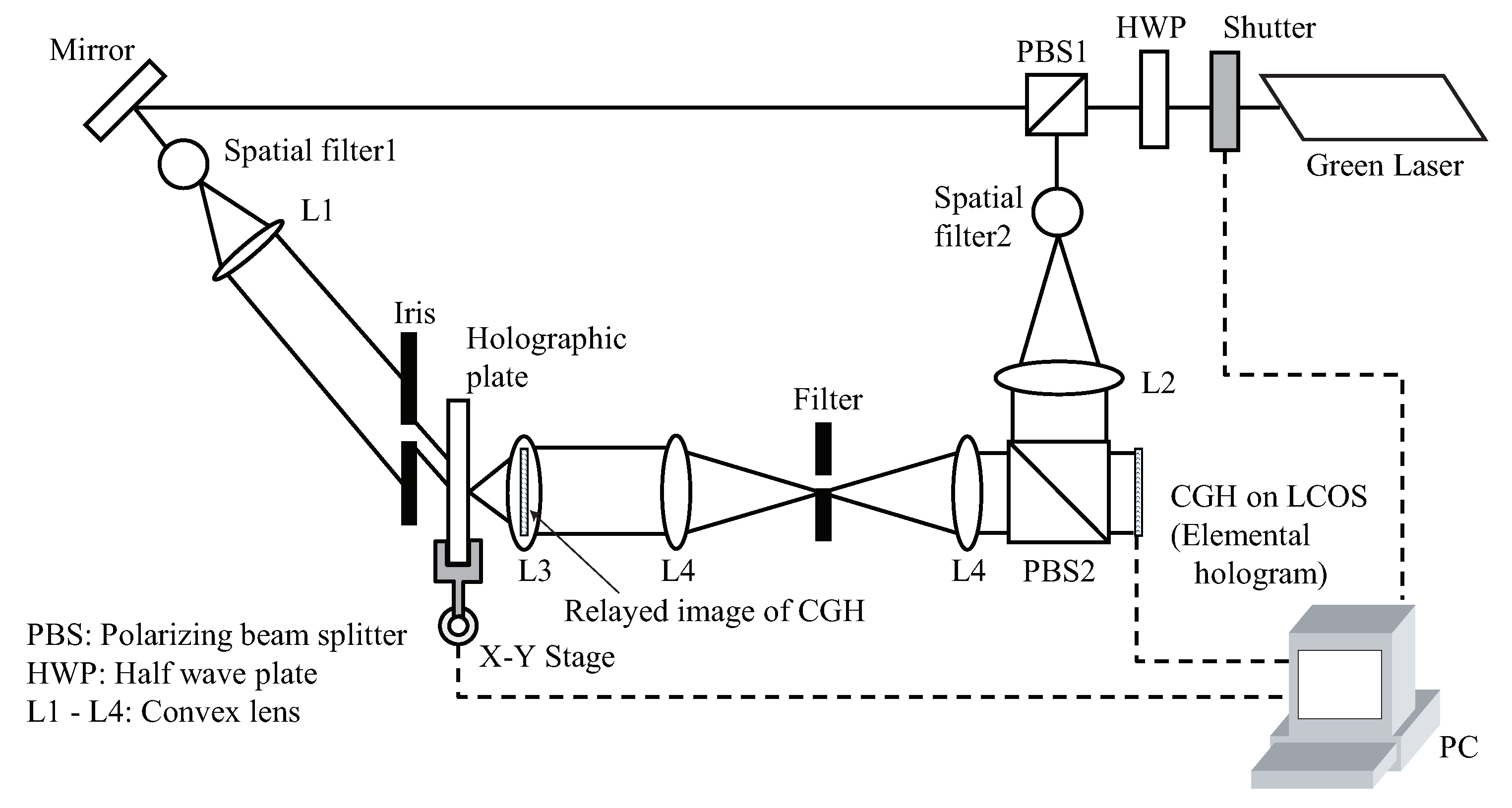
Figure 1. Basic configuration of a volume hologram printer.
Applsci 10 03963 g001
Figure 2. Configuration of computer-generated hologram (CGH) calculation and transfer.
Applsci 10 03963 g002
Figure 3. Coordinates for virtual window in the final hologram plane. The reference point source for CGH is placed at the origin.
Applsci 10 03963 g003
Figure 4. (a) Spatial filter to balance intensity on edges of the elemental volume hologram plane. (b) Closeup of the top right corner of the filter area as marked with rectangle in (a).
Applsci 10 03963 g004
Figure 5. Comparisons of normal and filtered elemental hologram tiling. Horizontal axis represents x and vertical axis represents intensity of reconstructed image. Black lines show intensity of each elemental hologram and red lines show the total intensity. (a) Gap with normal edge; (b) Aligned with normal edge; (c) Overlap with normal edge; (d) Gap with filtered edge; (e) Aligned with filtered edge; (f) Overlap with filtered edge.
Applsci 10 03963 g005
Figure 6. Reconstructed images from USAF-1951 resolution chart. (a) Normal output without overlapping; (b) 10%, 10% overlapping without filter; (c) 10%, 10% overlapping with filter.
Applsci 10 03963 g006
Figure 7. Reconstructed images from 3D skull holograms. (a) Normal output without overlapping; (b) 10%, 10% overlapping without filter; (c) 10%, 10% overlapping with filter.
Applsci 10 03963 g007
Table 1. Simulation parameters based on the volume hologram printer.
ItemValue
Laser wavelength532 nm
CGH (LCOS) pixels4096 × 2160
CGH (LCOS) pixel pitch4.0 μ m
Distance d between CGH and virtual window40 mm
(Focal length of L3)
Virtual window width W4.0 mm
Virtual window height H2.0 mm
Offset of virtual window M0.2 mm