Article

Potential Energy Recovery System for Electric Heavy Forklift Based on Double Hydraulic Motor-Generators

College of Mechanical Engineering and Automation, Huaqiao University, Xiamen 361021, China
*
Author to whom correspondence should be addressed.
Appl. Sci. 2020, 10(11), 3996; https://doi.org/10.3390/app10113996
Submission received: 20 May 2020 / Revised: 2 June 2020 / Accepted: 8 June 2020 / Published: 9 June 2020

Abstract

:
Heavy forklifts that are widely used in ports and stations have large gravitational potential energy at the lowering of the boom. As concerning the large rated power level, the engine is still the main power source for the heavy forklifts. With the increasingly stringent emissions regulations, the electric heavy forklift becomes an important choice. The structure and the working mode of an electric heavy forklift are introduced. Additionally the schematic of double hydraulic motor-generators is adopted to regenerate the potential energy when the boom is descending. The judge rule of the working mode and control strategy are analyzed. A test rig of a prototype electric heavy forklift is established. Control mode discrimination of potential energy regeneration, the control performance and the influence factors on regeneration efficiency are tested based on the test rig. The experimental results show that the discrimination method of the working mode of the proposed double hydraulic motor-generators with a potential energy regeneration system for potential energy is feasible. The descending of the lifting cylinder is consistent with the handle. The forklift can obtain the good following ability. Although the lifting cylinder descends at low velocity, the velocity is stable and the fluctuation of the rodless chamber pressure is within 0.1 MPa. With the increase of the load mass and descending velocity, the regeneration efficiency increases accordingly. The maximum efficiency is up to 74%. Hence, the proposed potential energy regeneration system is feasible and potential energy regeneration system does not affect the control performance of the boom.

Graphical Abstract

1. Introduction

Non-road mobile construction machinery powered by a traditional internal combustion engine has problems such as low efficiency, bad emission and high pollution, which have a great impact on source utilization and global climate. Due to low noise, zero emission, pollution-free characteristics, pure electric drive construction machinery becomes a new development direction of construction machinery [1,2,3,4,5,6,7,8]. Electrification of the forklift is developed early and is relatively mature in the field of construction machinery. However, currently, the pure electric forklift on the market uses the low voltage system basically and the rated load is under 5-ton, which are called small type forklifts. There is a lot of gravitational potential energy that can be recovered for all the forklifts. Their lifting system frequently reciprocates up and down and converts the potential energy into heat energy, causing the high temperature of the hydraulic system and the short life of hydraulic components [9]. In view of the above problems, a potential energy regeneration system (PERS) can be put forward to regenerate the potential energy.
Qian et al. tested a forklift with a load of 1 ton. The test results showed that the lifting system consumed 3361 kJ, the walking system consumed 4110 kJ and the steering system consumed 907 kJ, that counted for 40.1%, 49.1% and 10.8% of the total energy consumption, respectively [10,11]. Wang et al. did similar research and used the similar test principle. However, they also considered the energy consumption of the tilting cylinder. The test results showed that the lifting, walking, steering and tilting accounted for 41%, 44%, 12% and 3% of the total energy consumption, respectively [12]. It can be seen that the lifting system consumes most of the energy.
Minav et al. did a lot of researches on the PERS for the electric forklift. In the year 2009, the feasibility of load potential energy regenerated was predicted, and the influence of different loads and different descending velocity on potential energy regeneration was analyzed [13]. In the year 2011, the efficiency of the electric motor (EM), hydraulic pump and valves were analyzed [14]. In the year 2013, the potential energy regeneration scheme of direct servo motor control technology was proposed. The energy saving efficiency of the system was measured, and the advantages of the electric pump drive system were verified [15]. The same year, the PERS of the electric forklift with a lithium battery was built, and the regeneration efficiency of the system at a different velocity was analyzed [16]. Andersen et al. proposed a forklift with the power system of a battery-EM-hydraulic pump. The test results showed that the energy regeneration efficiency could be up to 40% [17,18]. The efficiency of PERS was increased by 18% in the low speed mode and 30% in the high speed mode. Jiang et al. controlled the valve group to drive the hydraulic motor to make EM generate electric energy when the boom is descending, and stored the recovered energy into the battery of the forklift. The regeneration efficiency was up to 20% [19]. These research verified that the potential energy could be regenerated and the regeneration efficiency was high.
Although the PERS is successfully applied to small type forklifts, there are a few PERSs developed for electric heavy forklifts (EHFs). A study on PERS of EHFs is relatively less. For an EHF whose rated load is more than 12 tons, there are some differences to the small type forklift. In this article, a double hydraulic motor-generators (HMGs) with PERS to regenerate the potential energy when the boom descending is proposed. The structure schematic and the working mode are introduced. The control strategy is analyzed according to the working mode. Then, the proposed schematic is tested through a 25-tons prototype EHF.

2. Energy Regeneration Methods for EHFs

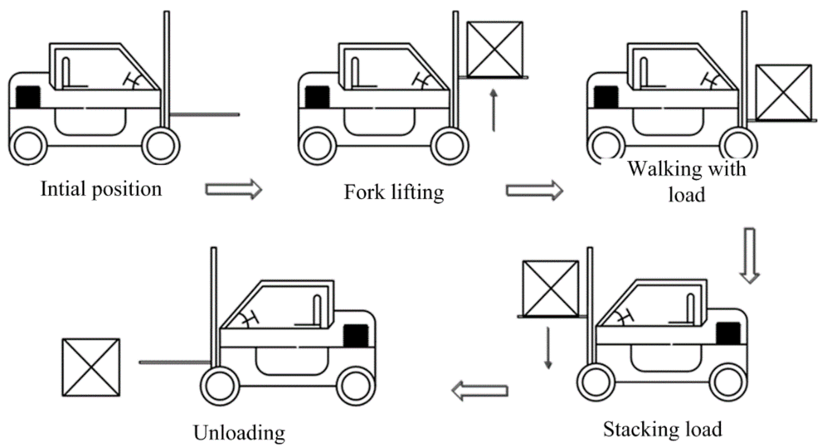
2.1. Structure of the EHF

An EHF had been developed in our prior research. The structure of the EHF is shown in Figure 1, it can be seen that the low efficient torque converter is eliminated. Hydraulic systems and the walking system are driven by separate EMs. The common characteristics about the EHF can be summarized as below: due to the large mass associated with the boom, when actuators go down, the gravitational potential energy and inertial energy that are dissipated into heat in the control valves are not easy to be regenerated in conventional heavy forklift. However, for an EHF with batteries in the power system, there is a possibility to utilize the gravitational potential energy. It can use a battery to store the potential energy when the boom goes down. For example, employing a hydraulic motor and a generator connected to the meter-out port of the control valve is one solution to this problem. So, the gravitational potential energy can be utilized and converted into electric energy in an EHF. In Figure 1, EMC is short for an electric motor controller. Additionally, BMS is short for battery management system.

2.2. Working Mode

An operation roadmap of a forklift is shown in Figure 2. The purpose of the forklift is to carry the cargo from A to B safely and smoothly through the standard operation and to stack them neatly in a certain order. A complete operational cycle consists of the following steps.
Firstly, forklift lifts without a load for a short distance from the initial position C and then runs along the No. 1 route to the goods. It adjusts the lifting cylinder to make the height of the forks close to that of the cargo gap and then slowly runs to the place that is just under the cargo. Forks lift the cargo off the ground and make the cargo land over the forks safely and effectively.
Secondly, forklift carries the cargo along No.2 route and slowly reverses to the open space. Additionally, then the forklift moves to position B along No.3 route and slowly lowers the forks. When the goods are safely placed at position B, the forks drop to a safe position and the forklift moves back to position D along No.4 route.
Thirdly, forklift moves along No.5 route to position C.
This is the complete operation cycle of the forklift. The distance L in Figure 2 is based on the actual situation. During the transport process, the forks must keep a certain angle and a certain distance from the ground.
A typical work cycle of a forklift is shown in Figure 3, which mainly includes the following five parts: running from the initial position to the cargo position, lifting forks with cargo, moving and transporting, stacking the cargo and unloading. In this working cycle, there are eight main working conditions, including walking, steering, lifting without a load, lowering without a load, up-tilting of forks, down-tilting of forks, lifting with a load and lowering load. Among them, there is more recoverable potential energy in the lowering load condition. This is the main point of the following discussion. Commonly, the time for lowering of the boom about 10–30 s depending on the control strategy.

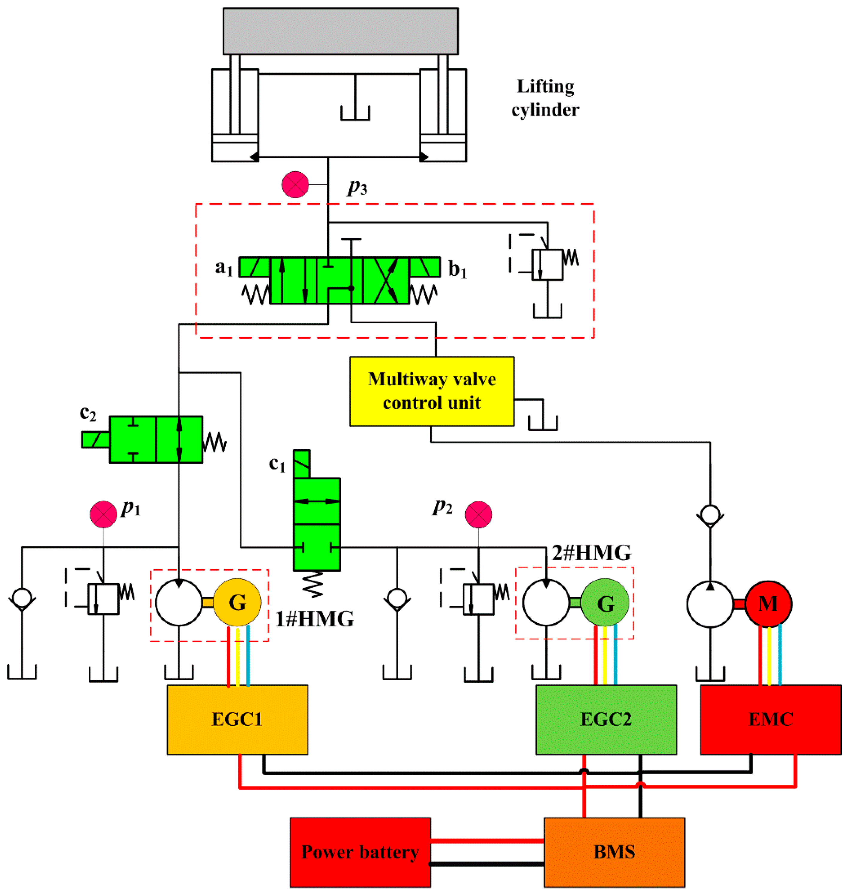
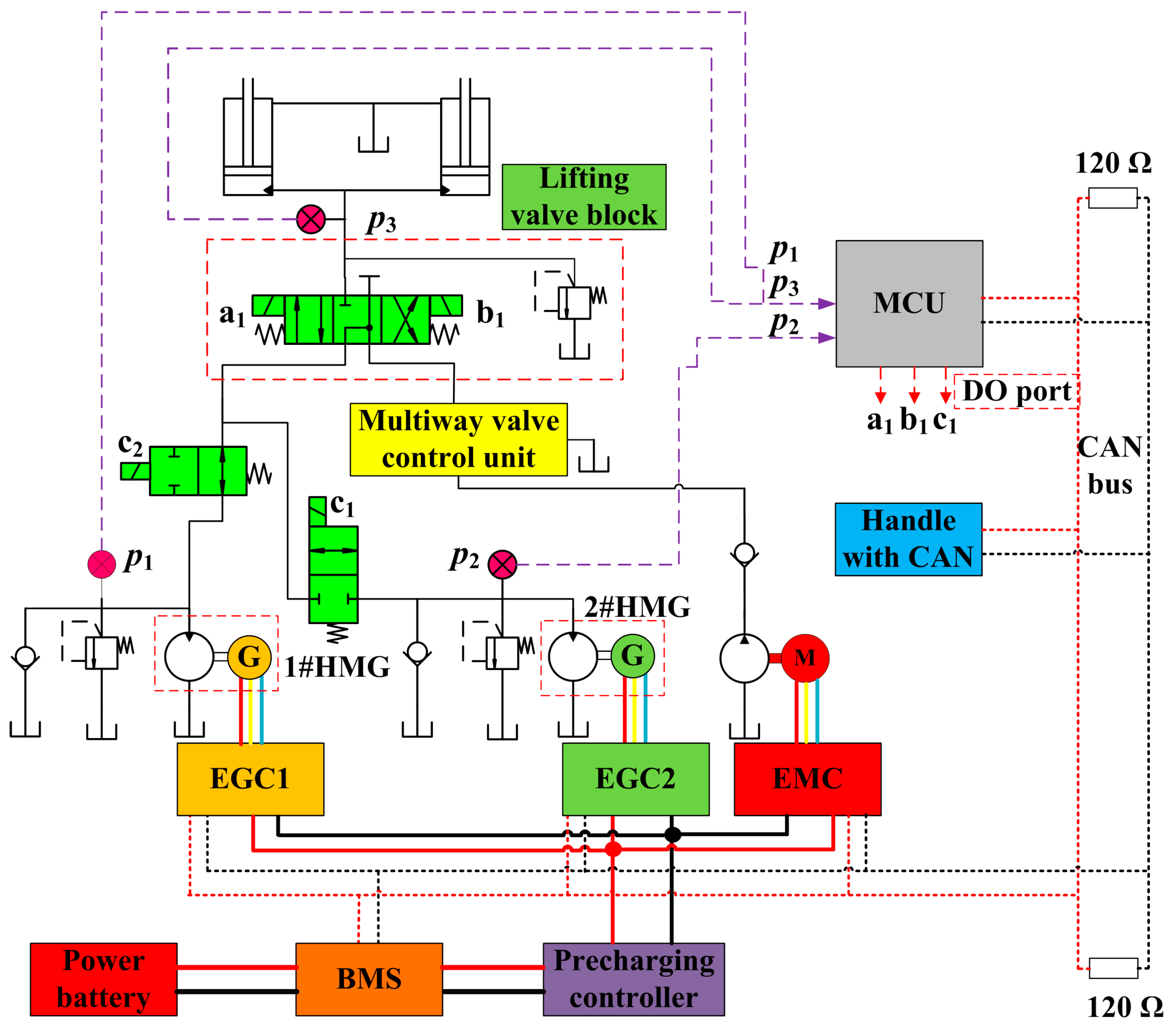
2.3. Configurations of PERS

A 25 tons heavy forklift was carried out for the PERS research in this article. The mass of the fork rack was about 5 tons and the maximum load weight was 25 tons. That is to say, the load of the full load condition was 6 times of the no-load condition. Hence, driven by a single motor, the power level of the hydraulic motor-generator (HMG) was not only relatively high, but also difficult to ensure the HMG always work in an efficient range with different loads. Two HMGs were applied in the PERS to solve this problem. The schematic of the proposed system is shown in Figure 4. Two HMGs connected to the meter-out port of the hydraulic control valve were employed to convert the gravitational potential energy of the boom into electric energy, which could be used for the later pure electric drive system. The boom down mode has the traditional throttling-controlled mode and volume-controlled mode with PERS. The throttling-controlled mode uses the conventional multiway valve to realize the throttling control to adjust the boom velocity. In HMG controlled mode, the machine control unit (MCU) controls the two sets of HMGs to realize the lowering velocity control of the boom according to the handle signal, hydraulic signal and the state of batteries and the EMs according to the control strategy. In Figure 4, EGC is short for the electric generator controller.

3. Control Strategy

The flow chart of the lifting system based on double HMG PERS is shown in Figure 5. According to the handle signal Yp, rodless chamber pressure p3 of the lifting cylinder and the state of charge (SOC) of the battery, MCU determines the control mode of lifting cylinder descending. The judgment rule of working mode and the control strategies of different work modes were as follows. In Figure 5, Yp, Ymin and Ymax are the opening, minimum opening and maximum opening of the handle, respectively. Ys is the handle opening when the mode is switched from single HMG mode to double HMG mode. p3 is the rodless chamber pressure of the lifting cylinder. Cminp is the minimum pressure of the rodless chamber allowing descending with PERS. Smax is the upper limit value of battery SOC allowing descending with PERS. n1 and n2 are the speed request value of 1# HMG and 2# HMG, respectively. a1, b1 and c1 are the electromagnets shown in Figure 4.

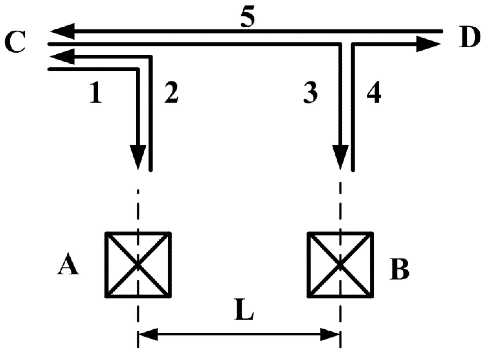
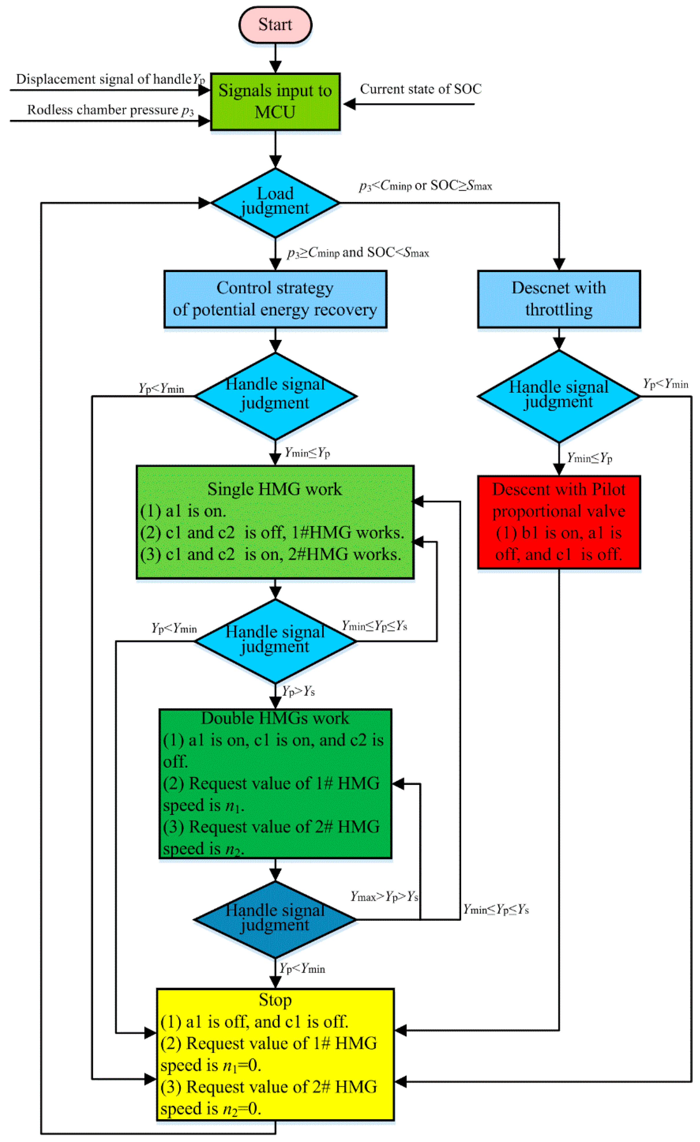
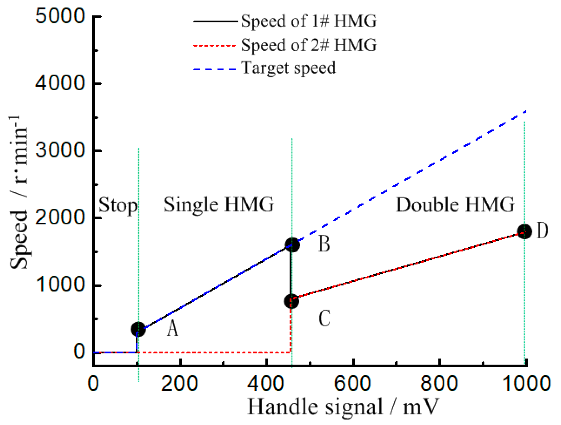
3.1. Judge Rule of the Working Mode of the Boom

The forklift is a speed-controlled system, and the handle opening represents the target velocity of the boom. When the boom descends, there is a certain energy loss of the energy regeneration unit composed of HMG and lithium battery. When the energy recovered by the external load is less than the loss generated by PERS itself, using the HMG controlled mode to control the descending velocity of the lifting cylinder will generate additional energy loss, which will reduce the energy regeneration efficiency of the whole machine. Therefore, there is a minimum load requirement for the external load under HMG controlled mode to recover the potential energy. The load is measured by detecting the rodless chamber pressure of the lifting cylinder. To prevent being overcharged by the lithium batteries, there is a requirement for the maximum allowable charging of SOC. Accordingly, the main factors influencing the decision of the control mode of lifting cylinder descending are the handle opening, the minimum rodless chamber pressure and the maximum SOC of the battery. Therefore, the judge rules for the descending mode of the lifting cylinder can be shown in Table 1.
(1)
When the rodless chamber pressure satisfies p3Cminp, and the residual charge of lithium battery satisfies SOC < Smax and the opening of the handle with controller area network (CAN) communication satisfies YminYpYs, the boom down system enters the single HMG mode.
(2)
When the rodless chamber pressure satisfies p3Cminp, and the residual charge of lithium battery satisfies SOC < Smax and the opening of the handle with CAN communication satisfies Ys < YpYmax, the boom down system enters the double HMG mode.
(3)
When the rodless chamber pressure satisfies p3 < Cminp or the residual charge of the lithium battery satisfies SOC ≥ Smax and the opening of the handle with CAN communication satisfies YminYpYmax, the boom down system enters in the traditional throttling-controlled mode.

3.2. Control Strategy

In the PERS, there is a certain proportional relationship between the control signal of the hydraulic motor and the descending velocity of the lifting cylinder. Therefore, the generator is controlled by the speed mode to improve the control performance when the lifting cylinder descends.
The potential energy regeneration control strategy consists of stop, single HMG and double HMGs, respectively, shown in Figure 6. Point A is the minimum signal of handle corresponding to the switch from the stop mode to the single HMG mode and the minimum recovery speed of 1#HMG. Point B is the handle signal corresponding to the switch from the single HMG mode to the double HMG mode and the speed of 1#HMG. Point C is the handle signal corresponding to the switch from the single HMG mode to the double HMG mode and the minimum recovery speed of 2 #HMG. Point D is the handle signal corresponding to the double HMG mode and the maximum recovery speed of 1#HMG and 2 #HMG.
Suppose the coordinates of the four points of A, B, C and D are A = (YpA, nmin), B = (YpB, nmax), C = (YpC, 0.5nmax) and D = (YpD, nmax), respectively. Where, YpA, YpB, YpC and YpD are the handle signals of points of A, B, C and D, respectively. nmin is the minimum speed when using HMG unit for single HMG mode. nmax is the maximum efficient speed of 1#HMG or 2 #HMG for the double HMGs mode.
To ensure the linear relationship between the descending velocity of the lifting cylinder and the handle signal and no abrupt changing of the boom velocity, the increment of the sum of the target speed is positively correlated with the increment of the handle signal no matter whether it is in the single HMG mode or in the double HMGs mode. That is to say, the curves are proportional.
k t = k 1 + k 2
where, kt is the proportional relationship between the total target speed and the handle signal. k1 is the proportional relationship between the target speed controlled by 1#HMG and the handle signal. k2 is the proportional relationship between the target speed controlled by 2#HMG and the handle signal.
In the stage of “Stop”, namely, Yp ∈ (0,YpA), both 1#HMG and 2#HMG do not work, namely
n 1 = n 2 = 0
In the stage of “single HMG”, namely, Yp ∈ (YpA, YpB), the relationship between speed of 1#HMG and 2#HMG and the handle signal can be given by Equation (3) or Equation (4) according to the temperature of generators. Additionally, 1#HMG takes precedence over 2#HMG. Hence, if the temperature of the generator 1 is below the maximum allowable operating temperature, 1#HMG works and 2#HMG does not work. Otherwise, 2#HMG works and 1#HMG does not work.
{ n 1 = k AB ( Y p Y pA ) + n min n 2 = 0
{ n 1 = 0 n 2 = k AB ( Y p Y pA ) + n min
where, kAB is the line slope from point A to point B. nmin is the minimum working speed of 1#HMG and 2#HMG. nmin can be deduced by the efficiency map of the hydraulic motor and generator.
In the stage of “double HMGs”, namely, Yp ∈ (YpB, Ymax), 1#HMG and 2#HMG are exactly the same. Hence, the speed of the 1#HMG and 2#HMG is the same. Additionally, the relationship between the speed of 1#HMG and 2#HMG and the handle signal can be calculated as:
n 1 = n 2 = k CD ( Y p Y pC ) + 0.5 n max
where, kCD is the line slope from point C to point D. nmax is the maximum high efficient speed of 1#HMG and 2#HMG. nmax can also be deduced by the efficiency map of the hydraulic motor and generator.
The coefficient satisfies the following formula as follows:
k t = k AB = 2 k CD

4. Experiment and Results Analysis
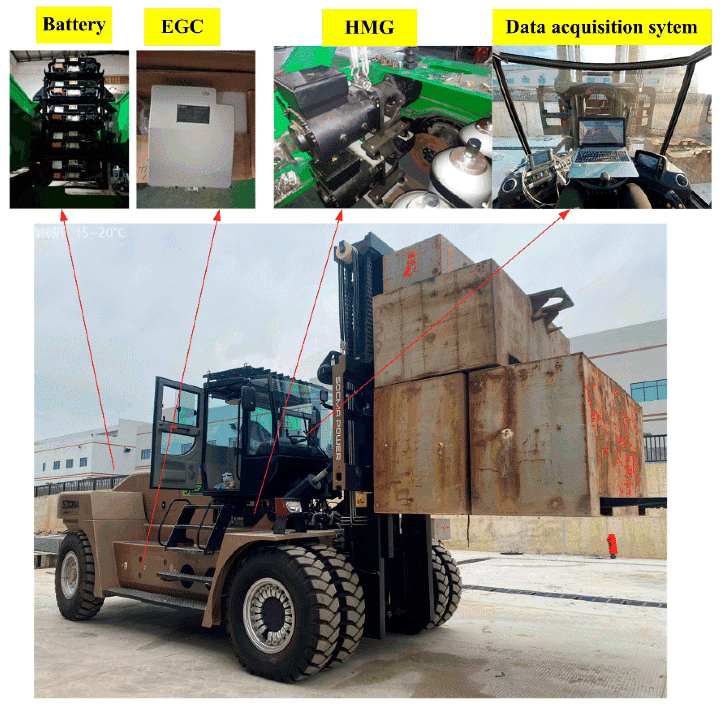
4.1. Test Rig

Experiments to test the proposed PERS on a 25-ton EHF using two separate HMG units were carried out, as shown in Figure 7. The system consisted of the power battery, two identical HMGs and their controllers EGC, one electric motor-pump and its controller EMC, a MCU, a CAN bus handle, hydraulic control units and other components, shown in Figure 8. The communication and data acquisition during the test were realized through the CAN bus, the baud rate of which was 250 K. The detailed parameters of the key component are shown in Table 2. The hydraulic motor was driven by the generator in coaxial, the speed ranges of which was from 0 to 3000 r/min and could be controlled by a frequency convertor, which is called EMC in Figure 7. The working mode and control performance of the boom were tested to analyze and compare the features of the systems. Additionally, the energy generation efficiency characteristics were compared.

4.2. Working Mode

Figure 9 shows the curve of the handle signal and the actual speeds of 1#HMG and 2#HMG during the boom descending. The whole test time was 52 s. The signal of the MCU increased firstly and then decreased according to the handle signal. According to the proposed double HMGs with PERS, the HMG works in five stages: stop, single HMG, double HMGs, single HMG and stop.
Seen from Figure 9, at time 2.9 s, the handle signal started to increase from 0 mV, and the system was in the stage of “Stop”. At time 3.3 s, the handle signal was increased to 100 mV, and 1#HMG started to work. The system entered the stage of “single HMG”. When the handle signal increased to 455 mV at time 6.65 s, the speed of the 1#HMG approached −1600 r/min. Then, the system entered the stage of “double HMGs”, and the 2#HMG started to work. Request values of the two HMGs are the same and the two curves were almost identical, which could be seen from Figure 9. When the handle slowly backed from the maximum opening to the median position, the handle signal decreased and the target speed gradually reduced accordingly. At time 16.5 s, the handle signal decreased to 455 mV and 2#HMG stopped working. Speed of 2#HMG decreased to zero with inertia and the speed of 1#HMG increased to the target speed. Then, the system entered the stage of “single HMG” again. At time 48.7 s, the handle signal was less than 100 mV and the system entered the stage of “Stop”. Speed of 1#HMG decreased to zero with inertia and the lifting cylinder was no longer descending.
Based on the above test, the discrimination method of the working mode of the proposed double HMGs with PERS for potential energy was feasible. The whole process included the stop mode, single HMG and double HMGs. Additionally, each mode could realize a response to the handle signal with the control strategy.

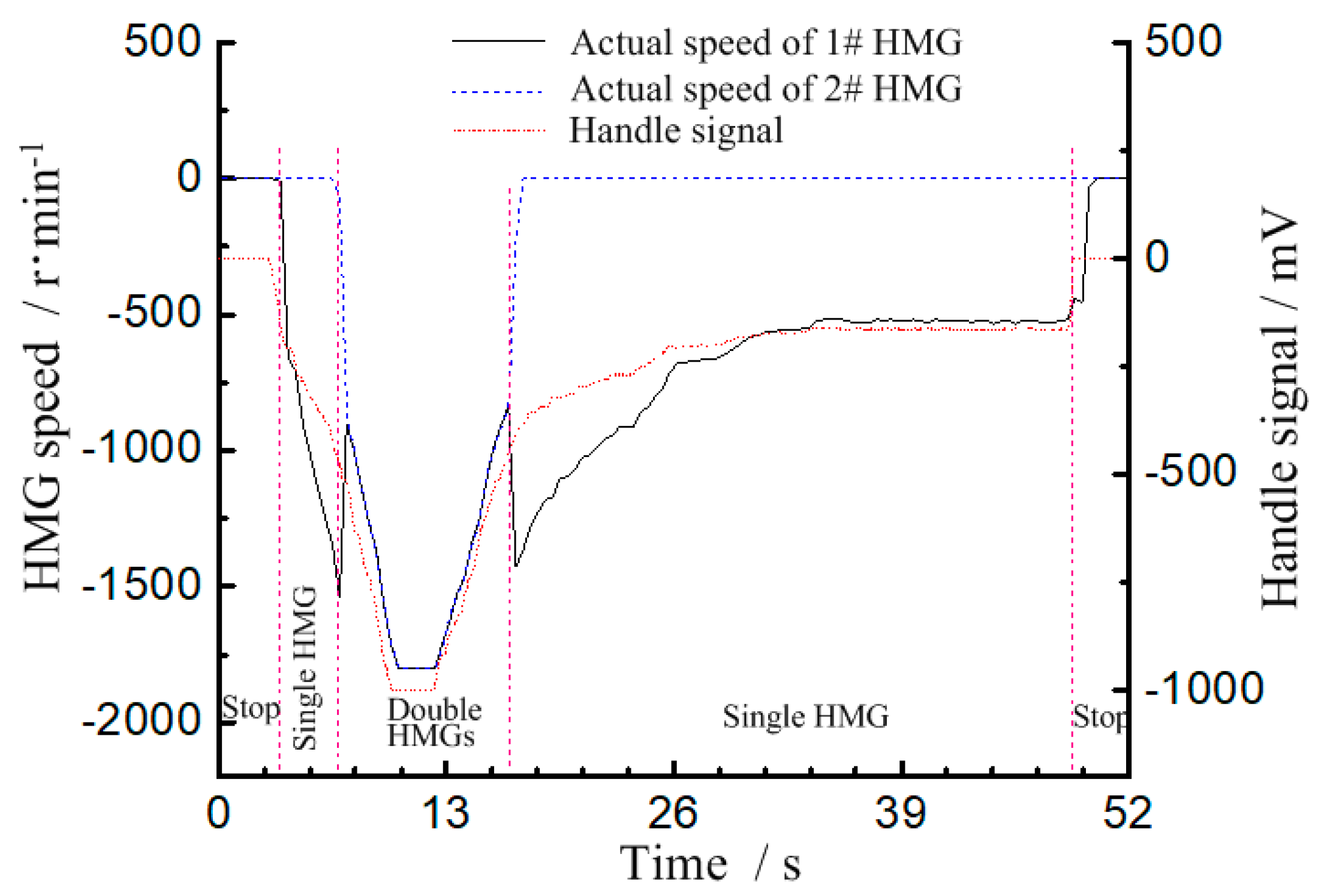
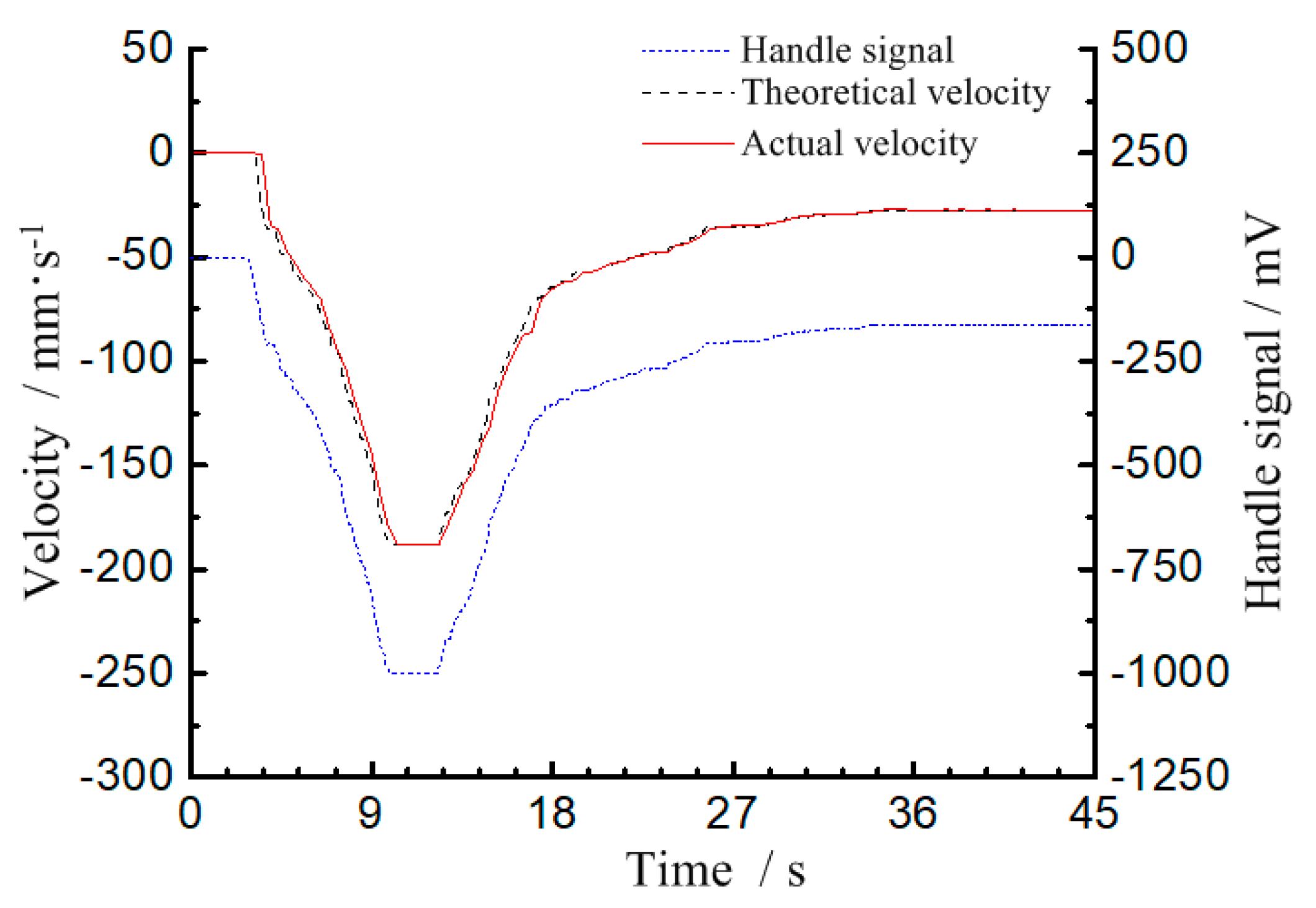
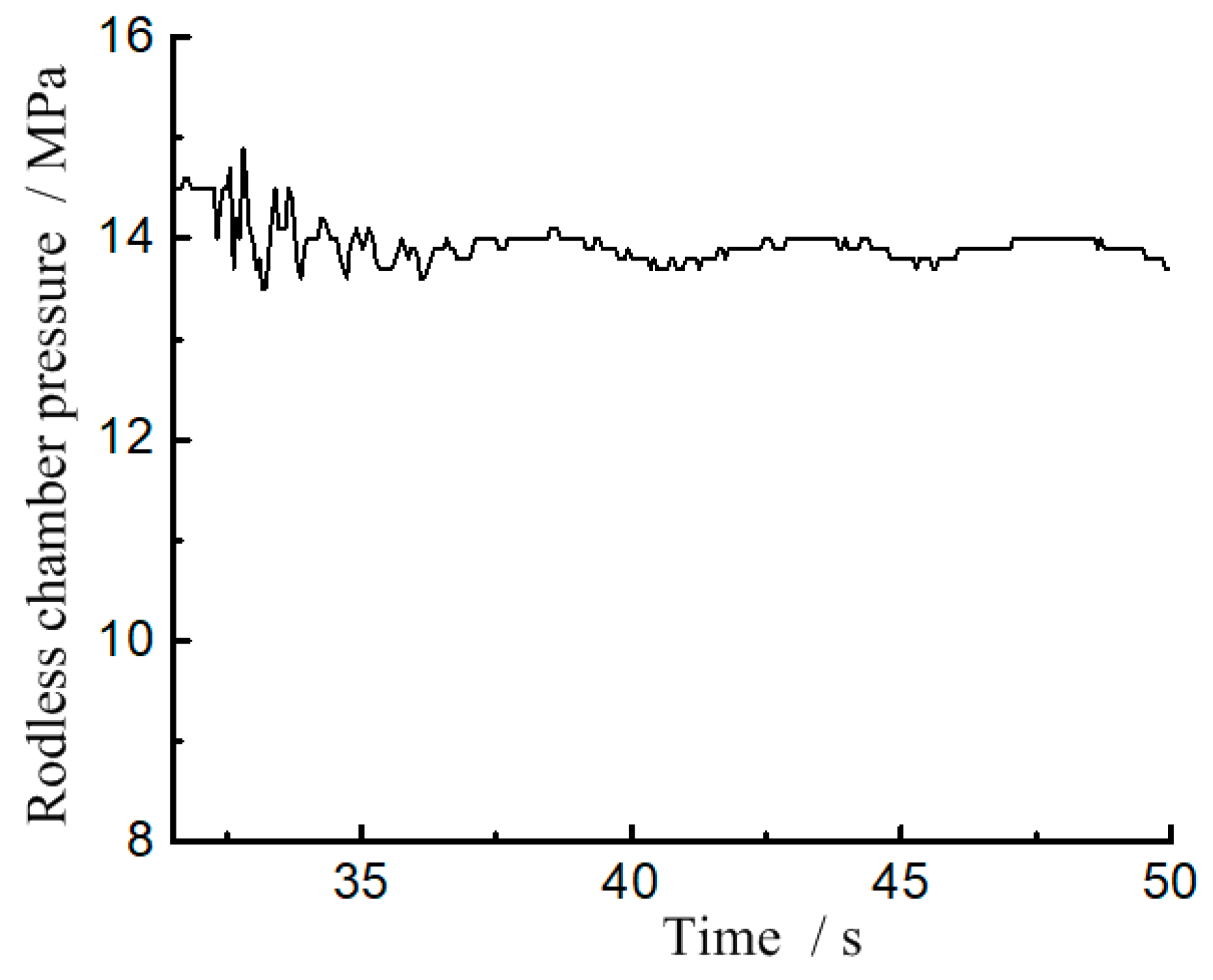
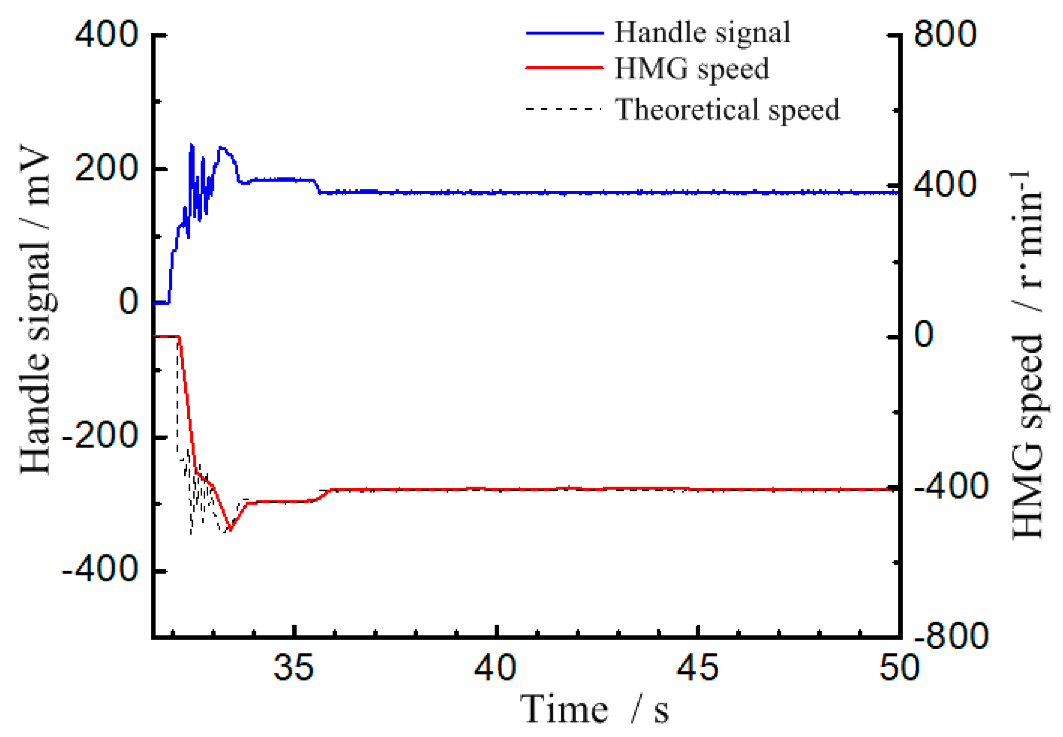
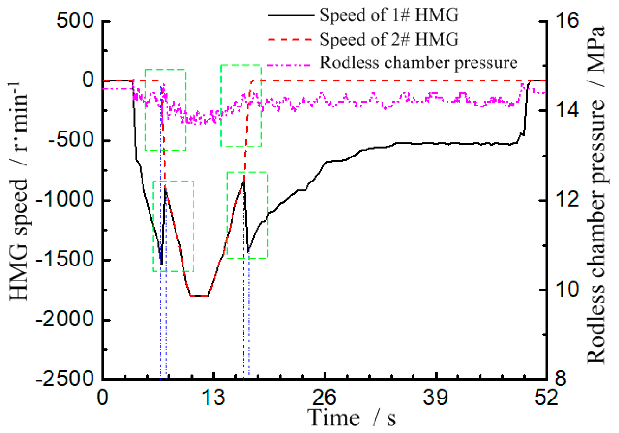
4.3. Control Performance

As concerning about that EHF is a large inertial system, the request for a dynamic response of speed is not high. The focuses are mainly on the speed following ability, speed stability during mode switching and the smoothness at low speed.
(1) Following ability
The relationship between the forklifts descending velocity and the handle signal is given in Figure 10. The handle signal gradually increased from the minimum opening degree to the maximum opening degree and then back to the minimum opening degree. Additionally, it was proven that the actual descending velocity of the forklifts was very close to the theoretical descending velocity and was consistent with the trend of the handle signal. The deviation of the descending velocity was small and the following ability was good.
(2) Stability of low descending velocity
The stability of the descending velocity is an important performance indicator for the forklifts, especially for EHFs. The minimum operating speed of the HMG was 300 r/min, but the handle signal was at the turning point between the “Stop” stage and “Single HMG” stage. Then 400 r/min was taken as the low speed performance test speed. Seen from Figure 11, the rodless chamber pressure had a small fluctuation when switching from the “Stop” stage to the “Single HMG” stage. On the one hand, it was caused by the fluctuation of the solenoid directional valve. On the other hand, it was caused by the higher target speed due to the larger initial handle signal. When HMG speed stabilized around 400 r/min, the rodless chamber pressure was around 13.9 MPa, the fluctuation was within 0.1 MPa. The overall pressure fluctuation was small. Seen from Figure 12, the actual HMG speed was very close to the target speed 400 r/min, and the stability of the speed control was good.
(3) Working mode switching characteristics
Research on working mode switching characteristics focuses on the speed following and pressure fluctuation of the two switching points. At time 6.65 s, the system switches from the “single HMG” stage to “double HMGs” stage. As shown in Figure 13 and Figure 14, though the rodless chamber pressure fluctuated about 0.5 MPa, the fluctuation range was small. Seen from Figure 15 and Figure 16, the actual speed of 1#HMG and 2#HMG were slightly different from their target speed, but the fluctuation range was also small.
At time 16.5 s, the system switched from the “double HMGs” stage to “single HMG” stage, and the pressure fluctuation range was also small. The actual speed of 1#HMG slightly fluctuated but the fluctuation range was small. Additionally, 2#HMG entered the “Stop” stage and had no effect on the descending process of the forklifts. Both the speed and pressure fluctuations were small and had little influence on the control performance of the EHF.

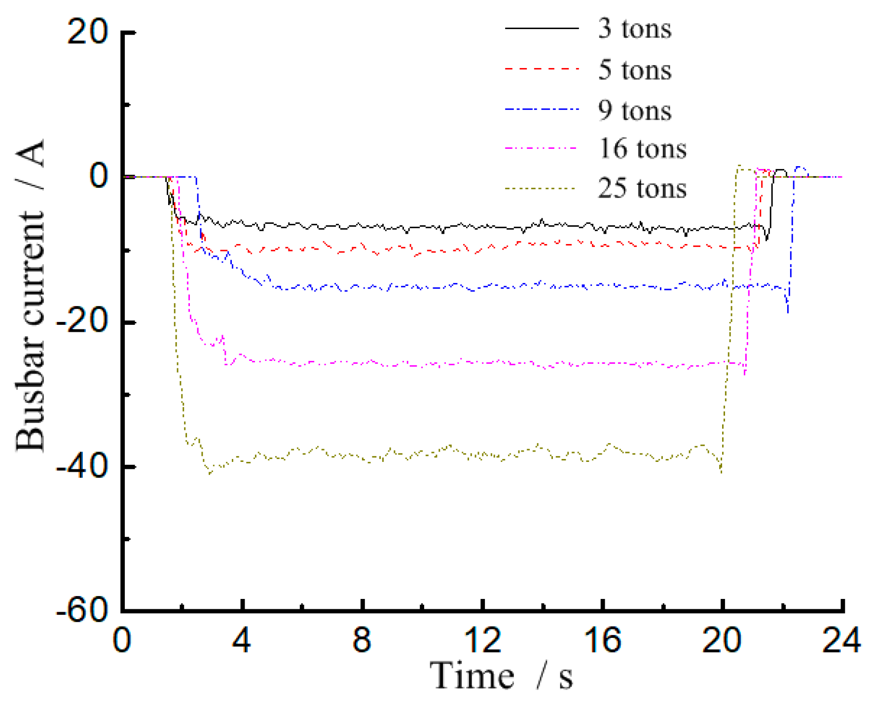
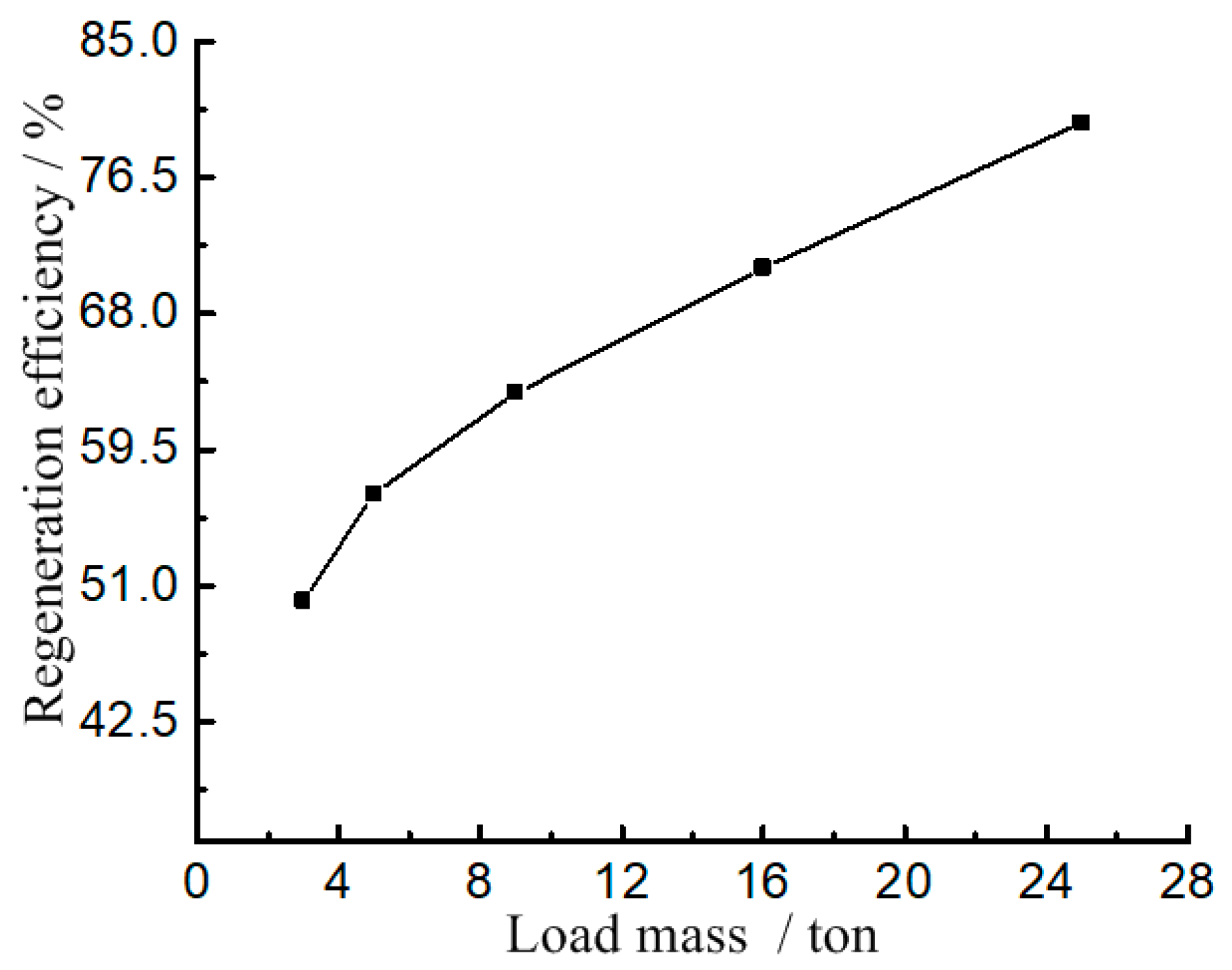
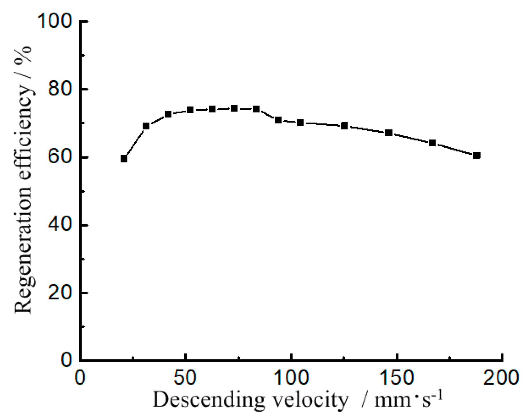
4.4. Potential Energy Regeneration Efficiency

The potential energy recovery efficiency is defined as the percentage of the charged electric quantity of the battery and the potential energy of the load and door rack in one descending process, seen in Equation (7).
η s = E Q E dL × 100 %
where, ηs is the regeneration efficiency of the potential energy of the system. EQ is the regenerated electric quantity of the lithium battery, J. EdL is the potential energy released by the descending of the door rack system and the load, J.
The charged electric quantity of the lithium battery can be described as:
E Q = 0 t U b I b d t
where, Ub is the busbar voltage of the lithium battery, V. Ib is the busbar current of the lithium battery, A. If Ib is negative, it is generating. The generated electric energy by the motor when boom descending with a load can be calculated by Equation (9).
E dL = M e g h
M e = M + M f + M fr + 1 2 M dr
where, Me is the effective mass of the load, forks, fork rack and inner door rack, kg. M is the load mass, kg. Mf is the forks mass, kg. Mfr is the mass of the fork rack, kg. Mdr is the mass of the inner door rack, kg. h is the effective descending height, m. g is the gravitational acceleration, m/s2.
Seen from Equation (9), the regeneration efficiency of the potential energy is related to the load mass and the effective descending height. The effects of load mass, effective decreasing height and descending velocity on the regeneration efficiency of the potential energy were analyzed when the lifting cylinder descended.
(1) Potential energy regeneration efficiency corresponding to a different load mass
To study the influence of different load mass on the potential energy regeneration efficiency, using a single variable principle, the specific requirements were as follows. Before the test, the load was lifted to the same height. The load was descended to the same height with the same velocity no matter how heavy the load was. The busbar voltage and busbar current of the lithium battery were collected. The potential energy regeneration efficiency was calculated according to Equation (7) by the ratio of the charging quantity of the lithium battery and the released potential energy when the load and the door rack descending. The charging current and potential energy regeneration efficiency under 3 tons, 5 tons, 9 tons, 16 tons and 25 tons were discussed.
In the test rig, the capacity of a lithium battery was 404 Ah, the rated voltage was around 540 V. Additionally, the recoverable energy when the load descending one time was small and the voltage rises caused by it was not obvious. Therefore, the voltage curve would not be discussed here. As shown in Figure 17, the generated current was not a steady-state value but fluctuated within a certain range when the load descending. The generated currents with loads of 3 tons, 5 tons, 9 tons, 16 tons and 25 tons were about −7.0 A, −9.2 A, −14.9 A, −25.7 A and −38.3 A, respectively. The effective value of the generated current was positively correlated with the load mass. That is, the larger the load mass is, the larger the generated current is and the faster the charging speed can achieve.
At the same height and the same descending velocity, the energy loss of the system increased with the increase of the load mass seen from Figure 18. This is because with the increase of the load, the inlet pressure of the hydraulic motor increased, which led to the increase of the leakage of the hydraulic system. Therefore, the volume efficiency of the hydraulic system decreased and the system loss increased. However, the proportion of energy loss in the recoverable potential energy decreased gradually and the regeneration efficiency increased with the increase of load. Due to various damping consumption of the system, the regeneration efficiency of the system would not increase indefinitely.
In addition, as can be seen from Figure 18, when the load mass was 25 tons, the regeneration efficiency of the system was close to 74%. While when the load was 3 tons, the regeneration efficiency of the system was still about 50%. This indicates that the proposed double HMGs with PERS could work in the efficient range even if the load mass changed greatly.
(2) Potential energy regeneration efficiency corresponding to a different descending velocity
Seen from Figure 19, when the forks descending velocity was less than 83.6 mm/s, the system was at the stage of “Single HMG”. With the increase of the descending velocity, the HMG speed increased, the motor efficiency increased and the volume efficiency of the hydraulic motor decreased. Therefore, the energy loss of the system decreased gradually and the regeneration efficiency, which could be up to 74.38% increased accordingly. When the system entered the stage of “Double HMGs”, with the increase of the descending velocity, HMG speed and two motors’ efficiency increase. While the volume efficiency of the hydraulic motor decreased. Since there were two sets of HMGs, the energy loss of the system increased and the regeneration efficiency began to gradually decrease. The overall regeneration efficiency remained above 60%.

5. Summary and Conclusions

Concepts of the PERS based on an EHF were studied. Additionally, as shown in this analysis, it was possible to increase the efficiency of the EHF. It was evident that double HMGs with PERS could regenerate a large amount of gravitational potential energy and could guarantee the control performance of the boom. Some useful conclusions were achieved as follows:
(1)
According to the special working style, the structure of double HMGs with PERS was presented. The discrimination method of the working mode of the proposed double HMGs with PERS for EHF was feasible.
(2)
The actual descending velocity of the forks was consistent with the trend of the handle signal. The deviation of the descending velocity was small and the following ability was good. The overall pressure fluctuation was small and the stability of the speed control was good when the boom descending velocity of EHF was low.
(3)
When the system switches between different working modes, both the speed and pressure fluctuations were small and had little influence on the performance of EHF.
(4)
With the increase of the load mass and descending velocity, the regeneration efficiency increased. The maximum efficiency was up to 74%.
Though the test results show that the proposed structure could realize the energy regeneration, the volume efficiency of the hydraulic motor affected the regeneration efficiency. The optimization of the HMG is worth further studying.

Author Contributions

S.F. proposed the idea of potential energy regeneration for heavy forklift. H.C. developed the structure and working mode. H.R. analyzed the data. T.L. wrote the paper. C.M. did the experiment. Q.C. checked and edited the paper. All authors have read and agreed to the published version of the manuscript.

Funding

This research was funded by National Natural Science Foundation of China (No. 51875218 & 51905180), Excellent Outstanding Youth Foundation of Fujian Province (No. 2018J06014), Industry Cooperation of Major Science and Technology Project of Fujian Province (No. 2019H6015), Natural Science Foundation of Fujian Province (No. 2018J01068 & 2019J01060), and STS project of Fujian Province (No. 2018T3015). This work also has been supported by Fujian Southchina Heavy Machinery Manufacture Co., Ltd.

Conflicts of Interest

The authors declare no conflict of interest.

Abbreviations

CAN controller area network
EGCelectric generator controller
EHFelectric heavy forklift
EMelectric motor
EMCelectric motor controller
HMGhydraulic motor-generators
MCUmachine control unit
PERSpotential energy regeneration system
SOCstate of charge

Nomenclature

Cminpminimum pressure of the rodless chamber allowing descending with PERS
ggravitational acceleration
heffective descending height
Ibbusbar current of the lithium battery
k1proportional relationship between the target speed controlled by 1#HMG and the handle signal
k2proportional relationship between the target speed controlled by 2#HMG and the handle signal
ktproportional relationship between the total target speed and the handle signal
kABline slope from point A to point B
kCDline slope from point C to point D
Mload mass
Mdrmass of the inner door rack
Meeffective mass of the load, forks, fork rack and inner door rack
Mfforks mass
Mfrmass of the fork rack
n1speed request value of 1# HMG
n2speed request value of 2# HMG
nmaxmaximum efficient speed of 1#HMG or 2 #HMG for double HMGs mode
nminminimum speed when using HMG unit for single HMG mode
p3rodless chamber pressure
Smaxupper limit value of battery SOC allowing descending with PERS
Ubbusbar voltage of the lithium battery
Yminminimum opening of the handle
Ymaxmaximum opening of the handle
Yphandle signal
YpAhandle signals of points of A
YpBhandle signals of points of B
YpChandle signals of points of C
YpDhandle signals of points of D
Yshandle opening when the mode is switched from single HMG mode to double HMG mode

References

  1. Lin, T.; Wang, L.; Huang, W.; Ren, H.; Fu, S.; Chen, Q. Performance analysis of an automatic idle speed control system with a hydraulic accumulator for pure electric construction machinery. Autom. Constr. 2017, 84, 184–194. [Google Scholar] [CrossRef]
  2. Shen, W.; Wang, J. An integral terminal sliding mode control scheme for speed control system using a double-variable hydraulic transformer. Isa Trans. 2019. [Google Scholar] [CrossRef] [PubMed]
  3. Ge, L.; Quan, L.; Zhang, X.; Zhao, B.; Yang, J. Efficiency improvement and evaluation of electric hydraulic excavator with speed and displacement variable pump. Energy Convers. Manag. 2017, 150, 62–71. [Google Scholar] [CrossRef]
  4. Xiong, R.; Cao, J.; Yu, Q. Reinforcement learning-based real-time power management for hybrid energy storage system in the plug-in hybrid electric vehicle. Appl. Energy 2018, 211, 538–548. [Google Scholar] [CrossRef]
  5. Hannan, M.; Hoque, M.; Mohamed, A.; Ayob, A. Review of energy storage systems for electric vehicle applications: Issues and challenges. Renew. Sustain. Energy Rev. 2017, 69, 771–789. [Google Scholar] [CrossRef]
  6. Andwari, A.M.; Pesiridis, A.; Rajoo, S.; Martinez-Botas, R.; Esfahanian, V. A review of Battery Electric Vehicle technology and readiness levels. Renew. Sustain. Energy Rev. 2017, 78, 414–430. [Google Scholar] [CrossRef]
  7. Wang, L.; Zhao, D.; Wang, Y.; Wang, L.; Li, Y.; Du, M.; Chen, H. Energy management strategy development of a forklift with electric lifting device. Energy 2017, 128, 435–446. [Google Scholar] [CrossRef]
  8. Kassai, M.; Poleczky, L.; Al-Hyari, L.; Kajtár, L.; Nyers, J. INVESTIGATION OF THE ENERGY RECOVERY POTENTIALS IN VENTILATION SYSTEMS IN DIFFERENT CLIMATES. Facta Univ. Ser. Mech. Eng. 2018, 16, 203–217. [Google Scholar] [CrossRef] [Green Version]
  9. Minav, T.; Virtanen, A.; Laurila, L.; Pyrhönen, J. Storage of energy recovered from an industrial forklift. Autom. Constr. 2012, 22, 506–515. [Google Scholar] [CrossRef]
  10. Qian, Y.; Wang, H.; Jiang, Y. Energy Recovery Research on Electric Forklift Lifting System. Mach. Tool Hydraul. 2018, 46, 61–64. [Google Scholar] [CrossRef]
  11. Qian, Y.; Wang, H.; Fan, S.; Jiang, Y. Potential energy recovery system of electric forklift truck and experimental study. Hoist. Convey. Mach. 2017, 10, 138–143. [Google Scholar] [CrossRef]
  12. Wang, N. Study on Energy Efficiency and Energy Saving Design of Electric Fork Lift System. Master’s Thesis, Zhejiang Univ. Technol., Hangzhou, China, 2019. [Google Scholar]
  13. Minav, T.; Laurila, L.I.; Immonen, P.; Haapala, M.E.; Pyrhonen, J.J. Electric energy recovery system efficiency in a hydraulic forklift. In Proceedings of the IEEE EUROCON 2009, St.-Petersburg, Russia, 18–23 May 2009; pp. 758–765. [Google Scholar] [CrossRef]
  14. Minav, T.; Immonen, P.; Laurila, L.; Vtorov, V.; Pyrhönen, J.; Niemelä, M. Electric energy recovery system for a hydraulic forklift—Theoretical and experimental evaluation. Iet Electr. Power Appl. 2011, 5, 377. [Google Scholar] [CrossRef]
  15. Minav, T.; Laurila, L.; Pyrhönen, J. Analysis of electro-hydraulic lifting system’s energy efficiency with direct electric drive pump control. Autom. Constr. 2013, 30, 144–150. [Google Scholar] [CrossRef]
  16. Minav, T.; Murashko, K.; Laurila, L.; Pyrhönen, J. Forklift with a lithium-titanate battery during a lifting/lowering cycle: Analysis of the recuperation capability. Autom. Constr. 2013, 35, 275–284. [Google Scholar] [CrossRef]
  17. Andersen, T.; Hansen, M.; Pedersen, H. Regeneration of potential energy in hydraulic forklift trucks. In Proceedings of the Sixth International Conference on Fluid Power Transmission and Control (ICFP’2005), Hangzhou, China, 5–8 April 2005; pp. 302–306. [Google Scholar]
  18. Bech, M.; Pedersen, P.; Andersen, T.; Hansen, M. A Mechatronic Solution for Efficiency Optimization of Forklift Trucks. In Proceedings of the 5th International Workshop on Research and Education in Mechatronics, Kielce, Poland, 1–2 October 2004. [Google Scholar]
  19. Jiang, M.; Xiao, Z. Energy recovery control for electric forklift. Fluid Power Transm. Control. 2005, 2, 32–33. [Google Scholar] [CrossRef]
Figure 1. Structure of an electric heavy forklift (EHF).
Applsci 10 03996 g001
Figure 2. Operation roadmap of a forklift.
Applsci 10 03996 g002
Figure 3. Flow chart of the operation cycle of a forklift.
Applsci 10 03996 g003
Figure 4. Schematic of the double motor-generators potential energy regeneration system (PERS).
Applsci 10 03996 g004
Figure 5. Overview of the control strategy of the double hydraulic motor-generator (HMG) PERS.
Applsci 10 03996 g005
Figure 6. Relation diagram between the motor speed and handle opening.
Applsci 10 03996 g006
Figure 7. Schematic of the test rig.
Applsci 10 03996 g007
Figure 8. Prototype EHF and its key components for the test.
Applsci 10 03996 g008
Figure 9. Relationship between motor speeds and handle signal.
Applsci 10 03996 g009
Figure 10. Curve of the forklift descending velocity and handle signal.
Applsci 10 03996 g010
Figure 11. Curves of rodless chamber pressure at 400 r/min.
Applsci 10 03996 g011
Figure 12. Curves of HMG speeds and handle signal.
Applsci 10 03996 g012
Figure 13. Curves of the rodless pressure and speed.
Applsci 10 03996 g013
Figure 14. Relationship between the rodless chamber pressure and handle signal.
Applsci 10 03996 g014
Figure 15. Speed curves of 1#HMG.
Applsci 10 03996 g015
Figure 16. Speed curves of 2#HMG.
Applsci 10 03996 g016
Figure 17. Generating current under different loads.
Applsci 10 03996 g017
Figure 18. Regeneration efficiency under a different load mass.
Applsci 10 03996 g018
Figure 19. Curve of regeneration efficiency under a different load velocity.
Applsci 10 03996 g019
Table 1. Decision rules of the working mode when boom downwards.
Working ModeJudge Rule
HMG controlled mode with PERSSingle HMGp3Cminp and SOC < Smax and YminYpYs
Double HMGsp3Cminp and SOC < Smax and Ys < YpYmax
Throttling-controlled modep3 < Cminp or SOC ≥ Smax and YminYpYmax
Table 2. Parameters of the key component.
ComponentItemsUnitValue
Lithium batteryRated capacityAh404
Rated voltageV541
GeneratorRated powerkW45
Rated speedr/min1500
Peak powerkW90
Maximum speedr/min3000
Hydraulic motordisplacementmL/r80

