Featured Application
The study is to develop a surgical pedicle screw for the treatment of degenerative disc disease.
Abstract
With the recent increase in the elderly population, many people suffer from spinal diseases, and, accordingly, spinal fusion surgery using pedicle screws has been widely applied to treat them. However, most research on pedicle screw design has been focused on the test results rather than the behavior of the screws and vertebrae. In this study, a design platform with a series of biomechanical tests and analyses were presented for pedicle screw improvement and evaluation. The platform was then applied to an alternative hybrid screw design with quadruple and double threads. An experimental apparatus was developed to investigate the bending strength of the screw, and several tests were performed based on the ASTM F1717 standard. In the experiments, it was confirmed that the alternative pedicle screw has the highest bending strength. To examine the stress distribution of pedicle screws, finite element models were established, through which it was found that the proposed pedicle screw has sufficient mechanical safety to make it acceptable for spinal fusion treatment. Finally, we conclude that the platform has good potential for the design and evaluation of pedicle screws, and the alternative dual screw design is one of the best options for spinal fusion surgery.
1. Introduction
Spinal disease is a problem that can lower the quality of peoples’ lives, and various attempts have been made to solve it. Recent advances in medical technology have made the average life expectancy of humans longer, leading to increased social activities for the older generation. However, frequent and long-lasting activities can cause degenerative spinal disorders, such as lumbar spinal stenosis, herniation of intervertebral discs, and degenerative lumbar diseases [1,2,3]. In addition to these, spinal problems also occur in young people with high activity or poor posture. Degenerative lumbar diseases cause instability of the spine due to aging and degeneration of facet joints and intervertebral discs [3]. These are generally caused by osteophytes in the vertebral body and facet joints or spinal stenosis due to herniated intervertebral discs. The instability of the spine can compress the spinal nerves and result in sharp pain from the hips to the legs.
Patients suffering from the above-mentioned disease is usually treated via surgical methods using spinal decompression or spinal fusion. Pedicle screws are usually applied in spinal fusion surgery [4,5,6]. The spine has many vertebrae, and two or more can be fused or supported by using pedicle screws and a linking mechanism. Figure 1 shows post-operative radiographs after a lumbar interbody fusion for degenerative disc disease [1].
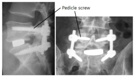
Figure 1.
Radiographs after a lumbar interbody fusion surgery for degenerative disc disease.
During surgery, pedicle screws and a linking mechanism are applied to two or more lumbar vertebrae (for example, L4 and L5). Pedicle screws are usually used in surgery to correct problems with the spine. The basic idea is to fasten two or more vertebrae together to alleviate spinal distortion, stabilize the spine, and improve its strength. The screws play an essential role in providing additional support and strength through the surgery.
Although spinal fusion with pedicle screws is a good way to treat spinal problems, several failure modes and the efforts to overcome them have been reported. Failure can be due to screw loosening and pull-out, as well as fatigue fracturing [4]. Loosening and pull-out are due to failures in the early stages after the surgery, but the fatigue fractures are due to failure after a certain post-operative period due to toggling with cyclic loading and occur at the pedicle screw on the caudal side. If two or three of the factors are compounded, more tragic situations can arise, and so it is necessary to solve the problematic factors at an early stage. Meanwhile, several shapes and characteristics of the pedicle screws have been suggested to address these failure modes.
Pedicle screws and a linking mechanism are commonly used in spinal fusion surgery. This assembly is secured to the vertebrae and spine by using the pedicle screws. The pedicle screw is invasively implanted into the vertebrae and then becomes osteo-integrated with the bones. Therefore, it is important to avoid failure of this component. From an engineer’s point of view, the parts that cannot be disassembled or repaired require more comprehensive design and evaluation. In recent years, with the development of the above-mentioned components and surgery, failure of the screws, other than as a result of fatigue fracturing, rarely occurs. Nevertheless, the first step in the mechanical design of a screw is testing how it withstands static loading. After the static strength test, fatigue testing under repeated loads is usually investigated.
The causes of failure of pedicle screws are various and due to factors, such as pedicle fill, bone density, and the shape and mechanical properties of the screw. If the diameter of the screw is too small compared to the pedicle width, it bends too easily and cannot withstand pull-out loading [6]. When the bone density of the vertebrae is low, there is a high probability that the screw will become loose and thus the pull-out strength is also lowered. Moreover, the strength of the screw is weak if it is too long or has an excessively tapered minor diameter. When the strength and stiffness of the screw material are not enough, bending strength and pull-out strength are also low. Several improved designs that take these factors into account have been reported, such as dual screws with single and double threads [7]. The opinion of field clinicians is that the use of the dual screw significantly reduces problems after implantation. Nevertheless, because many manufacturers still want to develop alternative pedicle screws, their pedicle fill, shape, and properties are to be determined by a rigorous design procedure. To release a new product, it is first necessary to evaluate its reliability under the new design conditions.
Although several studies have obtained useful results, they were limited because the improvement of screw design or the analysis of vertebrae has been considered separately. Mummaneni et al. [8] compared the pull-out strengths of different screw designs, while Yoo et al. [9] explored the strength with several screw leads and Ahn et al. [10] investigated the cause of the breakage of the thoracic and lumbar vertebrae due to the screw insertion method. Despite these efforts, the biomechanical models generated in most studies has been concerned separately for vertebrae or pedicle screws instead of creating an integrated model that takes into account the interactions between them. In particular, standard tests and detailed analysis models must be combined to solve problems that arise at an early stage after surgery. This should comprise a comprehensive platform to understand the interaction between the vertebrae and pedicle screws and to investigate their behavior after the surgery. This will allow researchers to evaluate or verify the design of alternative pedicle screws.
Therefore, herein, a comprehensive platform based on experimental effort and coordinated modeling is presented. Moreover, the platform was applied to evaluate an alternative dual pedicle screw design with varying shapes and dimensions. The structural stability of the screws was evaluated via testing based on the ASTM F1717 standard. An integrated finite element analysis (FEA) model of vertebrae and screws was also established to investigate their mechanical stresses and interactions. Finally, we present the efficacy of the design platform by the alternative dual screw design results.
2. Alternative Pedicle Screw Design
The spine plays an essential role in supporting the human body, and the characteristics of vertebrae depend on age, race, and gender. Their appearance varies depending on their location (i.e., in the cervical, thoracic, and lumbar spine). The length, diameter, pitch, and type of screw are important and must be determined thoroughly. Furthermore, the linking mechanism between the screw and vertebrae is equally important [11] but is not covered in this work.
The fusion structures among the vertebrae, screws, and links should be able to support varying loads on the spine. In general, the movement of the human body causes bending and tensile forces to be applied to the fusion structures, and so the inserted pedicle screws should be strong enough to withstand bending forces and should not be pulled out easily by tensile forces. In addition, stress concentration can damage the fusion structures; therefore, stress due to applying a load must be distributed throughout the screw volumes.
Over the past few decades, a single thread has been applied most often because of its simplicity (Figure 2a). A single-threaded screw has a head, shank, and tapered thread with one type of pitch and lead. This screw has a much shorter lead compared to its full inserting depth and so it should be tightened repeatedly during the surgery. In general, if the screw is repeatedly tightened, a lot of shear stress is repeatedly applied to the cross-section between the head and the shank and thus shear fracture is likely to occur. The repeated tightening also causes discomfort to the surgeon during the surgery.
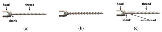
Figure 2.
Various pedicle screws: (a) single, (b) double, (c), and the proposed thread.
When the double screw in Figure 2b is applied, the operation time is shortened and the convenience to the surgeon is improved because of the insertion depth (i.e., the lead of the screw is twice per rotation). The double thread has a longer pitch and twice the lead of the single screw, thereby reducing the number of turns during an operation. However, this design is likely to be vulnerable to bending or tensile loading on the spine during normal human activity because the longer pitch results in a smaller cross-section of the screw. The ease of screw insertion means that it can be easily unfastened by human motion, which is a disadvantage that lowers the stability of the fused structure after surgery.
In a previous study, dual pedicle screws were proposed with single and double threads. More recently, quadruple threads were also applied to this dual screw [7]. Although this design is used clinically with few problems, there are reports that the pull-out strength of the dual screw is weaker than that of a screw with a single thread [12]. If the taper from one thread to the other is not designed to run smoothly, stress can become concentrated under loading, resulting in lower bending or pull-out strength, and can lead to fatigue failure [5]. In addition, there have been many studies focusing on the structural stability of various pedicle screw design. This study shows a meaningful outcome, such as insertion torque and pullout stiffness for each design using cadaveric thoracolumbar spines [13]. However, the researchers found it difficult to produce a detailed design and evaluation methodology for a double screw with quadruple threads. In addition, in the analysis of the conventional dual screw, the stress concentration on the vertebrae and the screw was not analyzed in detail. Therefore, for future screw development, it is necessary to propose a design and evaluation platform that can analyze the stress on the vertebrae and screws together, the vertebrae only, and the screws only. The platform should enable us to carry out tests and analyses concurrently.
For this paper, an alternative pedicle screw (Figure 2c) was designed and evaluated via the design platform. This was an improved hybrid screw compared to the commercially available screws [7]. The product ‘Dual lead OSTEOGRIP®’, which is produced by Medtronic, was similar to the alternative pedicle screw studied in this work. The alternative was longer and thinner than the commercialized product. The product does not have a marked length difference between the two threads, whereas the alternative had a long main thread compared to its sub-thread. These can show different structural behaviors, such as stress concentration, tensile strength, and fatigue compared to the commercialized product. In fact, the shape and dimensions of the alternative were modified to relax the stress concentration. The screw had a shank, sub-thread, and main thread from the head to the tail. The contour from the head to the shank was a smooth curve, because stress concentration can occur if this is inappropriate. The shank was designed to be shorter than current pedicle screws to make it stronger, because the shorter length gives higher stiffness against loading due to torque, bending, and tension. In addition, the sub-thread had a finer pitch, which results in a larger cross-section of the screw, which makes the tensile stress area wider so that the screw can support higher loads. The finer pitch prevents loosening. Furthermore, the sub-thread had a quadruple thread and the main thread was a double thread, which both helped to reduce the surgery time.
Thus, the alternative screw design with quadruple and double threads was robust against fracturing of the shank and minimized surgical inconvenience. Despite the previous study’s improvement, the stress concentration should be relaxed more in the transition section between the main thread and the sub-thread. The connection between the double and quadruple screws was designed to be smooth with no discontinuity. The cross-sectional changes between them were smoothly tapered. In this hybrid design, the stress concentration due to loading was investigated both experimentally and via FEA. The overall structural robustness of the design was also analyzed by considering the attachment of the screw to the vertebrae.
3. Mechanical Strength of the New Design
The main loads due to human activity are due to bending and tension, and failure of the pedicle screws caused by them is due to fracturing by bending and pull-out by tensile loading. To investigate the strength of the screw, special experiments were conducted to analyze bending conditions and FEA simulations were performed to assess tensile loading. Experimental and FEA tests on the conventional single- and double-threaded screws and the proposed pedicle screw were performed. The detailed dimensions of the tested screws are reported in Table 1.

Table 1.
Detailed dimensions of the tested screws.
The pedicle screw in this study had a diameter of 4.5 mm. In general, the outer diameter of pedicle screws ranges from 4 to 7 mm, and the selection of a proper pedicle screw diameter must be based on the morphology of the spinal pedicle. Therefore, it is difficult to define a representative pedicle screw diameter. In fact, the mechanical behavior of screws with other diameters is easily predictable because screws with different diameters perform analogously. In the present study, the effect of screw insertion was not addressed because pedicle screw insertion was assumed to be accomplished appropriately and the osseointegration was perfect even though the insertion could affect the clinical outcome.
3.1. Experimental Testing of Bending Strength
3.1.1. Experimental Setup
Experimental tests were performed based on the ASTM F1717 standard [14]. The model fused structure consisted of two vertebrae, four pedicle screws, and a linking mechanism. The model vertebrae with a pentagonal top view were made from ultra-high molecular weight polyethylene (UHMWPE) because of its high toughness and good self-lubrication, which are good characteristics for the bending test jig [15]. The pedicle screws were fastened to the model vertebrae and tightened with appropriate torque using a torque wrench [16]. The distance between the top and bottom screws was 76 mm, which is similar to the actual distance between two human vertebrae. The linking mechanism (two rods) was inserted into the U-shaped groove of the screw head.
The prepared test mechanism can be seen in Figure 3. Cubic top and bottom jigs were also assembled with the model structure, fused by using two pins that allowed free rotation without resisting movement (Figure 3a). Each of the fixtures was placed in a material testing machine (MTS 858 Table Top System, MTS System Corp., USA; Figure 3b); the bending tests were performed by pressing the jigs at a rate of 25 mm/min until fracturing occurred. In all tests, the compression distance and load were recorded (especially the load that caused fracturing).
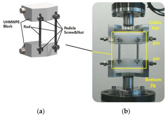
Figure 3.
Experimental setup for bending strength testing: (a) The fused structure and (b) the material testing machine with the structure.
3.1.2. Experimental Results and Discussion
The pressing load for the compression distance is shown in Figure 4. Table 2 shows the loads at the point of rupture for the two conventional screws and the alternative screws, respectively. Each thread was tested six times. As shown in Figure 4, when the load exceeded 160 N and the squeezed distance was more than 5 mm, the slope of the double thread was changed abruptly. From the results of Table 2, it is clear that a failure occurred near the load 160 N. Although this tendency was not clear with the single or proposed threads, it can be seen that there were also fractures at loads of 250–260 N and a compression distance of 10 mm.
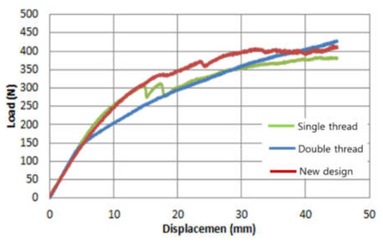
Figure 4.
Typical bending test results: Pressing load vs. compression distance.
Table 2.
Bending test results: strength vs. bending.
The double thread was vulnerable to bending loads despite the reduction in operation time. This is because it had a longer pitch (p) and twice the lead compared to the single screw, leading to a reduced number of turns during an operation. The double thread’s basic diameter (dbasic), length, and shape were similar to those of the single thread, but the root of the thread got deeper, which made the effective cross-section of the screw smaller than that of the single screw because its pitch was longer.
This was because the longer pitch makes the tensile stress area narrow, as follows [17]:
where k1 and k2 are specific constants from the screw shape and dimensions. The small area led to weak strength against bending and loading.
The alternative design showed the highest strength during bending loading in the experimental tests. The bending resistance of the alternative design was more than 55% higher than that of the conventional double-threaded screw. Thus, even though using it is convenient during surgery, it is difficult to apply it when it has such low strength. The alternative design was 12% stronger than the conventional single thread, although the difference was within the range of one standard deviation. However, the bending resistance of the alternative screw was similar to that of the conventional single thread but required fewer turns during surgery. Therefore, we can conclude that the alternative thread is a good solution for a pedicle screw from a bending resistance perspective.
3.2. Numerical Testing for Pull-Out Strength
Since pull-out strength is important in a pedicle screw design, various evaluation methods have been proposed to test it. It is noteworthy that previous researchers measured the pull-out force after applying the pedicle screw on a polyurethane block or bovine bone [4]. Others have investigated the force required after embedding in various polyurethane blocks to simulate the diverse bone density conditions of the vertebrae. The ASTM F1839 standard [18] was mainly used to assess these methods. Other testing methods using the ASTM F543-13 standard have been reported. As a vertebra model material, UHMWPE was applied. Real human bone can also be used in the tests.
However, the polymers characteristics are not compatible with the pull-out test because they are more mechanically compliant (Young’s modulus ~30 MPa) [19] than human bone (Young’s modulus ~100 MPa). Additionally, it is difficult to perform every required experiment for a screw design with real vertebrae because it is difficult to obtain actual human spine bones. Moreover, it can only evaluate the results of the testing and it is not possible to know in detail the stress distributed in the screw, the lumbar spine, or both. As described above, when a pull-out or bending load is applied to the pedicle screw, static rupturing or fatigue fracturing mainly occurs in the region where the stress is concentrated. Therefore, analyzing the distribution of stress in a screw, vertebrae, or both is important for design improvement.
There is an example study of modeling the pedicle screw via an FEA method. The researchers analyzed the pull-out strength according to the angle or depth at which the screw was mounted on the vertebrae and reported that the strength changed with the varying bone density in the spine [20]. In addition, an example of using the FEA method to predict the results after inserting intramedullary devices into the femur and hip joint to treat hip fracture was reported [21]. Based on these studies, strength analysis of the pedicle screw, vertebrae, and both together, using FEA, has become a general method. Therefore, it would be helpful to researchers in the future if a platform of modeling and experimental testing became established so that design improvement and reliability evaluation were possible.
Therefore, in this study, an FEA model of the integrated structure comprising vertebrae (L4 and L5) and inserted screws was established and then applied to assess the structural stability of the alternative screw against the pulling-out force. A few ASTM standards and several studies on pull-out testing were consulted to define the applied load in the FEA model [4,19,22].
3.2.1. Establishment of the FEA Model
Among the integrated models, the lumbar vertebra model was derived from computed tomography (CT). A typical adult L4 was scanned using CT with a constant thickness of 1 mm, and the three-dimensional (3D) structure was obtained by processing the image. The CT image data was used to extract vectorized images of the outer and inner boundaries of each section. Figure 5 shows the 3D structure of L4. The vertebra consists of a gray posterior element and a yellow disk. The posterior elements are composed of pedicles, transverse processes, facet joints, and spinous processes.
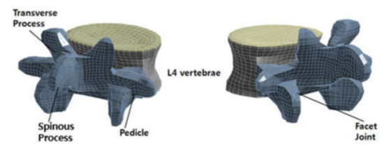
Figure 5.
Three-dimensional (3D) structure for the L4 vertebra FEA model.
Lumbar vertebrae comprise various materials: a dense outer layer of cortical bone (1 mm thick) and internal cancellous bone. The posterior elements are more flexible than the cancellous bone. The disk has an external cortex and the top and bottom endplates. The endplates are thin cartilage tissue (1 mm thick). The material is assumed to be homogeneous and isotropic. [23,24]. Table 3 reports the properties of the material.
Table 3.
Material properties of the lumbar vertebrae in the finite element analysis (FEA) model.
The 8-node hexahedral elements were used to generate meshes in the disk. The meshes have concave curved shapes to exactly match the undulating surface of the disk. Eight-node hexahedron and six-node tetrahedral elements were applied to create meshes in the posterior elements. This combination of meshes matched the complex shape of the posterior element.
To integrate the lumbar model with the pedicle screw model, a cavity was created in L4 that fully coincided with the screw, after which the pedicle screw model was inserted into the cavity. The cavity was oriented at 30° from the center of the pedicle to the disk. Since complete osseointegration was assumed, the tie-contact condition was applied to the interface between the bone and the screw. The element type of the screw was a 10-node tetrahedron, which is a general type of FEA solver. The material of the pedicle screw was a biocompatible titanium alloy (Ti-6Al-4V ELI), the material properties of which are summarized in Table 4 [25]. The number of nodes and elements in all of the unified models was 106,582 and 57,938, respectively. The integrated model is shown in Figure 6.
Table 4.
Material properties of the pedicle screw.
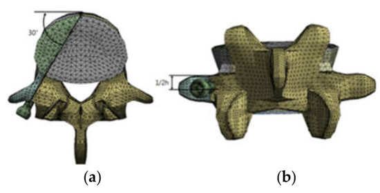
Figure 6.
Integrated FEA model with L4 and pedicle screws: (a) Top view with insertion angle and (b) posterior view with insertion location.
Each node on the upper and bottom endplates was constrained to apply pull-out force that mimics the tensile force during human spine movement. In addition, 600 N of pull-out force was applied to the pedicle screw head in the direction from the cavity to the screw head. These forces are shown in Figure 7.
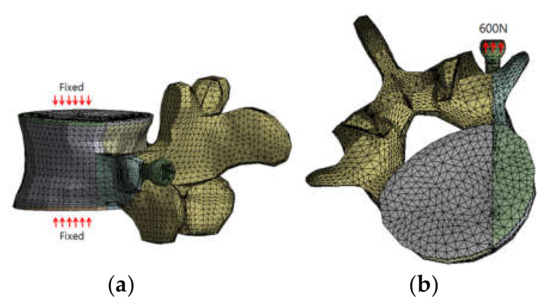
Figure 7.
Simulation conditions: (a) the boundary conditions and (b) the loading conditions for the pull-out force.
3.2.2. FEA Results and Discussion
The established FEA model was used to evaluate the stress state of the lumbar vertebrae and the pedicle screw. Three types of pedicle screws were used in the analysis, the results of which were compared with each other (Figure 8, Figure 9 and Figure 10 and Table 5).
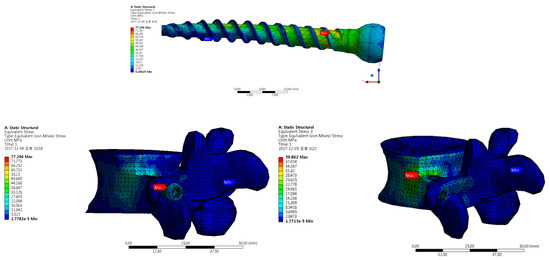
Figure 8.
FEA results for a single-threaded pedicle screw: Top is the pedicle screw, left is L4 and the pedicle screw, and right is L4.
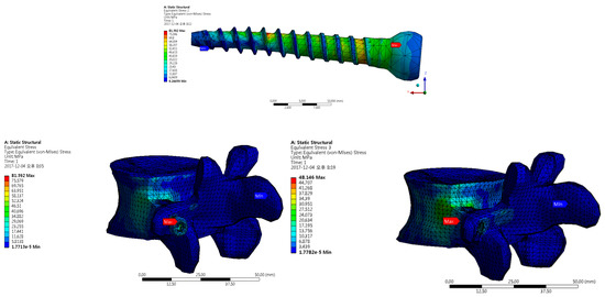
Figure 9.
FEA results for the double-threaded pedicle screw: Top is the pedicle screw, left is L4 and the pedicle screw, and right is L4.
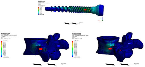
Figure 10.
FEA results for the proposed pedicle screw: Top is the pedicle screw, left is L4 and the pedicle screw, and right is L4.
Table 5.
FEA analysis results.
In the integrated model, resistance to pull-out force is mainly given by the pedicle screw, with some by the bone. The maximum Von–Mises stress in the model matched that on the screw surface. However, the maximum Von–Mises stress calculated at the proximal part of the pedicle was approximately half of that for all of the integrated models. This means that the maximum stress on the screw surface was generated and transmitted to the pedicle and then to the vertebra.
For all three models, the magnitudes of the stress against the pull-out force were allowable because they did not exceed the strength of each material. The maximum stress in the pedicle screws was smaller than the strength of Ti-6Al-4V ELI (900 MPa), while the stress at the proximal part of the pedicle decreased by 52%, 59%, and 44% from the maximum for the single-threaded, double-threaded, and proposed designs, respectively. Hence, the maximum stress in L4 was lower than the cortical bone’s strength (50–150 MPa) [26]. Therefore, it can be concluded that the three types of pedicle screws showed appropriate mechanical robustness against the pull-out force and had appropriate stress distribution from the screw to the bone.
We can conclude that the alternative dual screw design is appropriate for improved convenience during surgery and, even though the screws were slightly more stressed than the others, their mechanical robustness values were similar. However, the alternative screw design could be improved to lower the stress concentration and maximum stress. In all the analysis results, the maximum stress on the vertebrae occurred properly in the cortical bone, which is a deep region of the spine. The maximum stresses on the pedicle screw all appeared in the shank between the head and the thread due to the stress concentration caused by the sudden change in the cross-sectional area of the screw from the head to the shank. Therefore, design modification is needed to ensure that the cross-sectional area from the head to the shank changes more gradually and smoothly. The alternative pedicle screw incurs around 20% more stress than the conventional designs. This means that the stress on the quadruple thread underneath the shank is higher, which in turn increases the stress on the shank as a whole. The stress could be lowered if a somewhat longer quadruple thread was employed in the alternative dual thread.
4. Discussion and Conclusions
In a previous study, the ASTM F1717 standard was used to compare the bending strength of polyaxial pedicle screws embedded in a polyurethane block that mimicked vertebrae. Their test results were similar to the results of the present study, as shown in Figure 4 [27]. Therefore, the presented method is considered appropriate. There have been examples of measuring the pull-out strength of several types of pedicle screws, varying from 420 to 1676 N [4,20]. It is difficult to directly compare these results with this study because the formers were not obtained using an FEA model. However, there has been a report that standard pedicle screws can withstand more than 796 N [20]. When considering safety, it is meaningful to analyze the pull-out characteristics under loading of 600 N in the proposed FEA model.
The alternative design of a pedicle screw for spinal fusion was introduced and a design platform was constructed to improve structural robustness and surgical convenience, which was confirmed by a combined experimental and analytical approach. The alternative pedicle screw consisting of a head, shank, sub-thread, and main thread was based on modifying conventional pedicle screws to enhance the convenience of their use during surgery and their structural robustness. The smooth contours, short shank, and fine pitch increased their mechanical strength, while the quadruple thread adopted as a sub-thread could reduce the surgery time.
A series of experiments was carried out on each screw to investigate the bending strength. The alternative design showed the highest resistance against bending load, which was more than 55% higher than the pedicle screw with a conventional dual thread. For the pull-out resistance, an FEA model was first established and then the stress distribution of each screw was investigated. The stress value of the alternative pedicle screw was certainly acceptable because it was below the strength of each material. However, the design could be modified by a gradual change of the cross-sectional area and longer quadruple thread to lower the generated stress under loading.
The alternative design can effectively resist bending and pull-out loadings. Moreover, the generated stress can be lowered via a small modification of the design to change the cross-sectional area gradually and employ a longer quadruple thread. Therefore, it can be concluded that the alternative dual screw design could be a more appropriate design for spinal fusion.
The alternative pedicle screw was designed and evaluated using the proposed comprehensive design platform, which makes it possible to simultaneously improve the bending and pull-out strength. Moreover, the stress distribution on the vertebra and screw, and both together, can be closely analyzed. This plays an important role in predicting and improving problems that can occur at an early stage after surgery, as well as the fatigue issue that can occur after a somewhat longer time after the surgery. Moreover, the platform can be used to optimally design other medical devices in the future.
Author Contributions
Conceptualization, M.H.H. and M.G.L.; methodology, M.H.H.; validation, J.K. and M.H.H.; formal analysis, M.H.H.; writing—original draft preparation, J.K.; writing—review and editing, M.G.L.; supervision, M.G.L. All authors have read and agreed to the published version of the manuscript.
Funding
This work was supported by the National Research Foundation of Korea (NRF) grant, funded by the Korean Government (MSIT) (NRF-2018R1A2B2002683).
Conflicts of Interest
The authors declare there are no conflicts of interest.
References
- Lee, Y.C.; Zotti, M.G.T.; Osti, O.L. Operative Management of Lumbar Degenerative Disc Disease. Asian Spine J. 2016, 10, 801–819. [Google Scholar] [CrossRef]
- Taylor, V.M.; Deyo, R.A.; Cherkin, D.C.; Kreuter, W. Low back pain hospitalization: Recent United States trends and regional variations. Spine 1994, 19, 1207–1213. [Google Scholar] [CrossRef] [PubMed]
- Iorio, J.A.; Jakoi, A.M.; Singla, A. Biomechanics of Degenerative Spinal Disorders. Asian Spine J. 2016, 10, 377–384. [Google Scholar] [CrossRef] [PubMed]
- Yaman, O.; Demir, T.; Arslan, A.K.; Iyidiker, M.A.; Tolunay, T.; Camuscu, N.; Ulutas, M. The comparison of pullout strengths of various pedicle screw designs on synthetic foams and ovine vertebrae. Turk. Neurosurg. 2015, 25, 532–538. [Google Scholar] [PubMed]
- Chen, C.-S.; Chen, W.-J.; Cheng, C.-K.; Jao, E.S.-H.; Chueh, S.-C.; Wang, C.-C. Failure analysis of broken pedicle screws on spinal instrumentation. Med. Eng. Phys. 2005, 27, 487–496. [Google Scholar] [CrossRef] [PubMed]
- Albanese, K.; Ordway, N.R.; Albanese, S.A.; Lavelle, W.F. Effect of Pedicle Fill on Axial Pullout Strength in Spinal Fixation After Rod Reduction. Orthopedics 2017, 40, E990–E995. [Google Scholar] [CrossRef][Green Version]
- Gary, K.; Michelson, M.D. CD HORIZON® SOLERA™ Spinal System Surgical Technique; Medtronic: Memphis, TN, USA, 2009. [Google Scholar]
- Mummaneni, P.V.; Haddock, S.M.; Liebschner, M.A.; Keaveny, T.M.; Rosenberg, W.S. Biomechanical evaluation of a double-threaded pedicle screw in elderly vertebrae. J. Spinal Disord Tech. 2002, 15, 64–68. [Google Scholar] [CrossRef]
- Yoo, M.C.; Lee, S.U.; Kim, K.T.; Sun, S.D.; Kim, I.Y.; Moon, M.S. A Biomechanical study on the fixation strength of the trans-pedicular screw: In vitro measurement. J. Korean Orthop. Assoc. 1995, 30, 459–469. [Google Scholar] [CrossRef][Green Version]
- Ahn, M.W.; Han, J.H.; Koo, J.W.; Chung, S.M.; Cho, J.H. Morphologic feasibility of pedicle screw insertion in Korean. J. Korean Orthop. Assoc. 2007, 42, 255–263. [Google Scholar] [CrossRef]
- Dick, J.C.; Jones, M.P.; Zdeblick, T.A.; Kunz, D.N.; Horton, W.C. A biomechanical comparison evaluating the use of intermediate screws and cross-linkage in lumbar pedicle fixation. J. Spinal Disord Tech. 1994, 7, 402–407. [Google Scholar] [CrossRef]
- Bianco, R.J.; Arnoux, P.J.; Wagnac, E.; Mac-Thiong, J.M.; Aubin, C.É. Minimizing Pedicle Screw Pullout Risks: A Detailed Biomechanical Analysis of Screw Design and Placement. Clin. Spine Surg. 2017, E226–E232. [Google Scholar] [CrossRef]
- Mehta, H.; Santos, E.; Ledonio, C.; Sembrano, J.; Ellingson, A.; Pare, P.; Murrell, B.; Nuckley, D.J. Biomechanical analysis of pedicle screw thread differential design in an osteoporotic cadaver model. Clin. Biomech. 2012, 27, 234–240. [Google Scholar] [CrossRef] [PubMed]
- ASTM F1717-04. Standard Test Methods for Spinal Implant Constructs in a Vertebrectomy Model; ASTM International: West Conshohocken, PA, USA, 2004.
- Wikipedia. Available online: https://en.wikipedia.org/wiki/Ultra-high-molecular-weight_polyethylene (accessed on 7 May 2020).
- Ozawa, T.; Takahashi, K.; Yamagata, M.; Ohtori, S.; Aoki, Y.; Saito, T.; Inoue, G.; Ito, T.; Moriya, H. Insertional torque of the lumbar pedicle screw during surgery. J. Orthop. Sci. 2005, 10, 133–136. [Google Scholar] [CrossRef]
- ASME B1.13M. Metric Screw Threads: M Profile; ASME International: New York, NY, USA, 2005.
- Varghese, V.; Kumar, G.S.; Krishnan, V. Effect of various factors on pull out strength of pedicle screw in normal and osteoporotic cancellous bone models. Med. Eng. Phys. 2017, 40, 28–38. [Google Scholar] [CrossRef]
- Dayyoub, T.; Maksimkin, A.V.; Kaloshkin, S.; Kolesnikov, E.; Chukov, D.; Dyachkova, T.P.; Gutnik, I. The structure and mechanical properties of the UHMWPE films modified by the mixture of graphene nanoplates with polyaniline. Polymers 2019, 11, 23. [Google Scholar] [CrossRef] [PubMed]
- Matsukawa, K.; Yato, Y.; Hynes, R.A.; Imabayashi, H.; Hosogane, N.; Yoshihara, Y.; Asazuma, T.; Nemoto, K. Comparison of Pedicle Screw Fixation Strength Among Different Transpedicular Trajectories. Clin. Spine Surg. 2017, 30, 301–307. [Google Scholar] [CrossRef]
- Kim, J.-T.; Jung, C.-H.; Shen, Q.H.; Cha, Y.-H.; Park, C.H.; Yoo, J.-I.; Song, H.K.; Jeon, Y.; Won, Y.-Y. Mechanical Effect of Different Implant Caput-Collum-Diaphyseal Angles on the Fracture Surface After Fixation of an Unstable Intertrochanteric Fracture: A Finite Element Analysis. Asian J. Surg. 2019, 42, 947–956. [Google Scholar] [CrossRef] [PubMed]
- ASTM F543-17. Standard Specification and Test Methods for Metallic Medical Bone Screw; ASTM International: West Conshohocken, PN, USA, 2013.
- Goel, V.K.; Monroe, B.T.; Gilbertson, L.G.; Brinckmann, P. Interlaminar shear stresses and laminae separation in a disc. Finite element analysis of the L3-L4 motion segment subjected to axial compressive loads. Spine 1995, 20, 689–698. [Google Scholar] [CrossRef] [PubMed]
- Shirazi-Adl, S.A.; Shrivastava, S.C.; Ahmed, A.M. Stress analysis of the lumbar disc-body unit in compression. A three-dimensional nonlinear finite element study. Spine 1984, 9, 120–134. [Google Scholar] [CrossRef]
- Niinomi, M. Mechanical properties of biomedical titanium alloys. Mater. Sci. Eng. 1998, 243, 231–236. [Google Scholar] [CrossRef]
- Rezwan, K.; Chen, Q.Z.; Blaker, J.J.; Boccaccini, A.R. Biodegradable and bioactive porous polymer/inorganic composite scaffolds for bone tissue engineering. Biomaterials 2006, 27, 3413–3431. [Google Scholar] [CrossRef] [PubMed]
- Walsh, W.; Loefler, A.; Stanford, R.; Stanford, P.; Svehla, M.; Sutiono, T. Mechanical Analysis of Polyaxial Pedicle Screws using ASTM F1717. In Proceedings of the 46th Annual Meeting, Orthopaedic Research Society, Orlando, FL, USA, 12–15 March 2000. [Google Scholar]


© 2020 by the authors. Licensee MDPI, Basel, Switzerland. This article is an open access article distributed under the terms and conditions of the Creative Commons Attribution (CC BY) license (http://creativecommons.org/licenses/by/4.0/).