1. Introduction
Cycloid drives have been widely applied in many industrial areas for speed, torque conversion purposes, and precision pointing, such as in robots, machine tools, and wind power, since they were invented by Mr. Lorenz Braren in the 1930s.
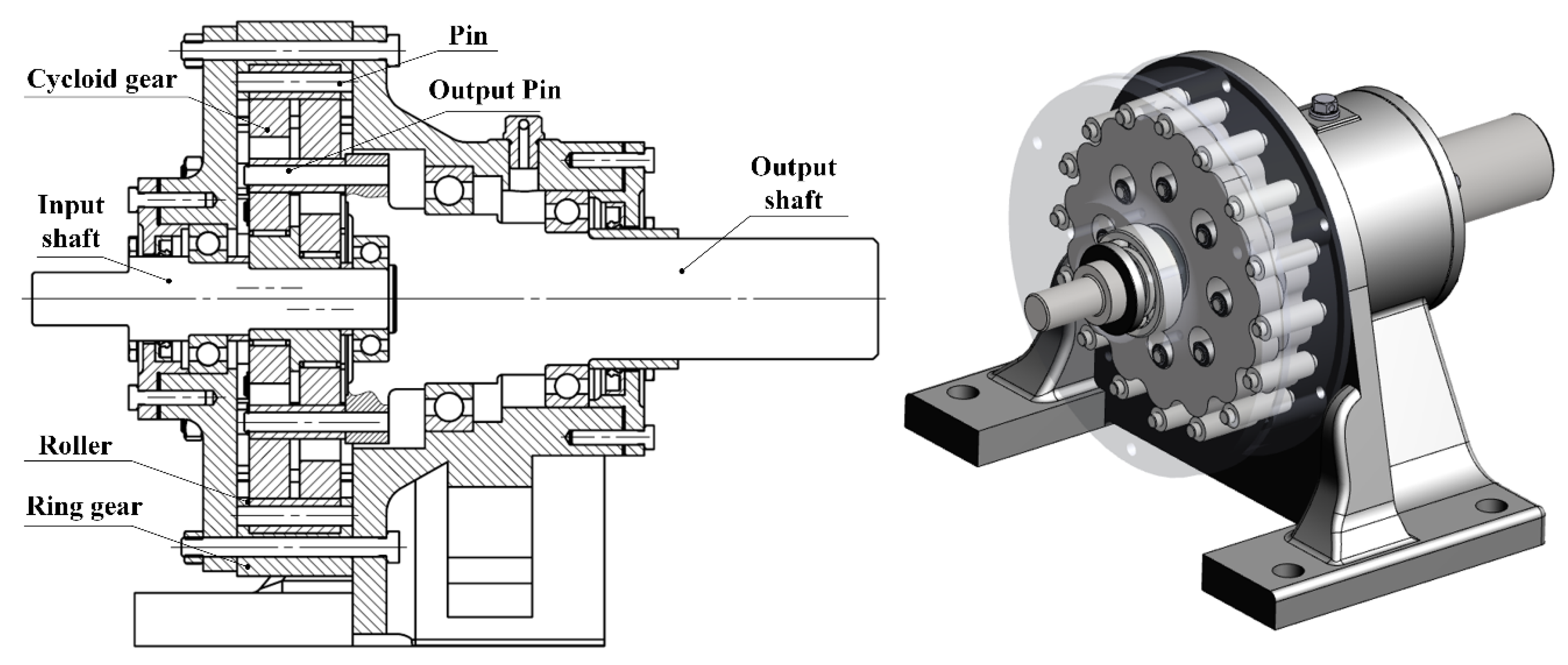
Figure 1 illustrates the typical structure of a single-stage cycloid drive with its main elements including two cycloid gears, several rollers, crankshaft, and output mechanism. It is a complicated eccentric-rotation-type planetary transmission mechanism, which is unlike the more commonly understood involute gearing. The small tooth number difference and multi-tooth contact characteristics give cycloid drives the advantages of compact size, light weight, large gear ratio, high positioning precision, and high load carrying capability [
1,
2]. Despite these benefits, as of now, many design problems of cycloid drives have not been solved, and no known design standards for cycloid drives are available [
3,
4]. In particular, taking the effects of both the tooth profile and longitudinal modifications into consideration, the contact strength calculation and transmission accuracy prediction of this gear drive have not been reported in the literature. This is partially due to the difficulty of the backlash determination between two tooth surfaces, the establishment of multi-tooth contact deformation compatibility, and the complexity of ever-changing magnitudes and directions of loads among the tooth pairs with different mesh phases over the mesh cycle [
5].
To provide some guidelines for the optimal design of cycloid drives, many research works have focused particularly on the load distribution analysis of cycloid drives, as well as further influence analysis of tooth profile modification. Malhotra and Parameswaran [
6] developed a method to compute the load distributed on various components of a speed reducer based on the assumption of perfect geometry and rigid bodies of gears. Blagojevic et al. [
7] presented a new two-stage cycloid speed reducer and developed a method for force analysis based on Malhotra’s method. Gorla et al. [
8] proposed a calculation procedure to predict the loads distributed on the elements of a new cycloid speed reducer, and an experiment was performed to validate the prediction results. Wang et al. [
9] proposed a tooth contact analysis model for an RV reducer by dividing the contact area into several differential elements to demonstrate the effects of the tooth profile modification and load on the transmission precision, mechanical properties, and transmission efficiency. Xu et al. [
10,
11] proposed a contact dynamics model to analyze the contact dynamics of the KHV-type cycloid speed reducer while considering the effects of a turning-arm cylindrical roller. Sun et al. [
12] proposed a new tooth contact analysis (TCA) method based on the discrete point tooth profile for a new type of CBR (China Bearing Reducer) reducer. By using the new TCA model, the transmission error and contact force of the designed reducer can be predicted with different modified methods. Li et al. [
13,
14] proposed a meshing contact analysis method for RV cycloidal-pin gear transmission considering the effect of manufacturing errors. Li et al. [
5,
15] presented an analytical model for the KHV-type cycloid drive considering clearances of the cycloid gear pair and output mechanism at a system level, and they also proposed a mesh stiffness calculation method for cycloid gear pairs considering the tooth profile modifications and eccentric error. Sensinger et al. [
16] considered that the cycloid profile may be generated by reducing the roller position to change the tips and roots of the tooth profile and qualitatively showed the difference between the topographic profiles modified by roller position and by roller radius. Lin et al. [
17] investigated cycloid tooth profile modification quantitatively under individual and combined conditions. Lin et al. [
18] developed a kinematic error analysis method and tolerance design procedure for cycloidal gear reducers considering geometry, manufacturing, and precision performance.
A review of the literature reveals that the current analytical methods for cycloid drives typically assume a two-dimensional planar problem without considering the tooth longitudinal modification effects, which fails to comply with the practical situation. In fact, the cycloid gear will be crowned to relieve the stress concentration occurring on the tooth edges, which will lead to serious contact failure of the cycloid drive. Therefore, the aim of this paper is to propose a computationally efficient, semi-analytical load distribution model for cycloid drives based on a three-dimensional and linear elastic solution while considering both the tooth profile and longitudinal modifications. It will have the ability to simulate quasi-statically the multi-tooth contact conditions and determine the contact stress and pattern, loaded transmission error, and gear ratio of cycloid drives. Another purpose of this paper is to propose several types of tooth longitudinal modifications of cycloid gear teeth to improve the contact stress distribution conditions by using the proposed model.
The rest of this paper is structured as follows:
Section 2 presents the tooth surface geometry of the cycloid gear, its generation method is introduced, and several types of tooth profile and longitudinal modification are proposed.
Section 3 presents the semi-analytical load distribution model based on the unloaded and loaded tooth contact analyses. In this section, the tooth compliance model is established by combining the Boussinesq force–displacement relationships in elastic half-space with an influence coefficient method.
Section 4 gives a numerical example to verify the proposed model by comparison with the prediction results of the current model based on the Hertz contact stiffness method. The effects of tooth profile, longitudinal modifications, and applied torque levels on the contact stress and pattern, loaded transmission error, and gear ratio are investigated by using the proposed model. Finally, conclusions are drawn in
Section 5.
3. Load Distribution Model
In this section, a new load distribution model for cycloid drives is proposed, which is treated as a three-dimensional elastic body contact problem to demonstrate the effects of both the tooth profile and longitudinal modifications accurately. This semi-analytical model is developed and analyzed under the following assumptions:
The load distributed on one tooth pair does not affect elastic deformations on adjacent tooth pairs.
The rotational speed and inertia forces of moving elements are neglected in the quasi-static process.
The curvature of the gear tooth surface over the contact region is assumed to remain unchanged.
The friction between contacting tooth pairs is neglected.
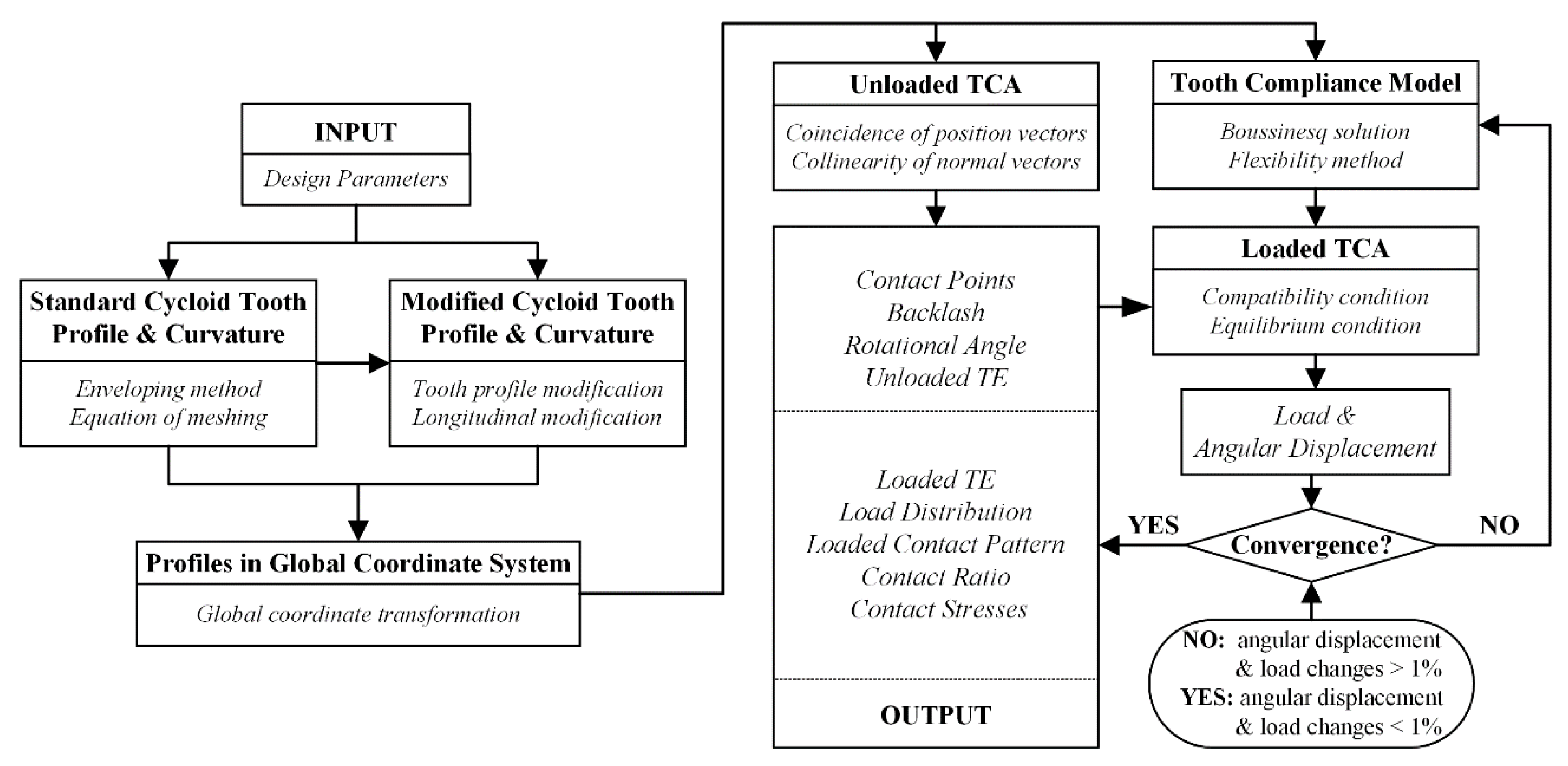
With the above assumptions, the overall methodology for the proposed semi-analytical model is shown in
Figure 5. The design dimensions, modification amounts, material properties, and applied torque are the input parameters for the proposed model. The cycloid gear tooth and roller profiles described by these parameters are transformed to a global coordinate system to perform the unloaded tooth contact analysis (TCA) and to determine the backlash, unloaded transmission error, contact points, and rotational angle in a mesh circle. Next the tooth compliance model considering tooth contact deformation is developed by combining the Boussinesq force–displacement relationships in elastic half-space with an influence coefficient method. Finally, a group of equilibrium and compatibility conditions are given and solved to calculate the loads, contact stress, contact pattern, loaded transmission error (TE), and gear ratio of the cycloid drive.
3.1. Unloaded Tooth Contact Analysis
The unloaded tooth contact analysis (TCA) is developed in the two-dimensional plane in order to instantly determine the instantaneous central points of potential contact regions.
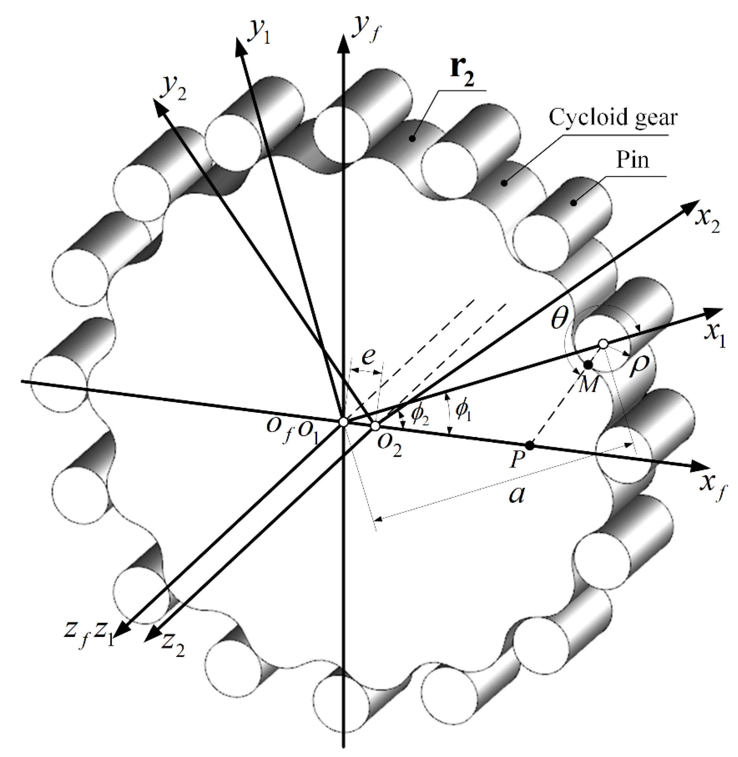
Figure 6 shows the coordinate systems for unloaded TCA.
and
are connected rigidly with the pinwheel and cycloid gear, and the fixed coordinate system
coinciding with
is fixed to the housing. Hence, the position vector
and its unit normal vector
of all the roller profiles can be expressed in
:
where
is the number of rollers,
is a unit vector, and
is the angle parameter of the roller profile.
Similarly, the position vector
and its unit normal vector
can be represented in
:
where
is the rotational angle of the cycloid gear tooth,
is the input angle of the crankshaft, and
is the angle parameter of the cycloid tooth profile.
To perform the unloaded TCA, two conditions must be satisfied, which are coincidence of the position vectors and collinearity of the normal vectors of the modified profile of the cycloid gear and roller profiles at the same contact points [
15,
25]. Thus,
Since for the unit normal vectors, , three nonlinear equations with the four unknowns , , , and can be developed. Given one, the input crankshaft angle , the other three unknown parameters can be solved.
Then, the backlash
and the rotational angle
of the cycloid gear can be expressed as follows [
5,
15]:
where the backlash
is defined as the required rotational angle for all the potential meshing tooth pairs, and the rotational angle
of the cycloid gear is the maximum value among the rotational angles of all the cycloid gear teeth.
3.2. Tooth Compliance Model
With the central points of potential contact regions defined in the unloaded TCA, the next step is to determine the tooth compliances of both contacting members. Due to the larger tooth thickness of the dedendum and the shorter tooth height of the cycloid gear, contact deformation makes a much greater contribution to the tooth deformation than bending and shear deformations. Therefore, only the contact deformation is considered, which is sufficient for engineering applications [
4]. The Boussinesq solution [
29,
30] for the contact deformation of tooth pairs in an elastic half-space is introduced in this study.
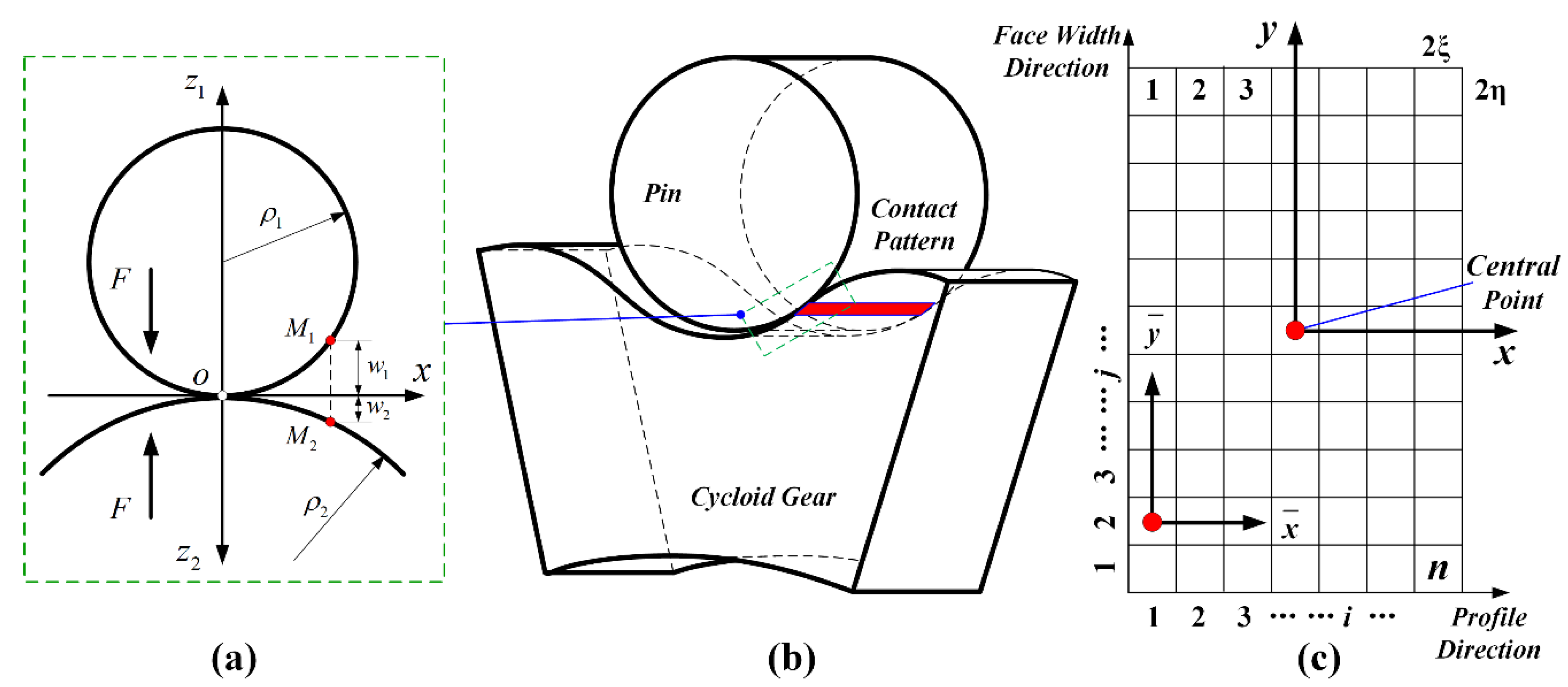
Figure 7 shows the contact state of a cycloid gear pair. The two coordinate systems
and
are defined with an identical origin at the initial contact point (region) from the side view, as shown in
Figure 7a. The tooth surface is defined in the
coordinate system where
and
represent the gear profile and width directions, respectively. The potential contact region is discretized into a contact grid, with each grid cell represented by a contact point, as shown in
Figure 7c. In the profile direction, the contact region of a tooth pair is divided into
grid cells of identical arc length. In the gear width direction, the same potential contact region is divided into
grid cells of equal length. The area of each contact grid cell is
.The contact deformation
at a point
can be represented as
where
and
are the Poisson’s ratio and Young’s modulus, and subscripts 1 and 2 refer to the roller and the cycloid gear, respectively.
is the distributed pressure in the contact area
.
The initial separations of the two surfaces are defined as
and
along the
z axis, respectively, which can be expressed as follows:
where
is the curvature radius of the roller, and
is the curvature radius of the cycloid gear teeth at the contact point [
5,
15].
For the case of FCM, according to Equation (5), the initial separations of the cycloid gear tooth surface can be rewritten as
Also, for the case of PCM, according to Equation (6), the initial separations of the cycloid gear tooth surface can be rewritten as
where
and
.
Similarly, for the case of LCM, according to Equation (7), the initial separations of the cycloid gear tooth surface can be rewritten as
Then, the governing integral equation for the three-dimensional elastic body contact of the cycloid gear pairs with a modified flexibility method can be expressed as
where
is the influence coefficient [
31], which can be represented as follows:
In addition to displacement requirements, two restrictions are placed on force. The normal force
between the contacting tooth pair is calculated by
where the pressure distributed in the contact region must be non-negative.
The above linear Equations (20) and (22) with the boundary condition can be solved simultaneously to obtain the contact region, contact deformation, and contact stress. Thus, the tooth compliance of the cycloid gear pairs can be represented as
Note that the tooth compliance is a nonlinear function of the forces, geometries, and material properties of the cycloid tooth pairs. The values of tooth compliance and the normal force can be calculated in an iterative process, which is described in the following section.
3.3. Loaded Tooth Contact Analysis
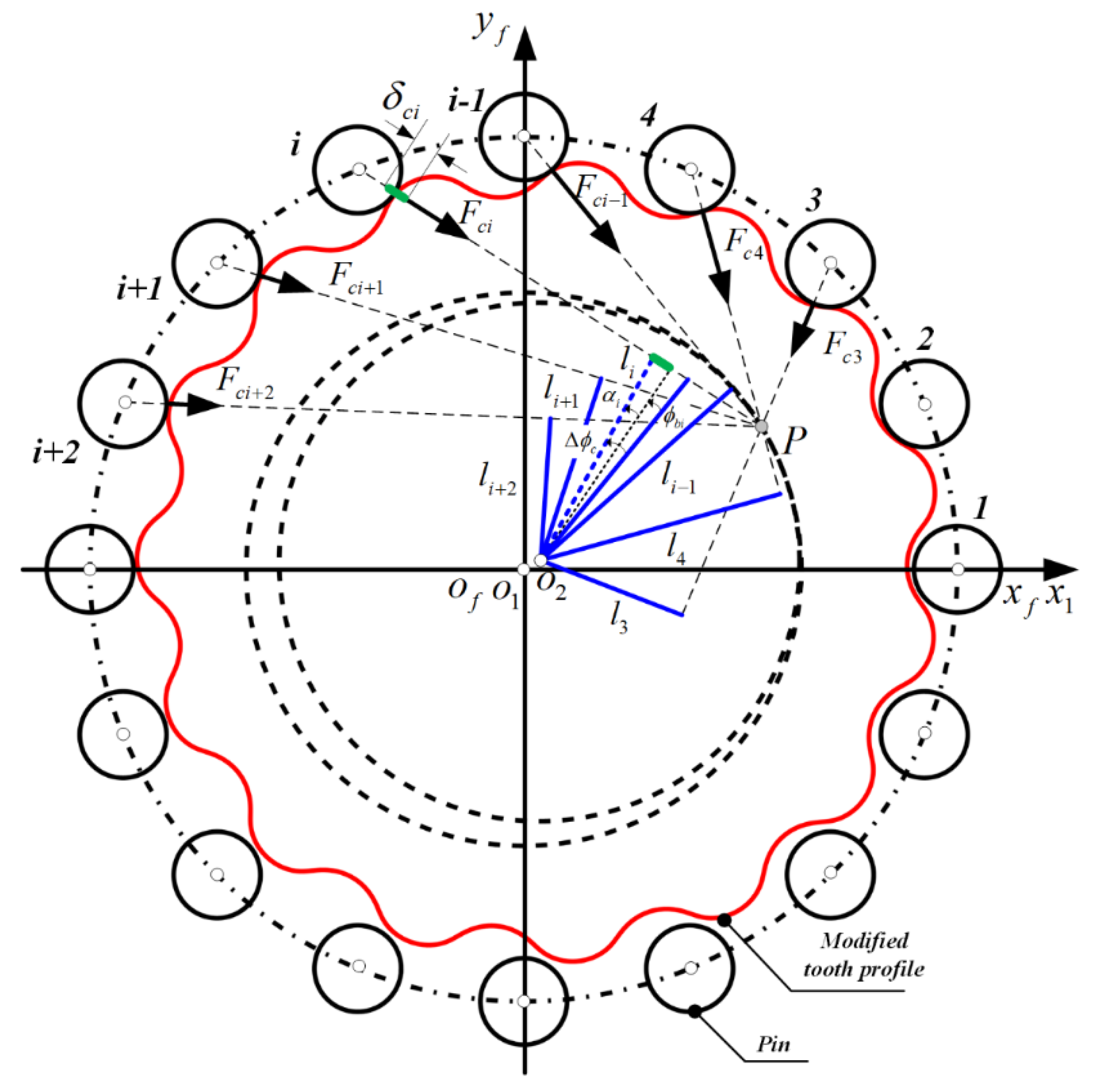
As shown in
Figure 8, the compatibility conditions should be satisfied to calculate the number of contacting tooth pairs, which can be represented as follows:
where
is the increment of the rotational angle of the cycloid disc, and
is a small angular displacement of the cycloid gear tooth.
Then, the force and moment static equilibrium equation can be expressed as
where the arm of force
can be represented geometrically as
An iterative process is repeated to find the solutions, as shown in
Figure 5. Firstly, two initial values of load and angular displacement are chosen to solve the compatibility and equilibrium Equations (24) and (25) and to calculate the tooth compliance according to Equations (15)–(23) in the meantime, after the backlash is calculated by unloaded TCA. All the values are updated each time the load and angular displacement enter into the system of equations. When the variations of the force and angular displacement converge within 1%, the iterative procedure is terminated to output the loads, contact stress, contact pattern, loaded transmission error (LTE), and gear ratio (GR).
5. Conclusions
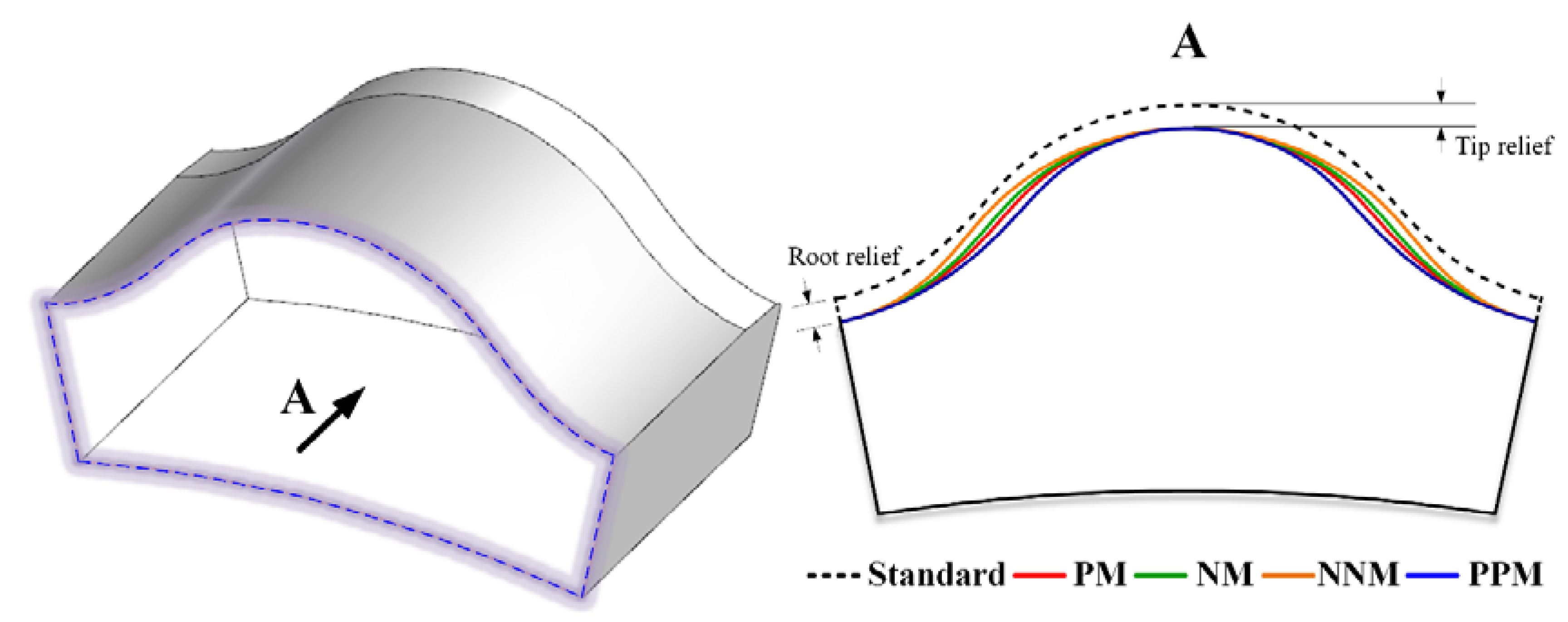
In this study, a semi-analytical load distribution model was proposed based on a three-dimensional and linear elastic solution. Different types of tooth profile and longitudinal modifications of cycloid gears were considered in this model to simulate and predict the multi-tooth contact conditions of cycloid drives. Numerical examples of load distribution analysis of cycloid drives using the proposed model were presented and compared to the current Hertz contact stiffness-based model to demonstrate the effectiveness of the predictions of this semi-analytical model. From the analysis results, the following specific observations and conclusions can be drawn:
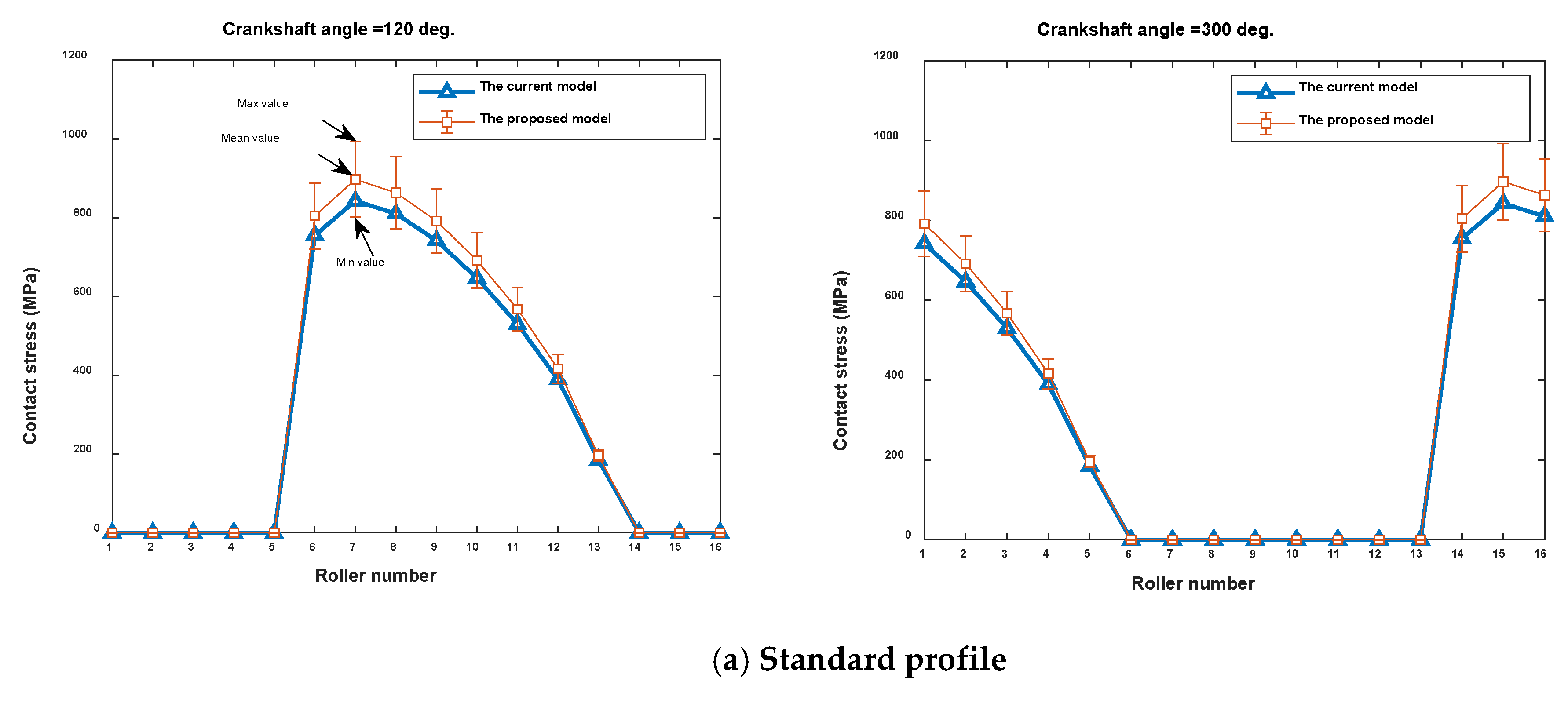
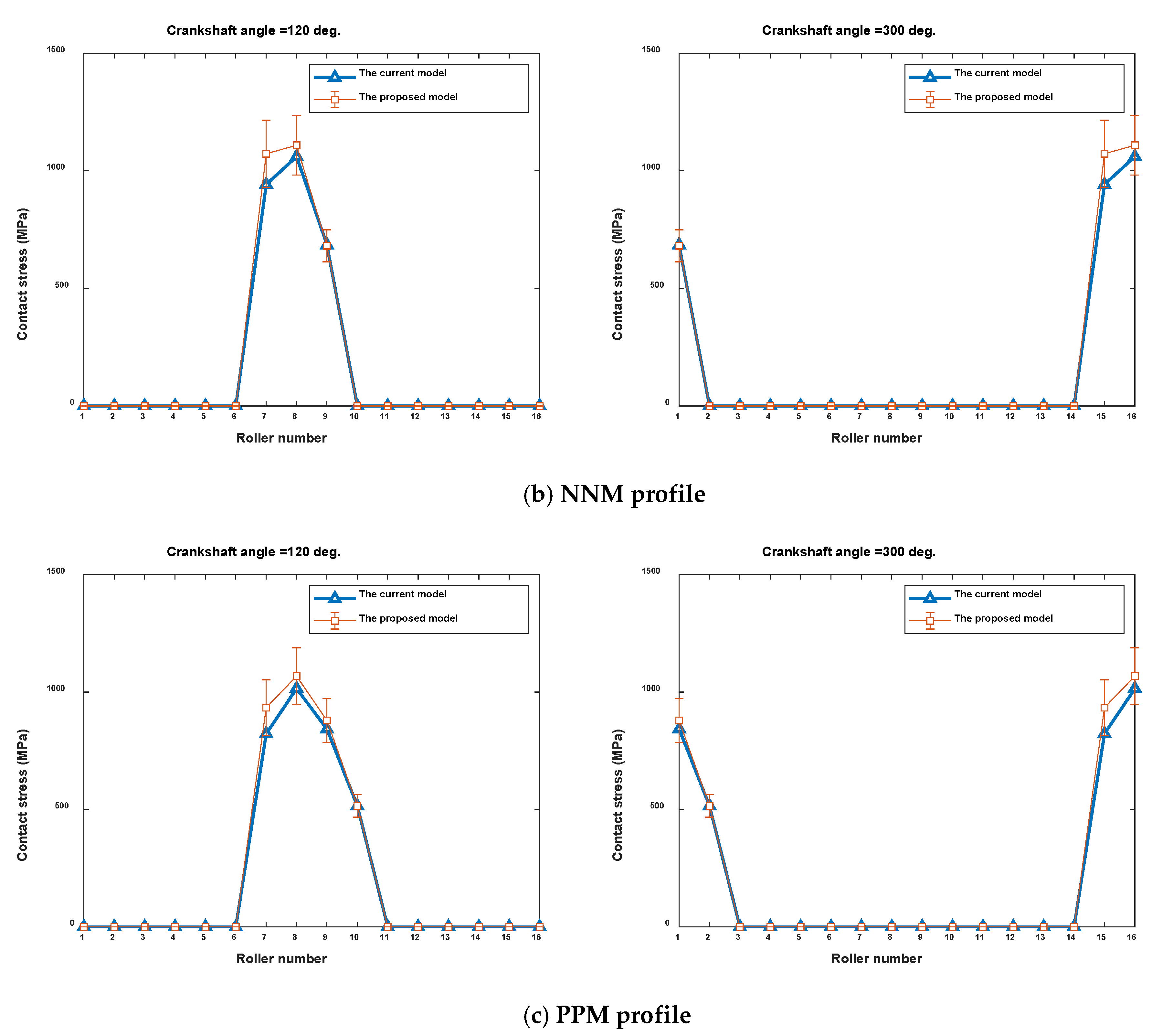
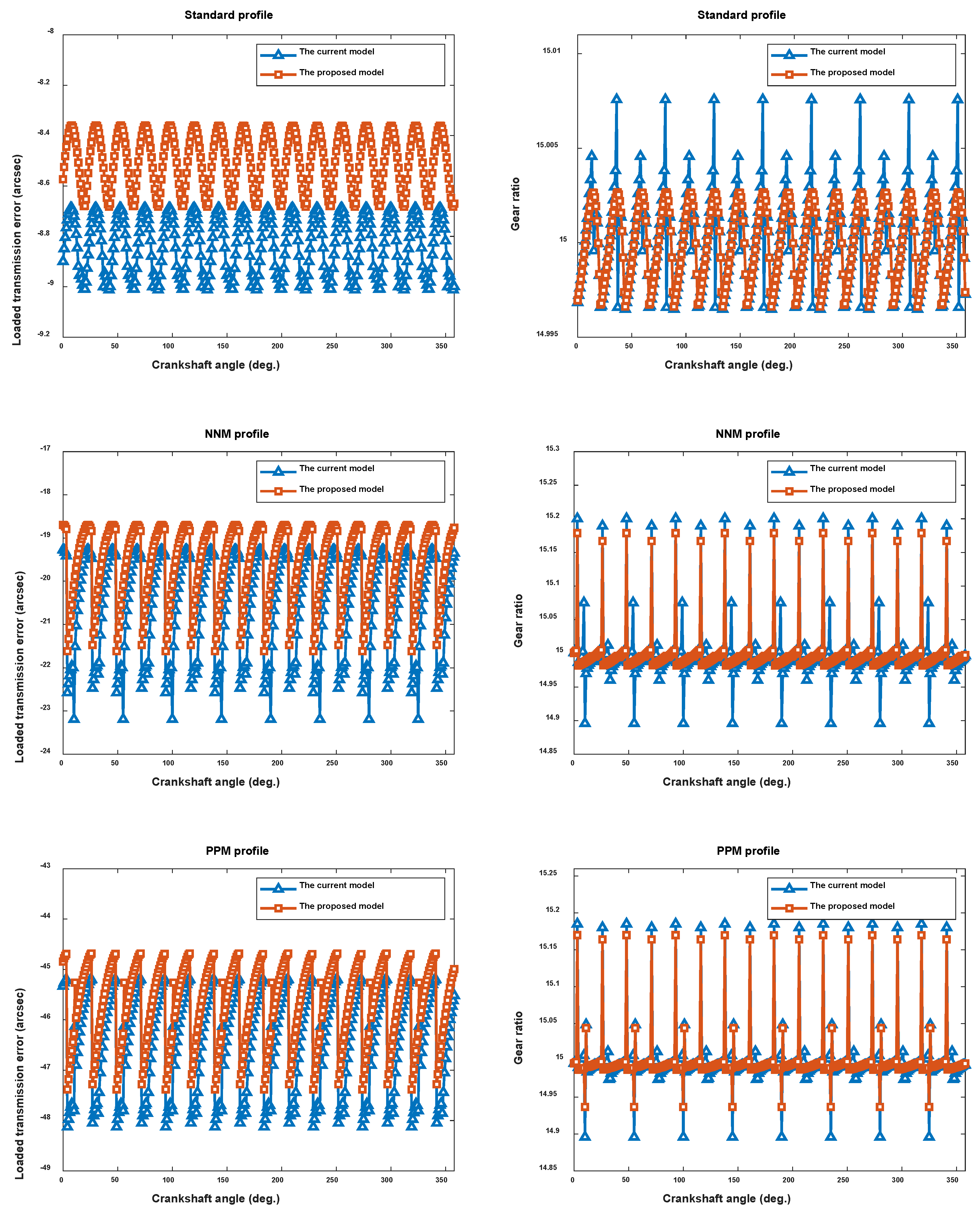
1. Load distribution, the number of tooth pairs in contact, and the loaded transmission error are influenced significantly by different types of tooth profile modification having the same radial clearance. NNM tends to yield smaller LTE than PPM, while the contact stress is quite the contrary. Both of them need to be optimized with proper modification parameters for the best performance of the cycloid drive.
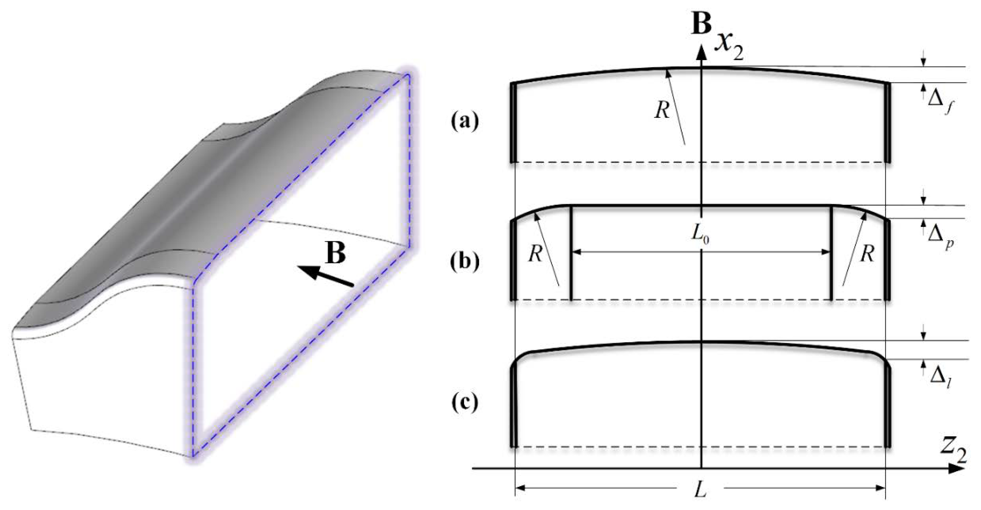
2. Tooth longitudinal modifications play a positive role in relieving the stress concentration at the two edges of cycloid gears and improving stress distribution along the axial direction, which should be considered seriously in the analysis and design of cycloid drives. Among the three proposed types of TLM, LCM exhibits better stress distribution characteristics, and further research is needed on the determination of modification parameters.
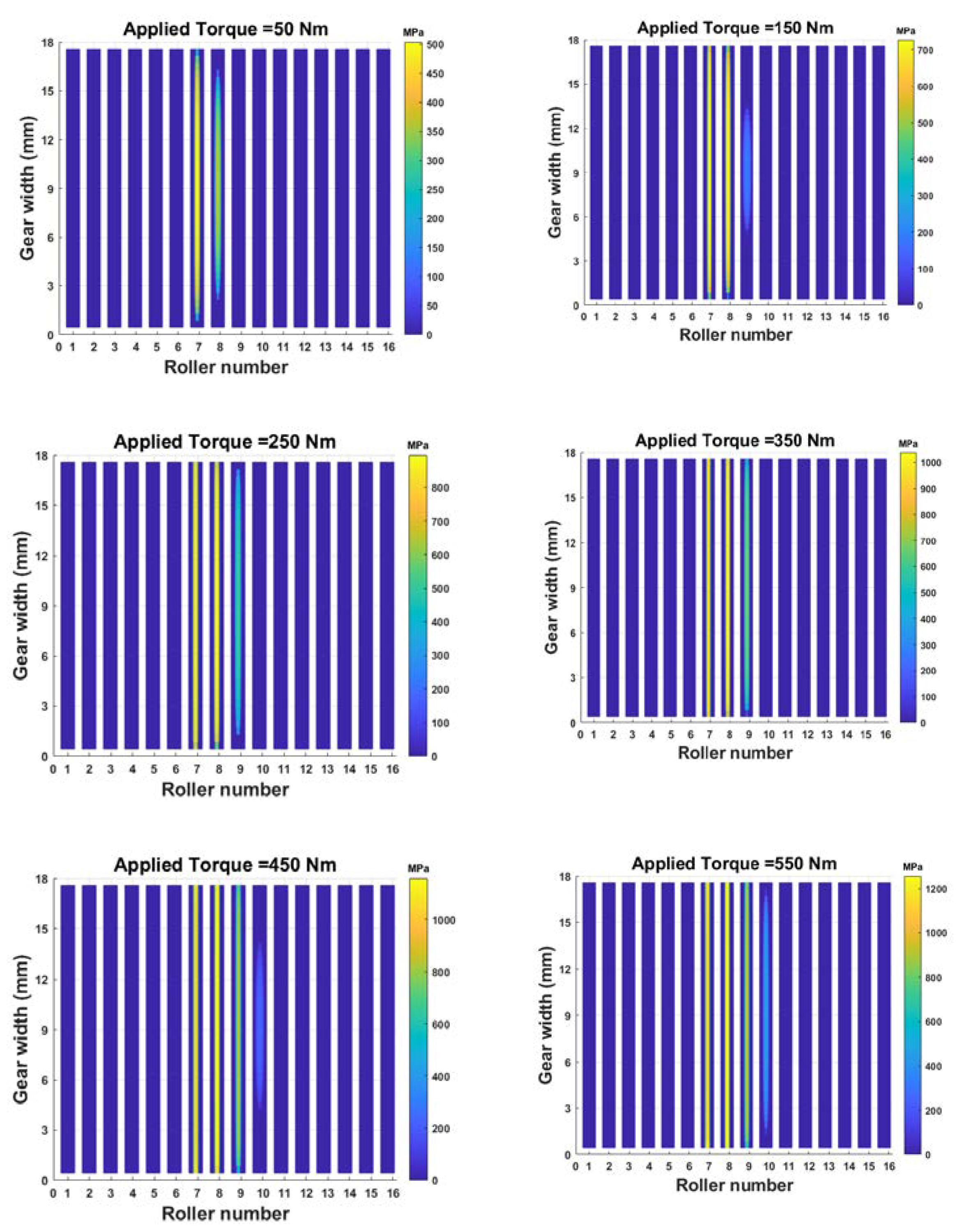
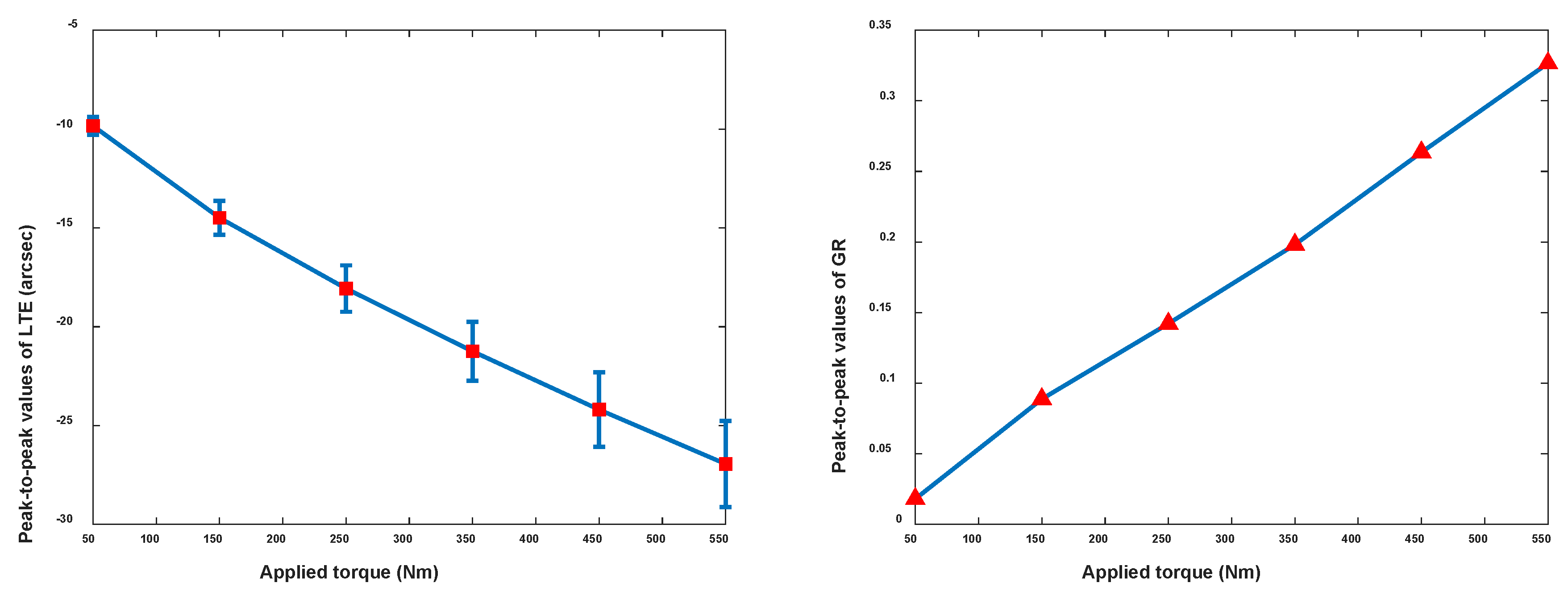
3. Applied torque levels were observed to have significant effects on the contact stress, LTE, and GR. The magnitudes of their maximum, peak-to-peak values change proportionally with torque. The contact pattern extends towards the edges of the tooth as the torque increases.
This proposed model can be applied to determine the limitation of the applied torque to prevent the contact stress exceeding the elastic limit of the gear material. Furthermore, due to the model’s better computational efficiency, it is very suitable for parameter sensitivity studies to optimize the design of cycloid drives. In the future, an experimental study will be carried out to validate the proposed model.


