Article

Development of Energy-Based Impact Formula—Part I: Penetration Depth

1
Department of Architectural Engineering, Kyonggi University, Suwon, Gyeonggi 16227, Korea
2
Department of Architecture and Architectural Engineering, Seoul National University, Seoul 08826, Korea
*
Author to whom correspondence should be addressed.
Appl. Sci. 2020, 10(14), 4964; https://doi.org/10.3390/app10144964
Submission received: 21 June 2020 / Revised: 16 July 2020 / Accepted: 17 July 2020 / Published: 19 July 2020

Abstract

:
Predicting the damage to a concrete panel under impact loading is difficult due to the complexity of the impact mechanism of concrete. Based on the experimental results obtained by various researchers, the energies involved in the impact mechanism are classified into seven categories: Kinetic energy, deformed energy of a projectile, elastic penetration resistance energy of the panel, overall deformed energy of the panel, spalling-resistant energy, tunneling-resistant energy, and scabbing-resistant energy. Using these impact mechanisms and the energy conservation law, a new energy-based penetration depth formula is proposed to predict the penetration depth. This is validated using 402 impact test results, which include those with high-strength concrete, ultra-high-performance concrete (UHPC), or steel fiber-reinforced concrete, those under very high-velocity impact, and those with a very low ratio of target panel thickness to projectile diameter. It is found that the new impact formula predicts the penetration depth quite well.

1. Introduction

Concrete is a primary material used in building structures and has contributed significantly to the development of the construction industry [1,2,3]. It became the main axis of the construction industry over a hundred years ago (before the beginning of the First World War), which led to an increased interest in protecting human life and the safety of building structures. There has also been a considerable interest in the impact resistance of concrete against conventional weapons. In the 1980s, the research on the blast and impact resistance of nuclear power plants was intensively carried out, and the research on the protection performance of structures against terrorism has been continued. To secure safety, blast and explosion design is important for preventing a building collapse and for minimizing local impact damage. Particularly, small fragments from explosions or conventional weapons (e.g., bullets and missiles) or car/airplane crashes can cause local damage, which also poses a safety threat. The local damage may cause the entire building to collapse, due to the lack of structural integrity, ductility, and irregularities that prevent the propagation of local damage [4].
There are several manuals or guidelines that recommend impact formulae for assessing local damage to reinforced concrete panels. The US Army recommends the Army Corps of Engineers (ACE) formula for evaluating the local damage to concrete panels in accordance with TM-5-855-1 [5], while the US Air Force recommends the modified National Defense Research Committee (NDRC) formula for evaluating the penetration depth in accordance with ESL-TR-87-57 (1987) [5]. The British Army recommends the UK Atomic Energy Authority (UKAEA) formula in accordance with the British Army Manual [5]. The ACE formula, the modified NDRC formula, and the UKAEA formula were developed in 1946, 1976, and 1990, respectively [5]. However, because these recommended formulae are old, they do not reflect the characteristics of the present concrete matrices.
Various materials have been developed to overcome the weakness of concrete. Concrete exceeding 100 MPa is widely used in the construction industry. Various fibers have been added to increase the ductility and energy dissipation capacity of the concrete, and blast furnace slag was added to improve the fluidity and strength. Concrete with various properties has been produced by varying the concrete mixture and methods [6]. In particular, new concrete matrices exhibit improved tensile strength due to the presence/addition of steel fibers. For most high-strength concrete, steel fibers are used, which greatly improve the concrete’s tensile characteristics. There are few impact formulae that can be applied to high-strength concrete, and there is no impact formula that reflects this increased tensile strength due to steel fibers, except for the Hughes formula. Therefore, it is necessary to develop a new impact formula that can be applied to high-strength concrete and reflects its increased tensile strength due to steel fibers.
In addition, the existing impact formulae are inaccurate when the ratio of a projectile’s diameter to a panel’s thickness is low. For these reasons, it is necessary to develop a new impact formula that is highly accurate even in cases involving a low projectile diameter-to-panel thickness ratio. However, most of the models have been derived from experiments that used a limited number of variables. The force–penetration depth relationship was commonly used. In addition, there were some errors in the predicted values assigned to different experimental results.
Therefore, a new theoretical model, rather than that based on the experimental results, and a theoretical framework are required to develop a new impact formula. This paper proposes a new impact formula based on the theoretical framework proposed by Hwang et al. [7], and the study on the impact mechanism, impact force, strain rate, and coefficient related to the penetration is extended. The proposed model is derived from the energy conservation law and the new impact mechanism. This model presented in the paper is verified based on the experimental data.

2. Literature Review

Prior to 1943, the Ordnance Department of the US Army and the Ballistic Research Laboratory (BRL) conducted multiple impact tests on concrete structures [5]. Based on their experimental data, the Army Corps of Engineers [8] developed the penetration formula (Equation (1)), where the term Mp/dp3 indicates the missile caliber density. It was based on the regression analyses made on the experimental data for 37, 75, 76.2, and 155 mm steel cylindrical missiles.
x p e d p = 3.5 × 10 4 f c ( M p d p 3 ) d p 0.215 V i m p 1.5 + 0.5
where xpe is the penetration depth (m); Mp is the mass of a projectile (kg); dp is the diameter of a projectile (m); Vimp is the impact velocity of a projectile (m/s); and f’c is the compressive strength of concrete (Pa).
In 1946, the National Defense Research Committee (NDRC) carried out further experiments based on the ACE formula and developed the NDRC formula [9]. This formula assumes that a rigid missile impacts massive concrete targets, and includes the following characteristics: The impact function, G-function; the nose shape factor (Np) according to a projectile’s shape; and the introduction of the concrete penetrability factor (K). The G-function was proposed, which considered the scale effect, caliber density, and shape and velocity of the bullet [9]. The Np for the NDRC formula had values of 0.72, 0.84, 1.0, and 1.14 for flat, hemispherical, blunt, and very sharp noses, respectively. The NDRC formula defines K, which is similar to that of the Petry formula, Kp. However, after 1946, there was less interest in the impact resistance of concrete, and no further studies were conducted on K. Kennedy [10] conducted additional research on K, and K was defined as 180/(f’c0.5) for the relation between concrete compressive strength and concrete penetrability. The modified NDRC formula (Equations (2) and (3)) was proposed with the new K value. For now, the NDRC formula can be recognized as the modified NDRC formula.
G = 3.8 × 10 5 N p M p d p f c ( V i m p d p ) 1.8
G = ( x p e 2 d p ) 2   for   x p e d p 2   or   G = x p e d p 1   for   x p e d p > 2
where G is the impact function; xpe is the penetration depth (m); Np is the nose shape factor (0.72, 0.84, 1.0, and 1.14 for flat, hemispherical, blunt, and very sharp noses, respectively); Mp is the mass of a projectile (kg); dp is the diameter of a projectile (m); Vimp is the impact velocity of a projectile (m/s); and f’c is the compressive strength of concrete (Pa).
Haldar’s group studied the safety of nuclear power plants with respect to missiles [11,12], focusing on the local impact damages to the concrete with respect to turbine missiles. Haldar and Miller [12] proposed penetration equations using the impact factor (I), which comprises Mp, Np, Vimp, dp, and f’c (Equation (4)). Haldar and Hamieh [12] modified the suggested penetration depth and formulae (Equations (5) to (7)) after further analyzing the additional experimental data obtained using small projectiles, such as bullets. The penetration depth (xpe) could be predicted for all missile types, from bullets to turbines. In the formula, the value of Np is taken from the modified NDRC formula (Equation (2)) [9].
I = M p N p V i m p 2 d p 3 f c
x p e d p = 0.0308 + 0.2251 I   for   0 . 3 I 4.0
x p e d p = + 0.6740 + 0.0567 I   for   4.0 < I 21.0
x p e d p = 1.1875 + 0.0299 I   for   21.0 < I 455
where xpe is the penetration depth (m); Np is the nose shape factor (0.72, 0.84, 1.0, and 1.14 for flat, hemispherical, blunt, and very sharp noses, respectively); Mp is the mass of a projectile (kg); dp is the diameter of a projectile (m); Vimp is the impact velocity of a projectile (m/s); and f’c is the compressive strength of concrete (Pa).
Hughes [13] proposed an impact formula using the force–penetration model. This formula considers the strain rate effect on concrete tensile strength (ft) using the dynamic increase factor (SHughes, Equation (8)), which is defined by introducing an impact factor (I, Equations (9) and (10)) that is similar to that used by Haldar and Hamieh [12]. The dimensionless impact factor (I) represents the concrete penetrability and comprises Mp, Vimp, dp, and fr. While other formulae use concrete compressive strength (f’c), this formula is characterized by the use of the tensile strength of concrete (f t). The values of Np were set as 1, 1.12, 1.26, and 1.39 for flat, blunt, spherical, and very sharp noses, respectively. The penetration depth formula was derived from I, SHughes, and Np, as shown in Equation (11), and is applicable only when I is smaller than 3500.
S H u g h e s = 1 + 12.3 ln ( 1 + 0.03 I )
I = M p V i m p 2 f t d p 3
f t = 0.63 f c
x p e d p = 0.19 N p I S H u g h e s ;   I < 3500
where xpe is the penetration depth (m); ft is the tensile strength of rupture (Pa); Mp is the mass of a projectile (kg); dp is the diameter of a projectile (m); Vimp is the impact velocity of a projectile (m/s); Np is the nose shape factor (1, 1.12, 1.26, and 1.39 for flat, blunt, spherical, and very sharp noses, respectively); and f’c is the compressive strength of concrete (Pa).
Barr [14] contributed to the compilation of the report created by the UK Atomic Energy Authority (UKAEA), Central Electrical Generating Board (CEGB), and National Nuclear Corporation, which proposed the penetration depth formula based on the modified NDRC formula. The G-function is the same as the modified NDRC formula (Equation (2)), and the ratio of xpe to dp is further subdivided as shown in Equations (12) to (14), because the nuclear power plant has a relation with low-velocity projectiles or fragments [5]. The range of parameters for the penetration depth is 25 < Vimp < 300 m/s and 22 < f’c < 44 MPa, but that for the scabbing limit thickness is 29 < Vimp < 238 m/s and 26 < f’c < 44 MPa.
x p e d p = 0.275 ( 0.0756 G ) 0.5   for   G 0.0726
x p e d p = ( 4 G 0.242 ) 0.5   for   0.0726 G 1.0605
x p e d p = G + 0.9395   for   1 . 0605 G
where xpe is the penetration depth (m); G is the impact function in the modified NDRC formula (Equation (2)); dp is the diameter of a projectile (m); Vimp is the impact velocity of a projectile (m/s); and f’c is the compressive strength of concrete (Pa).
In 1985, the UK Nuclear Electric (NE) launched a part of the General Nuclear Safety Research (GNSR) program to examine the impact behavior of reinforced concrete structures [5,15,16]. The experiment was performed in the Structural Test Center (STC at Cheddar), Rogerstone Power Station, Horizontal Impact Facility (HIF), and Winfrith Technology Center (WTC). The University of Manchester, Institute of Science and Technology (UMIST) formula (2001) [5] was suggested regarding the critical kinetic energies of missiles, and the penetration depth formula is represented in Equations (15) and (16). This formula is verified for 0.05 < dp < 0.6 m, 35 < Mp < 2500 kg, xpe/dp < 2.5, and 3 < Vimp < 66.2 m/s. The nose shape factor is 0.72 for a flat nose, 0.84 for a hemispherical nose, 1.0 for a blunt nose, and 1.13 for a sharp nose.
x p e d p = ( 2 π ) N p 0.72 M p V i m p 2 σ t d p 3
σ t = 4.2 f c + 135 × 10 6 + [ 0.014 f c + 0.45 × 10 6 ] V i m p
where xpe is the penetration depth (m); Np is the nose shape factor; Mp is the mass of a projectile (kg); dp is the diameter of a projectile (m); Vimp is the impact velocity of a projectile (m/s); σt is the rate-dependent strength of concrete (Pa); and f’c is the compressive strength of concrete (Pa).
Forrestal’s research group studied the dynamic cavity expansion model of materials, which has been applied to various materials, such as soil, concrete, and rock [17]. The dynamic cavity expansion model was originally proposed by Bishop et al. [18,19]. Hopkins [20] studied dynamic-cavity expansion for incompressible materials, and Forrestal and Luk [21] developed and expanded the model to include compressible materials.
Luk and Forrestal’s [22] paper for the dynamic-cavity expansion model was submitted ahead of that for the penetration formula, but published later than the paper proposed for the penetration model for concrete using the dynamic cavity expansion model, as well as a spherical and ogival nose projectile. The force of a projectile’s tip was obtained through a subsequent study [23]. The shear stress under triaxial conditions is key to calculating using this formula, and studies on the triaxial shear stress of concrete are lacking. Later, Forrestal et al. [24] developed a semi-analytical penetration formula and calibrated the factors based on six impact experimental datasets for the ogive nose projectile. Li and Chen [25] developed the penetration depth formula and suggested a new value for KLi (Equations (17) to (24)). Li’s research group also studied the nose shape factor and applied the results to penetration depth prediction, as shown in Figure 1 and Equations (22) to (24) [25,26]. The term Mp/ρpdp3 indicates the ratio between the missile section pressure and the target’s areal density, for considering a long projectile. This formula is applicable for xpe/dp over 0.5 [5]. If the value of xpe/dp is less than 0.5, the penetration depth can be obtained from Equation (25).
x p e d p = ( 1 + k π / 4 N c b ) ( 1 + I / N c b ) 4 k π I   for   x p e d p k
x p e d p = 2 π N c b ln [ 1 + I / N c b 1 + k π / 4 N c b ] + k   for   x p e d p > k
k = 2   for   x p e d p 5 ,   k = ( 0.707 + l n o s e d p )   for   x p e d p 5
I = 1 K L i ( M p V i m p 2 d p 3 f c )   and   K L i = 72 ( f c ) 0.5
N c b = 1 N p ( M p ρ c d p 3 )
N p = 1 3 ( R n o s e / d p ) 1 24 ( R n o s e / d p ) 2   for   an   ogival   nose
N p = 1 1 + 4 ( l n o s e / d p ) 2   for   a   conical   nose
N p = 1 1 8 ( R n o s e / d p )   for   a   blunt / spherical   nose
x p e d p = 1.628 ( 1 + k π / 4 N c b 1 + I / N 4 k π I ) 1.395   for   x p e d p 0 . 5
where xpe is the penetration depth (m); Np is the nose shape factor; Mp is the mass of a projectile (kg); dp is the diameter of a projectile (m); Vimp is the impact velocity of a projectile (m/s); f’c is the compressive strength of concrete (Pa); h is the panel thickness (m); Rnose and lnose are the radius and length of a projectile nose, respectively (Figure 1); ρc is the density of concrete (kg/m3); KLi is the concrete penetrability-resistant function of the Li–Chen formula; and k is the reference value related to the panel thickness and the diameter of a projectile.

3. Development of New Energy-Based Penetration Formula

Concrete itself is a composite material, for which the impact mechanism is not clearly defined; thus, it is not easy to predict the damage to a concrete panel. In many cases, the equation is derived from the relation between kinetic energy and force–penetration depth, and is corrected by the experimental data. Unlike the conventional impact model development method, this paper develops a new impact formula based on both the theoretical background and the energy conservation law. Energy consumption occurs in each impact mechanism step and the total energy consumed by a concrete panel must be the same as the external energy. Therefore, the impact mechanism is newly defined in this paper, which describes the consumed quantity based on the energy conservation law between the external energy carried by the projectile and the energy consumption in the impact mechanism. In the following sections, the overall concept of the new impact formula is introduced and the material properties affected by the strain rate effect in the impact mechanism are defined. The value of the energy consumption of each step of the impact mechanism is derived in logical order. Finally, a new impact formula for evaluating the damage to a (reinforced) concrete panel under a high-velocity impact load is presented.

3.1. Concept of New Formula

3.1.1. Impact Mechanism and Energy Conservation

Hwang et al. [7] defined the impact mechanism and derived the consumed energies. In this paper, the impact mechanism, regardless of the panel’s thickness, is redefined, and each consumed energy is newly derived, by referring to Hwang et al. [7]. The energies involved in the impact mechanism can be divided into five types, and two additional types in the case of special conditions, as shown in Figure 2. The first is the kinetic energy of a projectile (EK), considered as external energy, which is an essential critical energy for concrete failure. The second is the deformed energy of a projectile (EDP) at the moment of contact. The third is the elastic deformed energy of a concrete panel (EEP). The fourth is the overall deformed energy of a concrete panel (ESD). The fifth is the spalling-resistant energy (ESP), which determines the type of failure mode. This energy is the energy generated by the concrete drag force around the collision point. One of the additional types of energy is the tunneling-resistant energy (ET), which occurs when a flying projectile has energy over the spalling-resistant energy. The other type includes the scabbing-resistant energy (ESC), which occurs when the panel thickness is insufficient for absorbing ESP. In this case, all the kinetic energy, except for EDP, is transferred to the concrete panel. However, if the concrete panel’s thickness is insufficient to absorb the collision energy, it is reflected from the opposite face and can cause scabbing failure. Conversely, if a panel is thick, the scabbing-resistant energy (reflected energy on the rear face of the concrete panel) is weak or does not occur. Thus, ESC can occur under certain conditions, and is not included in the energy conservation law between the kinetic energy of a projectile and consumed energies defined as Figure 2a–e.

3.1.2. Forces Acting in Impact Mechanism

Considering the experimental results and the existing theoretical models, it can be assumed that the penetration depth is affected by compressive strength, while the scabbing depth is affected by tensile strength. In addition, the slope of the spalled and scabbed cones is in the form of shear failure. Therefore, it is shown that spalling failure is shear failure affected by compressive strength (Figure 3), while scabbing failure is shear failure affected by tensile strength (Figure 4). In addition, it is assumed that shear and compressive stresses act on the interface between a spalled concrete cone and a reinforced concrete panel (Figure 3). Shear and tension stresses act on the interface between a scabbed concrete cone and a panel (Figure 4). Based on the punching slab research [27,28,29,30], the shear stress capacities controlled by compression or tension are defined as Equations (26) to (29), respectively. Here, vnc,st(z) indicates the shear stress capacity controlled by compression under static loading, while vnt,st(z) indicates that controlled by tension under static loading. As shear strength is defined under static loading, dynamic material properties should be applied considering dynamic conditions (Equations (30) to (33)).
v n c , s t ( z ) = f c , s t ( f c , s t σ u , s t ( z ) )   ( MPa ,   mm )
v n c , s t ( z ) = f t , s t ( f t , s t + σ u , s t ( z ) )   ( MPa ,   mm )
σ u , s t ( z ) = f c , s t [ 2 ( α z c u ) ( α z c u ) 2 ]   ( MPa ,   mm )
f t , s t = f t , s t ( 1 σ u , s t ( z ) / f c , s t )   ( MPa )
v n c , d y n ( z ) = f c , d y n ( f c , d y n σ u , d y n ( z ) )   ( MPa ,   mm )
v n c , d y n ( z ) = f t , d y n ( f t , d y n + σ u , d y n ( z ) )   ( MPa ,   mm )
σ u , d y n ( z ) = f c , d y n [ 2 ( α z c u ) ( α z c u ) 2 ]   ( MPa ,   mm )
f t , d y n = f t , d y n ( 1 σ u , d y n ( z ) / f c , d y n )   ( MPa )
where vnc,st(z) and vnc,dyn(z) are the static shear stress capacity (MPa) controlled by static compression and the dynamic shear stress capacity (MPa) controlled by dynamic compression, respectively; vnt,st(z) and vnt,dyn(z) are the static shear stress capacity (MPa) controlled by the static tension and the dynamic shear stress capacity (MPa) controlled by the dynamic tension, respectively; z is the distance from the neutral axis (mm); f’c,st and f’c,dyn are the static compressive stress of concrete and the dynamic compressive stress of concrete (MPa), respectively; ft,st and ft,dyn are the static tensile stress of concrete and the dynamic tensile stress of concrete (MPa), respectively; σu,st and σu,dyn are the static compressive stress (MPa) and the dynamic compressive stress affected by strain rate, respectively; σu,st and σu,dyn are related to the distance z using the parabolic stress–strain relationship of concrete; α is the ratio of the current compressive strain αεο to the strain εο related to the uniaxial concrete compressive strength; αεο is the current compressive strain at the extreme compression fiber of the cross-section; and cu is the depth of the concrete compression zone (mm). The f’t,st and f’t,dyn are the effective static tensile strength reduced by the transverse compressive stress (MPa) [31] and the effective dynamic tensile strength reduced by the transverse compressive stress (MPa), respectively. If there is no measured value of the static tensile strength of concrete, then the value of ft,st can be obtained from the relation between the compressive and tensile strength of concrete (Equations (34) and (35)) according to the fib Model Code 2010 [32].
f t , s t = 0.3 ( f c , s t ) 2 / 3   for   f c , s t < 50   MPa
f t , s t = 2.12 ln [ 1 + 0.1 ( f c , s t + 8 ) ]   for   f c , s t 50   MPa
where ft,st is the static tensile strength of concrete (MPa) and f’c,st is the static compressive strength of concrete (MPa).
The stresses acting on the interface between the spalled concrete cone and the concrete panel under impact loading are demonstrated in Figure 3. It is assumed that the amount of deformation of the concrete panel is not large and does not significantly influence the penetration depth [7]. Therefore, the curvature of the concrete panel is assumed to be at stage B, which is the point where the concrete crack starts. Here, εcr is the concrete strain at cracking, whose value can be assumed to be the strain at 30% of the uniaxial compressive strength [33]. Assuming that the relation between the stress and strain is linear, the value of α is 0.2 (Equation (36)). The value of cu and z is assumed to be equal to 0.5h in the case of an unreinforced and reinforced concrete panel (Equations (37) to (39)). Therefore, vnc,st(z) and vnt,st(z) can be reduced to Equations (40) and (41), respectively. Considering dynamic loading, Equations (40) and (41) are changed to Equations (42) and (43), respectively.
α = ε c r ε o = ε p e a k × 30 % ε o = 0.002 × 30 % 0.002 = 0.3
σ u , s t ( z ) = f c , s t [ 2 ( 0.3 × 0.5 h 0.5 h ) ( 0.3 × 0.5 h 0.5 h ) 2 ]
σ u , s t ( z ) = 0.51 f c , s t
f t , s t = 0.49 f t , s t
v n c , s t ( z ) = 0.7 f c , d y n
v n t , s t ( z ) = 0.24 ( f t , s t ) 2 + 0.25 f t , s t f c , s t
v n c , d y n ( z ) = 0.7 f c , d y n
v n t , d y n ( z ) = 0.24 ( f t , d y n ) 2 + 0.25 f t , d y n f c , d y n
where εpeak is the strain at the ultimate compressive strength of concrete, which is normally 0.002; and εο is the compressive strain corresponding to the compressive concrete strength, which is 0.002 in ACI 318-19 [34].
Steel fibers can increase concrete tensile strength and reduce its scabbing failure. This should reflect the effect of steel fibers, which play a role in increasing the tensile strength of concrete. Musmar [35] proposed Equation (44) to describe the tensile strength of concrete reinforced with steel fibers under static loading, which can be converted to Equation (45) for considering dynamic loading. The obtained values can be applied to Equation (43).
f t s , s t = f t , s t ( 1 + 2 3 l f d f V f )
f t s , d y n = f t , d y n ( 1 + 2 3 l f d f V f )
where fts,st and fts,dyn are the static tensile stress of steel fiber-reinforced concrete (MPa) and the dynamic tensile stress of steel fiber-reinforced concrete affected by strain rate, respectively; lf is the steel fiber length (mm); df is the steel fiber diameter (mm); and Vf is the steel fiber volume fraction (%).

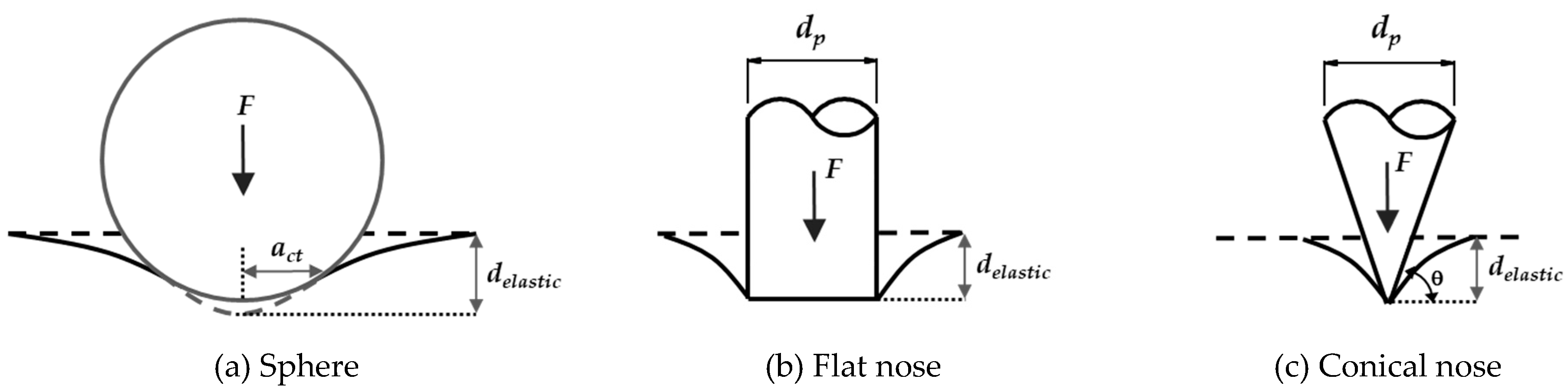
3.1.3. Force on the Nose of a Projectile

To calculate the elastic deformation of a panel, a projectile, and a strain rate, Forrestal’s study for normal stress on the nose of a projectile is referred [19,24,25,36]. The force (Fnose) is represented as shown in Equations (46) to (51).
F n o s e = π r p 2 ( τ o , s t A + N p B ρ c V i m p 2 )
A = 2 3 2 ( τ m , s t τ 0 , s t ) ln [ γ 1 + τ 0 , s t / 2 E c , s t ]
B = 2 2 ( 1 η * ) + [ 3 τ 0 , s t / E c , s t + η * ( 1 3 τ 0 , s t / 2 E c , s t ) 2 ] γ 2 γ 2 ( 1 + τ 0 , s t / 2 E c , s t ) 4 [ 1 + 3 ( 1 + τ 0 , s t / 2 E c , s t ) 3 ( 1 η * ) ]
γ = [ ( 1 + τ 0 , s t 2 E c , s t ) 3 ( 1 η * ) ] 1 / 3
η * = 1 ρ 0 / ρ *
N p = 8 C R H 1 24 C R H 2
where rp is the radius of a projectile (mm), τ0,st is the static shear stress without uniaxial load (MPa); τm,st is the static shear stress under triaxial loads (MPa); Np is the nose shape factor of a projectile; ρc is the density of concrete (kg/m3); Vimp is the impact velocity (m/s); Ec,st is the elastic modulus of concrete under the static loading (MPa); η∗ is the function related to the density of concrete; and CRH is the caliber-radius-head.
η∗ can be transferred to another form using the bulk modulus and the relation between the change in volume and other physical quantities. When inducing dynamic loading on an object, the body exhibits high hydrostatic pressures on short timescales [37]. Assuming that equal forces (Fcube) act on all surfaces, the original volume (Volori) can be changed to the deformed volume (Voldef). The reduced volume (ΔVol) is defined as the original volume minus the deformed volume (Equation (52)). It is related to the bulk modulus (K), force, area, and original volume, and η∗ is newly derived from Equations (52) to (57).
Δ V o l = V o l o r i V o l d e f = 1 K F c u b e A c u b e V o l o r i
V o l d e f = V o l o r i 1 K F c u b e A c u b e V o l o r i = V o l o r i ( 1 1 K F c u b e A c u b e )
K = E c , s t 3 ( 1 2 v c , s t )
V o l d e f = V o l o r i ( 1 3 ( 1 2 ν ) E c , s t F c u b e A c u b e ) = V o l o r i ( 1 3 ( 1 2 ν ) E c , s t σ c , s t )
η * = 1 ρ 0 / ρ * = 1 weight / original   volume weight / deformed   volume = 1 V o l d e f V o l o r i
η * = 1 V o l d e f V o l o r i = 1 V o l o r i ( 1 3 ( 1 2 ν c , s t ) E c , s t σ ) V o l o r i = 3 ( 1 2 ν c , s t ) E c , s t σ c , s t
where Δ V o l is the volume obtained by subtracting the changed volume from the original volume (mm3); Volori is the volume of the original cube (mm3); Voldef is the changed volume of the cube under triaxial loads (mm3); K is the bulk modulus (MPa); Fcube is the acting force on the surface of the cube (N); Acube is the area of the one cube’s face (mm2); vc,st is Poisson’s ratio of the concrete under the static loading; σc,st is the compressive strength of the concrete under the static loading (MPa); and Ec,st is the elastic modulus of the concrete under the static loading (MPa).
Using the newly derived η∗, the expressions of γ and A can be changed to Equations (58) and (59), respectively.
γ = V c = [ ( 1 + τ 0 , s t 2 E c , s t ) 3 ( 1 3 ( 1 2 ν c , s t ) E c , s t σ c , s t ) ] 1 / 3
A = 2 3 2 ( τ m , s t τ 0 , s t ) ln [ [ ( 1 + τ 0 , s t 2 E c , s t ) 3 ( E c , s t 3 ( 1 2 ν ) σ E c , s t ) ] 1 / 3 ( 1 + τ 0 , s t / 2 E c , s t ) ]
where τ0,st is 0.33λ(f’c,st)0.5 and τm,st can be considered as vnc(z) because both τm,st and vnc(z) are affected by compressive stress. Therefore, the ratio of τm,st to τ0,st is 2.12(f’c,st)0.5 when using normal-weight concrete (Equations (60) to (62)). Given that concrete is normal-weight, A can be reduced as shown in Equation (63).
A = 2 3 2 ( 2.12 f c , s t ) ln [ [ ( 1 + ( 0.33 f c , s t ) 2 E c , s t ) 3 ( E c , s t 3 ( 1 2 ν ) f c , s t E c , s t ) ] 1 / 3 ( 1 + ( 0.33 f c , s t ) 2 E c , s t ) ]
E c , s t = w c 1.5 0.043 f c , s t
E c , s t = 4700 f c , s t for   normal   weight   concrete
A = 2 3 2 ( 2.12 f c , s t ) ln [ 0.073 ( f c , s t + 0.275 ) 1 / 3 ]
The value of B has a narrow range and is suggested to be 1.0 for concrete [24,25]. In this paper, the value of B is also set as 1.0. Finally, the force on the nose of the projectile is expressed as Equations (64) to (66).
F n o s e = π r p 2 ( τ o , s t A + N p ρ c V i m p 2 )
A = 2 3 2 ( 2.12 f c , s t ) ln [ 0.073 ( f c , s t + 0.275 ) 1 / 3 ]
N = 8 C R H 1 24 C R H 2
where Fnose is the normal force on the nose of a projectile (N); rp is the radius of a projectile (mm); τ0,st is the static shear stress without uniaxial load (MPa); Np is the nose shape factor of a projectile; ρc is the density of concrete (kg/m3); Vimp is the impact velocity (m/s); f’c,st is the compressive strength of concrete under the static loading (MPa); and CRH is the caliber-radius-head (Rnose/dp).

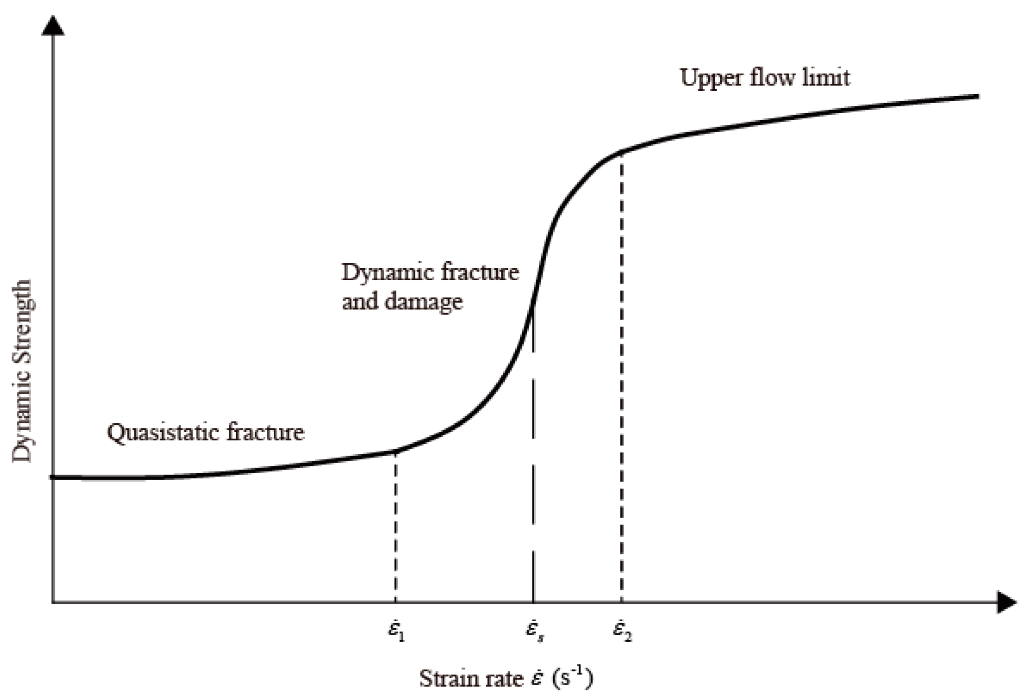
3.1.4. Properties of Materials Affected by Strain Rate

In this impact study, the material properties are related to the strain rate under the huge short-term load (Figure 5). The material under dynamic loading exhibits properties different from those exhibited under quasi-static loading, and the yielding stress and elastic modulus of the material increase with the strain rate [38,39]. As the material strength increases rapidly at the high strain rate, it is essential to study and consider the strain-rate effect in impact load studies. In particular, the strain rate is closely related to the velocity of a projectile, and is very sensitive and difficult to predict. As it is difficult to study these matters separately, the strain rate value is referenced from Ramesh [40], and the properties of materials affected by the strain rate are referenced from the fib Model Code 2010 [32].
Strain rate is an important factor for evaluating the impact resistance and is dependent on the material properties of the projectile and the target. For a general estimate of the dynamic properties of materials, the Split-Hopkinson Pressure Bar (SHPB) and Kolsky Bar are used, which exhibit a difference. The SHPB indicates the performance of compression experiments, whereas the Kolsky Bar covers various properties such as compression, tension, and torsion [40]. Thus, this study refers to the Kolsky Bar. When imposing impact loading on the input bar, an incident pulse (εΙ) is generated, after which that bar transfers the incident pulse at its one end to the specimen connected to the other end. The incident pulse first reaches the test specimen, after which it is separated into a reflected pulse (εR) and a transmitted pulse (εΤ), as shown in Figure 6. The particle velocity (v1) at interface 1 is defined as Equation (67) and that at interface 2 (v2) is defined as Equation (68).
v 1 ( t ) = c b ( ε I ε R ) = E b ρ b ( ε I ε R )
v 2 ( t ) = c b ε T = E b ρ b ε T
where v1 and v2 are the particle velocity at interfaces 1 and 2 (m/s), respectively; εI is the incident pulse; εR is the reflected pulse; εT is the transmitted pulse; cb is the bar wave speed; Eb is the elastic modulus of a bar (MPa); and ρb is the density of an input bar (kg/m3).
The mean axial strain rate ( e ˙ s ) in the specimen can be obtained from these pulses, the specimen length, and the elastic modulus and density of the input bar (Equation (69)).
e ˙ s = 1 l 0 E b ρ b ( ε I ε R ε T )
where lo is the length of a specimen (mm); Eb is the elastic modulus of the bar (MPa); and ρb is the density of a bar (kg/m3).
Given that the initial length (lo) of the specimen is known and the input and output bars are maintained under elastic conditions, the normal forces at interfaces 1 and 2 can be derived as Equations (70) and (71), respectively. In addition, the mean nominal axial stress (σs) in the specimen is derived using P1 and P2 (Equation (72)).
P 1 = E b , i n ( ε I + ε R ) A b , o u t
P 2 = E b , o u t ε T A b
σ s ( t ) = P 1 + P 2 2 1 A s = E b 2 A b A s ( ε I ε R ε T )
where P1 and P2 are the normal forces at interface 1 and 2, respectively (N); Eb,in and Eb,out are the elastic moduli of the input and output bar, respectively (MPa); Eb is the elastic modulus of the input or output bar (MPa); εI is the incident pulse; εR is the reflected pulse; εT is the transmitted pulse; Ab is the cross-sectional area of the input or output bar (mm2); and As is the cross-sectional area of a specimen (mm2).
It is assumed that P1 and P2 are equal considering the equilibrium condition, and the sum of the incident and reflected pulses to be equal to the transmitted pulse (Equation (73)). In addition, the nominal strain rate ( e ˙ s ) (Equation (74)) can be derived using Equations (69) and (73), and the nominal strain (εs) is derived as Equation (75). In Equation (73), the negative sign indicates a compressive pulse, which means that e ˙ s is the compressive nominal strain rate.
ε I + ε R = ε T
e ˙ s = 2 l 0 E b ρ b ε R ( t )
e s ( t ) = 0 t e ˙ s ( τ ) d τ
where P1 and P2 are the normal forces at interfaces 1 and 2, respectively (N); Eb is the elastic modulus of the input or output bar (MPa); εI is the incident pulse; εR is the reflected pulse; εT is the transmitted pulse; lo is the length of a specimen (mm); Eb is the elastic modulus of an input or output bar (MPa); ρb is the density of an input or output bar (kg/m3); and es is the nominal strain.
εR(t) is the reflected strain, whose value can be derived from Forrestal’s paper [21,24]. εR(t) achieves a maximum value when the force induced on the projectile’s nose is high. Considering the impact mechanism, the input bar acts as the projectile and εR is the reflected strain of the projectile. The reflected strain occurs due to the reaction force between the projectile and concrete, and the reaction force is the same as the force induced on the projectile nose. Therefore, Equation (74) can be converted to Equation (76), and the stress–strain relation is shown in Equation (77). The nominal strain rate of the concrete panel is derived in Equation (79) using Equations (76) and (79). As the HPSB and Kolsky Bar assume that the input/output bars are under elastic conditions, the elasticity of the modulus is constant (e.g., 20,500 MPa for steel).
e ˙ s = 2 h ε R E p , s t ρ p
σ n o s e = E p , s t ε p
F n o s e A p = E p , s t ε p
e ˙ s = 2 1 h F n o s e A p E p , s t E p , s t ρ p × 10 6
where σnose is the stress acting on a projectile’s nose (MPa), and can be obtained from Forrestal’s research (Equation (64)); Ep,st is the elastic modulus of a projectile under static loading (MPa); and εp is the strain of a projectile (Equation (77)), which is the same as the reflected strain (εR) defined in the Kolsky Bar test. From these, the true strain rate ( ε ˙ s ) is obtained as shown in Equation (80) [41]. The maximum value of a concrete nominal strain at the ultimate strength is normally 0.002, and the true strain rate is close to the nominal strain rate (shown in Equation (80)). From Equations (76) and (77), the true strain rate can be expressed using the variable in the high-velocity impact test (Equation (81)).
ε ˙ s = e ˙ s 1 e s e ˙ s
ε ˙ s = 2 1 h F n o s e A p E p , s t E p , s t ρ p × 10 6
where h is the thickness of a target panel (mm); Fnose is the force obtained from Equation (64) (N); Ap is the cross-sectional area of a projectile (mm2); Ep,st is the elastic modulus of a projectile under the static loading (MPa); and ρP is the density of a projectile (kg/m3).
The basic concept of the experimental system for estimating the strain rate for tension is identical to that of the compression system. The equation is also identical, but uses the gauge length instead of the specimen length. As the gauge length is unknown in this study, it assumes that it is equal to the specimen length. Therefore, the strain rate for tension can be assumed equal to that for compression, because the maximum force acting on the rear face is assumed to be the same as the compression force.
a
Properties of concrete affected by strain rate
The material properties have to be considered in relation to the strain rate effect on the short-term huge load. The relations between compressive strength and strain rate are specified in Equations (82) and (83) using the fib Model Code 2010 [32]. The properties of tensile strength and strain under impact loading are changed as Equations (84) and (85). The modulus of elasticity of concrete is also affected by the strain rate, and is estimated from Equations (86) and (87). The strain rate in Equations (82) to (87) can be obtained from Equation (81).
f c , d y n f c , s t = ( ε ˙ c 30 × 10 6 ) 0.014   for   ε ˙ c 30   s 1
f c , d y n f c , s t = 0.012 ( ε ˙ c 30 × 10 6 ) 1 / 3   for   ε ˙ c > 30   s 1
f t , d y n f t , s t = ( ε ˙ t 1 × 10 6 ) 0.018   for   ε ˙ c t 10   s 1
f t , d y n f t , s t = 0.0062 ( ε ˙ t 1 × 10 6 ) 1 / 3   for   ε ˙ c t > 10   s 1
E c c , d y n E c c , s t = ( ε ˙ c 30 × 10 6 ) 0.026 for   compression
( E c t , d y n E c t , s t ) = ( ε ˙ t 1 × 10 6 ) 0.026   for   tension
where f’c,dyn is the compressive stress of concrete under the dynamic loading (MPa); f’c,st is the compressive stress of concrete under the static loading (MPa); ft,dyn is the tensile stress of concrete under the dynamic loading (MPa); ft,st is the tensile stress of concrete under the static loading (MPa); Ecc,dyn and Ect,dyn are the compressive and tensile elastic moduli of concrete under the dynamic loading, respectively (MPa); and Ecc,st and Ect,st are the compressive and tensile elastic moduli of concrete under the static loading (MPa), respectively.
b
Properties of steel affected by strain rate
Comité Euro-International du Béton [42] proved several formulae according to steel types, such as hot-rolled reinforcing steel, RTS (Series Round Tapered) steel, cold steel, mild steel, and high-quality steel. A reinforcing bar is normally manufactured by hot rolling. Thus, the formula used in this paper is shown in Equation (88), where fy,dyn is the dynamic yield stress and fy is the nominal yield stress. It is assumed that the elastic modulus is not affected by the strain rate.
f y , d y n f y , s t = 1 + 6 f y , s t ln ε ˙ 5 × 10 5
where fy,dyn is the tensile stress of steel under the dynamic loading (MPa); and fy,st is the tensile stress of steel under the static loading (MPa).

3.2. Involved Energies in Impact Mechanism

In this section, the energies involved in the impact mechanism are defined using the theoretical background. As described, there are six energy types that occur in a penetration: Kinetic energy (EK), deformed energy of a projectile (EDP), elastic penetrated energy of a concrete panel (EEP), overall deformed energy of a concrete panel (ESD), spalling-resistant energy (ESP), and tunneling-resistant energy (ET).

3.2.1. Kinetic Energy (EK)

A flying projectile has kinetic energy (EK), which comprises mass (kg) and flying velocity (m/s), as shown in Equation (89). The kinetic energy is an important external energy that can occur prior to the failure of a reinforced concrete panel, and a fundamental type of energy that constitutes the law of conservation of energy in the impact mechanism. The velocity of a projectile is a key point for defining the strain rate and changing the material properties.
E K = 1 2 M p V i m p 2
where EK is the kinetic energy (N-mm); Mp is the mass of a projectile (kg), and Vimp is the velocity of the projectile at the moment of collision (m/s).

3.2.2. Deformed Energy of Projectile (EDP)

The deformation of a projectile has been neglected by many researchers. It has been assumed that a projectile is non-deformable and as hard as steel. As the strength difference between a projectile and concrete is reduced when ultra-high-strength concrete is being developed, it is difficult to assume that the projectile is no longer non-deformable. As the difference in the strength between them decreases, the projectile deformation needs to be considered. At the moment of the collision, the reaction force also acts on the projectile, which deforms it. When an impact force is suddenly applied to a projectile, deformed energy (EDP) is stored in the body, as shown in Equation (90).
E D P = F n o s e 2 l p 2 E p , d y n A p
where Fnose is the applied load to a projectile (N); lp is the length of a projectile (mm); Ep,dyn is the elastic modulus of a projectile affected by strain rate (MPa); and Ap is the cross-sectional area of a projectile (mm2).

3.2.3. Elastic Penetrated Energy of Concrete Panel (EEP)

When two bodies touch each other, each consumes energy, which creates elastic deformation. Energy occurs when an elastic deformation of a reinforced concrete slab is defined as the elastic deformed energy (EEP). It follows the Hertzian contact theory [43], neglecting frictional contact energy. Hertz [43] was the first to study the mechanics of contact between two elastic bodies and the deformation related to their modulus of elasticity. The elastic penetration depth between a sphere and a half-space is derived as shown in Equations (91) and (92) and Figure 7. The Hertzian contact theory assumed that the space thickness is infinite. However, realistic concrete panels have a particular thickness. The test specimen thickness may be smaller than the required thickness, showing elastic deformation. Given that the maximum strain of concrete is normally 0.002, the elastic deformed energy (EEP) according to the type of projectile nose can be obtained as Equations (93) to (95) [44,45,46].
d e l a s t i c = ( 9 F 2 16 E * 2 r ) 1 / 3
1 E * = 1 v p 2 E p , d y n + 1 v c 2 E c , d y n
E E P = F n o s e × [ d e a l s t i c   or   0.002 h   ] min   for   sphere   or   hemisphere
E E P = F n o s e × [ F n o s e 2 a E *   or   0.002 h   ] min   for   flat   nose
E E P = F n o s e × [ F n o s e π ( 1 v c 2 ) t a n θ 2 E c , d y n   or   0.002 h   ] min   for   conical ,   sharp ,   or   ogive   nose
where dealstic is the elastic penetration depth by Hertzian contact theory (mm); F is the acting force (N); vp and vc is Poisson’s ratios of a sphere and half-space (projectile and concrete panel in this study, respectively); Ep,dyn and Ecc,dyn are the elastic moduli of the sphere and the half-space under the dynamic loading, respectively; EEP is the elastic penetrated energy (N-mm); Fnose is the force on the nose of a projectile (N) that is defined by Equation (79); h is the thickness of a concrete panel (mm); and tanθ is the angle between the plane and the side surface of a conical nose.

3.2.4. Overall Deformed Energy of Concrete Panel (ESD)

The overall slab is deformed under a load, and thus, some of the kinetic energy is converted into the overall deformed energy of a concrete panel (ESD). This energy can be derived from the bending moment of the (reinforced) concrete panel. Assuming that the flexural deformation of the (reinforced) concrete slab is not critically affected by the impact load and the deformation of the (reinforced) concrete panel is a cracked condition, the reinforced concrete panel can be considered as a simply supported beam with the deformed bending moment equal to the cracking moment, as indicated by ACI 318-19 [34]. The overall deformed energy of a reinforced concrete panel can be obtained as shown in Equations (96) to (98).
f r , d y n = 0.62 λ f c , d y n
M c r = f r , d y n I g y t , d y n
E S D = M c r 2 L s 2 E c c , d y n I g
where Mcr is the cracking moment (N-mm), fr,dyn is the modulus of rupture of concrete (MPa) affected by the strain rate, Ig is the moment of inertia of the gross concrete section about the centroidal axis (mm4), Ls is the long-direction length of a slab (mm), and Ecc,dyn is the modulus of elasticity of concrete affected by the strain rate (MPa).

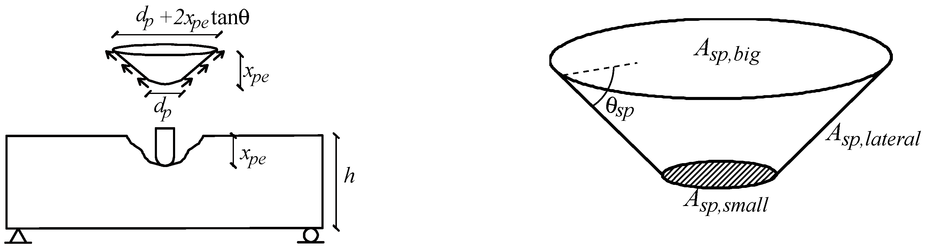
3.2.5. Spalling-Resistant Energy (ESP)

Some impact energy will transfer to a concrete panel, which becomes a part of the concrete panel spall. The spalling shape was normally considered a truncated cone in previous experimental studies. As shown in Figure 8, the idealized concrete failure and spalling-resistant energy are determined from the kinetic energy of the spalled concrete that also has mass (kg) and velocity (m/s), as shown in Equation (99), and the spalled failure is related to drag force (Fdrag) (Equations (100) to (102)) [7]. This kinetic energy is the same as that in the case where the forces acting on the area and volume of the spalled concrete are multiplied (Equation (103)), and is known as energy density (energy/volume).
E S P = 1 2 M s p V s p 2
F d r a g = ρ V s p 2 2 A s p  
F s p = ρ s p V s p 2 2 A s p = V s p 2 2 A s p M s p V o l s p
F s p V o l s p A s p = M s p 2 V s p 2 = E S P
E S P = F s p V o l s p A s p
where ESP is the spalling-resistant energy (J); Msp is the mass of the spalled concrete cone (kg); Fsp is the force between the spalled cone and a concrete slab (N); Vsp is the velocity of the spalled concrete cone (m/s); Volsp is the volume of the idealized concrete cone (mm3); Asp is the projected area of the idealized concrete cone (mm2); and ρsp is the density of the spalled cone (kg/mm3). The volume and area can be obtained from Equations (104) to (107).
V o l s p = π x p e 12 ( 4 x p e 2 tan 2 θ s p + 6 d p x p e tan θ s p + 3 d p 2 )
A s p , b i g = π 4 ( d + 2 x p tan θ s p ) 2
A s p , l i t t e = π d 2 4
A s p , l a t e r a l = π ( d p + x p tan θ s p ) x p cos θ s p
where Volsp is the volume of the spalled cone (mm3); xpe is the penetration depth (mm); dp is the diameter of a projectile (mm); Asp,big is the top area of the spalled cone in Figure 8 (mm2); Asp,litte is the base area of the spalled cone in Figure 8 (mm2); Asp,lateral is the lateral area of the spalled cone in Figure 8 (mm2); and θsp is the slant angle of the lateral surface (degree).
Finally, the spalling-resistant energy formula can be derived as shown in Equations (108) to (111), and the concrete spalling resistance force (Fsp) is defined using the shear stress controlled by compression, which is a spalled cone area. The reinforcing bar’s action is neglected because the spalled cone is pressured under compression in the spalling condition. When the projectile has a long length or hyper velocity, the energy per unit area increases; hence, these effects should be applied to the penetration prediction formula. α1 is the velocity effect factor applied at a velocity greater than 340 m/s. The value of 340 m/s is Mach 1, and if the projectile velocity exceeds 340 m/s, it will be hypersonic. This can lead to a totally different shock phenomenon [47]. Depending on the speed, it can be assumed that the speed of transferring the projectile energy to the concrete will also vary. In addition, if the projectile is slender, the energy per unit area will be increased. The effect factor takes into account the fact that the projectile length is α2. In other words, energy transference velocity and energy per unit area should be considered even with the same kinetic energy.
F s p = 0.7 f c , d y n [ π ( d p + x p e tan θ s ) x p e cos θ s + π d p 2 4 ]
E S P = 0.7 f c , d y n [ π ( d p + x p e tan θ s ) x p e cos θ s + π d p 2 4 ] α 1 α 2 V o l s p A s p , b i g
α 1 = ( V i m p 340 ) 0.15
α 2 = ln ( 0.8 + l p d p )
where Fsp is the force between the spalled cone and the concrete slab (N); f’c,dyn is the compressive strength of the concrete affected by dynamic load; dp is the cross-sectional diameter of a projectile (mm); xpe is the penetration depth (mm); cosθs is the angle of the truncated cone (degree); Volsp is the volume of the spalled cone (mm3); Asp,big is the based area of the spalled cone (mm2); α1 is the velocity effect factor; α2 is the projectile length factor; and lp is the length of a projectile (mm).

3.2.6. Tunneling-Resistant Energy (ET)

When the projectile has a huge energy per unit area by hyper-velocity and/or large mass, it can penetrate deep into the concrete panel. The energy beyond that required for the spalling step can result in tunneling depth (xt). The tunneling-resistant energy (ET) can be obtained using the energy density and bearing bond strength (Equations (112) and (113)). The force acting on the side of the cylindrical tunnel is shown in Equation (114). The impact energy of a projectile can be resisted by the bearing bond strength between the projectile and concrete. According to previous studies [48,49,50], the average bond stress under static loading is 2.2(f’c,st)0.5, which is modified to 2.2(f’c,dyn)0.5 under dynamic loading. This stress is obtained from the interface between a deformed reinforcing bar and concrete. As there are no lugs on the projectile in many cases, the bearing stress should be reduced, and thus, it is assumed to be 50% in this study, as shown in Equation (115). If there are reinforcing bars in line of the projection, the shear stress of the reinforcing bar needs to be considered. Thus, ET can be expressed as Equation (116).
E T = F t A t V t energy   density   of   density + τ d y n x t energy   of   bond
E T = F t x t energy   density   of   tunnel + τ d y n x t energy   of   bond
F t = N p 2 π d p x t 0.7 f c , d y n
τ d y n = 1.1 f c , d y n
E T = ( N p 2 π d p x t 0.7 f c , d y n ) x t energy   density   of   tunnel + 1.1 f c , d y n x t energy   of   bond
where FT is the tunneling-resistant force on the side of the cylindrical tunnel (N); dp is the diameter of a projectile (mm); xt is the length of the tunnel (mm); Np is the nose shape factor; τdyn is the bond stress under the dynamic loading (MPa); ρp is the density of a projectile (kg/m3); At is the cross-sectional area of the tunnel (mm2); and Mp is the mass of a projectile (kg).

3.3. Penetration Depth Formula

The penetration depth can be determined using the energy equilibrium. The kinetic energy (EK) basically equals the sum of the deformed energy of a projectile (EDP), the elastic penetrated energy of a concrete panel (EEP), the overall deformed energy of a slab (ESD), and the spalling-resistant energy of a concrete panel (ESP), as shown in Equation (117), and in special cases, the tunneling-resistant energy (ET) will be added to Equation (117). As the value to be obtained from the impact formula is the penetration depth, the equation of energies can be summarized as shown in Equation (118). If the energy concentration effect (α1α2) is less than 1, the spalling-resistant energy may exceed the kinetic energy, which does not satisfy the law of conservation of energy. Therefore, when the value of the energy concentration effect is less than 1, it is set to be equal to 1, to satisfy the law of energy conservation (Equation (119)). By contrast, when the energy concentration effect exceeds 1, ESP is smaller than EK. As a result, to satisfy the law of energy conservation, the overflow energy produces the tunneling depth. Assuming that the cone shape is hemispherical, to simplify the equation (Figure 9), the final penetration depth can be summarized as shown in Equations (120) to (123). In Equation (116), the tunnel energy is obtained, and the tunneling depth can be obtained by summarizing the tunneling depth (xt) following Equations (124) to (126). Thus, the penetration depth when α1α2 is over 1 is expressed as shown in Equation (127).
E K = E D P + E E P + E S D + E S P + ( E T )
E K E D P E E P E S D = E S P E K
( E K E D P E E P E S D ) = 0.7 f c , d y n [ π ( d + x p e tan θ s ) x p cos θ s + π d p 2 4 ] α 1 α 2 V s c A s p E K
x p e = E S P 6 8 × 0.7 × f c , d y n × α 1 α 2 α 3 × π 3   ( 1 α 1 α 2 )
α 1 = ( V i m p 340 ) 0.15
α 2 = ln ( 0.8 + l p d p )
α 3 = ( h d ) 0.1 + 0.2
( E K E D P E E P E S D ) ( E K E D P E E P E S D ) 1 α 1 α 2 = E T
E T = π d p ( 2 x t 2 + 0.25 d p x t + x t 2 N p τ d y n )
x t = E T π d p ( 2 + N p τ d y n ) + 0.016 d p 2 0.125 d p 2 + N p τ d y n
x p e + x t = E S P 6 8 × 0.7 × f c , d y n × α 1 α 2 α 3 × π 3 + E T π d p ( 2 + N p τ d y n ) + 0.016 d p 2 0.125 d p 2 + N p τ d y n ( for   α 1 α 2 > 1 )
where f’c,dyn is the compressive strength of the concrete affected by the dynamic load; xpe is the penetration depth (mm); α1 is the velocity effect factor; α2 is the projectile length factor; α3 is the factor related to the panel thickness and the diameter of a projectile; dp is the diameter of a projectile (mm); xt is the length of the tunnel (mm); Np is the nose shape factor; τ is the bond stress (MPa); and Mp is the mass of a projectile (kg).

4. Verification of Developed Impact Formula

4.1. Comparison between Test Results and Predictions

There are many impact formulae for assessing the penetration depth, some of which have similar formulations or require further research [5,7,10,51]. Therefore, some representative formulae, such as the modified NDRC, ACE, Hughes, Haldar, UKAEA, UMIST, and Li–Chen impact formulae, are used to compare the degree of accuracy with which the proposed formula in this study predicts the penetration depth. Regarding the evaluation of the proposed formula, 402 experimental results obtained from various experimental programs are used. The impact test data obtained by Forrestal et al. [24,52,53], Frew et al. [54,55], Zhang et al. [56], Almusallam et al. [57], Soe et al. [58], Abdel-Kader and Fouda [59], and Kim [60] are summarized in Table 1. The total number of specimens is 402; the projectile diameter (dp) ranges from 20 to 76 mm; the projectile length (lp) ranges from 24 to 531 mm; the projectile mass (Mp) ranges from 15 g to approximately 13,000 g (13 kg); the impact velocity (Vimp) ranges from 91 to 1358 m/s; the concrete compressive strength (f’c) ranges from 26 to 237 MPa; the concrete slab thickness (h) ranges from 10 to 2740 mm; ρsteel ranges from 0% to 0.75%; and the steel fiber volume fraction (Vf) ranges from 0.5% to 2.33%. Of the considerable experimental data, only general-impact experiment data are used, where the general-impact experiment involves a solid projectile colliding with a concrete panel, which is reinforced with reinforcing bars at the top and/or bottom. Therefore, only the experimental results corresponding to these conditions are used. Some experimental results having special conditions, such as multiple reinforcing layers, steel plates, and an inside-hollow projectile, are excluded. As the concrete failure mechanism is very complex, it is difficult to conclude that a single parameter is the only factor affecting the impact resistance.

4.2. Penetration Depth Assessment

The tested penetrated depth to predicted penetration depth ratios are compared in Table 2 and Figure 10, under the application of the proposed formula, modified NDRC, ACE, Haldar, Hughes, UKAEA, UMIST, and Li–Chen. The penetration depths of the perforated specimens are also used. In Table 2, the data include the specimens in which the penetration depth is measured. The overall average ratios are found to be 1.00, 0.87, 0.85, 1.2, 0.74, 1.13, 1.97, and 1.36 under the application of the proposed formula, modified NDRC, ACE, Haldar, Hughes, UKAEA, UMIST, and Li–Chen, respectively. Even if the overall average ratio for each formula seems to be good, the average value in each test varies (Table 2).
The proposed impact formula predicts the average value well as 1.0. However, the test results of Abdel-Kader and Fouda [59] were predicted to be 0.76 and those of Frew et al. [55] were predicted to be 1.35. The proposed formula is closer to 1 than other formulae, which means that it is better. However, the test specimens used by Abdel-Kader and Fouda [59] and Frew et al. [55] were, respectively, seven and eighteen. If there were more test specimens, the average predicted value might to be closer to 1. Other experimental results are predominantly close to 1.
The modified NDRC formula overestimates the penetration depth as a whole (Figure 10b). The experimental results obtained with small diameter-to-thickness values are particularly underestimated. The ACE formula also overestimates the penetration depth as a whole, and this trend is similar to that of the modified NDRC (Figure 10c). The Haldar and Hughes formulae are very similar and the trend of the tested-to-predicted penetration depth ratio is similar up to the first test results obtained by Kim [60] (Figure 10d,e). For the second and third experiments, conducted by Kim [60], the Haldar formula is predicted to be 1.2 and above. However, the Hughes formula overestimates, as in the first test, and has a trend similar to those of the modified NDRC and ACE formulae. The Haldar formula looks better considering the overall average tested-to-predicted penetration depth ratio, but the Hughes formula predicts consistently for each test, and thus, appears to be a better formula. The UKAEA formula shows a similar trend to that exhibited by the Haldar formula, predicting better results for these test programs (Figure 10f). UMIST underestimates the predicted penetration depth as a whole, and the data points in Figure 10g are scattered widely; thus, there is no other inconsistency in the experiments. The tested-to-predicted penetration depth ratio obtained using Li–Chen’s formula is close to 1.36 (Figure 10h), which slightly underestimates the penetration depth.

4.3. Critical Impact Mechanism

Table 3 shows energy portions for each experiment, where the deformed energy of a projectile accounted for 0.1–7.4% of kinetic energy. The elastic penetrated energy of a concrete panel accounted for 0–3.8% of kinetic energy. The overall deformed energy of a concrete panel accounted for 0–2.7% of kinetic energy. The average sum of spalling-resistant energy and tunneling-resistant energy accounted for 97.9% of kinetic energy, which was the largest proportion in all experiments. The sum of the spalling-resistant and tunneling-resistant energies was overwhelming, while the other energies were small. In other words, EDP, EEP, and ESD can be ignored in the impact mechanism, with EK being applied only to ESP and ET. That is, Equations (120) and (127) can be modified to Equations (128) and (129), respectively.
Table 3 shows the energy portions for each experiment, where the deformed energy of a projectile accounts for 0.1–7.4% of the kinetic energy. The elastic penetrated energy of a concrete panel accounts for 0–3.8% of the kinetic energy. The overall deformed energy of a concrete panel accounts for 0–2.7% of the kinetic energy. The average sum of spalling- and tunneling-resistant energies accounts for 97.9% of the kinetic energy, which is the largest proportion in all experiments. The sum of the spalling- and tunneling-resistant energies is overwhelming, while that of the other energies is small. In other words, EDP, EEP, and ESD can be ignored in the impact mechanism, with EK being applied only to ESP and ET. That is, Equations (120) and (127) can be modified to Equations (128) and (129), respectively.
Figure 11 compares the average tested-to-predicted penetration depth ratios obtained using the detailed formula and the simplified formula. The overall average of the detailed formula decreases by 0.01, from 1.00 to 0.99, but can still be considered equal. The standard deviation for both the detailed and simplified formulae is 0.23. Thus, no significant difference is observed between the detailed formula and simplified formula.
x p e = E K × 6 8 × 0.7 × f c , d y n × α 3 × π 3 = 0.5357 × M p V i m p 2 f c , d y n × α 3 × π 3   ( for   α 1 α 2 1 )
x p e + x t = E K × 6 8 × 0.7 × f c , d y n × α 1 α 2 α 3 × π 3   + ( E K E K / α 1 α 2 ) π d p ( 2 + N p τ d y n ) + 0.016 d p 2 0.125 d p 2 + N p τ d y n   ( for   α 1 α 2 > 1 )
where xpe is the penetration depth (mm); EK is the kinetic energy (N-mm); f’c,dyn is the compressive strength of concrete affected by the dynamic load; α1 is the velocity effect factor; α2 is the projectile length factor; α3 is the ratio of the thickness of a concrete panel to the diameter of a projectile; Mp is the mass of a projectile; Vimp is the impact velocity; τdyn is the bond stress under the dynamic loading; lp is the length of a projectile; dp is the diameter of a projectile; h is the target’s thickness; and Np is the nose shape factor.

5. Conclusions

In this paper, an energy-based impact formula for predicting the penetration depth of a (steel fiber-reinforced) concrete panel under impact loading is derived using various factors and the theoretical background framework. In addition, the new impact formula is verified with impact test results obtained for various test variables. The derivation process and results of comparisons of the newly proposed penetration depth formula are summarized as follows:
  • There are six types of energies involved in the penetration failure of a concrete panel colliding with a high-velocity projectile. These are the kinetic energy of a projectile (EK), deformed energy of a projectile (EDP), elastic penetrated energy of the target concrete panel (EEP), overall deformed energy (ESD), spalling-resistant energy of a concrete panel (ESP), and tunneling-resistant energy (ET), which occurs when the kinetic energy is concentrated by a long projectile and/or high velocity. Using these energies and energy conservation law, a new energy-based penetration depth formula is derived.
  • The spalled cone is related to the shear stress controlled by compression, while the scabbed cone is related to that controlled by tension. These shear stresses must account for the strain rate effect, where the fib Model Code 2010 (fib, 2010) is used in this study. The strain rate is defined as the force applied on the projectile’s nose, as suggested by Forrestal et al. (1994), and is newly derived in this paper by using the theoretical background.
  • The penetration depth formula is derived using the drag force, volume, and area of the spalled cone, which leads to an energy density. The spalling energy can be concentrated by a high velocity and/or a long projectile, and these effects can be applied to the penetration depth formula. The concentrated energy can produce the tunneling depth, which is also derived from the energy density.
  • The accuracy of the new penetration depth formula is examined and compared to the existing impact formulae, such as the modified NDRC, ACE, Haldar, UKAEA, UMIST, and Li–Chen formulae. The mean value of the tested penetration depth compared to the predicted penetration depth of the new impact formula is 1, meaning that it is the best of these impact formulae. The standard deviation of the new impact formula for predicting the penetration depth is 0.23, which is also the best.

Author Contributions

Conceptualization, S.K.; Formal analysis, S.K.; Funding acquisition, T.H.-K.K.; Investigation, S.K.; Methodology, S.K.; Project administration, T.H.-K.K.; Supervision, T.H.-K.K.; Validation, S.K.; Writing—original draft, S.K.; Writing—review & editing, T.H.-K.K. Both authors have read and agreed to the published version of the manuscript.

Funding

This work was supported by the Nuclear Safety Research Program through the Korea Foundation Of Nuclear Safety (KoFONS) using the financial resource granted by the Nuclear Safety and Security Commission (NSSC) of the Republic of Korea. (No2003007).

Acknowledgments

This manuscript is based on the PhD dissertation by Kim [60].

Conflicts of Interest

The authors declare no conflict of interest.

References

  1. Probst, A.D.; Kang, T.H.-K.; Ramseyer, C.; Kim, U. Composite Flexural Behavior of Full-Scale Concrete Filled Tubes without Axial Loads. ASCE J. Struct. Eng. 2010, 136, 1401–1412. [Google Scholar] [CrossRef]
  2. Kang, T.H.-K.; Kim, W.; Massone, L.M.; Galleguillos, T.A. Shear-Flexure Coupling Behavior of Steel Fiber-Reinforced Concrete Beams. ACI Struct. J. 2012, 109, 435–444. [Google Scholar]
  3. Kang, T.H.-K.; Wallace, J.W. Punching of Reinforced and Post-Tensioned Concrete Slab-Column Connections. ACI Struct. J. 2006, 103, 531–540. [Google Scholar]
  4. Lee, C.H. Structural Behavior and Progressive Collapse Prevention under Abnormal Extreme Loading. Mag. Archit. Inst. Korea 2007, 51, 15. (In Korean) [Google Scholar]
  5. Li, Q.M.; Reid, S.R.; Wen, H.M.; Telford, A.R. Local Impact Effects of Hard Missiles on Concrete Targets. Int. J. Impact Eng. 2005, 32, 224–284. [Google Scholar] [CrossRef]
  6. Kim, T.W.; Hahm, H.G. The Strength Properties Activated Granulated Ground Blast Furnace Slag with Aluminum Potassium Sulfate and Sodium Hydroxide. J. Korea Concr. Inst. 2015, 27, 95–102. (In Korean) [Google Scholar] [CrossRef] [Green Version]
  7. Hwang, H.J.; Kim, S.; Kang, T.H.K. Energy-Based Penetration Model for Local Impact Damaged Concrete Members. ACI Struct. J. 2017, 114, 1189–1200. [Google Scholar] [CrossRef]
  8. ACE. Fundamentals of Protective Structures; Technical Report No. AT120 AT1207821; Army Corps of Engineering: Washington, DC, USA, 1946. [Google Scholar]
  9. NDRC. Effect of impact and explosion. In Summary Technical Report of Division 2; National Defense Research Committee: Washington, DC, USA, 1946; Volume 1. [Google Scholar]
  10. Kennedy, R.P. A Review of Procedures for the Analysis and Design of Concrete Structures to Resist Missile Impact Effects. Nucl. Eng. Des. 1976, 37, 183–203. [Google Scholar] [CrossRef]
  11. Haladar, A.; Miller, F.J. Penetration Depth in Concrete for Nondeformable Missiles. Nucl. Eng. Des. 1982, 71, 79–88. [Google Scholar] [CrossRef]
  12. Haldar, A.; Hamieh, H. Local Effect of Solid Missiles on Concrete Structures. ASCE J. Struct. Eng. 1984, 110, 948–960. [Google Scholar] [CrossRef]
  13. Hughes, G. Hard Missile Impact on Reinforced Concrete. Nucl. Eng. Des. 1984, 77, 23–25. [Google Scholar] [CrossRef]
  14. Barr, P. Guidelines for the Design and Assessment of Concrete Structures Subjected to Impact; Technical Report No. SRD-R-439; UK Atomic Energy Authority, Safety and Reliability Directorate: Abingdon, UK, 1990. [Google Scholar]
  15. Reid, S.R.; Wen, H.M. Predicting Penetration, Cone Cracking, Scabbing and Perforation of Reinforced Concrete Targets Struck by Flat-Faced Projectiles; Technical Report No. ME/AM/02.01/TE/G/018507/Z; University of Manchester Institute of Science and Technology (UMIST): Manchester, UK, 2001. [Google Scholar]
  16. BNFL. Appendix H reinforced concrete slab local damage assessment. In R3 Impact Assessment Procedure; Magnox Electric plc & Nuclear Electric Limited: Berkeley, Gloucestershire, UK, 2003; Volume 3. [Google Scholar]
  17. Kong, X.Z.; Wu, H.; Fang, Q.; Peng, Y. Rigid and Eroding Projectile Penetration into Concrete Targets Based on an Extended Dynamic Cavity Expansion Model. Int. J. Impact Eng. 2017, 100, 13–22. [Google Scholar] [CrossRef]
  18. Bishop, R.F.; Hill, R.; Mott, N.F. The Theory of Indentation and Hardness Test. Proc. Phys. Soc. 1945, 57, 147–159. [Google Scholar] [CrossRef]
  19. Li, Q.M.; Tong, D.J. Perforation Thickness and Ballistic Limit of Concrete Target Subjected to Rigid Projectile Impact. J. Eng. Mech. 2003, 129, 1083–1091. [Google Scholar] [CrossRef]
  20. Hopkins, H.G. Dynamic expansion of spherical cavities in metal. In Progress in Solid Mechanics; Sneddon, I.N., Hill, R., Eds.; North-Holland Publishing Company: Amsterdam, North Holland, The Netherlands, 1960; Volume 1. [Google Scholar]
  21. Forrestal, M.J.; Luk, V.K. Dynamic Spherical Cavity-Expansion in a Compressible Elastic-Plastic Solid. J. Appl. Mech. 1988, 55, 275–297. [Google Scholar] [CrossRef]
  22. Luk, V.K.; Forrestal, M.J. Penetration into Semi-Infinite Reinforced-Concrete Targets with Spherical and Ogival Nose Projectiles. Int. J. Impact Eng. 1987, 6, 291–301. [Google Scholar] [CrossRef]
  23. Forrestal, M.J.; Luk, V.K. Penetration into Soil Targets. Int. J. Impact Eng. 1992, 12, 427–444. [Google Scholar] [CrossRef]
  24. Forrestal, M.J.; Altman, B.S.; Cargile, J.D.; Hanchak, S.J. An Empirical Equation for Penetration Depth of Ogive-Nose Projectiles into Concrete Targets. Int. J. Impact Eng. 1994, 15, 395–405. [Google Scholar] [CrossRef]
  25. Li, Q.M.; Chen, X.W. Dimensionless Formulae for Penetration Depth of Concrete Target impacted by a non-deformable Projectile. Int. J. Impact Eng. 2003, 28, 93–116. [Google Scholar] [CrossRef]
  26. Chen, X.W.; Li, Q.M. Deep Penetration of a Non-Deformable Projectile with Different Geometrical Characteristics. Int. J. Impact Eng. 2002, 27, 619–637. [Google Scholar] [CrossRef]
  27. Choi, K.K.; Park, H.G. Shear Strength Model for Interior Flat Plate-Column Connections. J. Korea Concr. Inst. 2010, 22, 345–356. (In Korean) [Google Scholar] [CrossRef] [Green Version]
  28. Choi, K.K.; Kim, S.H.; Kim, D.H.; Park, H.G. Direct Punching Shear Strength Model for Interior Slab-Column Connections and Column Footings with Shear Reinforcement. J. Korea Concr. Inst. 2011, 23, 159–168. (In Korean) [Google Scholar] [CrossRef]
  29. Choi, K.K.; Park, H.G.; Kim, H.M. Shear Strength Model for Slab-Column Connections. J. Korea Concr. Inst. 2010, 22, 585–593. (In Korean) [Google Scholar] [CrossRef] [Green Version]
  30. Choi, K.K.; Shin, D.W.; Park, H.G. Shear-Strength Model for Slab-Column Connections Subjected to Unbalanced Moment. ACI Struct. J. 2014, 111, 491–502. [Google Scholar] [CrossRef]
  31. Park, H.G.; Choi, K.K.; Chung, L. Strain-Based Strength Model for Direct Punching Shear of Interior Slab-Column Connections. Eng. Struct. 2011, 33, 1062–1073. [Google Scholar] [CrossRef]
  32. fib. Model Code for Concrete Structures 2010 (fib Model Code 2010); Ernst & Sohn: Berlin, Germany, 2010. [Google Scholar]
  33. ACI Committee 224. Control of Cracking in Concrete Structures (ACI 224R-01); American Concrete Institute: Farmington Hills, MI, USA, 2001. [Google Scholar]
  34. ACI Committee 318. Building Code Requirement for Structural Concrete and Commentary (ACI 318-19); American Concrete Institute: Farmington Hills, MI, USA, 2019. [Google Scholar]
  35. Musmar, M. Tensile Strength of Steel Fiber Reinforced Concrete. Contemp. Eng. Sci. 2013, 6, 225–237. [Google Scholar] [CrossRef]
  36. Williams, M.S. Modeling of Local Impact Effects on Plain and Reinforced Concrete. ACI Struct. J. 1994, 91, C178–C187. [Google Scholar]
  37. Thoma, K. Predictive Modeling of Dynamic Processes; Springer: New York, NY, USA, 2009. [Google Scholar]
  38. Qi, C.Z.; Wang, M.Y.; Qian, Q.H. Strain-Rate Effects on The Strength and Fragmentation Size of Rocks. Int. J. Impact Eng. 2009, 36, 1355–1364. [Google Scholar] [CrossRef]
  39. Hong, S.; Kang, T.H.K. Dynamic Strength Properties of Concrete and Reinforcing Steel Subject to Extreme Loads. ACI Struct. J. 2016, 113, 983–995. [Google Scholar] [CrossRef]
  40. Ramesh, K.T. High rates and impact experiments. In Springer Handbook of Experimental Solid Mechanics; Sharpe, W.N., Jr., Ed.; Springer: New York, NY, USA, 2008; pp. 929–960. [Google Scholar]
  41. Ramesh, K.T.; Narasimhan, S. Finite Deformations and the Dynamic Measurement of Radial Strains in Compression Kolsky Bar Experiments. Int. J. Solids Struct. 1996, 33, 3723–3738. [Google Scholar] [CrossRef]
  42. Comité Euro-International du Béton (CEB). Concrete Structures Under Impact and Impulsive Loading—Synthesis Report; Technical Report CEB Bulletin No. 187; fib International: Lausanne, Switzerland, 1988. [Google Scholar]
  43. Hertz, H. Über die berührung fester elastischer Körper (On the contact of rigid elastic solids). J. Reine Und Angew. 1881, 92, 156–171. [Google Scholar]
  44. Johnson, K.L. Contact Mechanics; Cambridge University Press: Cambridge, UK, 1985. [Google Scholar]
  45. Hanaor, D.A.H.; Gan, Y.; Einav, I. Contact Mechanics of Fractal Surfaces by Spline Assisted Discretisation. Int. J. Solids Struct. 2015, 59, 121–131. [Google Scholar] [CrossRef]
  46. Sneddon, I.N. The Relation Between Load and Penetration in the Axisymmetric Boussinesq Problem for a Punch of Arbitrary Profile. Int. J. Eng. Sci. 1965, 3, 47–57. [Google Scholar] [CrossRef]
  47. Anderson, J.D., Jr. Hypersonic and High. Temperature Gas. Dynamics, 2nd ed.; American Institute of Aeronautics and Astronautics: Reston, VA, USA, 2006. [Google Scholar]
  48. Eligenhausen, R.; Popov, E.P.; Bertero, V.V. Local Bond. Stress-Slip Relationships of Deformed Bars under Generalized Excitations; Earthquake Engineering Research Council Technical Report No. 83/23; University of California: Berkeley, CA, USA, 1983; p. 162. [Google Scholar]
  49. Lowes, L.N.; Altoontash, A. Modeling Reinforced-Concrete Beam-Column Joints Subjected to Cyclic Loading. ASCE J. Struct. Eng. 2003, 129, 1686–1697. [Google Scholar] [CrossRef]
  50. Hwang, H.-J.; Eom, T.-S.; Park, H.-G. Bond-Slip Relationship of Beam Flexural Bars in Interior Beam-Column Joints. ACI Struct. J. 2015, 112, 827–837. [Google Scholar] [CrossRef]
  51. Kim, S.; Kang, T.H.K.; Yun, H.D. Evaluation of Impact Resistance of Steel Fiber-Reinforced Concrete Panel Using Design Equations. ACI Struct. J. 2017, 114, 911–921. [Google Scholar] [CrossRef]
  52. Forrestal, M.J.; Frew, D.J.; Hanchak, S.J.; Brar, N.S. Penetration of Grout and Concrete Targets with Ogive-Nose Steel Projectiles. Int. J. Impact Eng. 1996, 18, 465–476. [Google Scholar] [CrossRef] [Green Version]
  53. Forrestal, M.J.; Frew, D.J.; Hickerson, J.P.; Rohwer, T.A. Penetration of Concrete Targets with Deceleration-Time Measurements. Int. J. Impact Eng. 2003, 28, 479–497. [Google Scholar] [CrossRef]
  54. Frew, D.J.; Forrestal, M.J.; Cargile, J.D. The Effect of Concrete Target Diameter on Projectile Deceleration and Penetration Depth. Int. J. Impact Eng. 2006, 32, 1584–1594. [Google Scholar] [CrossRef]
  55. Frew, D.J.; Hanchak, S.J.; Green, M.L.; Forrestal, M.J. Penetration of Concrete Targets with Ogive-Nose Steel Rods. Int. J. Impact Eng. 1998, 21, 489–497. [Google Scholar] [CrossRef]
  56. Zhang, M.H.; Shim, V.P.W.; Lu, G.; Chew, C.W. Resistance of High-Strength Concrete to Projectile Impact. Int. J. Impact Eng. 2005, 31, 825–841. [Google Scholar] [CrossRef]
  57. Almusallam, T.H.; Siddiqui, N.A.; Iqbal, R.A.; Abbas, H. Response of Hybrid-Fiber Reinforced Concrete Slabs to Hard Projectile Impact. Int. J. Impact Eng. 2013, 58, 17–30. [Google Scholar] [CrossRef]
  58. Soe, K.T.; Zhang, Y.X.; Zhang, L.C. Impact Resistance of Hybrid-Fiber Engineered Cementitious Composite Panels. Compos. Struct. 2013, 104, 320–330. [Google Scholar] [CrossRef]
  59. Abdel-Kader, M.; Fouda, A. Effect of Reinforcement on the Concrete Panels to Impact of Hard Projectiles. Int. J. Impact Eng. 2014, 63, 1–17. [Google Scholar] [CrossRef]
  60. Kim, S. Impact Resistance of High Performance Concrete Panels under High Velocity Projectile Collision. Ph.D. Thesis, Seoul National University, Seoul, Korea, 2018. [Google Scholar]
Figure 1. Nose shape and definition (redrawn from Chen and Li [26]).
Applsci 10 04964 g001
Figure 2. Energies involved in impact mechanism.
Applsci 10 04964 g002
Figure 3. Stress flow on interface between spalled concrete and slab.
Applsci 10 04964 g003
Figure 4. Stress flow on interface between scabbed concrete and a slab.
Applsci 10 04964 g004
Figure 5. Strength of brittle materials affected by strain-rate (redrawn from Qi et al. [38]).
Applsci 10 04964 g005
Figure 6. Wave propagation diagram (redrawn from Ramesh [40]).
Applsci 10 04964 g006
Figure 7. Hertz contact.
Applsci 10 04964 g007
Figure 8. Spalled cone and truncated shape.
Applsci 10 04964 g008
Figure 9. Idealized spalled cone.
Applsci 10 04964 g009
Figure 10. Ratio of tested to predicted penetration depth (Avg. is the average and SD is the standard deviation).
Applsci 10 04964 g010
Figure 11. Ratio of tested to predicted penetration depth by detailed formula and simplified formula.
Applsci 10 04964 g011
Table 1. Summary of impact test programs.
TestsProjectileConcrete panel
dplpMpVimpNpf’chVfρsteel (%)
Abdel-Kader and Fouda [59]2364175201–354Blunt26100-0.4
Almusallam et al. [57]4011580091–135Sharp29–71900–0.90.75
Soe et al. [58]132415306–658Ogive45–90550–2.33
Frew et al. [54]76531about 13,000164–335Ogive23910–1830
Zhang et al. 56]12.62415620–704Ogive45–2371500–1.5
Forrestal et al. [53]76531about 13,000200–448Ogive23–391220–1830-
Frew et al. [55]20–31203,305478,1600442–1225Ogive58940–3050
Forretal et al. [52]20–31203,305478,1600405–1358Ogive51–63910–2740
Forrestal et al. [24]27242906277–800Ogive32–108760–1830-
Kim [60] (first test)202033270,350Hemisphere29–4230–700.5–2.0
Kim [60] (second test)2020–4033–9095–200Hemisphere, Sharp41–10350–100
Kim [60] (third test)202033200Hemisphere16810–301.5
Total20–7620–53115–13,00091–1358Ogive, Blunt, Sharp, Hemisphere26–23710–27400–2.33
Note: dp is the diameter of a projectile (mm); lp is the length of a projectile (mm); Mp is the mass of a projectile (kg); Vimp is the impact velocity of a projectile (m/s); Np is the nose shape of a projectile; f’c is the compressive strength of concrete (MPa); h is the thickness of a concrete panel target (mm); Vf is the steel fiber volume fraction (%); ρsteel is the bottom reinforcing ratio in bpaneldpanel for each face; bpanel is the width of the specimens (mm); and dpanel is the average effective depth (mm).
Table 2. Average ratio of tested to predicted penetration.
TestsData (ea)Proposed FormulaModified NDRCACEHalarHughesUKAEAUMISTLi–Chen
Abdel-Kader and Fouda [59]70.760.620.560.570.60.640.691.78
Almusallam et al. [57]240.971.091.091.41.011.363.170.84
Soe et al. [58]161.230.770.910.80.580.81.121.27
Frew et al. [54]71.031.851.52.011.871.881.870.48
Zhang et al. [56]330.861.131.351.310.781.161.881.04
Forrestal et al. [53]150.881.621.341.891.631.641.670.58
Frew et al. [55]181.351.591.551.811.411.531.650.91
Forretal et al. [52]181.061.291.271.541.191.31.331.06
Forrestal et al. [24]170.881.271.181.571.131.281.271.08
Kim [60] (first test)860.950.680.710.630.550.761.51.69
Kim [60] (second test)1491.060.650.591.220.531.122.321.47
Kim [60] (third test)120.760.420.311.70.291.592.692.31
Total40210.870.851.20.741.131.971.36
Table 3. Energy portion.
TestEDP/EK (%)EEP/EK (%)ESD/EK (%)(ESP+ET)/EK (%)
Abdel-Kader and Fouda [59] 0.07 (0.06–0.08)0.24 (0.2–0.28)0.04 (0.02–0.06)99.7 (99.6–99.7)
Almusallam et al. [57]0.3 (0.1–0.5)0.7(0.5–1.2)0.198.9 (98.1–99.4)
Soe et al. [58]1.86 (1–4.2)0.2 (0.1–0.5)0.1 (0.1–0.3)97.8 (95.1–98.8)
Frew et al. [54] 0.9 (0.7–1.7)0.2 (0.1–0.4)0.1 (0–0.1)98.8 (97.9–99.2)
Zhang et al. [56]3.3 (0.1–7.4)0.5 (0.3–0.9)0.2 (0.1–0.3)95.9 (91.4–98.7)
Forrestal et al. [53] 1.6 (0.6–4.8)0.2 (0.1–0.5)0.2 (0.1–0.5)98 (94.8–99.2)
Frew et al. [55]1 (0.9–1.3)0.1 (0–0.1)0.1 (0–0.1)98.8 (98.5–99.0)
Forretal et al. [52]1 (0.8–1.4)0.10.1 (0–0.2)98.8 (98.4–99.0)
Forrestal et al. [24]0.8 (0.4–1.3)0.2 (0.1–0.3)0.3 (0.1–0.6)98.7 (98.0–99.2)
Kim [60] (first test)0.20.4 (0.2–0.8)099.3 (98.9–99.6)
Kim [60] (second test)1.2 (0.2–4.6)1.9 (0.4–3.8)0.1 (0–0.3)96.8 (92.2–99.2)
Kim [60] (third test)2.4 (1.9–3.1)1.1 (0.5–2.1)0.4 (0.2–2.7)96 (94–97.1)
Total1.1 (0.1–7.4)0.9 (0–3.8)0.1 (0–2.7)97.9 (91.4–99.6)
Note: EK is the kinetic energy (N-mm); EDP is the deformed energy of a projectile (N-mm); EEP is the elastic penetrated energy of a concrete panel (N-mm); ESD is the overall deformed energy of a concrete panel (N-mm); ESP is the spalling-resistant energy (N-mm); and ET is the tunneling-resistant energy (N-mm).

