Linear Vibration Analysis of Shells Using a Seven-Parameter Spectral/hp Finite Element Model
Abstract
1. Introduction
2. Theoretical Formulation
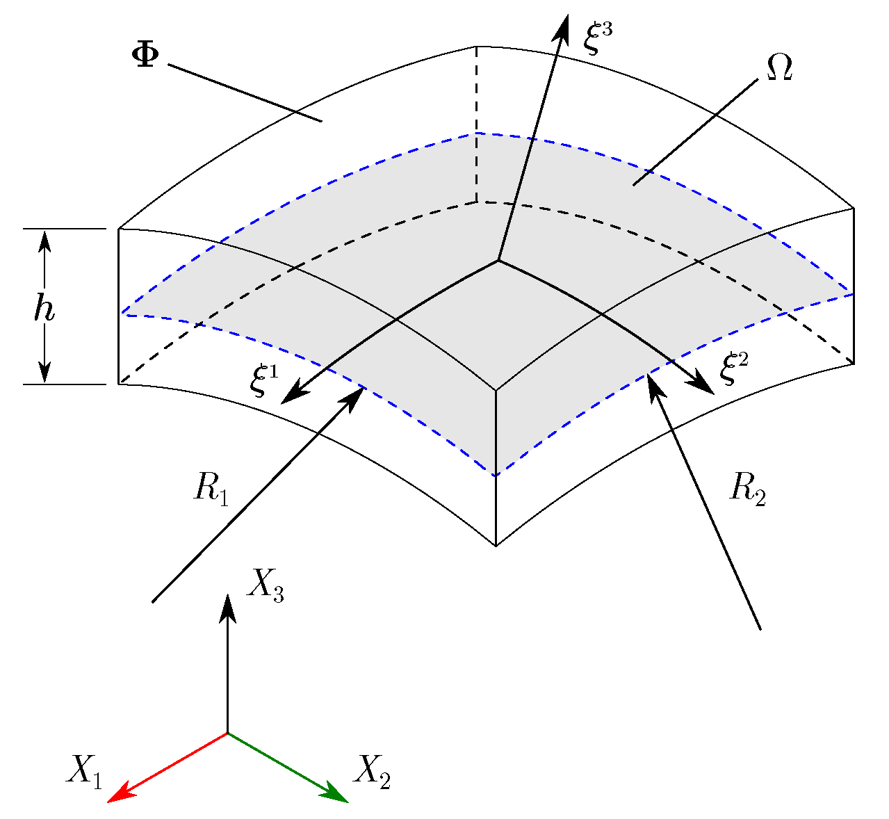
2.1. Geometric Parameters
2.2. Displacement Field
2.3. Strains
3. Constitutive Equations
4. Equations of Motion
5. Finite Element Model
6. Numerical Results
6.1. Convergence Study
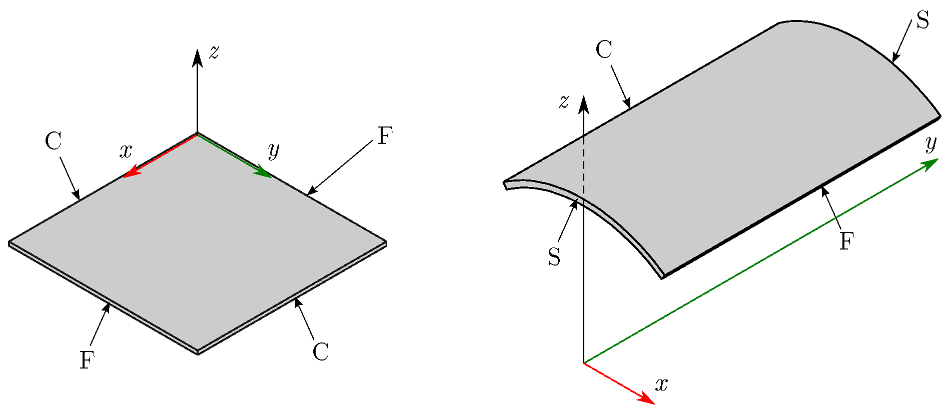
6.1.1. Plates
- I.
- All edges simply-supported (SSSS)
- II.
- Two opposite edges simply-supported and the other two clamped (SCSC)
- III.
- All edges clamped (CCCC)
6.1.2. Shells
- IV.
- All free edges (FF)
- V.
- All clamped edges (CC)
- VI.
- A clamped edge and a free edge (CF)
6.2. Numeric Validation
6.2.1. Plates
6.2.2. Shells
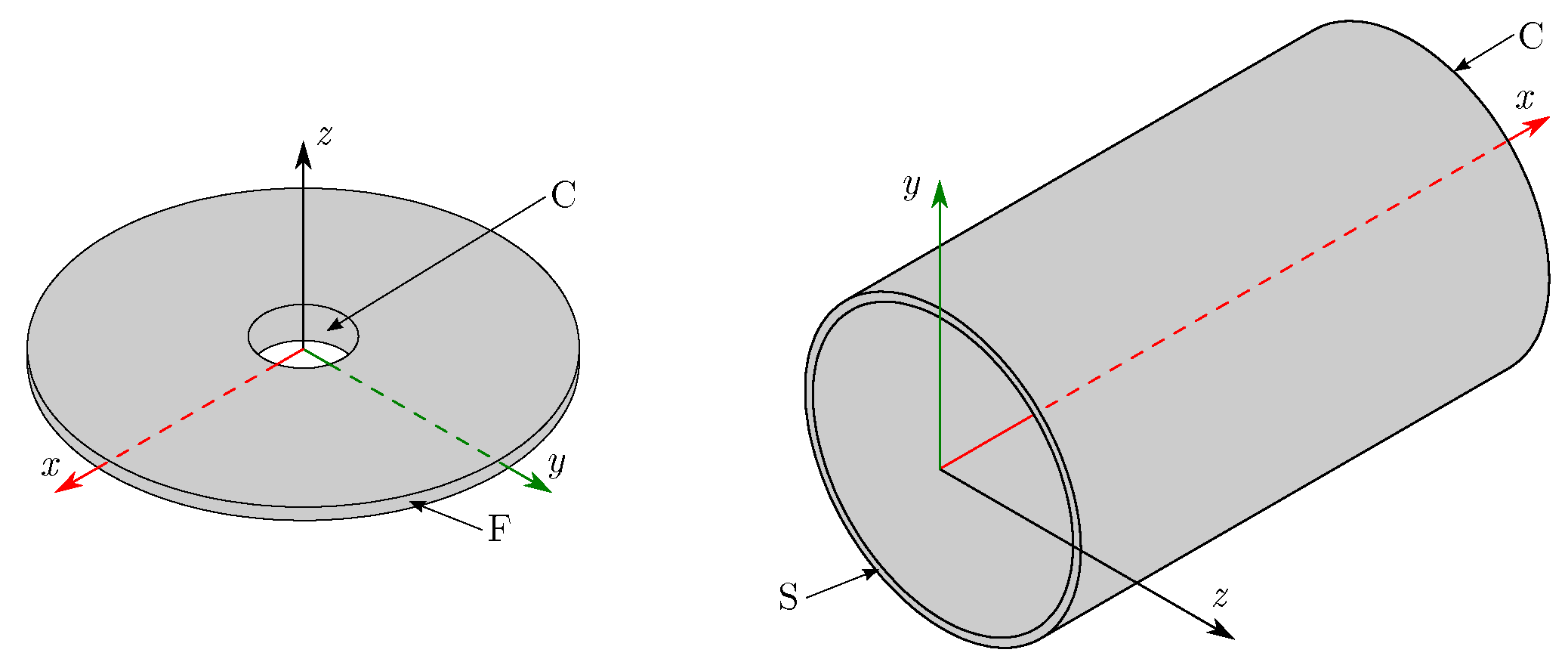
6.3. Numeric Results
- Hemisphere with linear variable thickness, .
- Cylinder with linear variable thickness, .
- Fraction of cylinder with linear variable thickness, .
6.3.1. Hemisphere
6.3.2. Cylinder
6.3.3. Fraction of Cylinder
- Truncated hemisphere: ,
- Cylinder: ,
- Fraction of cylinder: .
7. Conclusions
Author Contributions
Funding
Conflicts of Interest
References
- Reddy, J.N. Theory and Analysis of Elastic Plates and Shells, 2nd ed.; CRC Press: Boca Raton, FL, USA, 2007. [Google Scholar]
- Amabili, M. Nonlinearities in rotation and thickness deformation in a new third-order thickness deformation theory for static and dynamic analysis of isotropic and laminated doubly curved shells. Int. J. Non-Linear Mech. 2015, 69, 109–128. [Google Scholar] [CrossRef]
- Thai, H.T.; Kim, S.E. A review of theories for the modeling and analysis of functionally graded plates and shells. Compos. Struct. 2015, 128, 70–86. [Google Scholar] [CrossRef]
- Mindlin, R.D. Influence of rotatory inertia and shear in flexural motions of isotropic elastic plates. J. Appl. Mech. 1951, 18, 31–38. [Google Scholar]
- Thai, H.T.; Nguyen, T.K.; Vo, T.P.; Ngo, T. A new simple shear deformation plate theory. Compos. Struct. 2017, 171, 277–285. [Google Scholar] [CrossRef]
- Carrera, E.; Brischetto, S. Analysis of thickness locking in classical, refined and mixed theories for layered shells. Compos. Struct. 2008, 85, 83–90. [Google Scholar] [CrossRef]
- Wang, Q.; Shao, D.; Qin, B. A simple first-order shear deformation shell theory for vibration analysis of composite laminated open cylindrical shells with general boundary conditions. Compos. Struct. 2018, 184, 211–232. [Google Scholar] [CrossRef]
- Bischoff, M.; Ramm, E. Shear deformable shell elements for large strains and rotations. Int. J. Numer. Methods Eng. 1997, 40, 4427–4449. [Google Scholar] [CrossRef]
- Reddy, J.N. Mechanics of Laminated Composite Plates and Shells: Theory and Analysis, 2nd ed.; CRC Press: Boca Raton, FL, USA, 2004. [Google Scholar]
- Chapelle, D.; Bathe, K.J. The Finite Element Analysis of Shells—Fundamentals, 2nd ed.; Springer: Berlin/Heidelberg, Geramny, 2011. [Google Scholar]
- Arciniega, R.A.; Reddy, J.N. Tensor-based finite element formulation for geometrically nonlinear analysis of shell structures. Comput. Methods Appl. Mech. Eng. 2007, 196, 1048–1073. [Google Scholar] [CrossRef]
- Sansour, C. A theory and finite element formulation of shells at finite deformations involving thickness change: Circumventing the use of a rotation tensor. Arch. Appl. Mech. 1995, 65, 194–216. [Google Scholar] [CrossRef]
- Hahn, Y.; Kikuchi, N. Mixed shell element for seven-parameter formulation. Int. J. Numer. Methods Eng. 2005, 64, 95–124. [Google Scholar] [CrossRef][Green Version]
- Payette, G.S.; Reddy, J.N. A seven-parameter spectral/hp finite element formulation for isotropic, laminated composite and functionally graded shell structures. Comput. Methods Appl. Mech. Eng. 2014, 278, 664–704. [Google Scholar] [CrossRef]
- Reddy, J.N. An Introduction to Nonlinear Finite Element Analysis: With Applications to Heat Transfer, Fluid Mechanics, and Solid Mechanics, 2nd ed.; Oxford University Press: Oxford, UK, 2015. [Google Scholar]
- Cugnoni, J.; Gmur, T.; Schorderet, A. Identification by modal analysis of composite structures modelled with FSDT and HSDT laminated shell finite elements. Compos. Part A Appl. Sci. Manuf. 2004, 35, 977–987. [Google Scholar] [CrossRef]
- Park, T.; Kidu, K.; Han, S. Linear static and dynamic analysis of laminated composite plates and shells using a 4-node quasi-conforming shell element. Compos. Part B Eng. 2005, 37, 237–248. [Google Scholar] [CrossRef]
- Jung, W.Y.; Han, S.C. Transient analysis of FGM and laminated composite structures using a refined 8-node ANS shell element. Compos. Part B Eng. 2014, 56, 372–383. [Google Scholar] [CrossRef]
- Sahoo, S.S.; Panda, S.K.; Mahapatra, T.R. Static, free vibration and transient response of laminated composite curved shallow panel – An experimental approach. Eur. J. Mech. A/Solids 2016, 59, 95–113. [Google Scholar] [CrossRef]
- Hirwani, C.K.; Patil, R.K.; Panda, S.K.; Mahapatra, S.S.; Mandal, S.K.; Srivastava, L.; Buragohain, M.K. Experimental and numerical analysis of free vibration of delaminated curved panel. Aerosp. Sci. Technol. 2016, 54, 353–370. [Google Scholar] [CrossRef]
- Biswal, D.K.; Mohanty, S.C. Free vibration and damping characteristics study of doubly curved sandwich shell panels with viscoelastic core and isotropic/laminated constraining layer. Eur. J. Mech. A/Solids 2018, 72, 424–439. [Google Scholar] [CrossRef]
- Moita, J.S.; Araújo, A.L.; Soares, C.M.M.; Soares, C.A.M. Vibration analysis of functionally graded material sandwich structures with passive damping. Compos. Struct. 2018, 183, 407–415. [Google Scholar] [CrossRef]
- Kant, T.; Kumar, S.; Singh, U. Shell dynamics with three-dimensional degenerate finite elements. Comput. Struct. 1994, 50, 135–146. [Google Scholar] [CrossRef][Green Version]
- Bardell, N.S.; Dunsdon, J.M.; Langley, R.S. Free vibration of thin, isotropic, open, conical panels. J. Sound Vib. 1998, 217, 297–320. [Google Scholar] [CrossRef]
- Lee, S.J.; Han, S.E. Free-vibration analysis of plates and shells with a nine-node assumed natural degenerated shell element. J. Sound Vib. 2001, 241, 605–633. [Google Scholar] [CrossRef]
- Lee, W.H.; Han, S.C. Free and forced vibration analysis of laminated composite plates and shells using a 9-node assumed strain shell element. Comput. Mech. 2006, 39, 41–58. [Google Scholar] [CrossRef]
- Bahrami, S.; Shirmohammadi, F.; Saadatpour, M.M. Vibration analysis of thin shallow shells using spectral element method. Appl. Math. Model. 2017, 44, 470–480. [Google Scholar] [CrossRef]
- Tornabene, F.; Fantuzzi, N.; Bacciocchi, M. The local GDQ method for the natural frequencies of doubly-curved shells with variable thickness: A general formulation. Compos. Part B Eng. 2016, 92, 265–289. [Google Scholar] [CrossRef]
- Żak, A.; Krawczuk, M. A higher order transversely deformable shell-type spectral finite element for dynamic analysis of isotropic structures. Finite Elem. Anal. and Des. 2018, 142, 17–29. [Google Scholar] [CrossRef]
- Ganesan, N.; Sivadas, K.R. Free vibration of cantilever circular cylindrical shells with variable thickness. Comput. Struct. 1990, 34, 669–677. [Google Scholar] [CrossRef]
- Sivadas, K.R.; Ganesan, N. Free vibration of circular cylindrical shells with axially varying thickness. J. Sound Vib. 1991, 147, 73–85. [Google Scholar] [CrossRef]
- Kang, J.H.; Leissa, A.W. Three-dimensional vibrations of thick spherical shell segments with variable thickness. Int. J. Solids Struct. 2000, 37, 4811–4823. [Google Scholar] [CrossRef]
- El-Kaabazi, N.; Kennedy, D. Calculation of natural frequencies and vibration modes of variable thickness cylindrical shells using the Wittrick–Williams algorithm. Comput. Struct. 2012, 104, 4–12. [Google Scholar] [CrossRef]
- Dai, L.; Yang, T.; Du, J.; Li, W.L.; Brennan, M.J. An exact series solution for the vibration analysis of cylindrical shells with arbitrary boundary conditions. Appl. Acoust. 2013, 74, 440–449. [Google Scholar] [CrossRef]
- Bacciocchi, M.; Eisenberger, M.; Fantuzzi, N.; Tornabene, F.; Viola, E. Vibration analysis of variable thickness plates and shells by the Generalized Differential Quadrature method. Compos. Struct. 2016, 156, 218–237. [Google Scholar] [CrossRef]
- Karniadakis, G.E.; Sherwin, S. Spectral/hp Element Methods for CFD; Oxford University Press: Oxford, UK, 1999. [Google Scholar]
- Pozrikidis, C. Introduction to Finite and Spectral Element Methods Using MATLAB; Chapman and Hall/CRC Press: Boca Raton, FL, USA, 2014. [Google Scholar]
- Gutierrez Rivera, M.; Reddy, J.N. Nonlinear transient and thermal analysis of functionally graded shells using a seven-parameter shell element. J. Modeling Mech. Mater. 2017, 1. [Google Scholar] [CrossRef]
- Gutierrez Rivera, M.; Reddy, J.N. Stress analysis of functionally graded shells using a 7-parameter shell element. Mech. Res. Commun. 2016, 78, 60–70. [Google Scholar] [CrossRef]
- Reddy, J.N. An Introduction to the Finite Element Method, 3rd ed.; McGraw-Hill: New York, NY, USA, 2005. [Google Scholar]
- Reddy, J.N. Energy Principles and Variational Methods in Applied Mechanics, 2nd ed.; John Wiley & Sons: Hoboken, NJ, USA, 2017. [Google Scholar]
- Guennebaud, G.; Jacob, B. Eigen v3. Available online: http://eigen.tuxfamily.org (accessed on 24 July 2020).
- Reddy, J.N.; Phan, N.D. Stability and vibration of isotropic, orthotropic and laminated plates according to a higher-order shear deformation theory. J. Sound Vib. 1985, 98, 157–170. [Google Scholar] [CrossRef]
- Liew, K.M.; Xiang, Y.; Kitipornchai, S.; Wang, C.M. Vibration Of Thick Skew Plates Based On Mindlin Shear Deformation Plate Theory. J. Sound Vib. 1993, 168, 39–69. [Google Scholar] [CrossRef]
- Liew, K.M.; Hung, K.C.; Lim, M.K. A continuum three-dimensional vibration analysis of thick rectangular plates. Int. J. Solids Struct. 1993, 30, 3357–3379. [Google Scholar] [CrossRef]
- Shufrin, I.; Eisenberger, M. Stability and vibration of shear deformable plates –first order and higher order analyses. Int. J. Solids Struct. 2005, 42, 1225–1251. [Google Scholar] [CrossRef]
- Shufrin, I.; Eisenberger, M. Vibration of shear deformable plates with variable thickness – first-order and higher-order analyses. Int. J. Solids Struct. 2006, 290, 465–489. [Google Scholar] [CrossRef]
- Chopra, I.; Durvasula, S. Natural frequencies and modes of tapered skew plates. Int. J. Mech. Sci. 1971, 13, 935–944. [Google Scholar] [CrossRef]
- Mizusawa, T. Vibration of rectangular Mindlin plates with tapered thickness by the spline strip method. Comput. Struct. 1993, 46, 451–463. [Google Scholar] [CrossRef]
- Blevins, R.D. Formulas for Natural Frequency and Mode Shape; RE Krieger: Malabar, FL, USA, 1979. [Google Scholar]
- Kang, J.H.; Leissa, A.W. Corrigendum to “Three-dimensional vibrations of thick spherical shell segments with variable thickness” [International Journal of Solids and Structures 37 (2000) 4811-4823]. Int. J. Solids Struct. 2006, 43, 2848–2851. [Google Scholar] [CrossRef][Green Version]


| B.C. | Mesh Size | Dimensionless Frequency Parameter | ||||||||||
|---|---|---|---|---|---|---|---|---|---|---|---|---|
| SSSS | 10 | 4 | 1.8850 | 4.6013 | 4.6013 | 7.0535 | 8.1524 | 8.7411 | 8.7411 | 8.8824 | 8.8935 | 9.2255 |
| 16 | 1.8768 | 4.5881 | 4.5881 | 7.0230 | 8.1452 | 8.6764 | 8.6764 | 8.7754 | 8.7886 | 9.2255 | ||
| 36 | 1.8758 | 4.5866 | 4.5866 | 7.0193 | 8.1452 | 8.6764 | 8.6764 | 8.7731 | 8.7864 | 9.2255 | ||
| 64 | 1.8757 | 4.5864 | 4.5864 | 7.0187 | 8.1452 | 8.6764 | 8.6764 | 8.7728 | 8.7861 | 9.2255 | ||
| SCSC | 10 | 4 | 2.7475 | 5.0590 | 5.9661 | 6.2146 | 8.2245 | 9.1435 | 10.6854 | 10.9426 | 10.9804 | 11.7858 |
| 16 | 2.7289 | 5.0420 | 5.9548 | 6.1604 | 8.1746 | 9.0403 | 10.6534 | 10.7096 | 10.9684 | 11.7122 | ||
| 36 | 2.7236 | 5.0379 | 5.9524 | 6.1481 | 8.1632 | 9.0368 | 10.6470 | 10.6881 | 10.9667 | 11.7026 | ||
| 64 | 2.7212 | 5.0362 | 5.9515 | 6.1425 | 8.1584 | 9.0357 | 10.6450 | 10.6795 | 10.9663 | 11.6989 | ||
| CCCC | 10 | 4 | 3.4000 | 6.5599 | 6.5599 | 9.2440 | 11.0969 | 11.2003 | 12.5671 | 12.5671 | 13.4031 | 13.4031 |
| 16 | 3.3754 | 6.5062 | 6.5062 | 9.1816 | 10.8716 | 10.9702 | 12.5399 | 12.5399 | 13.2043 | 13.2043 | ||
| 36 | 3.3676 | 6.4928 | 6.4928 | 9.1648 | 10.8503 | 10.9478 | 12.5351 | 12.5351 | 13.1818 | 13.1818 | ||
| 64 | 3.3638 | 6.4864 | 6.4864 | 9.1569 | 10.8415 | 10.9384 | 12.5340 | 12.5340 | 13.1721 | 13.1721 | ||
| B.C. | Mesh Size | Dimensionless Frequency Parameter | ||||||||||
|---|---|---|---|---|---|---|---|---|---|---|---|---|
| λ1 | λ2 | λ3 | λ4 | λ5 | λ6 | λ7 | λ8 | λ9 | λ10 | |||
| SSSS (LTV) | 20 | 4 | 1.4395 | 3.4873 | 3.5268 | 5.4898 | 6.7130 | 6.9748 | 8.0993 | 8.5927 | 8.7670 | 8.7840 |
| 16 | 1.4317 | 3.4744 | 3.5049 | 5.4478 | 6.6048 | 6.7935 | 8.0989 | 8.5679 | 8.5920 | 8.6508 | ||
| 36 | 1.4304 | 3.4720 | 3.5028 | 5.4424 | 6.6003 | 6.7904 | 8.0989 | 8.5599 | 8.5920 | 8.6431 | ||
| 64 | 1.4301 | 3.4714 | 3.5023 | 5.4411 | 6.5991 | 6.7898 | 8.0989 | 8.5581 | 8.5920 | 8.6412 | ||
| SCSC (LTV) | 20 | 4 | 2.0928 | 3.8518 | 4.8478 | 5.9363 | 6.4744 | 6.9981 | 8.9493 | 9.4589 | 10.4564 | 10.6023 |
| 16 | 2.0773 | 3.8307 | 4.7784 | 5.9253 | 6.3929 | 6.8794 | 8.4973 | 9.2892 | 10.0036 | 10.5687 | ||
| 36 | 2.0730 | 3.8265 | 4.7678 | 5.9229 | 6.3816 | 6.8740 | 8.4780 | 9.2778 | 9.9834 | 10.5607 | ||
| 64 | 2.0710 | 3.8247 | 4.7629 | 5.9219 | 6.3768 | 6.8721 | 8.4696 | 9.2735 | 9.9751 | 10.5578 | ||
| CCCC (LTV) | 10 | 4 | 3.0223 | 5.8861 | 5.8973 | 8.3730 | 10.0989 | 10.2055 | 12.2775 | 12.2962 | 12.5543 | 12.5610 |
| 16 | 2.9998 | 5.8341 | 5.8439 | 8.3088 | 9.8615 | 9.9473 | 12.0541 | 12.0675 | 12.5249 | 12.5317 | ||
| 36 | 2.9836 | 5.8057 | 5.8155 | 8.2721 | 9.8170 | 9.9016 | 12.0050 | 12.0183 | 12.5057 | 12.5126 | ||
| 64 | 2.9804 | 5.8001 | 5.8098 | 8.2649 | 9.8086 | 9.8930 | 11.9957 | 12.0090 | 12.5042 | 12.5112 | ||
| CCCC (PTV) | 20 | 4 | 2.3831 | 4.4976 | 4.7480 | 6.7065 | 7.7330 | 8.4742 | 9.9484 | 10.2233 | 12.6720 | 12.8649 |
| 16 | 2.3655 | 4.4543 | 4.6832 | 6.6283 | 7.5201 | 8.0129 | 9.7064 | 9.7584 | 11.3271 | 12.1759 | ||
| 36 | 2.3533 | 4.4315 | 4.6585 | 6.5960 | 7.4785 | 7.9704 | 9.6596 | 9.7117 | 11.2627 | 12.1013 | ||
| 64 | 2.3508 | 4.4267 | 4.6539 | 6.5896 | 7.4706 | 7.9628 | 9.6507 | 9.7029 | 11.2503 | 12.0891 | ||
| Mesh Size | Dimensionless Frequency Parameter | ||||||||||
|---|---|---|---|---|---|---|---|---|---|---|---|
| Λ1 | Λ2 | Λ3 | Λ4 | Λ5 | Λ6 | Λ7 | Λ8 | Λ9 | Λ10 | ||
| 16 | 0.3334 | 0.3382 | 0.8548 | 0.8583 | 0.9198 | 0.9198 | 1.5180 | 1.5671 | 1.5671 | 1.8278 | |
| (constant) | 36 | 0.3296 | 0.3296 | 0.8510 | 0.8510 | 0.8586 | 0.8621 | 1.5180 | 1.5433 | 1.5433 | 1.5669 |
| 49 | 0.3293 | 0.3293 | 0.8507 | 0.8507 | 0.8568 | 0.8568 | 1.5180 | 1.5245 | 1.5245 | 1.5669 | |
| 64 | 0.3292 | 0.3292 | 0.8507 | 0.8507 | 0.8556 | 0.8556 | 1.5168 | 1.5180 | 1.5188 | 1.5669 | |
| 16 | 0.3462 | 0.3511 | 0.7477 | 0.7510 | 1.0126 | 1.0126 | 1.5319 | 1.5690 | 1.5690 | 1.7936 | |
| (variable) | 36 | 0.3419 | 0.3419 | 0.7445 | 0.7445 | 0.9485 | 0.9518 | 1.5319 | 1.5688 | 1.5688 | 1.7362 |
| 49 | 0.3415 | 0.3415 | 0.7442 | 0.7442 | 0.9465 | 0.9465 | 1.5319 | 1.5688 | 1.5688 | 1.7280 | |
| 64 | 0.3414 | 0.3414 | 0.7442 | 0.7442 | 0.9453 | 0.9453 | 1.5319 | 1.5688 | 1.5688 | 1.7207 | |
| B.C. | Mesh Size | Natural Frequency | |||||||||||
|---|---|---|---|---|---|---|---|---|---|---|---|---|---|
| f1 | f2 | f3 | f4 | f5 | f6 | f7 | f8 | f9 | f10 | f11 | f12 | ||
| CC | 1 | 943.46 | 1113.20 | 1902.29 | 1902.82 | 1907.98 | 2049.30 | 3109.91 | 3229.87 | 3256.72 | 3888.11 | 3889.17 | 4391.09 |
| 4 | 904.81 | 905.10 | 913.04 | 932.30 | 1405.74 | 1416.29 | 1889.70 | 1889.70 | 1921.01 | 2026.41 | 2027.24 | 2059.93 | |
| 9 | 897.71 | 897.83 | 902.03 | 902.03 | 1393.46 | 1393.53 | 1510.55 | 1510.55 | 1685.00 | 1685.00 | 1885.93 | 1885.93 | |
| 16 | 896.96 | 896.96 | 901.15 | 901.15 | 1392.09 | 1392.09 | 1500.38 | 1500.93 | 1675.61 | 1676.11 | 1884.77 | 1884.77 | |
| CF | 1 | 471.25 | 471.40 | 556.39 | 781.57 | 968.38 | 1154.96 | 1614.93 | 2031.64 | 2055.70 | 2056.21 | 2184.61 | |
| 4 | 316.28 | 317.29 | 469.22 | 469.22 | 785.62 | 808.72 | 930.65 | 939.13 | 939.41 | 948.56 | 1462.88 | ||
| 9 | 315.38 | 315.38 | 468.52 | 468.52 | 768.22 | 768.37 | 914.46 | 914.58 | 937.50 | 937.50 | 1451.27 | ||
| 16 | 315.31 | 315.31 | 468.26 | 468.26 | 767.59 | 767.59 | 913.77 | 913.77 | 937.01 | 937.01 | 1450.34 | ||
| Thickness Variation | Mesh Size | Natural Frequency | ||||||||||
|---|---|---|---|---|---|---|---|---|---|---|---|---|
| f1 | f2 | f3 | f4 | f5 | f6 | f7 | f8 | f9 | f10 | f11 | ||
| Linear | 4 | 1207.35 | 1421.01 | 1562.11 | 1565.90 | 1926.52 | 2504.34 | 2731.78 | 2731.91 | 3823.94 | 3866.67 | 3879.78 |
| 16 | 1132.68 | 1132.69 | 1162.82 | 1162.82 | 1467.54 | 1488.30 | 1567.27 | 1567.27 | 1987.23 | 1987.23 | 2644.84 | |
| 25 | 1132.38 | 1132.38 | 1160.26 | 1160.50 | 1462.59 | 1462.59 | 1567.05 | 1567.05 | 1905.66 | 1905.66 | 2455.58 | |
| 36 | 1132.28 | 1132.28 | 1160.12 | 1160.12 | 1460.54 | 1460.96 | 1566.91 | 1566.91 | 1896.33 | 1896.33 | 2416.55 | |
| Linear symmetric | 4 | 1268.97 | 1316.57 | 1320.46 | 1577.64 | 2199.21 | 2259.86 | 2260.21 | 3135.01 | 3738.82 | 3796.26 | 3882.94 |
| 16 | 1107.47 | 1107.58 | 1313.82 | 1313.82 | 1380.46 | 1380.46 | 1873.68 | 1901.42 | 2258.84 | 2258.84 | 2501.53 | |
| 25 | 1107.12 | 1107.12 | 1313.50 | 1313.50 | 1376.88 | 1377.28 | 1866.73 | 1866.73 | 2258.27 | 2258.27 | 2411.96 | |
| 36 | 1107.08 | 1107.08 | 1313.58 | 1313.58 | 1376.71 | 1376.71 | 1864.07 | 1864.62 | 2258.51 | 2258.51 | 2401.38 | |
| Dimensionless Frequency Parameter | Formulation | ||||||
|---|---|---|---|---|---|---|---|
| Present | Reddy & Phan [43] | Liew [44] (FOPT) | Liew [45] (3D) | Shufrin [46] (FOPT) | Shufrin [46] (HOPT) | 3D 172,800 | |
| 1.8758 | 1.9311 | 1.9311 | 1.9342 | 1.9311 | 1.9317 | 1.8424 | |
| (2.86) | (2.86) | (3.02) | (2.86) | (2.89) | (1.81) | ||
| 4.5866 | 4.6077 | 4.605 | 4.6222 | 4.6050 | 4.6088 | 4.4577 | |
| (0.46) | (0.40) | (0.77) | (0.40) | (0.48) | (2.89) | ||
| 4.5866 | 4.6077 | 4.605 | 4.6222 | 4.6050 | 4.6088 | 4.4577 | |
| (0.46) | (0.40) | (0.77) | (0.40) | (0.48) | (2.89) | ||
| 7.0193 | 7.0724 | 7.0642 | 7.1030 | 7.0642 | 7.0732 | 6.7263 | |
| (0.75) | (0.64) | (1.18) | (0.64) | (0.76) | (4.36) | ||
| 8.1452 | - | - | - | - | - | 8.1454 | |
| (0.002) | |||||||
| 8.6764 | - | - | - | - | - | 8.3994 | |
| (3.30) | |||||||
| 8.6764 | - | - | - | - | - | 8.4148 | |
| (3.11) | |||||||
| 8.7731 | 8.6153 | 8.6055 | 8.6617 | 8.6054 | 8.6188 | 8.6739 | |
| (1.83) | (1.95) | (1.29) | (1.95) | (1.79) | (1.14) | ||
| 8.7864 | 8.6153 | 8.6055 | 8.6617 | 8.6054 | 8.6188 | 8.6739 | |
| (1.99) | (2.10) | (1.44) | (2.10) | (1.94) | (1.30) | ||
| 9.2255 | - | - | - | - | - | 9.2259 | |
| (0.004) | |||||||
| 10.4887 | 10.8101 | 10.7932 | 10.8790 | 10.7932 | 10.8145 | 10.3310 | |
| (2.97) | (2.82) | (3.59) | (2.82) | (3.01) | (1.53) | ||
| 10.9272 | 10.8101 | 10.7932 | 10.8790 | 10.7932 | 10.8145 | 10.3310 | |
| (1.08) | (1.24) | (0.44) | (1.24) | (1.04) | (5.77) | ||
| 10.9272 | - | - | - | - | - | 10.4821 | |
| (4.25) | |||||||
| Dimensionless Frequency Parameter | Formulation | |||
|---|---|---|---|---|
| Present | Liew [44] (FOPT) | Liew [45] (3D) | 3D 172,800 | |
| 2.7236 | 2.6998 | 2.7188 | 2.6808 | |
| (0.88) | (0.18) | (1.60) | ||
| 5.0379 | 4.9714 | 5.0110 | 4.9098 | |
| (1.34) | (0.54) | (2.61) | ||
| 5.9524 | 5.9904 | 6.0522 | 5.9492 | |
| (0.63) | (1.65) | (0.05) | ||
| 6.1481 | - | 6.5234 | 5.9955 | |
| (5.75) | (2.54) | |||
| 8.1632 | 7.9730 | 8.0513 | 7.8849 | |
| (2.39) | (1.39) | (3.53) | ||
| 9.0368 | 8.7873 | 8.8528 | 8.6754 | |
| (2.84) | (2.08) | (4.17) | ||
| 10.6470 | 10.2501 | 10.3860 | 10.3285 | |
| (3.87) | (2.51) | (3.08) | ||
| 10.6881 | - | - | 10.6326 | |
| (0.52) | ||||
| 10.9667 | - | - | 10.9622 | |
| (0.04) | ||||
| 11.7026 | 11.3338 | 11.4510 | 11.1587 | |
| (3.25) | (2.20) | (4.874) | ||
| 11.7732 | 12.024 | 11.5170 | 11.7670 | |
| (2.09) | (2.22) | (0.05) | ||
| 12.5019 | - | 12.1810 | 11.9813 | |
| (2.63) | (4.34) | |||
| 13.1770 | - | 13.0470 | 13.1662 | |
| (1.00) | (0.08) | |||
| Dimensionless Frequency Parameter | Formulation | |||||
|---|---|---|---|---|---|---|
| Present | Liew [44] (FOPT) | Liew [45] (3D) | Shufrin [46] (FOPT) | Shufrin [46] (HOPT) | 3D 400,000 | |
| 3.3676 | 3.2921 | 3.3215 | 3.2978 | 3.3046 | 3.3176 | |
| (2.29) | (1.39) | (2.12) | (1.91) | (1.51) | ||
| 6.4928 | 6.2761 | 6.3457 | 6.2877 | 6.3123 | 6.3419 | |
| (3.45) | (2.32) | (3.26) | (2.86) | (2.38) | ||
| 6.4928 | 6.2761 | 6.3457 | 6.2877 | 6.3123 | 6.3419 | |
| (3.45) | (2.32) | (3.26) | (2.86) | (2.38) | ||
| 9.1648 | 8.7934 | 8.9030 | 8.8127 | 8.8594 | 8.8982 | |
| (4.22) | (2.94) | (4.00) | (3.45) | (3.00) | ||
| 10.8503 | 10.3570 | 10.4990 | 10.4299 | 10.4946 | 10.4996 | |
| (4.76) | (3.35) | (4.03) | (3.39) | (3.34) | ||
| 10.9478 | 10.4561 | 10.5980 | 10.4299 | 10.4946 | 10.5988 | |
| (4.70) | (3.30) | (4.97) | (4.32) | (3.29) | ||
| 12.5351 | 12.5246 | 12.5220 | 12.5568 | 12.6471 | 12.5194 | |
| (0.08) | (0.10) | (0.17) | (0.89) | (0.13) | ||
| 12.5351 | 12.5246 | 12.5220 | 12.5568 | 12.6471 | 12.5194 | |
| (0.08) | (0.10) | (0.17) | (0.89) | (0.13) | ||
| 13.1818 | - | 12.7060 | - | - | 12.7053 | |
| (3.74) | (3.75) | |||||
| 13.1818 | - | 12.7060 | - | - | 12.7053 | |
| (3.74) | (3.75) | |||||
| 14.8717 | - | 14.8700 | - | - | 14.8712 | |
| (0.01) | (0.003) | |||||
| 16.1611 | - | - | 15.8491 | 15.9868 | 15.5110 | |
| (1.97) | (1.09) | (4.19) | ||||
| 16.1611 | - | - | - | - | 15.5110 | |
| (4.19) | ||||||
| Dimensionless Frequency Parameter | Formulation | ||||
|---|---|---|---|---|---|
| Present | Chopra [48] | Mizusawa [49] | Bacciocchi [35] | 3D 400,000 | |
| 1.4304 | 1.4798 | 1.4504 | 1.404 | 1.3943 | |
| (3.33) | (1.38) | (1.88) | (2.59) | ||
| 3.4720 | 3.6354 | 3.4743 | 3.4743 | 3.3959 | |
| (4.49) | (0.06) | (0.07) | (2.24) | ||
| 3.5028 | 3.6755 | 3.5058 | 3.5058 | 3.4176 | |
| (4.70) | (0.09) | (0.09) | (2.49) | ||
| 5.4424 | 5.9040 | 5.484 | 5.4838 | 5.2862 | |
| (7.82) | (0.76) | (0.75) | (2.95) | ||
| 6.6003 | 7.0800 | 6.5347 | 6.5345 | 6.4379 | |
| (6.78) | (1.00) | (1.01) | (2.52) | ||
| 6.7904 | 7.3250 | 6.7039 | 6.7038 | 6.5949 | |
| (7.30) | (1.29) | (1.29) | (2.97) | ||
| 8.0989 | - | - | - | 8.0718 | |
| (0.34) | |||||
| 8.5599 | - | - | - | 8.2568 | |
| (3.67) | |||||
| 8.5920 | - | 8.5302 | 8.5303 | 8.3459 | |
| (0.72) | (0.72) | (2.95) | |||
| 8.6431 | - | - | 8.5921 | 8.58 | |
| (0.59) | (0.74) | ||||
| 8.9568 | 9.5500 | - | - | (8.944) | |
| (6.21) | (0.14) | ||||
| 9.3862 | 9.6350 | - | - | 9.3532 | |
| (2.58) | (0.35) | ||||
| Dimensionless Frequency Parameter | Formulation | |||
|---|---|---|---|---|
| Present | Blevins [50] | Mizusawa [49] | 3D 324,000 | |
| 2.0730 | 2.1460 | 2.0457 | 2.0307 | |
| (3.40) | (1.33) | (2.08) | ||
| 3.8265 | - | 3.7950 | 3.7564 | |
| (0.83) | (1.86) | |||
| 4.7678 | - | 4.6714 | 4.6667 | |
| (3.40) | (2.17) | |||
| 5.9229 | - | - | 5.9004 | |
| (0.38) | ||||
| 6.3816 | - | 6.2870 | 6.2264 | |
| (1.50) | (2.49) | |||
| 6.8740 | - | 6.7723 | 6.7200 | |
| (1.50) | (2.29) | |||
| 8.4780 | - | 8.2283 | 8.2623 | |
| (3.03) | (2.61) | |||
| 9.2778 | - | 9.1022 | 8.9973 | |
| (1.93) | (3.12) | |||
| 9.9834 | - | - | 9.6869 | |
| (3.06) | ||||
| 10.5607 | - | - | 10.5382 | |
| (0.213) | ||||
| Dimensionless Frequency Parameter | Formulation | |||
|---|---|---|---|---|
| Present | Shufrin [47] (FSDT) | Shufrin [47] (HSDT) | 3D 324,000 | |
| 2.9836 | 2.9359 | 2.9401 | 2.9470 | |
| (1.62) | (1.48) | (1.24) | ||
| 5.8057 | 5.6634 | 5.6789 | 5.6972 | |
| (2.51) | (2.23) | (1.91) | ||
| 5.8155 | 5.669 | 5.6848 | 5.7037 | |
| (2.58) | (2.30) | (1.96) | ||
| 8.2721 | 8.0155 | 8.0466 | 8.0724 | |
| (3.20) | (2.80) | (2.47) | ||
| 9.8170 | 9.5017 | 9.5434 | 9.5529 | |
| (3.32) | (2.87) | (2.76) | ||
| 9.9016 | 9.5269 | 9.5699 | 9.6371 | |
| (3.93) | (3.47) | (2.74) | ||
| 12.0050 | 11.5315 | 11.5932 | 11.6360 | |
| (4.11) | (3.55) | (3.17) | ||
| 12.0183 | 11.5459 | 11.6079 | 11.6494 | |
| (4.09) | (3.54) | (3.17) | ||
| 12.5057 | - | - | 12.5044 | |
| (0.01) | ||||
| 12.5126 | - | - | 12.5107 | |
| (0.02) | ||||
| 14.7274 | - | - | 14.2251 | |
| (3.53) | ||||
| 14.8112 | - | - | 14.2932 | |
| (3.62) | ||||
| 14.9194 | 14.6648 | 14.7608 | 14.8173 | |
| (1.74) | (1.07) | (0.69) | ||
| 15.3667 | - | - | 14.8633 | |
| (3.39) | ||||
| 16.6314 | - | - | 16.0038 | |
| (3.92) | ||||
| Dimensionless Frequency Parameter | Formulation | ||||
|---|---|---|---|---|---|
| Present | Shufrin [47] (FSDT) | Shufrin [47] (HSDT) | Bacciocchi [35] | 3D 324,000 | |
| 2.3533 | 2.2835 | 2.2850 | 2.2818 | 2.2901 | |
| (3.06) | (2.99) | (3.13) | (2.76) | ||
| 4.4315 | 4.3327 | 4.3375 | 4.3298 | 4.3476 | |
| (2.28) | (2.17) | (2.35) | (1.93) | ||
| 4.6585 | 4.5231 | 4.5294 | 4.5207 | 4.5450 | |
| (2.99) | (2.85) | (3.05) | (2.50) | ||
| 6.5960 | 6.4168 | 6.4291 | 6.4107 | 6.4458 | |
| (2.79) | (2.60) | (2.89) | (2.33) | ||
| 7.4785 | 7.2995 | 7.3118 | 7.2945 | 7.3336 | |
| (2.45) | (2.28) | (2.52) | (1.98) | ||
| 7.9704 | 7.7170 | 7.7358 | 7.7157 | 7.7704 | |
| (3.28) | (3.03) | (3.30) | (2.57) | ||
| 9.6596 | 9.3726 | 9.3971 | 9.3631 | 9.4242 | |
| (3.06) | (2.79) | (3.17) | (2.50) | ||
| 9.7117 | 9.3996 | 9.4270 | 9.3922 | 9.4588 | |
| (3.32) | (3.02) | (3.40) | (2.67) | ||
| 11.2627 | - | - | - | 11.0079 | |
| (2.31) | |||||
| 12.1013 | - | - | - | 11.7525 | |
| (2.97) | |||||
| 12.5463 | 12.1072 | 12.1505 | 12.0957 | 12.1901 | |
| (3.63) | (3.26) | (3.73) | (2.92) | ||
| 12.6196 | - | - | - | 12.6188 | |
| (0.01) | |||||
| Dimensionless Frequency Parameter | Formulation | ||||||
|---|---|---|---|---|---|---|---|
| Constant Thickness | Linear Variation Thickness | ||||||
| Present | Kang [51] | 3D 807,942 | Present | Kang [51] | Bacciocchi [35] (FSDT) | 3D 855,000 | |
| 0.3293 | 0.3241 | 0.3242 | 0.3415 | 0.3485 | 0.3491 | 0.3487 | |
| (1.60) | (1.58) | (2.00) | (2.17) | (2.05) | |||
| 0.8507 | 0.8379 | 0.8380 | 0.7442 | 0.7052 | 0.7041 | 0.7054 | |
| (1.53) | (1.51) | (5.54) | (5.70) | (5.51) | |||
| 0.8568 | 0.8397 | 0.8396 | 0.9465 | 0.9343 | 0.9364 | 0.9345 | |
| (2.03) | (2.05) | (1.31) | (1.08) | (1.29) | |||
| 1.5180 | 1.4750 | 1.4753 | 1.5319 | 1.5360 | 1.5298 | 1.5357 | |
| (2.91) | (2.89) | (0.26) | (0.14) | (0.25) | |||
| 1.5245 | - | 1.4753 | 1.5688 | 1.5680 | 1.5685 | 1.5681 | |
| (3.33) | (0.05) | (0.02) | (0.05) | ||||
| 1.5245 | 1.5160 | 1.5160 | 1.7280 | 1.6600 | 1.6649 | 1.6666 | |
| (0.56) | (0.56) | (4.10) | (3.79) | (3.69) | |||
| 1.5669 | 1.5580 | 1.5577 | 1.7346 | 1.6710 | 1.6758 | 1.6714 | |
| (0.57) | (0.59) | (3.80) | (3.51) | (3.78) | |||
| 1.9525 | 1.9290 | 1.9288 | 1.8993 | 1.8570 | 1.8622 | 1.8579 | |
| (1.22) | (1.23) | (2.28) | (1.99) | (2.23) | |||
| 1.9766 | 1.9300 | 1.9298 | 2.0516 | 2.0900 | 2.1012 | 2.0893 | |
| (2.42) | (2.43) | (1.84) | (2.36) | (1.81) | |||
| 2.2298 | 2.205 | 2.2057 | 2.3824 | 2.374 | 2.384 | 2.3743 | |
| (1.12) | (1.09) | (0.35) | (0.05) | (0.34) | |||
| 2.3182 | - | 2.2057 | 2.5573 | 2.4230 | 2.4116 | 2.4219 | |
| (5.10) | (5.54) | (6.04) | (5.59) | ||||
| 2.3182 | 2.2100 | 2.2104 | 2.5816 | 2.4850 | 2.4786 | 2.4844 | |
| (4.90) | (4.88) | (3.89) | (4.15) | (3.91) | |||
| 2.4050 | 2.3910 | 2.3914 | 2.6447 | 2.5070 | 2.5150 | 2.5075 | |
| (0.58) | (0.57) | (5.49) | (5.16) | (5.47) | |||
| 2.4341 | 2.4180 | 2.4184 | 2.6880 | 2.6430 | 2.6451 | 2.6439 | |
| (0.67) | (0.65) | (1.70) | (1.62) | (1.67) | |||
| Natural Frequency | Formulation | |||||
|---|---|---|---|---|---|---|
| CC | CF | |||||
| Present | Dai [34] | 3D 750,000 | Present | Dai [34] | 3D 750,000 | |
| 896.96 | 896.56 | 901.05 | 315.31 | 316.02 | 318.68 | |
| (0.04) | (0.45) | (0.23) | (1.06) | |||
| 901.15 | 898.18 | 904.78 | 468.26 | 467.34 | 467.92 | |
| (0.33) | (0.40) | (0.20) | (0.07) | |||
| 1392.09 | 1388.9 | 1395.00 | 767.59 | 768.45 | 778.72 | |
| (0.23) | (0.21) | (0.11) | (1.43) | |||
| 1500.38 | 1501.6 | 1518.80 | 913.77 | 915.13 | 921.79 | |
| (0.08) | (1.21) | (0.15) | (0.87) | |||
| 1500.93 | - | 1518.80 | 937.01 | 936.25 | 937.3 | |
| (1.18) | (0.08) | (0.03) | ||||
| 1675.61 | 1676.00 | 1689.40 | 1450.34 | 1462.80 | 1453.5 | |
| (0.02) | (0.82) | (0.85) | (0.22) | |||
| 1676.11 | - | 1689.40 | 1461.22 | - | 1482.4 | |
| (0.79) | (1.43) | |||||
| 1884.77 | 1880.9 | 1883.70 | 1461.79 | - | 1482.4 | |
| (0.21) | (0.06) | (1.39) | ||||
| 2020.03 | 2014.1 | 2018.70 | 1516.70 | 1519 | 1535.5 | |
| (0.29) | (0.07) | (0.15) | (1.22) | |||
| 2049.35 | - | 2057.30 | 1517.25 | - | 1535.6 | |
| (0.386) | (1.20) | |||||
| 2049.75 | - | 2057.30 | 1614.93 | 1615.2 | 1615 | |
| (0.37) | (0.02) | (0.004) | ||||
| 2182.71 | - | 2182.50 | 1709.24 | - | 1723.2 | |
| (0.01) | (0.81) | |||||
| 2387.65 | 2386 | 2413.00 | 1709.72 | - | 1723.2 | |
| (0.07) | (1.05) | (0.78) | ||||
| 2474.29 | 2472.6 | 2495.90 | 2045.12 | 2043.3 | 2044.6 | |
| (0.07) | (0.87) | (0.09) | (0.03) | |||
| Formulation | Formulation | ||||||
|---|---|---|---|---|---|---|---|
| Natural Frequency | Linear Variation | Natural Frequency | Linear Symmetric Variation | ||||
| Present | Ganesan [30] | 3D 1,107,000 | Present | Ganesan [30] | 3D 1,107,000 | ||
| 1132.4 | 1129.6 | 1157.0 | 1107.12 | 1112.7 | 1136.7 | ||
| (0.25) | (2.13) | (0.50) | (2.60) | ||||
| 1160.3 | 1154.2 | 1227.0 | 1313.50 | 1316.2 | 1320.3 | ||
| (0.53) | (5.44) | (0.20) | (0.51) | ||||
| 1160.5 | - | 1227.0 | 1376.88 | 1382.7 | 1435.2 | ||
| (5.42) | (0.42) | (4.06) | |||||
| 1462.6 | 1452.2 | 1570.6 | 1377.28 | - | 1435.2 | ||
| (0.72) | (6.88) | (4.04) | |||||
| 1567.1 | 1566.7 | 1578.1 | 1866.73 | 1865.0 | 1950.7 | ||
| (0.02) | (0.70) | (0.09) | (4.30) | ||||
| 1905.7 | 1884.3 | 2070.4 | 2258.27 | 2259.4 | 2258.3 | ||
| (1.13) | (7.96) | (0.05) | (0.001) | ||||
| 2455.6 | 2396.4 | 2652.0 | 2411.96 | 2390.9 | 2522.6 | ||
| (2.47) | (7.41) | (0.88) | (4.39) | ||||
| 2730.0 | 2729.8 | 2729.2 | 2805.22 | 2925.4 | 2863.7 | ||
| (0.01) | (0.03) | (4.11) | (2.04) | ||||
| 2808.2 | - | 2852.7 | 3090.96 | 3523.9 | 3182.8 | ||
| (1.56) | (12.29) | (2.89) | |||||
| 2974.3 | 2977.5 | 3052.8 | 3767.56 | - | 3808 | ||
| (0.11) | (2.57) | (1.06) | |||||
| 3080.7 | - | 3096.9 | 3767.56 | - | 3808.1 | ||
| (0.52) | (1.06) | ||||||
| 3080.8 | - | 3096.9 | |||||
| (0.52) | |||||||
| Vibration Mode | Formulation | |
|---|---|---|
| Present | 3D | |
| 1 |  | 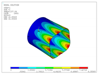 |
| 1 | 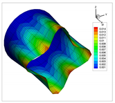 | 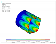 |
| 2 | 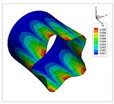 | 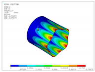 |
| 3 | 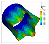 | 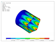 |
| 4 | 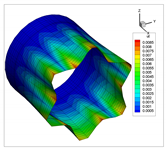 |  |
| 5 |  |  |
| 6 |  | 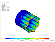 |
| 7 |  | 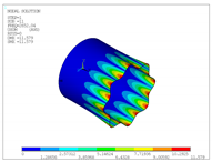 |
| 8 | 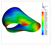 | 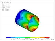 |
| 9 | 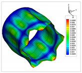 |  |
| 10 | 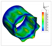 | 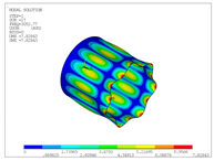 |
| Dimensionless Frequency Parameter | ||||||||||
|---|---|---|---|---|---|---|---|---|---|---|
| 50 | 20 | 10 | 5 | 2.5 | ||||||
| 7-PL | 3D 840,000 | 7-PL | 3D 630,000 | 7-PL | 3D 968,000 | 7-PL | 3D 855,000 | 7-PL | 3D 720,000 | |
| 0.0245 | 0.0284 | 0.0978 | 0.1092 | 0.1846 | 0.1987 | 0.3414 | 0.3487 | 0.6005 | 0.5772 | |
| (13.89) | (10.44) | (7.07) | (2.10) | (4.03) | ||||||
| 0.0695 | 0.0614 | 0.2662 | 0.2374 | 0.4716 | 0.4303 | 0.7441 | 0.7054 | 0.9446 | 0.9289 | |
| (13.14) | (12.16) | (9.60) | (5.49) | (1.69) | ||||||
| 0.0775 | 0.0844 | 0.2973 | 0.3143 | 0.5375 | 0.5534 | 0.9445 | 0.9345 | 1.4447 | 1.4161 | |
| (8.20) | (5.41) | (2.88) | (1.08) | (2.02) | ||||||
| 0.1531 | 0.1559 | 0.5703 | 0.5774 | 1.0087 | 1.0178 | 1.5319 | 1.5357 | 1.4946 | 1.4161 | |
| (1.81) | (1.23) | (0.90) | (0.25) | (5.54) | ||||||
| 0.1685 | 0.1620 | 0.6204 | 0.5883 | 1.0783 | 1.0180 | 1.5688 | 1.5681 | 1.4946 | 1.4783 | |
| (3.99) | (5.47) | (5.92) | (0.05) | (1.11) | ||||||
| 0.2470 | 0.2567 | 0.9001 | 0.9144 | 1.5350 | 1.5361 | 1.7173 | 1.6666 | 1.6346 | 1.6342 | |
| (3.79) | (1.57) | (0.07) | (3.04) | (0.02) | ||||||
| 0.2851 | 0.2704 | 1.0093 | 0.9609 | 1.5511 | 1.5470 | 1.7328 | 1.6714 | 1.9918 | 2.0419 | |
| (5.42) | (5.03) | (0.26) | (3.68) | (2.46) | ||||||
| 0.3566 | 0.3661 | 1.2819 | 1.2872 | 1.5739 | 1.5679 | 1.8992 | 1.8579 | 2.1352 | 2.1141 | |
| (2.57) | (0.41) | (0.38) | (2.22) | (1.00) | ||||||
| 0.3602 | 0.3661 | 1.2880 | 1.2872 | 1.7065 | 1.6401 | 2.0516 | 2.0893 | 2.2496 | 2.2282 | |
| (1.60) | (0.06) | (4.05) | (1.81) | (0.96) | ||||||
| 0.4198 | 0.4043 | 1.4379 | 1.3882 | 1.7295 | 1.7184 | 2.3824 | 2.3743 | 2.3438 | 2.2866 | |
| (3.84) | (3.58) | (0.65) | (0.34) | (2.50) | ||||||
| 0.4928 | 0.4887 | 1.5228 | 1.5236 | 1.8170 | 1.8052 | 2.5573 | 2.4219 | 2.4515 | 2.3295 | |
| (0.83) | (0.05) | (0.65) | (5.59) | (5.24) | ||||||
| 0.5705 | 0.5538 | 1.5488 | 1.5444 | 1.9320 | 1.8895 | 2.5816 | 2.4844 | 3.2142 | 3.1248 | |
| (3.03) | (0.28) | (2.25) | (3.91) | (2.86) | ||||||
| 0.5738 | 0.5538 | 1.6482 | 1.6459 | 2.0753 | 2.0343 | 2.6048 | 2.5075 | 3.2998 | 3.2291 | |
| (3.61) | (0.14) | (2.01) | (3.88) | (2.19) | ||||||
| 0.6450 | 0.6239 | 1.6825 | 1.6728 | 2.2262 | 2.1944 | 2.6870 | 2.6439 | 3.3207 | 3.2354 | |
| (3.39) | (0.58) | (1.45) | (1.63) | (2.63) | ||||||
| 0.6901 | 0.6239 | 1.6855 | 1.6757 | 2.2297 | 2.1946 | 2.7410 | 2.6470 | 3.3207 | 3.2472 | |
| (10.61) | (0.58) | (1.60) | (3.55) | (2.26) | ||||||
| Dimensionless Frequency Parameter | ||||||||||
|---|---|---|---|---|---|---|---|---|---|---|
| 100 | 50 | 20 | 10 | 5 | ||||||
| 7-PL 25 | 3D 847,800 | 7-PL 25 | 3D 840,000 | 7-PL 25 | 3D 628,000 | 7-PL 16 | 3D 642,560 | 7-PL 16 | 3D 628,000 | |
| 0.1815 | 0.1812 | 0.2439 | 0.2429 | 0.3580 | 0.3547 | 0.4823 | 0.4773 | 0.6513 | 0.6324 | |
| (0.15) | (0.44) | (0.94) | (1.05) | (2.99) | ||||||
| 0.1939 | 0.1937 | 0.2677 | 0.2663 | 0.4111 | 0.4096 | 0.5345 | 0.5246 | 0.6896 | 0.6828 | |
| (0.09) | (0.51) | (0.38) | (1.89) | (0.99) | ||||||
| 0.2025 | 0.2022 | 0.2788 | 0.2782 | 0.4215 | 0.4158 | 0.6212 | 0.6192 | 0.8806 | 0.8407 | |
| (0.13) | (0.23) | (1.36) | (0.33) | (4.74) | ||||||
| 0.2306 | 0.2301 | 0.3330 | 0.3314 | 0.5668 | 0.5583 | 0.7428 | 0.7258 | 0.9177 | 0.9244 | |
| (0.19) | (0.50) | (1.52) | (2.35) | (0.72) | ||||||
| 0.2631 | 0.2629 | 0.3825 | 0.3821 | 0.5949 | 0.5943 | 0.9223 | 0.9240 | 1.0719 | 1.0647 | |
| (0.07) | (0.09) | (0.11) | (0.18) | (0.67) | ||||||
| 0.2837 | 0.2807 | 0.4239 | 0.4211 | 0.6679 | 0.6619 | 0.9412 | 0.9281 | 1.2873 | 1.2179 | |
| (1.07) | (0.68) | (0.90) | (1.41) | (5.70) | ||||||
| 0.3131 | 0.3119 | 0.4307 | 0.4279 | 0.6890 | 0.6800 | 0.9657 | 0.9466 | 1.2954 | 1.2514 | |
| (0.39) | (0.64) | (1.32) | (2.02) | (3.52) | ||||||
| 0.3233 | 0.3212 | 0.4496 | 0.4477 | 0.7510 | 0.7471 | 1.0100 | 1.0078 | 1.3159 | 1.2826 | |
| (0.64) | (0.43) | (0.52) | (0.22) | (2.59) | ||||||
| 0.3366 | 0.3357 | 0.4658 | 0.4621 | 0.7619 | 0.7497 | 1.0386 | 1.0187 | 1.3370 | 1.3116 | |
| (0.25) | (0.80) | (1.62) | (1.95) | (1.94) | ||||||
| 0.3516 | 0.3402 | 0.5294 | 0.5271 | 0.8033 | 0.7905 | 1.0462 | 1.0287 | 1.4614 | 1.3950 | |
| (3.33) | (0.44) | (1.62) | (1.71) | (4.76) | ||||||
| 0.3632 | 0.3578 | 0.5353 | 0.5282 | 0.9056 | 0.9028 | 1.1016 | 1.0929 | 1.5314 | 1.5372 | |
| (1.51) | (1.35) | (0.32) | (0.79) | (0.37) | ||||||
| 0.3763 | 0.3762 | 0.5447 | 0.5391 | 0.9234 | 0.9239 | 1.1303 | 1.1019 | 1.5567 | 1.5565 | |
| (0.03) | (1.04) | (0.05) | (2.58) | (0.01) | ||||||
| 0.3974 | 0.3969 | 0.5840 | 0.5838 | 0.9861 | 0.9716 | 1.4065 | 1.3644 | 1.6369 | 1.6246 | |
| (0.13) | (0.02) | (1.49) | (3.09) | (0.76) | ||||||
| 0.4234 | 0.4069 | 0.6313 | 0.6270 | 0.9895 | 0.9717 | 1.4118 | 1.3684 | 1.7816 | 1.6808 | |
| (4.06) | (0.68) | (1.84) | (3.17) | (6.00) | ||||||
| 0.4298 | 0.4069 | 0.6453 | 0.6397 | 0.9895 | 0.9750 | 1.4141 | 1.3684 | 1.7872 | 1.6968 | |
| (5.62) | (0.88) | (1.49) | (3.34) | (5.33) | ||||||
| Dimensionless Frequency Parameter | ||||||||||
|---|---|---|---|---|---|---|---|---|---|---|
| 100 | 50 | 20 | 10 | 5 | ||||||
| 7-PL 25 | 3D 847,800 | 7-PL 25 | 3D 840,000 | 7-PL 25 | 3D 628,000 | 7-PL 16 | 3D 642,560 | 7-PL 16 | 3D 628,000 | |
| 0.0795 | 0.0798 | 0.1112 | 0.1106 | 0.1803 | 0.1765 | 0.2180 | 0.2131 | 0.3171 | 0.3006 | |
| (0.37) | (0.54) | (2.18) | (2.32) | (5.47) | ||||||
| 0.0949 | 0.0960 | 0.1247 | 0.1241 | 0.1804 | 0.1789 | 0.3172 | 0.3068 | 0.3476 | 0.3443 | |
| (1.15) | (0.55) | (0.84) | (3.38) | (0.98) | ||||||
| 0.0967 | 0.0966 | 0.1248 | 0.1241 | 0.2784 | 0.2723 | 0.3296 | 0.3286 | 0.5299 | 0.5334 | |
| (0.07) | (0.57) | (2.21) | (0.31) | (0.66) | ||||||
| 0.1269 | 0.1290 | 0.1663 | 0.1660 | 0.3221 | 0.3217 | 0.5305 | 0.5167 | 0.5843 | 0.5527 | |
| (1.61) | (0.16) | (0.10) | (2.66) | (5.71) | ||||||
| 0.1635 | 0.1634 | 0.1763 | 0.1756 | 0.4212 | 0.4124 | 0.5324 | 0.5167 | 0.7913 | 0.7609 | |
| (0.06) | (0.41) | (2.13) | (3.03) | (3.99) | ||||||
| 0.1679 | 0.1707 | 0.2460 | 0.2450 | 0.4327 | 0.4274 | 0.5324 | 0.5314 | 0.8315 | 0.8288 | |
| (1.61) | (0.40) | (1.24) | (0.20) | (0.32) | ||||||
| 0.2064 | 0.2057 | 0.2493 | 0.2450 | 0.4774 | 0.4690 | 0.6038 | 0.5943 | 0.8529 | 0.8395 | |
| (0.32) | (1.72) | (1.78) | (1.59) | (1.59) | ||||||
| 0.2103 | 0.2096 | 0.2857 | 0.2840 | 0.5210 | 0.5182 | 0.6285 | 0.6125 | 0.9819 | 0.9315 | |
| (0.34) | (0.62) | (0.52) | (2.61) | (5.40) | ||||||
| 0.2176 | 0.2190 | 0.2967 | 0.2940 | 0.5306 | 0.5309 | 0.7838 | 0.7790 | 0.9848 | 0.9516 | |
| (0.62) | (0.90) | (0.04) | (0.62) | (3.50) | ||||||
| 0.2421 | 0.2416 | 0.3182 | 0.3181 | 0.5957 | 0.5826 | 0.8079 | 0.7851 | 1.0035 | 0.9783 | |
| (0.22) | (0.04) | (2.24) | (2.90) | (2.58) | ||||||
| 0.2438 | 0.2426 | 0.3397 | 0.3275 | 0.5999 | 0.5826 | 0.8160 | 0.8030 | 1.0035 | 1.0102 | |
| (0.49) | (3.73) | (2.96) | (1.62) | (0.66) | ||||||
| 0.2789 | 0.2737 | 0.3442 | 0.3432 | 0.6187 | 0.6068 | 0.8266 | 0.8030 | 1.0174 | 1.0102 | |
| (1.93) | (0.31) | (1.97) | (2.94) | (0.71) | ||||||
| 0.2976 | 0.2936 | 0.3586 | 0.3547 | 0.7530 | 0.7517 | 0.8266 | 0.8148 | 1.0174 | 1.1043 | |
| (1.38) | (1.09) | (0.17) | (1.45) | (7.87) | ||||||
| 0.3170 | 0.3169 | 0.3618 | 0.3547 | 0.7619 | 0.7530 | 0.9636 | 0.9608 | 1.1225 | 1.3225 | |
| (0.02) | (2.00) | (1.18) | (0.29) | (15.12) | ||||||
| 0.3266 | 0.3263 | 0.4475 | 0.4222 | 0.7721 | 0.7599 | 0.9875 | 0.9866 | 1.3384 | 1.3225 | |
| (0.10) | (5.98) | (1.62) | (0.09) | (1.20) | ||||||
| Dimensionless Frequency Parameter | ||||||||||
|---|---|---|---|---|---|---|---|---|---|---|
| 100 | 50 | 20 | 10 | 5 | ||||||
| 7-PL 16 | 3D 645,344 | 7-PL 16 | 3D 703,360 | 7-PL 16 | 3D 603,680 | 7-PL 16 | 3D 639,576 | 7-PL 16 | 3D 743,400 | |
| 0.0170 | 0.0164 | 0.0240 | 0.0222 | 0.0464 | 0.0445 | 0.0136 | 0.0131 | 0.0186 | 0.0169 | |
| (4.18) | (8.17) | (4.34) | (4.37) | (10.02) | ||||||
| 0.0296 | 0.0291 | 0.0416 | 0.0411 | 0.0496 | 0.0457 | 0.0414 | 0.0375 | 0.0530 | 0.0520 | |
| (1.79) | (1.34) | (8.51) | (10.30) | (1.94) | ||||||
| 0.0527 | 0.0526 | 0.0742 | 0.0721 | 0.1381 | 0.1344 | 0.0600 | 0.0588 | 0.0864 | 0.0809 | |
| (0.35) | (2.97) | (2.73) | (2.04) | (6.79) | ||||||
| 0.0580 | 0.0575 | 0.0832 | 0.0820 | 0.1721 | 0.1663 | 0.0670 | 0.0661 | 0.0901 | 0.0834 | |
| (0.95) | (1.40) | (3.44) | (1.41) | (8.04) | ||||||
| 0.0638 | 0.0633 | 0.0988 | 0.0969 | 0.1855 | 0.1834 | 0.1025 | 0.0993 | 0.1877 | 0.1802 | |
| (0.75) | (1.89) | (1.18) | (3.26) | (4.15) | ||||||
| 0.0883 | 0.0888 | 0.1646 | 0.1626 | 0.1939 | 0.1937 | 0.1636 | 0.1624 | 0.2112 | 0.2074 | |
| (0.53) | (1.23) | (0.08) | (0.74) | (1.85) | ||||||
| 0.1064 | 0.1060 | 0.1709 | 0.1676 | 0.2830 | 0.2789 | 0.1791 | 0.1761 | 0.2493 | 0.2502 | |
| (0.45) | (2.01) | (1.44) | (1.75) | (0.36) | ||||||
| 0.1116 | 0.1111 | 0.1711 | 0.1697 | 0.2977 | 0.2933 | 0.2427 | 0.2428 | 0.3068 | 0.3066 | |
| (0.42) | (0.79) | (1.51) | (0.06) | (0.05) | ||||||
| 0.1425 | 0.1423 | 0.1946 | 0.1943 | 0.3336 | 0.3295 | 0.2751 | 0.2714 | 0.3272 | 0.3179 | |
| (0.16) | (0.17) | (1.24) | (1.36) | (2.91) | ||||||
| 0.1621 | 0.1636 | 0.2266 | 0.2260 | 0.4195 | 0.4119 | 0.2804 | 0.2781 | 0.3761 | 0.3702 | |
| (0.90) | (0.28) | (1.85) | (0.82) | (1.60) | ||||||
| 0.1644 | 0.1640 | 0.2446 | 0.2412 | 0.4703 | 0.4642 | 0.2941 | 0.2884 | 0.4884 | 0.4765 | |
| (0.26) | (1.41) | (1.32) | (1.95) | (2.51) | ||||||
| 0.1651 | 0.1654 | 0.2535 | 0.2512 | 0.4984 | 0.4924 | 0.3065 | 0.3064 | 0.5238 | 0.5262 | |
| (0.20) | (0.92) | (1.22) | (0.03) | (0.45) | ||||||
| 0.1933 | 0.1931 | 0.2626 | 0.2602 | 0.5387 | 0.5348 | 0.3834 | 0.3772 | 0.5518 | 0.5347 | |
| (0.06) | (0.93) | (0.73) | (1.64) | (3.20) | ||||||
| 0.2118 | 0.2120 | 0.3215 | 0.3170 | 0.5684 | 0.5610 | 0.3908 | 0.3859 | 0.5821 | 0.5688 | |
| (0.10) | (1.40) | (1.33) | (1.26) | (2.33) | ||||||
| 0.2252 | 0.2254 | 0.3467 | 0.3431 | 0.6135 | 0.6133 | 0.4133 | 0.4099 | 0.6773 | 0.6601 | |
| (0.08) | (1.05) | (0.03) | (0.84) | (2.59) | ||||||
| Dimensionless Frequency Parameter | ||||||||||||
|---|---|---|---|---|---|---|---|---|---|---|---|---|
| 1 | 2 | 3 | 4 | 5 | 10 | |||||||
| 7-PL 16 | 3D 642,560 | 7-PL 16 | 3D 862,400 | 7-PL 16 | 3D 812,160 | 7-PL 16 | 3D 832,480 | 7-PL 16 | 3D 785,000 | 7-PL 16 | 3D 539,000 | |
| 0.3450 | 0.3122 | 0.1015 | 0.0969 | 0.0467 | 0.0447 | 0.0266 | 0.0254 | 0.0171 | 0.0164 | 0.00429 | 0.00411 | |
| (10.49) | (4.70) | (4.46) | (4.40) | (4.37) | (4.38) | |||||||
| 0.3508 | 0.3232 | 0.1391 | 0.1241 | 0.0861 | 0.0768 | 0.0619 | 0.0553 | 0.0476 | 0.0429 | 0.01660 | 0.01620 | |
| (8.55) | (12.13) | (12.09) | (11.80) | (11.06) | (2.46) | |||||||
| 0.5966 | 0.5489 | 0.3330 | 0.3326 | 0.1746 | 0.1741 | 0.1069 | 0.1063 | 0.0727 | 0.0717 | 0.02184 | 0.02155 | |
| (8.68) | (0.12) | (0.25) | (0.60) | (1.32) | (1.36) | |||||||
| 0.8582 | 0.8559 | 0.3704 | 0.3543 | 0.2063 | 0.2028 | 0.1249 | 0.1230 | 0.0829 | 0.0818 | 0.02672 | 0.02430 | |
| (0.27) | (4.54) | (1.75) | (1.53) | (1.44) | (9.96) | |||||||
| 1.0280 | 0.9713 | 0.3877 | 0.3718 | 0.2206 | 0.2128 | 0.1530 | 0.1479 | 0.1170 | 0.1133 | 0.05322 | 0.05164 | |
| (5.84) | (4.27) | (3.66) | (3.42) | (3.30) | (3.05) | |||||||
| 1.1272 | 1.0630 | 0.4021 | 0.3886 | 0.3287 | 0.3172 | 0.2804 | 0.2750 | 0.1988 | 0.1972 | 0.05630 | 0.05595 | |
| (6.04) | (3.49) | (3.63) | (1.97) | (0.79) | (0.63) | |||||||
| 1.1641 | 1.0938 | 0.6800 | 0.6597 | 0.4243 | 0.4149 | 0.2858 | 0.2831 | 0.2074 | 0.2037 | 0.08887 | 0.08778 | |
| (6.43) | (3.07) | (2.28) | (0.96) | (1.81) | (1.25) | |||||||
| 1.4464 | 1.3788 | 0.7830 | 0.7599 | 0.4459 | 0.4391 | 0.3097 | 0.3012 | 0.2880 | 0.2882 | 0.09391 | 0.09356 | |
| (4.90) | (3.04) | (1.54) | (2.82) | (0.07) | (0.37) | |||||||
| 1.7101 | 1.6620 | 0.8028 | 0.7825 | 0.4976 | 0.4860 | 0.3962 | 0.3965 | 0.2959 | 0.2894 | 0.10435 | 0.10389 | |
| (2.90) | (2.59) | (2.39) | (0.09) | (2.24) | (0.44) | |||||||
| 1.7427 | 1.7084 | 0.8611 | 0.8393 | 0.5732 | 0.5730 | 0.4272 | 0.4209 | 0.3227 | 0.3181 | 0.13021 | 0.12872 | |
| (2.01) | (2.59) | (0.05) | (1.50) | (1.43) | (1.16) | |||||||
| 1.8404 | 1.8158 | 0.8677 | 0.8604 | 0.5771 | 0.5777 | 0.4322 | 0.4300 | 0.3383 | 0.3355 | 0.16278 | 0.16216 | |
| (1.36) | (0.86) | (0.10) | (0.51) | (0.84) | (0.38) | |||||||
| 1.8993 | 1.8412 | 0.9233 | 0.9239 | 0.6919 | 0.6782 | 0.4472 | 0.4400 | 0.3436 | 0.3434 | 0.17148 | 0.17143 | |
| (3.16) | (0.07) | (2.03) | (1.63) | (0.05) | (0.03) | |||||||
| 2.0950 | 2.0922 | 1.1355 | 1.1057 | 0.7089 | 0.6961 | 0.4708 | 0.4654 | 0.3972 | 0.3902 | 0.17619 | 0.17446 | |
| (0.13) | (2.70) | (1.82) | (1.16) | (1.77) | (0.99) | |||||||
| 2.3301 | 2.2226 | 1.2046 | 1.1702 | 0.7404 | 0.7262 | 0.5751 | 0.5645 | 0.4625 | 0.4563 | 0.21804 | 0.21820 | |
| (4.84) | (2.94) | (1.96) | (1.87) | (1.35) | (0.08) | |||||||
| 2.3632 | 2.2491 | 1.3029 | 1.2680 | 0.8067 | 0.7868 | 0.6493 | 0.6391 | 0.4859 | 0.4813 | 0.22795 | 0.22612 | |
| (5.08) | (2.75) | (2.54) | (1.61) | (0.94) | (0.81) | |||||||
| Vibration Mode | Formulation | |
|---|---|---|
| 7-PL | 3D | |
| 1 | 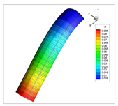 | 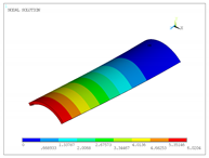 |
| 2 | 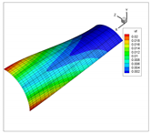 | 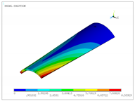 |
| 3 | 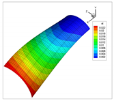 | 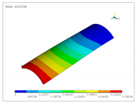 |
| 4 | 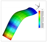 | 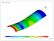 |
| 5 | 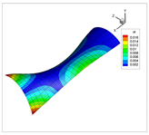 | 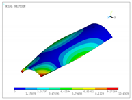 |
| 6 |  |  |
| 7 | 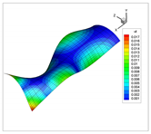 |  |
| 8 | 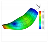 | 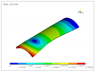 |
| 9 | 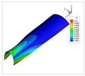 |  |
| 10 | 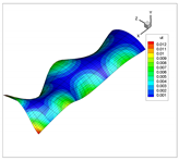 | 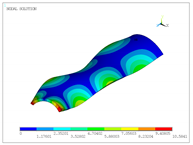 |
© 2020 by the authors. Licensee MDPI, Basel, Switzerland. This article is an open access article distributed under the terms and conditions of the Creative Commons Attribution (CC BY) license (http://creativecommons.org/licenses/by/4.0/).
Share and Cite
Valencia Murillo, C.; Gutierrez Rivera, M.; Reddy, J.N. Linear Vibration Analysis of Shells Using a Seven-Parameter Spectral/hp Finite Element Model. Appl. Sci. 2020, 10, 5102. https://doi.org/10.3390/app10155102
Valencia Murillo C, Gutierrez Rivera M, Reddy JN. Linear Vibration Analysis of Shells Using a Seven-Parameter Spectral/hp Finite Element Model. Applied Sciences. 2020; 10(15):5102. https://doi.org/10.3390/app10155102
Chicago/Turabian StyleValencia Murillo, Carlos, Miguel Gutierrez Rivera, and Junuthula N. Reddy. 2020. "Linear Vibration Analysis of Shells Using a Seven-Parameter Spectral/hp Finite Element Model" Applied Sciences 10, no. 15: 5102. https://doi.org/10.3390/app10155102
APA StyleValencia Murillo, C., Gutierrez Rivera, M., & Reddy, J. N. (2020). Linear Vibration Analysis of Shells Using a Seven-Parameter Spectral/hp Finite Element Model. Applied Sciences, 10(15), 5102. https://doi.org/10.3390/app10155102


