Article

Optical Design of Compact Space Autonomous Docking Instrument with CMOS Image Sensor and All Radiation Resistant Lens Elements

1
National Space Organization, National Applied Research Laboratories, 8F, 9 Prosperity 1st Road, Hsinchu Science Park, Hsinchu 300091, Taiwan
2
Department of Photonics, Institute of Electro–Optical Engineering, College of Electrical and Computer Engineering, National Chiao Tung University, Hsinchu 300093, Taiwan
*
Authors to whom correspondence should be addressed.
Appl. Sci. 2020, 10(15), 5302; https://doi.org/10.3390/app10155302
Submission received: 20 June 2020 / Revised: 24 July 2020 / Accepted: 28 July 2020 / Published: 31 July 2020
(This article belongs to the Special Issue Joint Special Issue With OPTIC 2019)

Abstract

:
Built-in autonomous stereo vision devices play a critical role in the autonomous docking instruments of space vehicles. Traditional stereo cameras for space autonomous docking use charge-coupled device (CCD) image sensors, and it is difficult for the overall size to be reduced due to the size of the CCD. In addition, only the few outermost elements of the camera lens use radiation-resistant optical glass material. In this paper, a complementary metal–oxide semiconductor (CMOS) device is used as the image sensor, and radiation-resistant optical glass material is introduced to all lens elements in order to make a compact and highly reliable space grade instrument. Despite the limited available material, a fixed focus module with 7 lens elements and overall length of 42 mm has been achieved, while meeting all the required performance demands for the final vision-guided docking process.

1. Introduction

In order to realize the objectives of continuous return to the lunar surface, work in low-Earth on-orbit, and paving the way for the deployment of missions to the Moon and Mars, a new item called “Autonomous Systems” has been revealed in the NASA technical classification published in 2020 [1]. Built-in autonomous stereo vision devices play a vital role in position sensing and perception or pose estimation to facilitate the autonomous docking of multiple daughter–mother space vehicles, so as to expand their versatile applications in planetary science exploration. The final docking phase is the most challenging, particularly for re-docking the daughter space vehicles to the mother space vehicles [2].
In the final docking stage, fiducial targets are employed for the algorithms of autonomous docking navigation to improve the reliability of lateral control; within the operational range of 10 m and ±30° field of view (FOV), the required accuracy is 1 cm [3]. The space docking cameras play the chief role of image capturing in autonomous stereo vision-guided docking devices. The captured image will be integrated into the algorithm for the autonomous docking system [3,4,5]. Currently, those space docking cameras are often equipped with charge-coupled device (CCD) image sensors [3,6]. Due to the technical issue in further reducing the size of the CCD device, it, in turn, becomes difficult to make the overall size of the camera more compact. Complementary metal–oxide semiconductor (CMOS) image sensors are widely applied in image capturing devices due to the features of small package size, low power consumption, and high readout speed. Using CMOS to replace CCD would be the most effective solution to reduce the form factor of the camera [7,8,9]. The higher readout speed of the CMOS device is also favorable for the autonomous docking algorithm, which takes time to calculate the accurate position in a dynamic situation. In addition, current space docking cameras employ radiation resistant material only for the outermost few lens elements. The lens elements without radiation resistance could degrade quickly, and, in turn, influence the optical performance of the camera. The solution would be introducing radiation resistant material for all lens elements to increase the radiation resistance of the overall system and make a space grade imager instrument.
This paper presents the optical design process of a compact radiation-resistant camera lens module for space autonomous docking instruments equipped with the MT9P031 CMOS image sensor (CIS). The design result of this camera lens module will be introduced to the National Space Organization (NSPO) pilot program for space exploration application. Section 2 derives the optical specification of the camera based on the requirements of the autonomous docking operation, and gives a review on the available radiation resistant material. Section 3 describes the optimization and simulation of the camera module, with the radiation resistant material meeting all the required specifications. Finally, Section 4 gives the conclusion.

2. Specification of Camera Module and Radiation Resistant Material

During the final docking phase, the operation takes place at a distance range between at least 1 and 10 m and a FOV of ±30° is required [3], which is used as the base for defining the major optical performance of the camera. The image sensor is the ON Semiconductor® Aptina™ MT9P031 CIS, and its major parameters are listed in Table 1 [10].
A fixed focus lens, which does not contain moving parts, and is thus less sensitive to launching in an on-orbit environment, is preferable for the docking camera. With the fixed focus and small-aperture, a pan-focus lens is capable of giving deep depth of field (DOF) by setting the object distance at a hyperfocal distance [11]. The aperture can then be calculated with this object distance or hyperfocal distance. The procedure for evaluating hyperfocal distance/object distance and f-number are listed in Equations (1)–(6) [11].
H = f 2 F N · C + f   ,
N L = S · ( H f ) H + S ( 2 · f )     ,
F L = S · ( H f ) H S   ;
N L = H / 2 ,
  F L   ( infinity ) ; if     1 / F L 0     for   F L > 20   m
S = f · ( f + F N · C ) F N · C     ,
or
F N = f 2 C · ( S f )     ,
where
  • H : Hyperfocal distance (mm);
  • f : Effective focal length (EFL);
  • F N :  f–number;
  • C : Circle of confusion (CoC);
  • N L :  Near focus limit (mm);
  • S : Object distance (mm);
  • F L : Far focus limit (mm);
in the hyperfocal condition:
The operation range condition required FOV around ±30° [3]. In addition, the image height should be larger than the active imager size in diagonal (7.13 mm). Assume the image height given is 3% larger than the active imager size, i.e., estimated image height h i ≈ 7.4 mm. The estimated EFL obtained is:
EFL = h i 2 t a n ( F O V ) ;   f   6.4   ( mm ) ,
In the CoC estimation, common practice was a realistic blur spot diameter of 0.2 mm (5 lp/mm) at a distance of 25 cm in print diagonal (218.44 mm) for print CoC of 5 (inch) × 7 (inch). Given the MT9P031 CIS active imager size in sensor diagonal was 7.13 mm. The estimated MT9P031 CIS’s CoC obtained:
CoC = 1/[(5 lp/mm) × (print diagonal/sensor diagonal)]; C ≈ 0.0057 (mm),
The following assumption was made:
S = H ≈ 900 mm for a reasonable hyperfocal distance in Equation (5) or Equation (6),
thus
F N ≈ 8 has been obtained from Equation (6) for targeting specification of system f–number,
Based on the evaluation described above, the optical specification of the camera module is summarized in Table 2.
The camera will be operated in a harsh radiation environment, which will include solar radiation, galactic cosmic rays, heavy ions, electrons and protons, therefore, they must be tolerant toward these radiation effects.
Figure 1 shows a collection of radiation resistant optical glass materials for the design of compact radiation resistant lenses, as shown in the glass codes and glass types that are shown side by side in the glass chart to serve as a reference in the design process [12,13].
In contrast to BK7G18 and K5G20, some glasses (such as SF6G05 and F2G12) are subjected to a transmittance loss of approximately 0.25% at the range of wavelength longer than 500 nm after they absorb more than 1.0 × 10+6 Gy radiation dose of gamma radiation [12].

3. Optical Design and Simulation

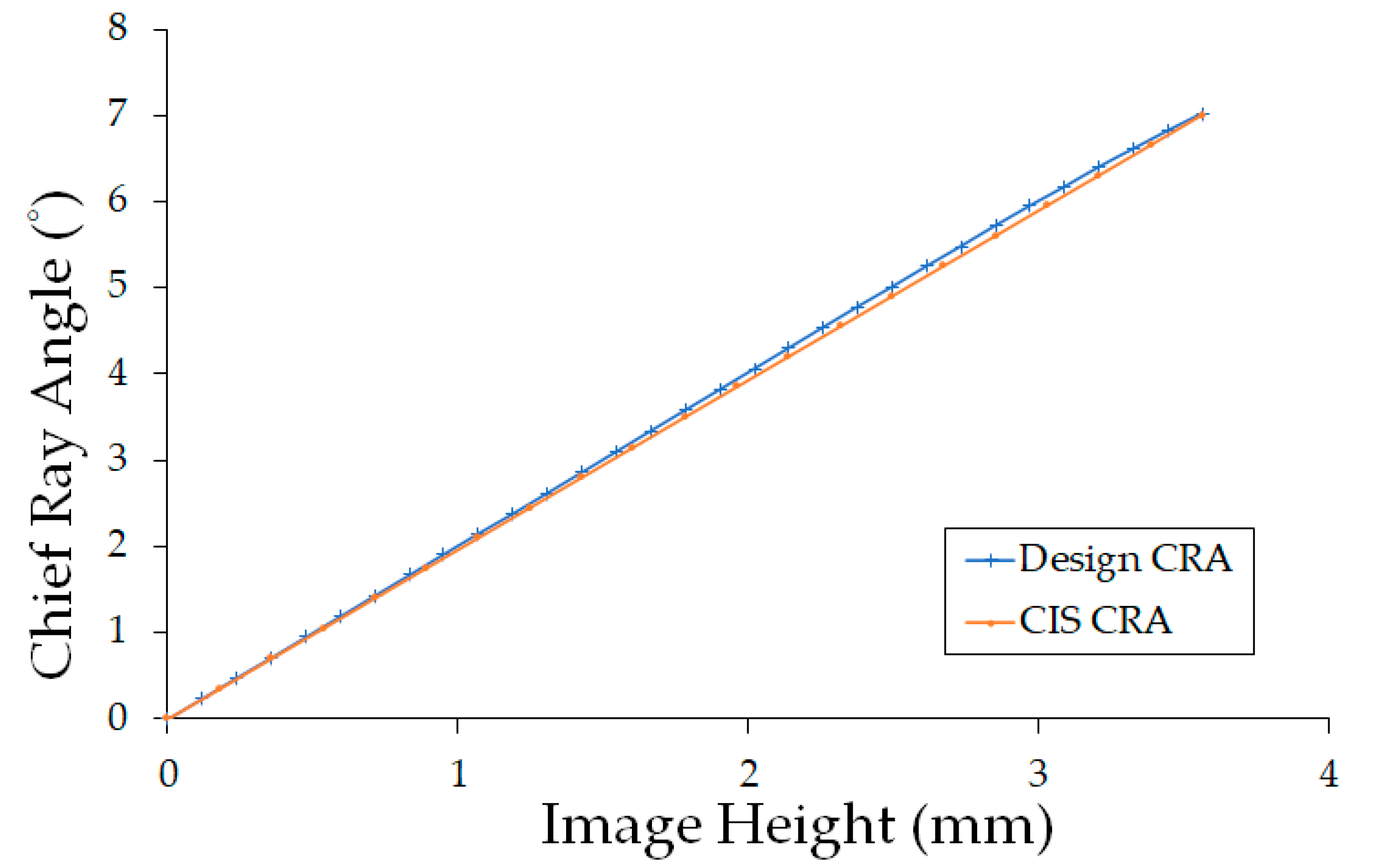
Optical design program Synopsys CODE V® [14] is used for optimization and simulation. In making the optical layout, chief ray angle (CRA), as shown in Table 2, is a major concern. CRA is associated with the photometric efficiency of CIS detectors. The CRA of MT9P031 CIS is specified to be 7° @ Max. image height h i = 7.13 mm. Therefore, the position of the exit pupil must be controlled to be located around h i / ( 2 t a n ( 7 ) )   ≈ 29 mm in front of the image plane.
As shown in Figure 2, the final lens module is comprised of 7 elements and 3 different radiation resistant optical glasses, LF5G15, LAK9G15, and SF6G05; the total length of the lens is 42 mm, and the outer diameter is less than 20 mm.
Table 3 lists the optical parameters of the lens module. The air thickness space between lens L7 and CIS’s cover glass was approximately 3.5 mm, which will be used for compensation and focus tuning to achieve a deeper depth of field under hyperfocal conditions [11].
Figure 3 shows the CRA curve of the designed lens versus the specified CRA of MT9P031 CIS. These two curves match almost perfectly with a maximum deviation below 0.15°.
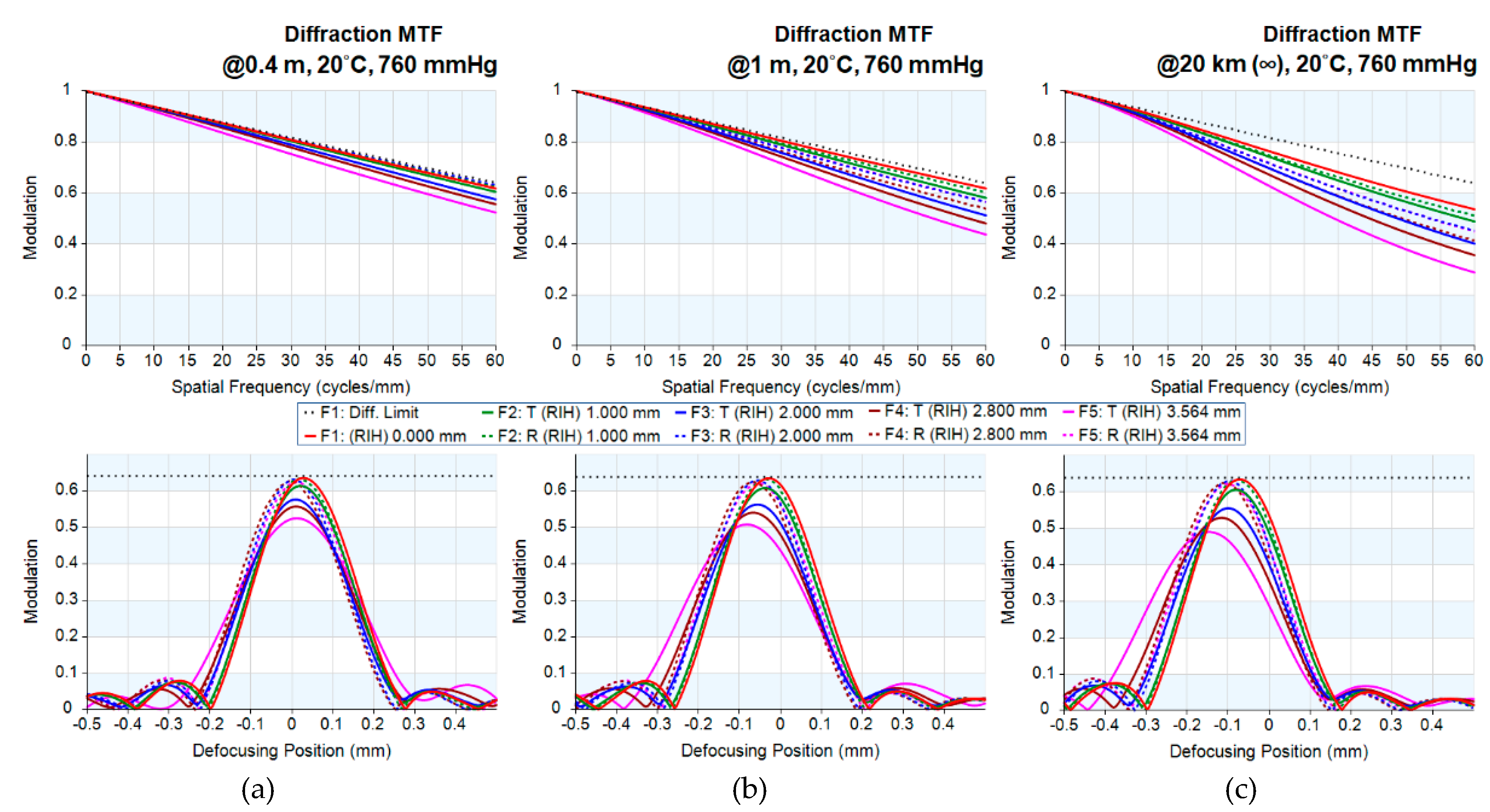
The thermal effect of the extreme temperatures in space could cause serious deviation of the optical path length. The evaluation of Modulation Transfer Function (MTF) should take the thermal effect into consideration. The dimension of both mechanical mounting material and optical material will be affected by the temperature which can be evaluated through the coefficient of thermal expansion. The refractive index of optical material is also temperature-dependent. The material of lens barrel is assumed to be aluminum.
Figure 4 shows the MTF and through-focus performance values across the entire field (i.e., F1: on axis, F2: image height = 1 mm, F3: image height = 2 mm, F4: image height = 2.8 mm, and F5: full image height) of the lens at object distances of 0.4 m (Figure 4a), 1 m (Figure 4b), and 20 km (Figure 4c), under Normal Temperature and Pressure (NTP; 20 °C, 760 mm–Hg) conditions. As can be seen in Figure 4c, a favorable allowance of focal shift (approximately −0.1 mm) is observed when the object distance moved towards infinity.
Figure 5 shows the MTF and the through-focus MTF performance value across the entire field (i.e., F1: on axis, F2: image height = 1 mm, F3: image height = 2 mm, F4: image height = 2.8 mm, and F5: full image height) of the lens at an object distance of around 1 m at the temperatures of −100 °C (Figure 5a), NTP conditions (Figure 5b) and 115 °C (Figure 5c). As can be seen in Figure 5c, a favorable allowance of focal shift (approximately −0.1 mm) is observed when the temperature rises to 115 °C.
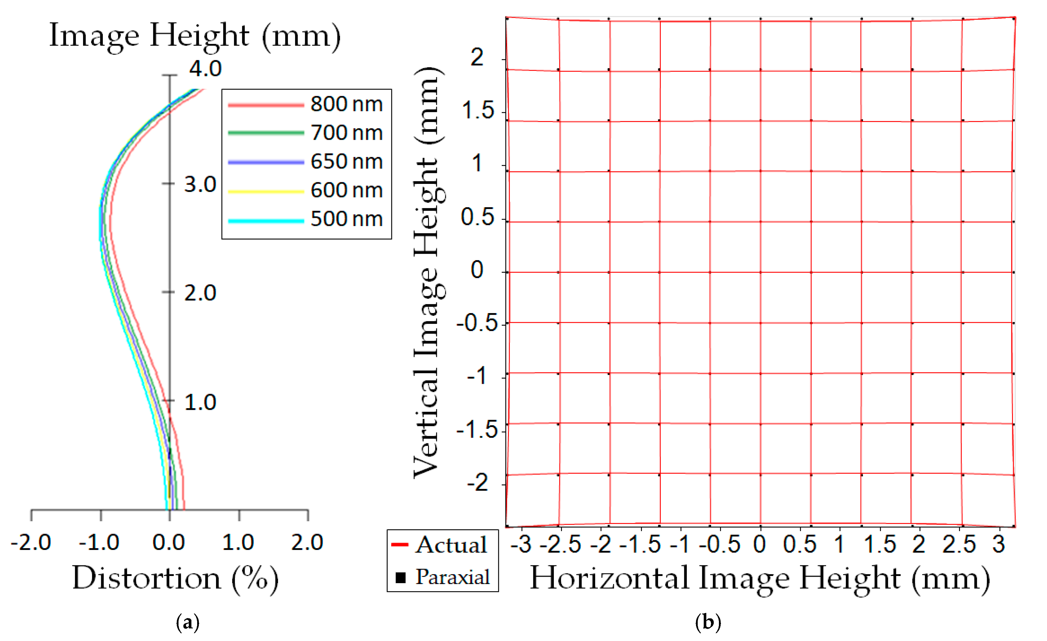
Figure 6 shows the optical distortion curve of the system with wavelengths ranging from 500 to 800 nm and the distortion grid of entire image fields. The absolute values of mustache type distortion of the lens system are less than 1% throughout entire image fields.

4. Conclusions

Optical analysis shows that the design results meet all the required optical specifications of the camera dedicated for autonomous docking, especially at the final stage, where the approaching distance is between 0.5 and 20 m, with all lens elements exploiting radiation resistant material. By introducing CIS as the image sensor, the overall length of the docking camera module was reduced to 42 mm, nearly half of the side length of the existing smallest space vehicles for the potential application in the CubeSat (e.g., 1U–CubeSat), the shortest of the same kind in exist.

Author Contributions

Conceptualization, C.-H.C. and S.-F.L.; methodology, S.-F.L.; software, S.-F.L.; validation, S.-F.L.; formal analysis, S.-F.L.; investigation, S.-F.L.; resources, S.-F.L.; data curation, S.-F.L.; writing—original draft preparation, S.-F.L.; writing—review and editing, C.-H.C. and S.-F.L.; visualization, C.-H.C. and S.-F.L.; supervision, C.-H.C. and S.-F.L. All authors have read and agreed to the published version of the manuscript.

Funding

This research received no external funding.

Acknowledgments

The authors gratefully acknowledge the support of National Space Organization for the support to conduct the research of the results in this study.

Conflicts of Interest

The authors declare no conflict of interest.

References

  1. Miranda, D.J. TX10: Autonomous Systems. In 2020 NASA Technology Taxonomy; NASA: Washington, DC, USA, 2020; pp. 115–117. [Google Scholar]
  2. Bandyopadhyay, S.; Foust, R.; Subramanian, G.P.; Chung, S.-J.; Hadaegh, F.Y. Review of formation flying and constellation missions using nanosatellites. J. Spacecr. Rockets 2016, 53, 567–578. [Google Scholar] [CrossRef] [Green Version]
  3. Fehse, W. Sensors for rendezvous navigation. In Automated Rendezvous and Docking of Spacecraft, 1st ed.; Rycroft, M.J., Shyy, W., Eds.; Cambridge University Press: New York, NY, USA, 2003; pp. 267–279. [Google Scholar]
  4. Tsai, D.; Nesnas, I.A.D.; Zarzhitsky, D. Autonomous vision-based tethered-assisted rover docking. In Proceedings of the 2013 IEEE/RSJ International Conference on Intelligent Robots and Systems, Tokyo, Japan, 3–7 November 2013; IEEE: Tokyo, Japan, 2013; pp. 2834–2841. [Google Scholar]
  5. Pirat, C.; Ankersen, F.; Walker, R.; Gass, V. Vision based navigation for autonomous cooperative docking of CubeSats. Acta Astronaut. 2018, 146, 418–434. [Google Scholar] [CrossRef]
  6. Smith, G.H.; Hagerott, E.C.; Scherr, L.M.; Herkenhoff, K.E.; Bell, J.F., III. Optical designs for the Mars’ 03 rover cameras. In Current Developments in Lens Design and Optical Engineering II, Proceedings of the SPIE, International Symposium on Optical Science and Technology, San Diego, CA, USA, 5 December 2001; International Society for Optics and Photonics: San Diego, CA, USA, 2001; Volume 4441, pp. 118–131. [Google Scholar]
  7. IMEC Report. GSTP/ASCMSA/Integrated Radiation—Tolerant Imaging System—Identification of CMOS Imager Applications in Space; P60280–MS–RP–001, Issue 0.1; IMEC: Leuven, Belgium, 1997; pp. 5–15. [Google Scholar]
  8. Rizzolo, S.; Goiffon, V.; Corbière, F.; Molina, R.; Chabane, A.; Girard, S.; Paillet, P.; Magnan, P.; Boukenter, A.; Allanche, T.; et al. Radiation hardness comparison of CMOS image sensor technologies at high total ionizing dose levels. IEEE Trans. Nucl. Sci. 2018, 66, 111–119. [Google Scholar] [CrossRef]
  9. Huffman, W.; Thompson, D.R.; Bue, B.; Castillo–Rogez, J.; Boland, J. Autonomous Onboard Point Source Detection by Small Exploration Spacecraft. Publ. Astron. Soc. Pac. 2015, 127, 1279–1291. [Google Scholar] [CrossRef] [Green Version]
  10. Imaging, A. 1/2.5–Inch 5Mp CMOS Digital Image Sensor; Rev, F., Ed.; Aptina Imaging: Singapore, 2005; pp. 1–46. [Google Scholar]
  11. Ray, S.F. Applied Photographic Optics: Imaging Systems for Photography, Film, and Video, 1st ed.; Focal press: London, UK, 1988; pp. 164–211. [Google Scholar]
  12. SCHOTT Radiation Resistant Optical Glasses. Technical Documents—TIE’s. Available online: https://www.us.schott.com/advanced_optics/english/knowledge-center/technical-articles-and-tools/tie.html (accessed on 2 May 2020).
  13. OHARA Optical Glass Information. Optical Glass Cross Reference Sheet. Available online: https://www.oharacorp.com/pdf/cross-ref-2020-01-opt.pdf (accessed on 2 May 2020).
  14. Synopsys, in CODE V Documentation Library; CODE V® Synopsys: Mountain View, CA, USA, 2019.
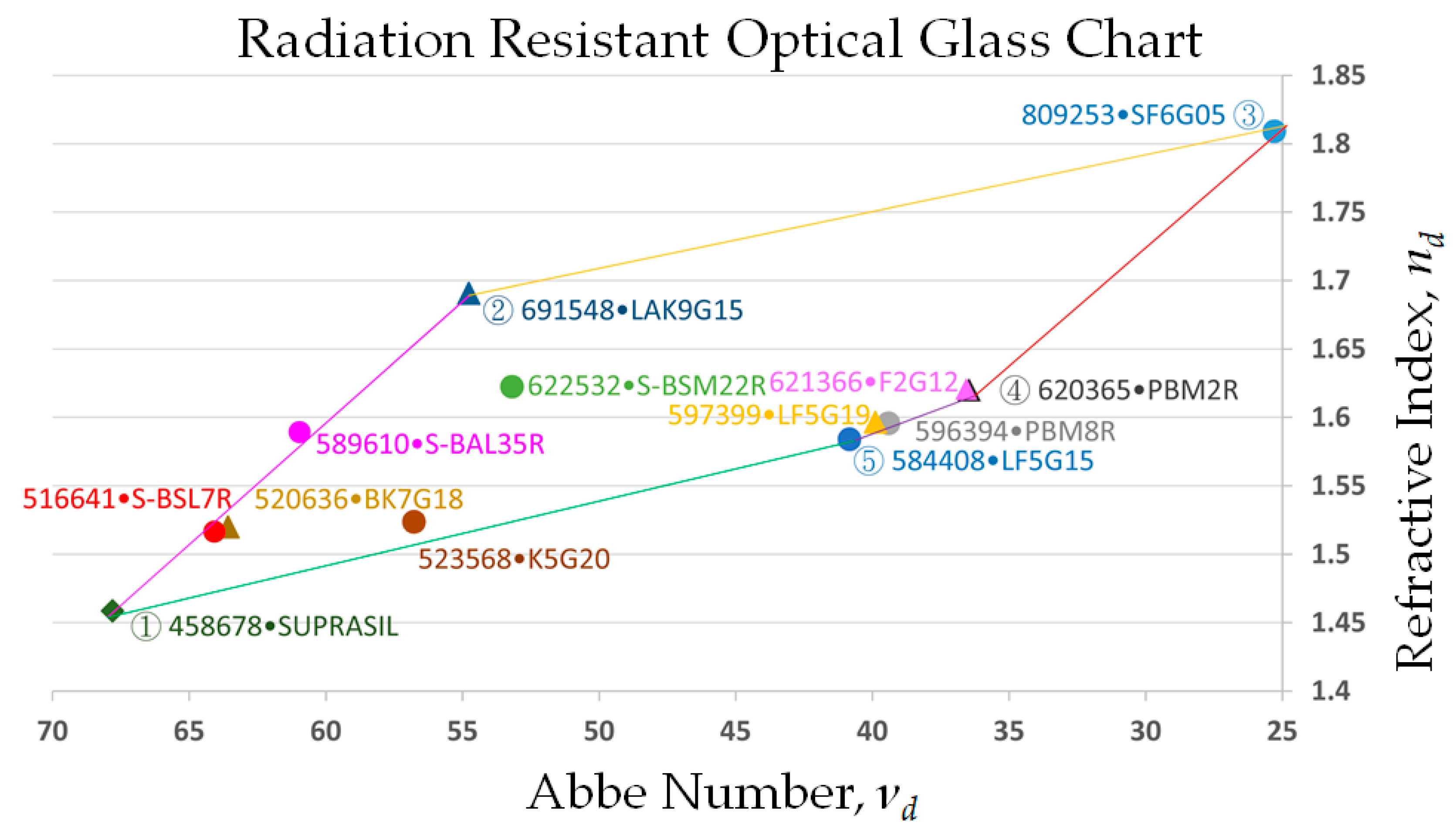
Figure 1. Radiation resistant optical glass materials.
Applsci 10 05302 g001
Figure 2. Optical layout of the docking camera lens.
Applsci 10 05302 g002
Figure 3. Chief ray angle (CRA) curve of the designed value and specified value of MT9P031 CIS.
Applsci 10 05302 g003
Figure 4. MTF and the through-focus MTF of the lenses at object distances of (a) 0.4 m, (b) 1 m, and (c) infinity (20 km) under NTP conditions.
Applsci 10 05302 g004
Figure 5. MTF and through-focus MTF of the lens at an object distance of 1 m in space ambient temperatures of (a) −100 °C, 115 °C (c), and under NTP conditions (b).
Applsci 10 05302 g005
Figure 6. (a) Distortion curve and (b) distortion grid of the lens module.
Applsci 10 05302 g006
Table 1. Major parameters of ON Semiconductor® Aptina™ MT9P031 CIS.
ParametersValue
Optical Format1/2.5 inch (4:3)
Active Pixels2592H × 1944V (640 × 480, with binning) *
Pixel Size2.2 μm × 2.2 μm
Active Imager Size5.70 mm(H) × 4.28 mm(V), 7.13 mm diagonal
Chief Ray Angle (CRA)≦7° Max.
Operating Temperature−30 °C to +70 °C
* Pixel binning for sub-pixel resolution [3,5].
Table 2. Specifications of the space autonomous docking camera.
PropertiesSpecification
f–number, F N 8
EFL, f (mm) 6.4
Wavelengths Range (nm)500–800
As–Built MTF * @ 57 lp/mm (640 × 480, with binning) **0.25
Focal Range, N L F L (m)<0.5–infinity
Hyperfocal Distance, H (mm) 900
Image Height, h i (mm)>7.13 + 10%
FOV ± 30°
Max. Chief Ray Angle (CRA)7° ± 1°
Optical Distortion ( A b s . |   ± %   | )<2
Relative Illumination (%)>70
Overall Length (mm)<50
Operating Temperature (°C)−30–+70
* Modulation Transfer Function (MTF) ** Pixel binning for sub-pixel resolution [3,5].
Table 3. Lens data of the docking camera lens.
Surface NumberSurface NameSurface TypeY RadiusThicknessGlass
Objective SphereInfinity (N)400–∞
1L1Sphere38.2340003.000000LF5G15_SCHOTT
2 Sphere5.9910003.150000
3L2Sphere−31.1150008.570000LAK9G15_SCHOTT
4 Sphere−9.8170005.850000
5L3Sphere−4.8310002.310000LF5G15_SCHOTT
6 Sphere−7.0840000.500000
7Aperture StopSphereInfinity (N)0.500000
8L4Sphere50.5010002.080000LAK9G15_SCHOTT
9 Sphere−11.7440003.290000
10L5Sphere10.6930002.610000LAK9G15_SCHOTT
11 Sphere−5.9620000.570000
12L6Sphere−4.7300001.000000SF6G05_SCHOTT
13 Sphere6.2570001.190000
14L7Sphere11.8930003.350000LF5G15_SCHOTT
15 Sphere−7.3850003.503444
16Cover GlassSphereInfinity (N)0.400000D263T_SCHOTT
17 SphereInfinity (N)0.125000
Image SphereInfinity (N)0