Article

A Method for Reducing of the Overall Torsion for Reinforced Concrete Multi-Storey Irregular Structures

by
Marius Florin Botis
1 and
Camelia Cerbu
2,*
1
No. 29, B-dul Eroilor, Department of Civil Engineering, Faculty of Civil Engineering, Transilvania University of Brasov, 500036 Brasov, Romania
2
No. 29, B-dul Eroilor, Department of Mechanical Engineering, Faculty of Mechanical Engineering, Transilvania University of Brasov, 500036 Brasov, Romania
*
Author to whom correspondence should be addressed.
Appl. Sci. 2020, 10(16), 5555; https://doi.org/10.3390/app10165555
Submission received: 10 July 2020 / Revised: 5 August 2020 / Accepted: 6 August 2020 / Published: 11 August 2020

Abstract

:
The uneven distributions of mass and stiffness in the case of multi-storey concrete buildings lead to a torsion sensitivity of those civil structures under dynamical loadings like earthquakes or wind and gusts. In order to minimize the overall torsion, it is imperatively necessary to reduce the distance between the centre of mass (CM) and centre of stiffness (CS) in the design stage. In this context, the main purpose of this paper is to present a theoretical method of reducing torsion by minimizing the distance between CM and CS at the level of each floor of the structure. Principal stiffness axes are also changed in convenient directions so that the movement of the structure leads to a favourable plastic mechanism in the fundamental mode of vibration. To achieve the goal, the main objective is to change the dimensions and orientations of the pillars located on the perimeter of the structures. The described method was used to study: irregular shaped structures in plan; structures with stairs or with central concrete core; structures with elevation retractions. The overall torsion reducing was achieved with Matlab programs, and the verification of the results was carried out by using the software ETABS 2016.

1. Introduction

The main issue that characterizes the 21st century in civil structural design is related to the aesthetic requirements of the users, and the unique solutions of the architects, which in the majority of cases do not ensure the principle of safety in service. If this idea is developed, we may find that civil structures have lack of symmetry, which causes unfavourable behaviour of the entire structure and of the main structural elements.
The best way to predict the behaviour of a structure is to use mathematics and the basic laws of mechanics. In statics, one may explore the laws of equilibrium, according to which the structure analysed is loaded with gravitational forces that satisfy the criteria of strength, stiffness, stability and so on. In structural analysis, it is necessary to consider the contribution of the inertial loads which significantly increase the need for main structural elements. Therefore, the response of the structure may be different with respect to the expected one. In this paper, the acceleration induced by inertia forces during the earthquakes is taken into account [1].
To eliminate unfavourable behaviour of the structure, system irregularity must be avoided. The main types of structural irregularities are described in [2]. Because of the aesthetic requirements and urban restraints, one cannot avoid structural irregularity, which manifest as plan and vertical irregularity. The condition of non-uniformity in the plan of a structure is called plan irregularity. Plan irregularity may be of five different types: torsional, re-entrant corners, diaphragms discontinuity, out of plane offset and non-parallel system for plan irregularity [3]. Structures with significant physical discontinuities in a vertical configuration or in their lateral force resisting systems are termed as vertically irregular structure. The vertical irregularities in structures are: stiffness irregularity, mass irregularity, vertical geometric irregularity, and discontinuity in capacity [3].
In literature, there are some articles that analyse the seismic response of both symmetric and asymmetric multi-storey reinforced concrete structures [4,5,6]. Dimova and Alashki show in [4] that even the symmetric reinforced concrete structures behave under seismic loading like the irregular ones under accidental small eccentricity, and the method for the correction of the structure response is presented. In the comprehensive study [6], how critical the torsion effects are on the asymmetric multi-storey structures with irregular distribution of mass and stiffness is also explained, which may lead to major damage under seismic ground motions.
By using the finite element model of asymmetric three-storey reinforced concrete building, validated by modal experiments under low-intensity ground motion simulation, it is shown that the torsional effects are much greater for an asymmetric structure than for a symmetric structure with approximately the same design conditions, especially under high-intensity earthquakes [5].
From point of view of the frequency analysis for multi-storey structures, a simple method presented in the article [7] takes into account the coupling of the lateral and pure torsional modes. For the dynamic analysis of asymmetric multi-storey buildings with non-uniform distribution of mass and stiffness in vertical direction, an equivalent non-uniform beam-like model is proposed in the article [8].
Reduction or even suppression of torsion and suppression of vibrations caused by lateral excitations is a pressing problem in the case of skyscraper buildings. In this case, the motion of the building structure with damped outrigger systems under stochastic excitation must be analysed and optimized. The stochastic dynamic loading is given by seismic and wind excitation. Fang et al. propose in [9] an optimization procedure by using a Timoshenko beam to model the building core with a Kelvin model for dampers under stochastic excitation, in order to establish the optimal positions of dampers and the corresponding parameters. In another article [10], an optimization procedure for linear structures is shown, which takes into account two objective functions: structural safety expressed in terms characteristic for stiffness; serviceability expressed as a function related to the floor acceleration. Moreover, Xu et al. provide in the article [11] a performance-based optimization method for nonlinear multi-storey structures by using multi-level design objectives. In general, the structural optimization methods presented in the literature are for multi-storey metal structures [10,11].
If irregularities are avoided, then elastic and stiffness symmetry characterize the structure. This means that only the accidental eccentricity is taken into account when the distribution of the lateral forces is calculated [4,6]. On the other hand, in the case of reinforced concrete multi-storey irregular structures, the problem that arises is the reduction of the effects of the general torsion on such structures under dynamic loadings caused by earthquakes.
The literature is quite lacking in articles on design calculation methods designed to reduce the overall torsion for multi-storey structures with irregularities in the plan caused by uneven distribution of masses and stiffness. In the study [12], the reduction of the general torsion of the multi-storey structures was made by changing the lateral stiffness of the vertical perimeter elements. The author of the this paper presented, in the last few years, the optimization function that leads by minimizing to the reduction of the distance between CM and CS by modifying the lengths of the perimeter walls located on the opposite side of the central-reinforced concrete core of the multi-storey structures [13].
In this context, the main purpose of this study is to present a general method for the design calculus of the reinforced concrete multi-storey irregular structures, in order to reduce the effects of the overall torsion. For this purpose, the first part of the paper is a theoretical study that presents the basic hypotheses, the mathematical overview of the problem of plan irregularity for the multi-storey structures and the methodology for reducing the general torsion for such structures. The flow-chart of the Matlab program based on the proposed calculus method is also shown, in order to minimize the distance between CM and CS and to cancel the orientation angle of the principal rigidity axes. In the second part, some particular study cases of multi-storey buildings are investigated, which have plan or vertically irregularities from civil engineering practice, for which solutions are presented to solve plan irregularity by using Matlab programs based on the theoretical calculus method presented. Finally, the main conclusions of this study are presented.
Several cases are analysed by taking into account the following hypotheses:
(i) The principle of the rigid diaphragm, which is described in [14], can be implemented by structural conformation. These structural elements must have an elastic behaviour according to [2], and ensure spatial connection between the structural elements.
(ii) Participating mass in the first fundamental vibration mode. For dynamic analyses, response spectrum analyses are used. This method considers a linear distribution of the lateral forces, and it is based on the principle of linear superposition. In accordance with [2], the masses which participate in the first fundamental vibration mode must be at least 85% of structure mass, otherwise the superior modes of vibration must be considered. In this case, the fundamental period is less than 1.5 s [13].
The multi-storey buildings investigated in this paper are residential civil structures encountered by the first author in the design practice. It is known that the plan and elevation shape of a multi-storey civil building has geometric shape constraints caused by: land surface geometry suitable for foundation; geometric constraints on the available surface, generated by the neighbouring buildings; vertical and horizontal systematization; access to the civil structure from the outside as well as traffic on the elevation of the building (stairs, elevators for personal and goods).
Reducing the overall torsion for the multi-storey irregular structures leads to: (i) reduction of the lateral displacements supposes the limitation of the level degradations of the non-structural elements (partition and closing walls on the outside, made of fragile materials); (ii) control of lateral displacements both in direction and size, which allows the establishment of the minimum space between neighbouring civil buildings; (iii) formation of a favourable plastic mechanism that allows the dissipation of as much of the seismic energy as possible through a large number of plastic joints.

2. Theoretical Aspects

In this part, a general case is presented to show the main parameters used in the structural analysis. In the case of a multi-storey civil structure, the behaviour of all vertical structural elements is analysed between the nth floor and the (n−1)th floor, in the case of vertical regularity. In order to predict the behaviour of the structure, and to determine the elastic degrees of freedom, there is a point where the forces are reduced. Due to this analogy, the positions of the centre of mass (CM) and of the centre of stiffness (CS) may be determined.

2.1. Centre of Mass

According to the second law of dynamics, inertial force is proportional with mass, so it is very important to know the distribution of masses in a structure both in plan and vertical directions. In the case of multi-storey buildings, the inertial forces will be generated at each storey and it will act at a point where the mass of the entire floor may be assumed to be concentrated [3]. This is the CM of that floor. CM is a position defined as the average position of all the parts of the system, weighted according to their masses. The distribution of mass is balanced around the CM and the average of the weighted position coordinates of the distributed mass defines its coordinates [3]. To determine the CM at every floor, one must know the mass and position of CM corresponding to each structural component element. In order to solve the problem, section meshing of the elements in triangles is used. Using Equations (1) and (2) for every element, due to the irregular geometric form in plan and Equation (2) for all elements of the involved floor, one may obtain CM of the storey [15]:
X C M = i = 1 n A i x C i i = 1 n A i ;
Y C M = i = 1 n A i y C i i = 1 n A i ,
where x C i ,   y C i are coordinates of the area A i .
During an earthquake, acceleration-induced inertia forces will be generated at each floor level, which acts at a point where the mass of the entire floor may be assumed to be concentrated. In a building with a uniform distribution of mass, the position of the CM corresponding to each floor is not different from one floor to another floor. However, irregular mass distribution over the height of a building may result in a variation of the position of CM at various floors [15]. In this paper, the symmetrical distribution of the positions of CM from one floor to another floor is investigated.

2.2. Centre of Stiffness

CS, corresponding to a particular floor, is defined as the application of the lateral load to the point, and it does not produce a rotation of that floor. This definition is valid when the slab is modelled with the infinite in-plane floor behaviour. The infinite in-plane floor behaviour causes all of its constrained joints to move together as a planar diaphragm that is rigid against membrane deformation.
Firstly, it has to determine the values of the stiffness ( K x ,   K y ,   K x y ), and one must consider and analyse every structural element corresponding to one storey. The number of the columns between the floors is denoted with n . For this purpose, one chooses an arbitrary orthogonal reference system denoted with xOy relative to the floor, and another local reference system x k O y k ( k = 1 , n ¯ ) corresponds to the cross-section of the column k of the storey (located between two consecutive floors). The stiffness factor depends on the following: moment of inertia, the Young’s modulus of the material and the distance between two floors. The distance between floors and the material property are given due to the chosen structural system, so we are required to determine the moment of inertia corresponding to the floor. In the general case corresponding to an irregular shape of the floor’s section, one uses section meshing in order to obtain simple and regular geometric shapes. Steiner’s relations are used to determine the moment of inertia I x k , I y k , I x y k corresponding to each element of the storey. Then, one may compute the principal directions of inertia denoted with α k 1 and α k 2 corresponding to the section k of the element of the storey. The corresponding principal moments of inertia denoted with I 1 k and I 2 k , respectively, are also computed. Then, the principal rigidity factors of the cross section of the column k of the floor are obtained, denoted with K 1 k and K 2 k , respectively. At this moment, the stiffness factors K 1 k and K 2 k are computed with respect to the local coordinate system x k O y k .
To define the rigidity factors corresponding to the section k ( k = 1 , n ¯ ) with respect to the global coordinate system x O y , it is used the following Equations (3)–(5) [15] whose physical significance is shown in Figure 1a,b:
K x k = K 1 k cos 2 α k + K 2 k sin 2 α k ;
K y k = K 1 k sin 2 α k + K 2 k cos 2 α k ;
K x y k = ( K 1 k K 2 k ) sin α k cos α k .
To compute the stiffness factors ( K x , K y , K x y ) corresponding to the entire floor with respect to the global coordinate system x O y , the contribution of all structural elements of the storey is considered, shown in the following Equations (6)–(8) [15]:
K x = k K x k ;
K y = k K y k ;
K x y = k K x y k .
This is possible in the case of rigid diaphragm and spatial connection of the structural elements.
As a function of structural properties, CS is an elastic characteristic of the storey and it is independent of loading [3]. It is already known that the rotation does not take place if CM coincides with CS. In a mathematical approach of the problem, the CS is the point defined by the intersection of two lines presented in Equation (9) [15]:
CS = ( D 1 ) ( D 2 )
In Equation (9), the mechanical significance of the lines ( D 1 ) and ( D 2 ) is that if the lateral load is applied along these lines, then the storey performs only translational movements ( x, y). Stiffness means the force caused by the unit displacement. Thus, it is considered that these lateral forces give the direction of the line ( D 1 ) defined by the result of K y and K x y and corresponding to the line ( D 2 ) defined by the results of K x and K x y .
The physical signification of the stiffness factors ( K x , K y , K x y ) is presented in Figure 2.
From mechanics, it is known that the equation of a central axis for a coplanar system of forces is Equation (10):
F y x + F x y + M 0 = 0 ,
where Fy and Fx are the components corresponding to the force F with respect to the point O in clockwise direction. CS is the result of the following system formed by Equations (11) and (12):
( D 1 ) : K x y x K x y + M 0 x = 0 ,
( D 2 ) : K y x K x y y + M 0 y = 0
The coordinates of CS are given in Equations (13) and (14) [15]:
x C S = M 0 x · K x y M 0 y · K x K x · K y K x y 2   ,
y C S = M 0 x · K y M 0 y · K x y K x · K y K x y 2 ,
where Mox and Moy are computed by using Equations (15) and (16):
M o x = k = 1 n K k y y k ;
M o y = k = 1 n K k x x k .
CS has the characteristic of all vertical elements of the structure between storey nth and (n−1)th. Every external force which passes through CS generates a translation only along the direction for which the rigidity factor has a minimum value. Pointing out the significance of this calculus is required to make a correlation between the principal moments of inertia and the principal directions. Therefore, the principal moments of inertia I1 and I2 correspond to the maximum and minimum values and respectively to the principal directions α1 and α2.

2.3. Theoretical Background for Reduction of the Torsion for Structures

Based on this analogy, an arbitrary storey, in plan, could have three degrees of freedom, two translations and one rotation. The two translations have the directions corresponding to the two axes whose origin is located in the CS and a rotation φ [16]. Each of these dynamic parameters correspond to a stiffness factor denoted with K1, K2 and Kf, respectively. The inertia forces induced by acceleration caused by earthquakes always act in CM. These inertial forces are reduced to CS and generate a displacement corresponding to the minimum value of the three stiffness factors previously mentioned. To avoid unexpected behaviour of the structural elements between two floors, computation of the stiffness factors K1, K2 and Kf is required, respectively, along with their corresponding directions. It is very important to have translations along geometric directions because rotation is associated with torsion.
According to this analogy, we are required to settle two important issues:
(i)
calculation of the angle θ between the first principal direction and the geometric determined at the point of pre-structural conformation;
(ii)
reduction of the distance between CM and CS in both directions, in order to avoid torsion.
The rigidity factors are maximally and minimally relative to the principal axes. The maximum value of the rigidity K1 corresponds to the axis 1-1, while the minimum value of the rigidity K2 corresponds to axis 2-2. According to this statement, K12 is cancelled when the centre of this system coincides with CS. To show the significance of these values, for example, if a force acts on the direction of 1-1 axis, then a translation takes place in direction 1-1. Thus, it is required to refer to these axes and to define the relative oblique rigidity for every structural element of the storey. The first step is to define the angle β k with respect to the principal axes, whose expression is presented in Equation (17):
β k + θ = α k β k = α k θ ,
where the angle α k shows the position of the principal axes 1k-1k corresponding to the element k, and θ is the angle between the arbitrary axis x-x and the principal axis 1-1. The angle α k is computed with local values, and θ with global ones, so one may consider the contribution of all elements of the storey. The mathematical background is similar with the computation of the rigidity factors Kxk, Kyk, Kxyk. Thus, one may compute the relative oblique rigidity, whose expressions are described in Equations (18) and (19) [15]:
K 1 = k = 1 n ( K 1 k cos 2 β k + K 2 k sin 2 β k ) ,
K 2 = k = 1 n ( K 1 k sin 2 β k + K 2 k cos 2 β k ) ,
K 12 = k = 1 n ( K 1 k K 2 k ) sin β k cos   β k .
Due to the condition according to which axis 1-1 should be the principal axis of inertia, one may obtain Equations (21) and (22):
K 1 β k = 0 ;                       β k ( k = 1 n ( K 1 k cos 2 α k + K 2 k sin 2 α k ) ) = 0 ;
k = 1 n [ ( K 1 k K 2 k ) cos β k sin β k ] = 0         K 12 = 0 .
Replacing Equation (17) in Equation (22) leads to Equation (23):
1 2 k = 1 n [ ( K 1 k K 2 k ) sin 2 ( α k θ ) ] = 0 .
Using equivalent trigonometric relations in Equation (23) leads to Equation (24) related to the angle θ [15]:
tg   2 θ = k = 1 n ( K 1 k K 2 k ) sin 2 α k k = 1 n ( K 1 k K 2 k ) cos 2 α k .
In Equation (24), θ is a constant value for the floor. To avoid unexpected behaviour of the structure the angle θ should have a minimum value. To do so, the rigidity factors of the elements are kept constant while one may vary the angles of the principal axes of the elements ( α k ). In a mathematical approach, the angle θ can be written as in Equation (25):
θ = 1 2 · atan k = 1 n ( K 1 k K 2 k ) · sin 2 α k k = 1 n ( K 1 k K 2 k ) · cos 2 α k = 1 2 atan ( A B ) .
In Equation (25) by identification, one may find Equations (26) and (27):
A = k = 1 n ( K 1 k K 2 k ) sin 2 α k ;
B = k = 1 n ( K 1 k K 2 k ) cos 2 α k .
To ensure that the principal rigidity axes are parallel with the axes of the global reference system, in the cases further studied, it must be insured that θ = 0 . From Equations (25)–(27), we may obtain, in a mathematical approach, that θ is a function related to the angles between the local and global principal axes of rigidity and this statement is presented in Equation (28):
θ = θ ( α 1 , α 2 , α 3 , α 4 , , α n ) .
Equation (28) is a nonlinear equation where n is the number of the unknown variable. For a general situation, one may obtain Equation (29):
f ( α 1 , α 2 , α 3 , α 4 , , α n ) = 0               k = 1 n ( K 1 k K 2 k ) sin 2 α k = 0 .
To solve this equation, one may use the Matlab function called fminsearch, which uses a Nelder–Mead algorithm or downhill simplex method [17]. This algorithm, which is commonly applied in numerical methods, is used to find the minimum or maximum of an objective function in a multi-dimensional space [18]. This is a heuristic technique, and it is an approach to problem solving, learning, and discovery that employs a practical method that is not guaranteed to be optimal, perfect, logical, or rational, but instead, sufficient for reaching an immediate goal [19]. In this case, Equation (29) must be solved, because the angle θ has to be in the [0; π/2) range.
To verify the results, another numerical method was used. This kind of method is used through a Microsoft Excel add-in: Solver, with the Generalized Reduced Gradient (GRG) Nonlinear, used for problems with smooth, nonlinear algorithms. Solver is a Microsoft Excel add-in program that one can use for what-if analysis. We can use Solver to find an optimal (maximum or minimum) value for a formula in one cell, called the objective cell, subject to constraints, or limits, on the values of other formula cells on a worksheet. Solver works with a group of cells, called decision variables, that are used in computing the formulas in the objective and constraint cells. Solver adjusts the values in the decision variable cells to satisfy the limits on constraint cells and produce the result desired for the objective cell. Put simply, one can use Solver to determine the maximum or minimum value of one cell by changing other cells [20].
From a constructive point of view, it is not practical to have columns at a random angle (in the majority of cases, it follows the directions of the principal axes of the structure) so it is required to determine an equivalent column sharp, generally an L-shape. This is required due to the necessity of the joints and the support for the beams. The web thickness is considered to be a fixed value, and the length of the flanges is the same, denoted with h. It may compute the main mechanical characteristics of the shape of the letter “L” with respect to the principal geometrical directions and compare it with the mechanical characteristics of the rotated element with respect to the x axis. At this point, one may obtain two equations with one unknown variable—h.
At this point, it is known that the principal axes rigidity and the chosen geometrical ones are parallel. This is not a satisfying requirement because torsion appears when the position of CM does not coincide with CS. At this point, if the forces and relative displacements are known, one may compute the moment M t caused by the forces that act on the element, using Equation (30):
M t = k = 1 n ( F 1 k   d 1 k + F 2 k   d 2 k ) = φ · k = 1 n ( K 1 k   d 1 k 2 + K 2 k   d 2 k 2 ) = φ · K φ .
In Equation (30), K φ has the signification of a polar factor of rigidity for translation [21]. It is very important to take into account this factor because it can be the minimum between the rigidity factors K 1 ,   K 2 ,   K φ . Due to the fact that between the rigidity factors and the displacements, along a convenient direction, there is an indirect proportion, it follows that the displacement will be greatest in the direction in which the rigidity is minimum. This means that general torsion will appear. These rigidity factors are dependent on both the geometric shape and the material corresponding to the elements.
Torque moment M t is the result of the algebraic sum of two values which are dependent of the direction of calculus and the intensity of the seismic wave, as shown in Equations (31) and (32):
M t , 1 = F 1   e 2 ;
M t , 2 = F 2   e 1 .
The forces F 1 ,   F 2 are dependent on the intensity of the seismic wave, whose calculus is described in P100-1/2013 [2]. In Equations (31) and (32), e 1 , e 2 are the eccentricities caused by the eccentric application of forces F 1 ,   F 2 . In a general case, shown in Equation (33), e 0 , i is the eccentricity caused by the difference between the center of mass and the centre of stiffness, and e a i , which is an additional eccentricity according to P100–1/2013 [2] presented in Equation (34):
e i = e 0 i + e a i ,         i = 1 , 2 ;
e a i = ±   0.05 L i .
The practical solution is only to reduce e 0 , i where i = 1,2, which is the eccentricity between CM and CS. Therefore, if one considers that the material corresponding to each element is the same and the floors are similar, then one may consider, in the calculus, the inertia moments on behalf of the rigidity factor. This is a practical simplification, for a better convergence of the calculus. In a mathematical approach, one may write Equation (35):
{ e 01 = x C M x C S = 0 ; e 02 = y C M y C S = 0 .
If the coordinates of CM and CS are replaced, Equation (35) becomes Equation (36):
{ i = 1 n A i · x i i = 1 n A i i = 1 n I x i · x i i = 1 n I x i = 0 ; i = 1 n A i · y i i = 1 n A i i = 1 n I y i · y i i = 1 n I y i = 0 .
To solve this problem, one must increase the dimensions of n elements for the system of equations to be satisfied. In a practical approach, one may increase only one dimension of two regular sections or add new elements with one parameter for each. Therefore, one may obtain a nonlinear system of equations, which must be solved with the function called fminsearch of the Matlab software [22], and with Microsoft Excel’s Solver to check the result. This optimization problem leads to the reduction of the eccentricity of the inertial forces as much as possible. One may see that to satisfy the mentioned criteria, an iterative method must be used, which is the basis of structural design reliability.
After an iterative process, the two criteria mentioned at the beginning of the theoretical study are satisfied, but there is also a third problem to deal with. The main displacement will take place relative to the minimum value of { K 1 ,   K 2 ,   K φ } . These values cannot be compared because K 1 ,   K 2 relative stiffness factors for lateral translation are measured in (N/m), and K φ is the stiffness factor for lateral torsion, measured in (N·m).
In this case, the concept of torsional sensitivity is used. According to this theory, a system with one dynamic degree of freedom is considered in which one may calculate the frequency ω t r in the case of translation, Equation (37) and the angular frequency ω r o t in the case of rotation, Equation (38):
ω t r = K m i n m ;   T t r = 2 π ω t r               T t r = 2 π m K m i n   ,
ω r o t = K φ J = K φ k m d 2 ;   T r o t = 2 π ω r o t             T r o t = 2 π k m d 2 K φ .
In Equations (37) and (38), the following symbols are used: K m i n is the minimum value between K1 and K2; J is mass moment of inertia for the floor; k is a dimensionless factor depending on the shape of the floor (for example, k = 1/12 for rectangular shape of the floor); d is a value that depends on the length and width of the storey, whose value is computed with Equation (39):
d 2 = a 2 + b 2 .
Then, the ratio between T r o t and T t r is analysed. For civil structures which are torsion-sensitive, the relation corresponding to that ratio is presented in Equation (40):
T r o t T t r = k d 2 K m i n K φ 1.
For civil structures which are not sensitive to torsion, the ratio is presented in Equation (41):
T r o t T t r = k d 2 K m i n K φ < 1 .
In this manner, we may check if the structure has or has no sensitivity to torsion. By satisfying all three criteria mentioned above in this study, one can be sure that the structural conformation is correct from both the gravitational and seismic point of view, and therefore, the entire civil structure and the structural elements will work safely.

3. Work Method

3.1. Flow Chart of Calculus

The flow chart for the calculus (Figure 3) presents the main steps that have to be covered in order to minimize the distance between CM and CS and to cancel the angle θ for any reinforced concrete multi–storey structure.
The calculus algorithm presented in the Section 2 may be used in case of all types of the reinforced concrete structures when the torsion phenomenon appears. Such cases are the following:
(i) civil structures with complex geometry for which the elastic asymmetry is caused by the complex geometric shape of the slabs;
(ii) civil structures with staircases, for which the elastic asymmetry is caused by the location of the vertical elements which ensure the connection between two floors;
(iii) civil structures with concrete cores, for which the elastic asymmetry is caused by the fact that the rigidity at torsion of all columns located between two levels is lower than the rigidity of bending.

3.2. Analysed Structures

The structural analysis of reinforced concrete building structure with five stories was carried out by using ETABS 2016 structural software [23]. The buildings are assumed as commercial complexes. The buildings analysed have accentuated irregularity in plane.
Both linear static analysis and modal analysis were performed. The structures are assumed to be located in the Vrancea area (Romania). Structural data of the civil structure analysed are shown in Table 1 and earthquake data are presented in Table 2.
Super dead loads are essentially superimposed dead loads, which are applied on a structure, and the loads of any finished, partitioning, cladding, false ceiling are all super dead loads.
Live load is the load superimposed by the use or occupancy of the building, not including the environmental loads, such as wind load, rain load, earthquake load or dead load.
The building is modelled in ETABS 2016 and infinite in-plane floor behaviour is assigned at every storey level, as shown in Figure 4. Supports are assigned as fixed supports, neglecting soil–structure interaction. A linear static analysis was performed for earthquake cases: X Dir.; X Dir. ± Eccentricity; Y Dir.; Y Dir. ± Eccentricity. The analysis is based on the principle of rigid diaphragm presented in Figure 4 and mathematically expressed in Equation (42):
dia   0.50 · L . F . R . S .
If the condition given by Equation (42) is obeyed, it means that it is a rigid diaphragm (Figure 4) [14].
Rigid diaphragm distributes the horizontal forces to the lateral resisting elements, in direct proportion to their relative stiffness. It is based on the assumption that the diaphragm does not deform itself and will cause each vertical element to deflect the same amount. Rigid diaphragms capable of transferring torsional and shear deflections and forces are also based on the assumption that the diaphragm and shear walls undergo rigid body rotation and this produces additional shear forces in the vertical elements.
In this section, four different kinds of civil structures are presented, which have an unfavourable behaviour in their torsion. For every case, the initial configuration of the civil structure analysed is presented along with the modal analysis results.

3.2.1. Case Study 1

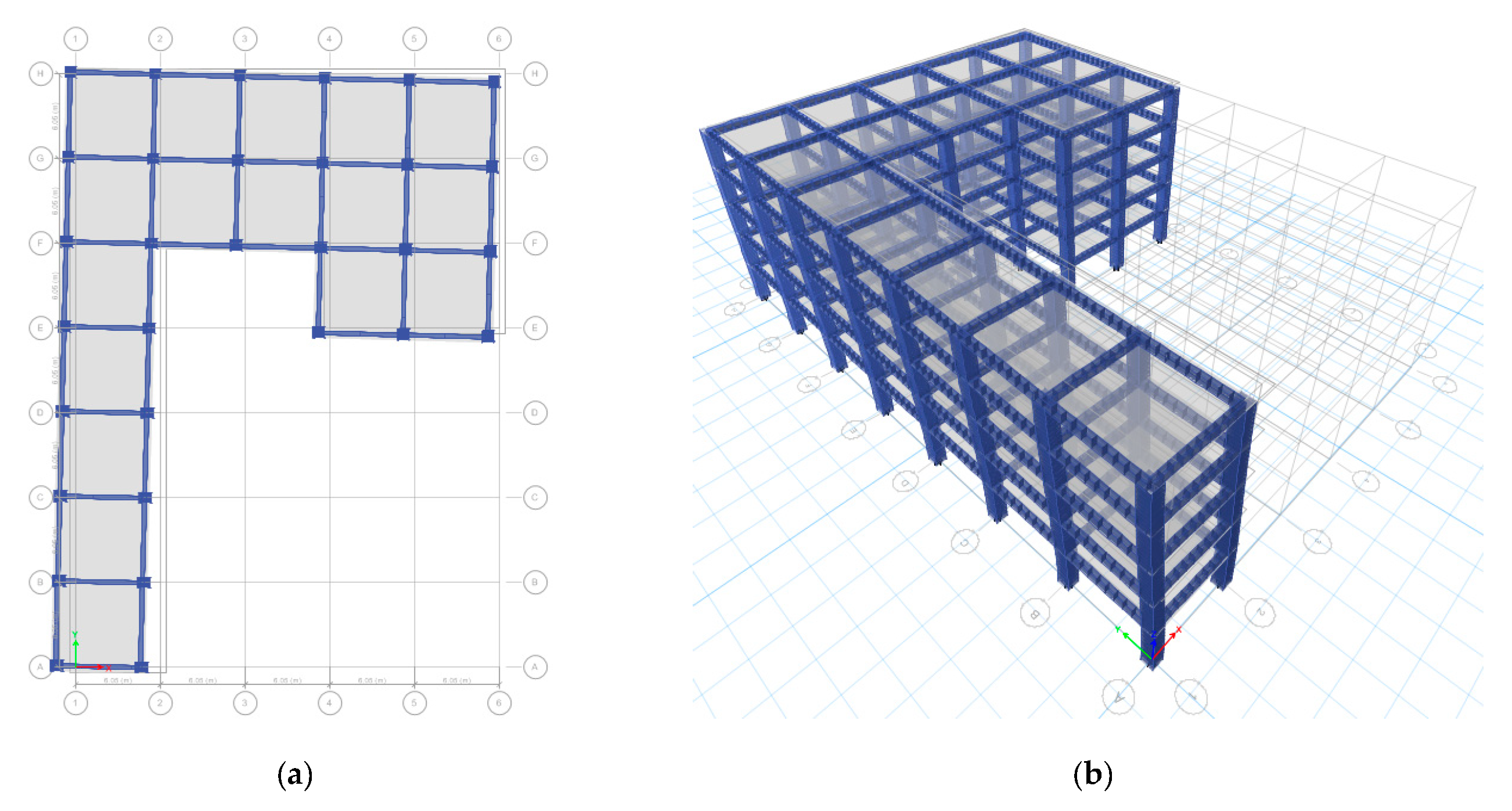
The mode shape 1 for the first civil structure analysed is shown in Figure 5.
In Table 3, the modal participating mass ratios are given for the first three vibration modes.

3.2.2. Case Study 2

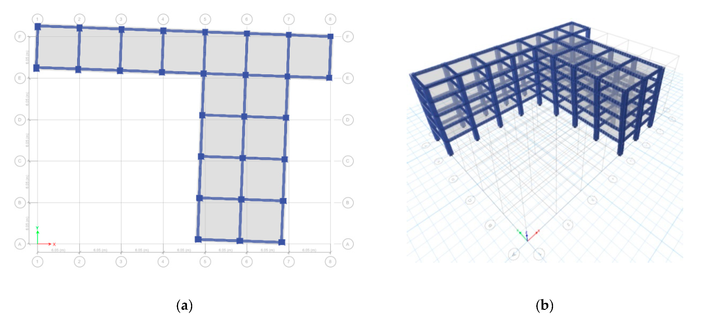
In Table 4, the modal participating mass ratios are given for the first three vibrations modes. The 1st mode shape for the second civil structure analysed is shown in Figure 6.

3.2.3. Case Study 3

In Table 5, the modal participating mass ratios are given for the first three vibrations modes.
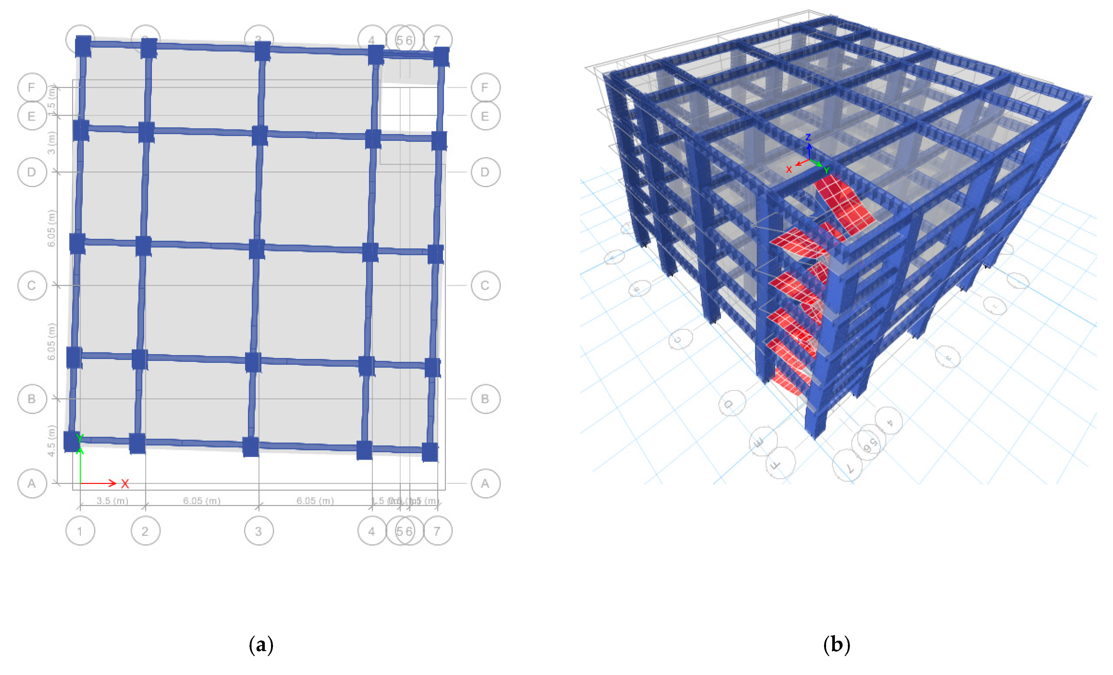
The 1st mode shape for the third civil structure analysed is shown in Figure 7.

3.2.4. Case Study 4

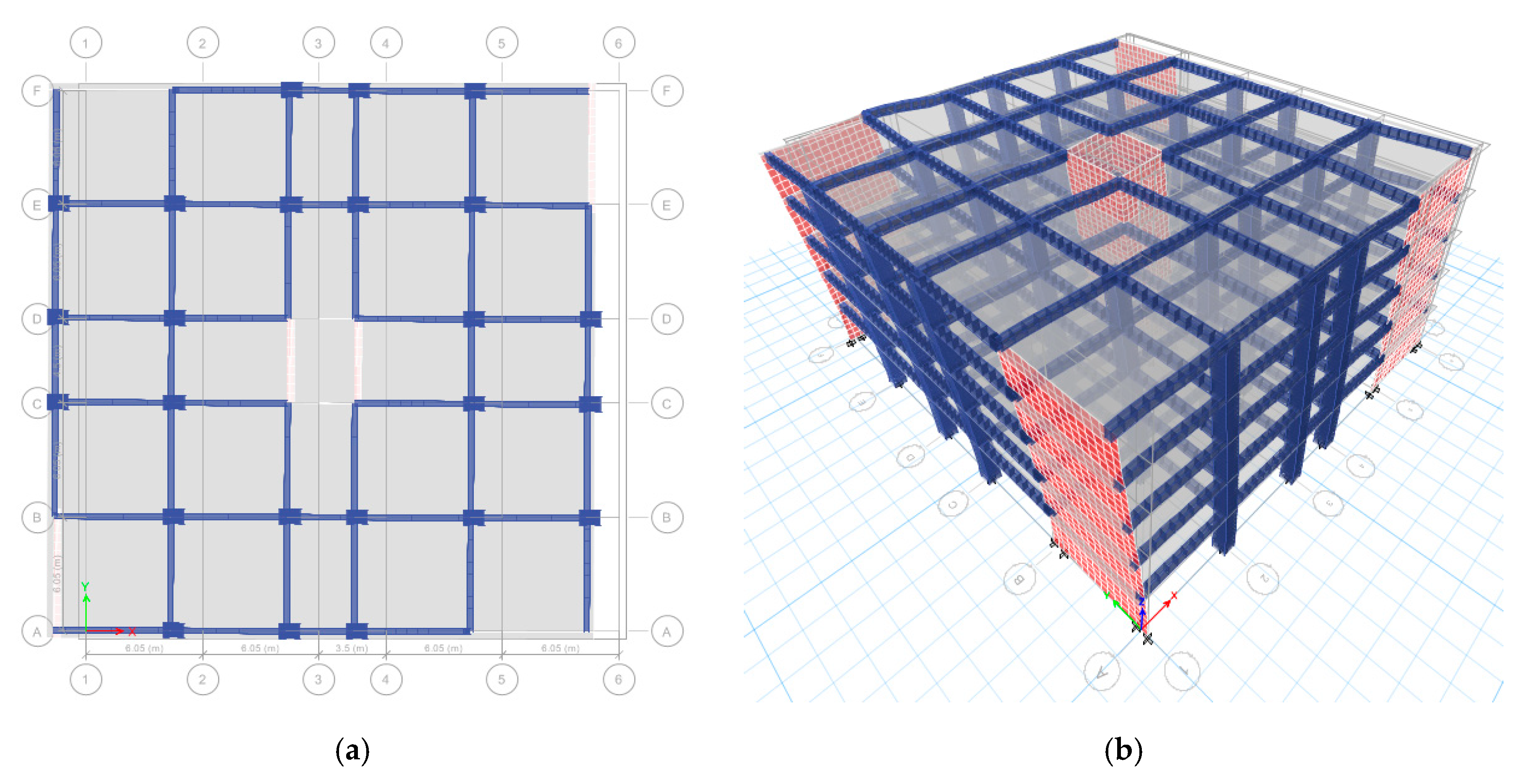
The mode shape 1 for the fourth civil structure analysed is shown in Figure 8. In Table 6, the modal participating mass ratios are given for the first three vibrations modes.

4. Results

4.1. Reduction of Torsion Effect for the Structures

In this section, mathematical and practical solutions to reduce the effect of torsion for the four cases presented in Section 3.2 are shown. For every situation, the optimization process undergoes expressions (27) and (29), and the results of the calculus are presented, for which a modal analysis was performed.
In a general approach, the nonlinear Equation (29) is regulated by a system (43) of inequalities which acts as a restraint for the particular expression of the case, for which two algorithms undergo:
π / 2 α i π / 2 ,     i = 1 ,   6 ¯

4.1.1. Results for Case Study 1

The nonlinear Equations (44) and (45) undergo the optimization process, and the solution is presented by system (46), for which θ 1 = 1.456 · e 7 :
A = 0 + ( 0.161 sin 2 α 1 ) + ( 0.448 sin 2 α 2 ) + ( 0.255 sin 2 α 3 ) + ( 0.161 · sin 2 α 4 ) + ( 0.161 · sin 2 α 5 ) + ( 0.161 · sin 2 α 6 ) ;
B = 0.16560 + ( 0.161 cos 2 α 1 ) + ( 0.448 cos 2 α 2 ) + ( 0.255 cos 2 α 3 ) + ( 0.161 cos 2 α 4 ) + ( 0.161 cos 2 α 5 ) + ( 0.161 cos 2 α 6 ) ;
α 1 = 0.849   rad ;   α 2 = 0.908   rad ;   α 3 = 0.393   rad ; α 4 = 0.314   rad ;   α 5 = 0.785   rad ;   α 6 = 0.785   rad .
The results of the optimization and modal analysis are presented in Table 7 and Figure 9.

4.1.2. Results for Case Study 2

The nonlinear Equations (47) and (48) undergo the optimization process, and the solution is presented by system (49), for which θ 1 = 1.307 e 7 :
A = 0 + ( 0.064 sin 2 α 1 ) + ( 0.123 sin 2 α 2 ) + ( 0.091 sin 2 α 3 ) + ( 0.448 sin 2 α 4 ) + ( 0.161 sin 2 α 5 ) + ( 0.819 sin 2 α 6 ) + ( 0.448 sin 2 α 7 ) + ( 0.312 sin 2 α 8 ) ;
B = 0.50958 + ( 0.064 cos 2 α 1 ) + ( 0.123 cos 2 α 2 ) + ( 0.091 cos 2 α 3 ) + ( 0.448 cos 2 α 4 ) + ( 0.161 cos 2 α 5 ) + ( 0.819 cos 2 α 6 ) + ( 0.448 cos 2 α 7 ) + ( 0.312 cos 2 α 8 ) ;
α 1 = 0.571   rad ;   α 2 = 0.532   rad ;   α 3 = 0.622   rad ;   α 4 = 0.449   rad ; α 5 = 0.349   rad ;   α 6 = 0.349   rad ;   α 7 = 0.524   rad ;   α 8 = 0.449   rad .
The results of the optimization and modal analysis are presented in Table 8 and Figure 10.

4.1.3. Results for Case Study 3

The nonlinear Equations (50) and (51) undergo the optimization process, and the solution is presented by system (52), for which θ 1 = 1.217 e 7 :
A = 0 + ( 0.312 sin 2 α 1 ) + ( 0.024 sin 2 α 2 ) + ( 0.064 sin 2 α 3 ) + ( 0.024 sin 2 α 4 ) + ( 0.161 sin 2 α 5 ) + ( 0.161 sin 2 α 6 ) + ( 0.161 sin 2 α 7 ) + ( 0.064 sin 2 α 8 ) ;
B = 0.14342 + ( 0.312 cos 2 α 1 ) + ( 0.024 cos 2 α 2 ) + ( 0.064 cos 2 α 3 ) + ( 0.024 cos 2 α 4 ) + ( 0.161 cos 2 α 5 ) + ( 0.161 cos 2 α 6 ) + ( 0.161 · cos 2 α 7 ) + ( 0.064 · cos 2 α 8 ) ;
α 1 = 0.654   rad ;   α 2 = 0.628   rad ;   α 3 = 1.047   rad ; α 4 = 0.757   rad ; α 5 = 0.503   rad ;   α 6 = 0.449   rad ;   α 7 = 0.898   rad ;   α 8 = 0.628   rad .
The results of the optimization and modal analysis are presented in Table 9 and Figure 11.

4.1.4. Results for Case Study 4

The nonlinear Equations (53) and (54) undergo the optimization process, and the solution is presented by system (55), for which θ 1 = 1.417 e 7 :
A = 0.02386 + ( 0.312 sin 2 α 1 ) + ( 0.312 sin 2 α 2 ) + ( 0.312 sin 2 α 3 ) + ( 0.312 sin 2 α 4 ) ;
B = 0.61857 + ( 0.312 cos 2 α 1 ) + ( 0.312 cos 2 α 2 ) + ( 0.312 cos 2 α 3 ) + + ( 0.312 cos 2 α 4 ) ;
α 1 = 0.573   rad ;   α 2 = 1.242   rad ;   α 3 = 1.372   rad ;   α 4 = 1.242   rad .
The results of the optimization and modal analysis are presented in Figure 12 and Table 10.

4.2. Special Situations

In this section, three particular situations are analysed: the influence of staircases, structures with torsion sensitivity and structures with geometric irregularity in elevation. Every situation undergoes an optimization process and model analysis was performed before and after optimization.

4.2.1. Influence of Staircases

The results of the modal analysis are presented in Table 11 and Table 12, before and after the reducing of torsion, respectively.
In the same manner, in Figure 13, the initial configuration is shown and the final configuration and behaviour under lateral loads is shown in Figure 14. The optimization in this case consists of modifying the dimensions of some columns located to opposite corners.

4.2.2. Structures with Torsion Sensitivity

The results of the modal analysis are presented in Table 13 and Table 14, before and after the reducing of torsion, respectively.
In the same manner, in Figure 15, the initial configuration is shown and the final configuration and behaviour at lateral loads is shown in Figure 16.
In this case, we use the sensitivity concept from the theoretical part of expressions (40) and (41). This equation was applied on this case and indeed the structure has sensitivity to torsion:
T r o t   T t r = 2 π k m d 2 K φ   · 1 2 π K m i n m = k d 2 K m i n K φ = 1 12 · 1534.58 · 4 215.5 = 1.54 1 ,
where K m i n = 4 ; K φ = 215.5 ; k = 1 / 12 ;   J = k · m d 2 = k · m ( a 2 + b 2 ) ; d 2 = ( a 2 + b 2 ) = 27.7 2 + 27.7 2 = 1534.58 .
To confirm the model analysis, we use the sensitivity concept from the theoretical part at expressions (40) and (41). This equation was applied on this case and indeed the structure has no sensitivity to torsion:
T r o t   T t r = 2 π k m d 2 K φ   · 1 2 π K m i n m = k d 2 K m i n K φ = 1 12 · 1534.58 · 10.2 2617.4 = 0.71 < 1 ,
where K m i n = 10.2 ; K φ = 2617.4 ; k = 1 / 12 ; J = k · m d 2 = k · m ( a 2 + b 2 ) ; d 2 = ( a 2 + b 2 ) = 27.7 2 + 27.7 2 = 1534.58 .

4.2.3. Structures with Vertical Geometric Irregularity or Setback

In this case, the positions of CM and CS are not modified. The concept is similar to case shown in Figure 15 in Section 4.2.2, with the help of modal analysis, and with the results shown in Table 15.
The 1st mode of vibration is shown in Figure 17. In the same manner, the 2nd mode of vibration is shown in Figure 18.
In Figure 19, the spatial behaviour of the structure is presented. One can see that by using the additional elements, torsion can be prevented.

4.3. Discussions on the Results

In order to validate the procedure for the reduction of the overall torsion proposed in this paper, the results obtained by ETABS software and plotted in Table 7, Table 8, Table 9 and Table 10 show that the torsion takes place in the third mode of vibration, after the resizing and changing of the orientation of the columns located at the corners of the multi-storey building. In Figure 9, Figure 10, Figure 11, Figure 12, Figure 13 and Figure 14, it may be observed that the result of the procedure described in this paper consists in the changing of the dimensions and orientations for some perimeter columns.
For the case of the multi-storey building with stairs (Figure 13), the use of the procedure for reducing of the overall torsion leads to the resizing of some columns located to opposite corners, near the stairs (Figure 14). It may be observed again that the torsion is not characteristic for the first mode or for the second mode of vibration after reduction of the overall torsion.
In the case of the multi-storey building with cores (Figure 15) which are torsion sensitive, we may remark that, initially, torsion takes place in the first mode of vibration because the modal participating mass is equal to 0.7815 in rotation with respect to the vertical axis Oz that is parallel to the elevation of the building (Table 13 and Figure 15a). Reduction of the torsion leads to the adding and resizing of the perimeter walls located near the corners of the building. This changing improves the performance of the multi-storey building because the torsion occurs in the third mode of vibration (Table 14 and Figure 16a). It may be observed that after the reducing of the torsion, the modal participating mass is just equal to 0.0008 in rotation with respect to the vertical axis Oz in the first mode of vibration (Table 14).
The results presented in Table 15 and Figure 19 show that the procedure for the reduction of the overall torsion is also validated for the structures with vertical geometric irregularity. The torsion occurs neither in the first mode nor in the second mode of vibration (Table 15).

5. Conclusions

The main purpose of the work was to reduce the distance between CM and CS in the case of multi-storey concrete structures with spatial co-operation through the floors. In this study, multi-storey concrete structures with complex form were analysed in plan, along with the tube effect and the presence of staircases. In the case of civil structures with columns and structural walls, which ensure lateral stiffness of the structure, a heuristic algorithm was used to determine the position of these structural element and to avoid torsion in the first mode of vibration.
From the examples studied in this paper, the following statements may be made:
  • the procedure of optimization can be applied for any kind of geometrical form in plan of the structure to reduce general torsion;
  • the optimized structure way has participating mass in the I and II mode of vibration; in consequence, the response of the structure to seismic loads will be influenced only by the two proper vibration modes mentioned above;
  • due to the fact that in the I and II mode of vibration, the major requirement is bending, it will result in an optimal plastic mechanism, with the capacity of dissipating earthquake-induced energy, due to post-elastic incursions of the structure;
  • the lateral displacements of the optimized structure can be controlled more easily, due to the fact that there are no amplification factors for lateral displacements (drifts), compared to the situation when torsion appears and the storey degradation can be avoided.
In the case of structures with central tubes, the concept of sensitivity to torsion is used, which allows one to determine the position of reinforced concrete walls, to increase K φ , and to avoid torsion.
By using the concept of the sensitivity to torsion, one can compute exactly the length of the perimeter reinforced concrete walls, which are introduced to increase the stiffness of the structure so as the torsion takes place in the 3rd mode of vibration. Elsewhere, the capacity of deformation of the civil structure will decrease and also the capacity of the structure will accumulate deformation energy.
In the last example of the case study, the results obtained in the previous cases of multi-storey reinforced concrete structures with continual structural elements in elevation were extended to structures with withdrawals at the level of particular stories. This example shows that if the line corresponding to CMs and the line corresponding to CSs coincide in a straight line, then the results obtained from multi-storey regulated structures in elevation can be applied to multi-storey irregular structures in elevation.

Author Contributions

Conceptualization, M.F.B.; formal analysis, M.F.B. and C.C.; investigation, M.F.B. and C.C.; methodology, M.F.B.; software, M.F.B.; supervision, M.F.B.; validation, M.F.B. and C.C.; visualization, M.F.B. and C.C.; writing of the original draft, M.F.B. and C.C.; writing—review and editing, C.C. All authors have read and agreed to the published version of the manuscript.

Funding

This research received no external funding.

Acknowledgments

The authors acknowledge the support by Project No. 11002100 between Transilvania University of Brasov and a construction company. The authors also acknowledge the support of Transilvania University of Brasov for providing the software involved and for financial support regarding the publication fees of this article. The authors hereby acknowledge the structural founds project PRO-DD (POS-CCE, O.2.2.1., ID 123, SMIS 2637, ctr. No 11/2009).

Conflicts of Interest

The authors declare no conflict of interest.

References

  1. Alexander, N.A. The role of phase difference components of ground motions in the torsional response of asymmetric buildings. Earthquake Eng. Struct. Dyn. 2007, 36, 1385–1406. [Google Scholar] [CrossRef]
  2. Ministry of Public Works Development and Administration of Romania, M.D.R.A.P. Indicativ P 100-1: 2013. Cod de Proiectare Seismica. PARTEA I — Prevederi de Proiectare Pentru Cladiri. (SEISMIC desIgn code. Part I—Design Provisions for Buildings.); Ministry of Public Works, Development and Administration of Romania: Bucuresti, Romania, 2013.
  3. Naresh Kumar, B.G.; Punith, N.; Bhyrav, R.B.; Arpitha, T.P. Assessment of location of centre of mass and centre of rigidity for different setback buildings. Int. J. Eng. Res. Technol. (IJERT) 2017, 6, 801–804. [Google Scholar] [CrossRef]
  4. Dimova, S.L.; Alashki, I. Seismic design of symmetric structures for accidental torsion. Bull. Earthquake Eng. 2003, 1, 303–320. [Google Scholar] [CrossRef]
  5. Lim, H.K.; Kang, J.W.; Pak, H.; Chi, H.S.; Lee, Y.G.; Kim, J. Seismic response of a three-dimensional asymmetric multi-storey reinforced concrete structure. Appl. Sci. 2018, 8, 479. [Google Scholar] [CrossRef] [Green Version]
  6. Manish, A.K.; Syed, Z.I. Seismic analysis of torsional irregularity in multi-storey symmetric and asymmetric buildings. Eurasian J. Anal. Chem. 2017, 13, 286–292. [Google Scholar]
  7. Zalka, K.A. A simplified method for calculation of the natural frequencies of wall-frame buildings. Eng. Struct. 2001, 23, 1544–1555. [Google Scholar] [CrossRef]
  8. Greco, A.; Fiore, I.; Occhipinti, G.; Caddemi, S.; Spina, D.; Caliò, I. An equivalent non-uniform beam-like model for dynamic analysis of multi-storey irregular buildings. Appl. Sci. 2020, 10, 3212. [Google Scholar] [CrossRef]
  9. Fang, C.; Spencer, B.F.; Xu, J.; Tan, P.; Zhou, F. Optimization of damped outrigger systems subject to stochastic excitation. Eng. Struct. 2019, 191, 280–291. [Google Scholar] [CrossRef]
  10. Xu, J.; Spencer, B.F.; Lu, X.; Chen, X.; Lu, L. Optimization of Structures Subject to Stochastic Dynamic Loading. Comput.-Aided Civ. Infrastruct. Eng. 2017, 32, 657–673. [Google Scholar] [CrossRef]
  11. Xu, J.; Spencer, B.F.; Lu, X. Performance-based optimization of nonlinear structures subject to stochastic dynamic loading. Eng. Struct. 2017, 134, 334–345. [Google Scholar] [CrossRef]
  12. Harbic, C.; Cismas, C.; Dubasaru, V.; Botis, M. Aspects regarding reduction of general torsion in the structures of the braşov campus. Bull. Transil. Univ. Braşov. Ser. I Eng. Sci. 2011, 4, 153–160. [Google Scholar]
  13. Botis, M.F.; Cerbu, C.; Shi, H. Study on the reduction of the general/overall torsion on multi-story, rectangular, reinforced concrete structures. In Proceedings of the 3rd China-Romania Science and Technology Seminar (CRSTS), Transilvania Univ, Brasov, Romania, 24–27 April 2018. [Google Scholar]
  14. Srisangeerthanan, S.; Hashemi, M.J.; Rajeev, P.; Gad, E.; Fernando, S. Numerical study on the effects of diaphragm stiffness and strength on the seismic response of multi-story modular buildings. Eng. Struct. 2018, 163, 25–37. [Google Scholar] [CrossRef]
  15. Ifrim, M. Dinamica Structurilor si Inginerie Seismica (Dynamics of Structures and Earthquake Engineering); Editura didactica si Pedagocica (Didactic and Pedagogical Publishing house): Bucharest, Romania, 1973; pp. 492–514. [Google Scholar]
  16. Doudoumis, I.N.; Doudoumis, N.I. Centres of rigidity in multi-storey asymmetric diaphragm systems for general lateral static loading. Eng. Struct. 2017, 150, 39–51. [Google Scholar] [CrossRef]
  17. Pearl, J. Heuristics: Intelligent Search Strategies for Computer Problem Solving, 1st ed.; Addison-Wesley: Boston, MA, USA, 1984. [Google Scholar]
  18. Nelder–Mead Method. Available online: https://en.wikipedia.org/wiki/Nelder%E2%80%93Mead_method (accessed on 31 May 2020).
  19. Maske, S.G.; Pajgade, P.S. Torsional behaviour of asymmetrical buildings. Int. J. Modern Eng. Res. (IJMER) 2013, 3, 1146–1149. [Google Scholar]
  20. Microsoft. Define and Solve a Problem by Using Solver. Available online: https://support.microsoft.com/en-us/office/define-and-solve-a-problem-by-using-solver-5d1a388f-079d-43ac-a7eb-f63e45925040 (accessed on 10 January 2020).
  21. Pelletier, K.; Leger, P. Nonlinear seismic modeling of reinforced concrete cores including torsion. Eng. Struct. 2017, 136, 380–392. [Google Scholar] [CrossRef] [Green Version]
  22. MathWorks Inc. MATLAB. Math. Graphics. Programming. Available online: https://www.mathworks.com/products/matlab.html (accessed on 10 January 2020).
  23. Computers and Structures Inc. ETABS—Integrated Analysis, Design and Drafting of Building Systems. Available online: https://www.csiamerica.com/products/etabs (accessed on 10 January 2020).
Figure 1. The rigidity factor corresponding to a unitary displacement applied on: (a) x axis, and (b) y axis.
Applsci 10 05555 g001
Figure 2. Representation of the physical signification of the stiffness factors.
Applsci 10 05555 g002
Figure 3. Flow chart of program (by using Matlab software) for calculus in order to minimize the distance between centre of mass (CM) and centre of stiffness (CS) and to cancel the angle θ (orientation of the principal rigidity axes).
Applsci 10 05555 g003
Figure 4. Prescribed diaphragm classification.
Applsci 10 05555 g004
Figure 5. The 1st mode shape for T1 = 0.471 s: (a) plane view and (b) 3D view.
Applsci 10 05555 g005
Figure 6. The 1st mode shape for T1 = 0.482 s: (a) plane view, and (b) 3D view.
Applsci 10 05555 g006
Figure 7. The 1st mode shape for T1 = 0.480 s: (a) plane view, and (b) 3D view.
Applsci 10 05555 g007
Figure 8. The 1st mode shape for T1 = 0.481 s: (a) plane view, and (b) 3D view.
Applsci 10 05555 g008
Figure 9. The 1st mode shape for T1 = 0.433 s: (a) plane view, and (b) 3D view.
Applsci 10 05555 g009
Figure 10. The 1st mode shape for T1 = 0.414 s: (a) plane view, and (b) 3D view.
Applsci 10 05555 g010
Figure 11. The 1st mode shape for T1 = 0.449 s: (a) plane view, and (b) 3D view.
Applsci 10 05555 g011
Figure 12. The 1st mode shape for T1 = 0.451 s: (a) plane view, and (b) 3D view.
Applsci 10 05555 g012
Figure 13. The 1st mode shape for T1 = 0.385 s: (a) plane view, and (b) 3D view.
Applsci 10 05555 g013
Figure 14. The 1st mode shape for T2 = 0.376 s: (a) plane view, and (b) 3D view.
Applsci 10 05555 g014
Figure 15. The 1st mode shape for T1 = 0.389 s before the reducing of the torsion: (a) plane view, and (b) 3D view.
Applsci 10 05555 g015
Figure 16. The 1st mode shape for T1 = 0.239 s after the reducing of the torsion: (a) plane view and (b) 3D view.
Applsci 10 05555 g016
Figure 17. The 1st mode shape for T1 = 0.519 s: (a) plane view of the 1st floor, and (b) plane view of the 10th floor.
Applsci 10 05555 g017
Figure 18. The 2nd mode shape for T2 = 0.512 s: (a) plane view of the 1st floor, and (b) plane view of the 10th floor.
Applsci 10 05555 g018
Figure 19. First two modes: (a) the 1st mode, and (b) the 2nd mode.
Applsci 10 05555 g019
Table 1. Input data corresponding to the structure.
Number of Stories5
Ground storey height3.50 (m)
Intermediate storey height3.00 (m)
Slab thickness15 (cm)
Beam sizeB1 = 30 × 55 (cm2)
Column sizeC1 = 80 × 80 (cm2)
Grade of concreteC 20/25
Grade of steelBST 500S
Density of concrete25 (kN/m3)
Super dead load1.3 (kN/m2)
Live load3 (kN/m2)
Roof load2 (kN/m2)
Table 2. Earthquake data computed according to [2].
Location, CountryVrancea Area, Romania
ag (m/s2)3.924
TC (s)1.0
TB (s)0.20
TD (s)3.00
Importance factor1.00
Framing typeD.C.H.
Behaviour factor6.75
Base shear coefficient, c0.10
ν0.45
Damping (%)5
Table 3. Modal participating mass ratios before the reducing of the torsion.
ModePeriodUXUYRZSum UXSum UYSum RZ
(s)
10.4710.55970.22120.02310.55970.22120.0231
20.470.23260.57120.00110.79220.79240.0242
30.4410.01270.01260.77930.80490.8050.8035
Table 4. Ratios of the modal participating mass before the reducing of the torsion.
ModePeriodUXUYRZSum UXSum UYSum RZ
(s)
10.4820.60370.03240.15970.60370.03240.1597
20.4650.16160.40610.2390.76530.43860.3987
30.4470.03670.36810.40190.8020.80670.8005
Table 5. Ratios of the modal participating mass before the reducing of the torsion.
ModePeriodUXUYRZSum UXSum UYSum RZ
(s)
10.480.12930.40040.26610.12930.40040.2661
20.4680.3090.36890.12640.43830.76920.3925
30.4460.36710.03290.40540.80540.80220.7978
Table 6. Ratios of the modal participating mass before the reducing of the torsion.
ModePeriodUXUYRZSum UXSum UYSum RZ
(s)
10.4810.40790.38980.0080.40790.38980.008
20.4630.40030.40290.00630.80820.79270.0143
30.3030.000040.0140.83070.80830.80670.8451
Table 7. Ratios of the modal participating mass after the reducing of the torsion.
ModePeriodUXUYRZSum UXSum UYSum RZ
(s)
10.4330.00020.7750.00010.00020.7750.0001
20.4160.76890.00020.00020.76910.77530.0003
30.2490.00020.00010.83070.76930.77530.831
Table 8. Ratios of the modal participating mass after the reducing of the torsion.
ModePeriodUXUYRZSum UXSum UYSum RZ
(s)
10.4140.01040.73840.02660.01040.73840.0266
20.3970.74430.01240.00150.75470.75080.0282
30.30.00330.0210.77990.75810.77180.8081
Table 9. Ratios of the modal participating mass after the reducing of the torsion.
ModePeriodUXUYRZSum UXSum UYSum RZ
(s)
10.4490.00430.77580.00170.00430.77580.0017
20.4370.77140.00490.00910.77570.78070.0107
30.3040.0080.00130.79770.78370.7820.8084
Table 10. Ratios of the modal participating mass after the reducing of the torsion.
ModePeriodUXUYRZSum UXSum UYSum RZ
(s)
10.4510.76810.01970.00010.76810.01970.0001
20.4060.0210.74730.00190.78910.7670.002
30.2710.000020.00310.79650.78910.77010.7985
Table 11. Ratios of the modal participating mass before the reducing of the torsion.
ModePeriodUXUYRZSum UXSum UYSum RZ
(s)
10.3850.00280.79250.01660.00280.79250.0166
20.3650.78270.00570.02590.78550.79820.0426
30.330.02850.01360.77090.8140.81180.8135
Table 12. Ratios of the modal participating mass ratios after the reducing of the torsion.
ModePeriodUXUYRZSum UXSum UYSum RZ
(s)
10.3760.00010.80540.000040.00010.80540.00004
20.3560.80780.00010.00080.8080.80550.0008
30.320.00050.00020.80410.80850.80570.8049
Table 13. Ratios of the modal participating mass before the reducing of the torsion.
ModePeriodUXUYRZSum UXSum UYSum RZ
(s)
10.3890.03500.78150.03500.7815
20.3410.747800.03620.782800.8177
30.31400.765600.78280.76560.8177
Table 14. Ratios of the modal participating mass after the reducing of the torsion.
ModePeriodUXUYRZSum UXSum UYSum RZ
(s)
10.2390.757100.00080.757100.0008
20.22900.75130.00080.75710.75130.0008
30.1850.00080.000000.75310.75790.75130.7531
Table 15. Ratios of the modal participating mass.
ModePeriodUXUYRZSum UXSum UYSum RZ
(s)
10.5190.617600.000040.617600.00004
20.51200.615400.61760.61540.00004
30.3560.000100.53160.61760.61540.5317