Article

Feasibility Study and Prospects of Rock Fragmentation Using Ultrasonic Vibration Excitation

1
Jiangsu Engineering Laboratory of Mine Earthquake Monitoring and Prevention, China University of Mining & Technology, Xuzhou 221116, China
2
School of Mines, China University of Mining and Technology, Xuzhou 221116, China
3
Chongqing Energy Investment Group Science & Technology Co., LTD, Chongqing 400061, China
*
Author to whom correspondence should be addressed.
Appl. Sci. 2020, 10(17), 5868; https://doi.org/10.3390/app10175868
Submission received: 14 July 2020 / Revised: 20 August 2020 / Accepted: 21 August 2020 / Published: 25 August 2020
(This article belongs to the Section Applied Industrial Technologies)

Abstract

:
This paper systematically examines the feasibility of using ultrasonic vibration excitation for rock breakage and fragmentation; it focuses on the failure mechanisms of rock mass under the impact of ultrasonic waves, and the development of ultrasonic technology. Laboratory testing using a self-designed system was conducted in this paper to further validate the efficiency and reliability of rock breakage using ultrasonics. The results show that: (i) under the effects of both the high speed impact of ultrasonic vibration excitation and induced rock vibration excitation, a fracture is initiated and propagates rapidly within and outside of the rock. Under ultrasonic vibration excitation for 140 s, the compressive strength decreased by 45.6%; (ii) under the excitation of ultrasonics, the rock specimens failed completely in a short time from inside to outside, and there are distinct fissures in the internal nucleation of the rock. It is suggested that ultrasonic excitation provides a novel and promising option for rock fragmentation and breakage, which optimises the efficiency of underground hard rock engineering.

1. Introduction

Rock breakage and fragmentation have played an increasing role in civil and mineral sectors, and one of the challenges is to improve the efficiency of rock fragmentation by reducing the material consumption [1]. There are a number of literatures available on the study of the optimised methodology used for rock breakage and fragmentation, based on various rock fragmentation mechanisms [2,3]. The existing methods mainly include drilling and blasting, hydraulic fracturing, and thermal fracturing. However, these methods normally have the disadvantages of the serious wear of drill pipes, slow borehole drilling speed, large loss of machine tools and energy consumption, high costs, and unsatisfactory working efficiency in field application, especially when they are adapted to optimise hard rock breakage and fragmentation.
Ultrasound has been successfully utilised in many different areas, such as medicine [4,5] and petroleum engineering [6]. With regards to rock breakage and fragmentation, many scholars have carried out studies on ultrasonic drilling machines and lapping machines and achieved a series of results. Li et al. [7] and Sun et al. [8] studied the influence of the vibration frequency of acoustic drilling machines on rock breakage by theoretical calculation and field monitoring, and found that the drilling speed of acoustic drilling machines is 5 times that of ordinary drilling machines. This provides a theoretical basis for improving the rock-crushing performance of acoustic drilling machines. Yin et al. [9] tested the compressive strength of rock samples at different static load levels by changing the size of the upper static load when ultrasonic excitation was applied to coal samples and studied the dynamic process of fracture development of rock samples with the application of CT scanning. It was concluded that the strength of rock samples decreases with the increase of the static load applied to the upper part of the samples. Neeson, E. and Lucas, M. [10] performed laboratory experiments to analyze the fracture development characteristics of saturated porous rocks under ultrasonic excitation. The results revealed that ultrasonic excitation can effectively increase the porosity of samples and reduce rock strength, which proves the feasibility of the ultrasonic vibration excitation method in rock engineering. Fheed et al. [11,12] and Węglarz et al. [13] used nuclear magnetic resonance (NMR) and computed microtomography to study the three-dimensional morphology of fractures in fractured rock masses. This research method has important reference value for the study of the fracture morphology of rock samples after ultrasonic vibration. Tang et al. [14] carried out experimental studies on ultrasonic cracking to increase the permeability of coal seams. They used ultrasonic waves to conduct vibration excitation on coal samples, combined with NMR observation technology and electron microscope scanning technology to understand the variation of pore sizes of coal samples against excitation time, and disclosed that ultrasonic high-frequency vibration can increase the porosity of coal samples.
In this paper, the fracture development and fracture evolution characteristics of red sandstone, granite, marble and limestone specimens under ultrasonic vibration excitation are studied. It is proved that ultrasonic vibration excitation can effectively break these four kinds of hard rocks. It is found through statistical analysis of the compressive strength of the rocks that ultrasonic vibration excitation can effectively reduce the compressive strength of rock samples.

2. Overview of Rock Breakage Methods

Rock breakage methods generally include mechanical rock breakage and thermal rock breakage based on different mechanisms. The current rock breakage methods and their characteristics are summarised as shown in Table 1. Overall, the more commonly used rock breakage method is mechanical rock breaking, which is, however, limited by the equipment and working environment. The methods such as thermal rock breakage have not yet been applied on a large scale.

3. The Theoretical Feasibility of Ultrasonic Rock Breakage

The natural frequency of rock is above 7–20 kHz, and similarly the ultrasonic frequency is above 20 kHz. Therefore, the ultrasonic technology is introduced into the hard rock fragmentation. By adjusting the ultrasonic frequency to approximate the natural frequency of the rock, the method can cause the rock to vibrate, and stimulate the fracture imitation and propagation so as to improve the rock breakage efficiency.
The use ultrasonic technology in rock breakage has been examined in the 1950s, by the former Soviet Union Binke Kerr. They focused on the ultrasonic mechanical effects, cavitation, and the mixture of these two aspects. The technical requirements for rock breakage by ultrasonic waves were advanced theoretically. Of note is that due to the limitations on the research conditions at that time, there was no huge progress in that research. With the improved understanding of the role of ultrasound and the continuous development of large-scale ultrasonic generator manufacturing technology in recent decades, the mechanism of using ultrasonic waves on rock mechanics is becoming clearer, and using ultrasonic waves for rock breakage is becoming a promising option.

3.1. Mechanisms of Ultrasonic Action on Rock Mass

Ultrasound is a sound wave with frequency higher than 20 kHz, and is in the form of mechanical vibration and energy transfer. When ultrasonic waves propagate in rock mass, physical and chemical changes of the rock occur due to the interaction of the ultrasonic waves with the two-phase or multi-phase media, resulting in a series of mechanical, thermal, electromagnetic, and chemical ultrasound effects. It is believed that the mechanisms of ultrasonic action include four important elements, being mechanical action, cavitation effect, thermal effect, and chemical action. This section will mainly focus on the mechanical and cavitation effects on the rock mass.
(1) Mechanical effects
During the process of ultrasonic wave propagation, the compression and expansion of the medium particles will lead to a change of pressure between the mediums. This pressure change will cause a mechanical effect between the mediums, which is mainly reflected by the change of the origin displacement, vibration velocity, acceleration, and sound pressure parameters [16]. Due to the short wavelength and the high frequency, the particle vibration caused by ultrasonic waves is minimal, but the mass acceleration, proportional to the square of the ultrasonic frequency, is significantly large—up to 3000 times that of the acceleration of gravity. Therefore, a small static stress can cause a huge impact load, and the effect stress will far exceed the strength of the rock, resulting in the formation of fine cracks at the rock surface, then followed by fracture propagation [17]. Based on this mechanism, ultrasound has been well used in the processing of stiff and brittle material.
(2) Cavitation
Cavitation is a unique form of ultrasonic action that can be categorised into steady-state cavitation and transient cavitation [18]. When the ultrasonics works on liquid, the resulting local high negative pressure can initiate a large number of voids or bubbles. As the energy of the ultrasonic wave increases, the liquid will undergo significant tensile stress. When the ultrasonic energy reaches a certain threshold, the bubbles will rapidly expand; then they suddenly break and cleave into more small bubbles and they generate a shock wave. The interaction between steady-state cavitation and transient cavitation contributes to the reactions including oscillation, growth, contraction, and other processes [19]. Currently, in the cutting and drilling using water jets, the introduction of ultrasonic cavitation can further improve work efficiency [20].

3.2. Ultrasonic Vibration Excitation Mechanisms for Rock Breakage

(1) Ultrasonic mechanical rock breakage
When the ultrasonic impact load reaches the fatigue failure threshold of the rock under static stress, each impact will further reduce its strength. Due to the high frequency of the ultrasonic wave, the fatigue failure threshold of the rock decreases rapidly in a short period of time, thereby optimising the rock fragmentation.
In the process of ultrasonic excitation of rock, the P wave is in the same direction of micro particle vibration; therefore, the particles are under compressive stress and tensile stress that alternately change at a high frequency, accordingly leading to tension and compression deformation. The propagation of the S wave induces shear stress on the rock micro particles, and therefore accounts for the shear deformation. The adjacent rock micro-particles are continually subjected to tensile stress, compressive stress, and shearing stress, and the contacts between particles are constantly under the effects of friction, deformation, and damage, leading to the initiation of microcracks. Under the continuous excitation of the ultrasonic wave, the microcracks continue to propagate, expand, and pierce the rock to form large cracks. With the increase of ultrasonic excitation time, the large cracks inside the rock mass continue to develop, penetrate, and form the fracture network for the rock breakage.
The effective ultrasonic sound pressure is described in Equation (1) [21]:
p e = 2 U I ω A S ,
where U is the working voltage of the ultrasonic generator, I is the working current of the ultrasonic generator, ω is the ultrasonic vibration frequency, A is the vibration amplitude, and S is the area of the ultrasonic contact action.
Considering the rock strength σ0, when peσ0, the micro-cracks in the rock mass initiate, propagate, and penetrate, leading to the rock damage, that is as described in Equation (2):
2 U I ω A S σ 0 .
The equation above can be used to derive the ultrasonic frequency range for the formation of microcracks as in Equation (3):
ω 2 U I σ 0 A S .
Outside this frequency range, the ultrasonic excitation will not cause damage to the rock and does not contribute to the crack propagation inside the rock. All the ultrasonic energy is dissipated in the form of elastic waves and the rock is hardly damaged by fatigue loading. Within this frequency range, part of the ultrasonic energy is dissipated in the form of elastic waves, and the remainder is used for the propagation of cracks and formation of the new surface area. Each action of ultrasonic excitation can cause cracks within the rock mass. Under these conditions, cyclic loading with constant amplitude can lead to the accumulation of rock damage until reaching fatigue failure [9]. Within the effective ultrasonic frequency range, the higher the frequency of ultrasonic excitation is, the faster the fatigue damage occurs to the rock; and the longer the ultrasonic excitation time is, the higher the damage degree of the rock.
Therefore, from the perspective of rock breakage using impact loading, the ultrasonic method is applicable, and its high frequency makes the method very competitive.
(2) Ultrasonic resonance
When the impact frequency generated by ultrasonic excitation reaches the natural frequency of the rock, the rock will resonate. When the single impact load is the same under the resonance effect, the effective energy of the impact load acting on the rock will be greater per unit time, which contributes to the rapid development of fracture propagation within the rock mass.
The competent rock normally has a natural frequency from 15 kHz to 40 kHz, while the ultrasonic frequency is above 20 kHz; therefore, the ultrasonic frequency can reach most of the natural frequencies of the rock, making the rock resonate, to promote crack propagation within the rock and to improve the rock crushing efficiency. This is an important feature of ultrasonic rock breakage, compared to the general rock breakage methods that use high frequency vibration excitation.

4. Engineering Application and Progress of Ultrasonic Excitation of Coal and Rock Mass

4.1. Application of Power Ultrasound in Underground Mining Engineering

At present, ultrasonic power has been successfully used in underground mines, especially in the field of outburst forecasting, coal and rock mass flaw detection, and supplementary rock breaking. The associated research outcomes mainly include the following three aspects:
(1) Detection of damage characteristics of coal and rock mass (specimen) given its penetration and attenuation characteristics in the solid. For example, Hauwaert et al. [22] and Xie et al. [23] used an ultrasonic testing system to test the crack propagation in steel fiber reinforced concrete beams, and the surrounding rock stability, fracture development within the coal mass in roadways, respectively. The results show that ultrasonic technology has advantages in rock flaw detection, which is characterized by a strong penetrating power of the ultrasonic wave and a large detectable depth; easy identification of damage flaw positions; high sensitivity and small detectable fracture scale; and fast reaction time and results visualization.
(2) Enhance the crack propagation of coal and rock mass by ultrasonic vibration excitation. Based on theoretical analysis, Xiao et al. [21] studied the influence of power ultrasound on the development of fractures and the mechanical properties of coal and rock samples (see Figure 1) using CT microscopy. The work provides evidence of using power ultrasound to prompt the fracture development in the coal and rock mass, therefore changing their mechanical properties.
(3) The use of ultrasonic vibration excitation (cavitation) and mechanical impact to optimise rock breakage. Based on the physical characteristics of ultrasonic energy coupling, Yang [24] studied the sampling of extraterrestrial space ultrasonic impact drilling and preliminary design of the drilling prototype (see Figure 2). The preliminary test results are promising.

4.2. High-Power Ultrasound Equipment

Ultrasonic mechanical effects and cavitation effects are closely related to the ultrasonic power. As the core of ultrasonic devices, the development of the ultrasonic generator determines the application of ultrasonic technology.
Currently the ultrasonic generator has a frequency of tens to thousands of kilohertz, and is powered from tens of watts to hundreds of kilowatts. The matching ultrasonic transducers have a frequency of 10 to 500 kHz, and the output power reaches more than ten kilowatts. Harbin Institute of Technology has developed an ultrasonic power source with a maximum power of 160 kW [25] and a 10 kW ultrasonic transducer [26] (see Figure 3).
At the same time, the successful development of high-power ultrasound equipment further expands the scope of application of ultrasound technology. Pu et al. [27] used self-developed ultra-high-power ultrasonic equipment to increase the permeability of the rock mass in the wells in petroleum engineering. It helps to further expand and connect oil channels, and at the same time, cemented asphaltene molecular bonds break to reduce the viscosity of crude oil and increase the fluidity of crude oil. After the ultrasonic treatment, the daily output of experimental wells can be increased by 100% or more.

4.3. Rock Breakage Test Using Ultrasonic Excitation

The effect of ultrasonic excitation on rock damage was experimentally studied. Excitation and crushing tests were carried out on rock specimens of different sizes using a custom-made ultrasonic excitation rock test device which was developed by us (see Figure 4). The rock specimens were collected from red sandstone, granite, marble, and limestone. Each specimen had dimensions of 50 mm (in diameter) × 100 mm (in height). A compressive loading of 20 N was applied to the top of the specimen. The fracture length and the failure time of the specimen during ultrasonic excitation were observed and recorded. The ultrasonic power was 2.6 kW, with a frequency of 20 kHz. The physical experiment schemes are shown in Table 2.
The authors conducted preliminary tests using ultrasonic excitation for rock breakage. Take the specimen with a size of Φ 50 × 100 mm, and carry out the ultrasonic excitation experiment under the additional static pressure of 20 N. Observe the expansion and the development of longitudinal and transverse cracks of the specimen every 10 s, including the number of cracks, the crack expansion speed, types of cracks, etc. The ultrasonic power is 2.6 kW, with a frequency of 20 kHz. The physical experiment schemes are shown in Table 2.
The test process is shown in Figure 5.
During the test, a certain loading was applied to the rock specimen. Under the ultrasonic excitation, the rock produced a large amount of dust within 1 min. After 3 min, the section contacted by the rock specimen and the tool head was obviously fractured. Localised fracturing into powder occurred at the upper half of the specimen. After 5 min, when the test was finished, the majority of the specimens had completely failed.
The experimental results are listed in Table 3.
The representative limestone specimen that shows obvious fracture development in Section 4.1 is selected as an example. In order to study the fracture development characteristics of the specimen, high resolution 3D-X ray microimaging system (3D-XRM) scanning was performed; the specimen was loaded by a compressive loading of 20 N with an excitation time of 50 s. The specimen in the scanning experiment has dimensions of 50 mm (in diameter) × 100 mm (in height). Since the maximum scanning height in each 3D-XRM scanning process is 50 mm, the height of the final scanning image if also 50 mm. The scanning results are provided in Figure 6.
It can be seen from Figure 6 that with the increase of excitation time, the internal fractures of limestone specimens are continuously expanding and developing, the number of fractures is continuously increasing, and the internal longitudinal expansion depth is continuously increasing. This is mainly due to the fact that the ultrasonic wave can be divided into a shear wave and a longitudinal wave, in the process of internal propagation in limestone. The shear wave will make the rock micro particles subject to the shear stress perpendicular to the direction of ultrasonic propagation and then subject to shear deformation. The longitudinal wave will make the rock micro particles subject to the high-frequency alternating pressure and tensile stress and then subject to tension and compression deformation.

4.4. Evolution Characteristics of Microcracks in Specimens under Ultrasonic Excitation

The representative red sandstone specimen is selected as an example to investigate the evolution characteristics of microcracks in a specimen under ultrasonic excitation. The SEM scanning results of the red sandstone specimen before and after ultrasonic excitation are given in Figure 7.
The crystal nucleus of the red sandstone is tightly wrapped by mortar before ultrasonic excitation. The surface is flat and intact (i.e., no obvious microcracks). When a static loading of 20 N and ultrasonic excitation are applied, due to the existence of the original defects (e.g., microcracks, pores and crystal nucleus boundaries), the alternating stress induced by ultrasonic excitation promotes the generation and accumulation of damage at the defects. Microcrack networks between the crystals are formed, and then the microcracks further propagate. With the increase of excitation time, the temperature of the crystal nucleus continuously increases due to vibration and friction and its volume expands, which leads to further propagation of the microcracks between the crystals. However, the propagation speed of the microcracks declines. The crystal nucleus fractures once the temperature reaches a certain degree, and microcracks between crystals are generated. These microcracks propagate and penetrate the whole crystal nucleus and finally cut the crystal nucleus into small pieces, which results in the fracture of the crystal nucleus.

4.5. Strength Characteristics of Specimen after Ultrasonic Vibration Excitation

With the development of ultrasonic excitation, the edge of the specimen first produces radial cracks which gradually extend to the radial centre of the specimen with the extension of the excitation time. After 50 s of excitation, the radial cracks basically run through the whole diameter surface of the specimen, and then with the extension of the excitation time, new cracks are generated on the upper surface of the specimen; these cracks continue to expand and connect, and they distribute in a divergent manner around the excitation contact surface.
As the selected material is hard and dense red sandstone, the specimens have high compressive strength (shown in Table 4), with a compressive strength value of 53.6 MPa. After 140 s of ultrasonic excitation at a frequency of 20 kHz, the compressive strength value is reduced from 53.6 MPa to 36.8 MPa, as shown in Figure 8, and the compressive strength is reduced by 45.6%. The compressive strength of the specimen decreases linearly with an increase of time, and the fitting curve formula is y = −0.0971x + 50.343. An obvious breaking of the rock can be seen as the effect of the ultrasonic vibration excitation.

5. Future Development and Prospects

In summary, researchers over the world have a certain level of understanding of the mechanisms of using ultrasonic excitation for rock breakage and fragmentation. Laboratory tests were conducted using high power ultrasonic waves to reveal the specific characteristics and microscopic performance of the ultrasonic excitation rock damage. It is foreseeable that in the future using ultrasonic excitation for rock breakage will be one of the important aspects in rock engineering, significant to rapid construction in underground engineering, such as tunneling in hard rock.
However, the current researches mainly focus on the small scale, low power, and light weight crushing and processing of small size materials. The understanding of the rock breaking mechanism under the action of ultrasonic excitation and the associated rock resonance and mechanical impact still needs to be improved. The feasibility of using the technique for in-situ rock breaking at large geological bodies in underground engineering needs to be further explored. Under the in-situ condition, the coupled response of “ultrasonic wave-rock mass-fracture flow” needs to be further improved. The structural parameters of ultrasonic rock breaking equipment and their impact on the overall rock breaking effect still need to be improved.
In the present study, 3D-XRM scanning and SEM scanning are applied to study the microcracking process and failure characteristics of rock specimens. In a future study, NMR will be adopted to investigate the distributions of pore structures of rock specimens after ultrasonic excitation; such investigation will further optimise the 3D presentation of the fracture morphology.
With the continuous increase of coal mining depth and the continuous improvement of technical requirements for underground engineering, a single rock breaking method cannot fully meet the requirements of high efficiency, energy conservation, and maintenance of environmentally friendly conditions in mines. Ultrasonic technology has significant advantages in improving the current rock breakage methods for rapid and efficient underground structure development.

6. Conclusions

A series of laboratory experiments were performed to study the fracture evolution in rock specimens before and after ultrasonic excitation, microcracking in the specimens, and the influence of ultrasonic excitation on the compressive strength of the rock specimens. The following conclusions are made based on the experimental results.
  • Ultrasonic excitation experiments were designed and performed on different rock types. Microcracks generate and cause the failure of the specimen in relatively short experimental time and under a relatively low axial stress, due to ultrasonic excitation. The fracture length and the fracture propagation speed under ultrasonic excitation are rock-type dependent. The granite specimen and the limestone specimen have the minimum “average maximum fracture length” and the maximum “average maximum fracture length”, respectively. The granite specimen has the shortest failure duration. All four rock types show the characteristics of “no macroscopic fracture-fracture generation-steady fracture propagation”.
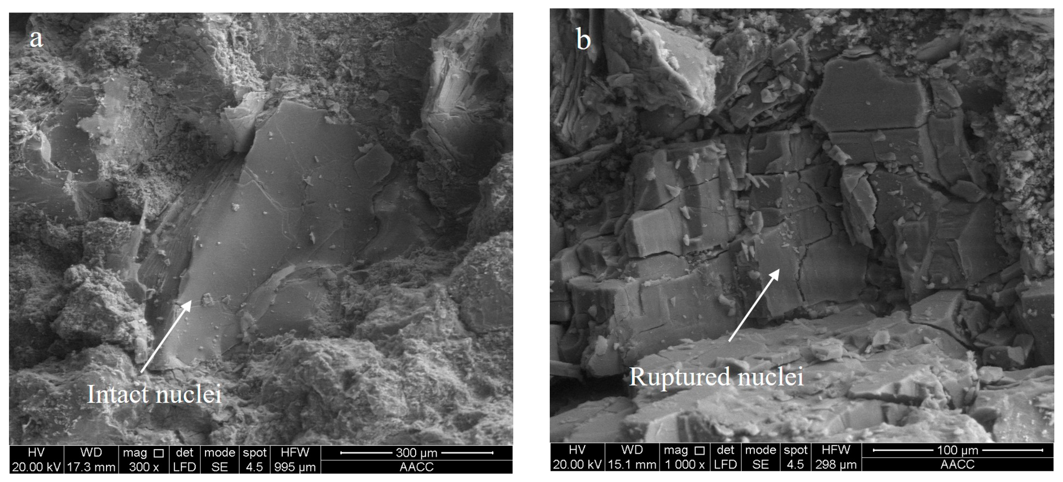
  • Energy continuously accumulates in the rock specimen as the time of ultrasonic excitation increases. This phenomenon not only leads to the generation of macroscopic fractures, but also causes the formation of microcracks that propagate along crystal boundaries and penetrate crystals. The development of these microcracks notably decreases the compressive strength of the rock specimens. The experimental results show that the compressive strength of red sandstone specimens decreases by 45.6 % after 140 s of ultrasonic excitation.
  • Traditional rock breakage technology has the disadvantages of high energy consumption, high costs, and low efficiency. Ultrasonic excitation will become one of the important approaches to the effective breakage of hard rocks. It is highly significant to further investigate the mechanism of ultrasonic excitation and to develop relevant equipment in order to apply the mechanism to high-speed construction involving hard rock breakage.

Author Contributions

Data curation, X.W. (Xufeng Wang); formal analysis, X.W. (Xuanlin Wang) and J.W.; methodology, X.W. (Xufeng Wang); writing—original draft, J.W.; Writing—review and editing, Z.T. All authors have read and agreed to the published version of the manuscript.

Funding

This research was supported by the National Natural Science Foundation of China (No.51874282), and the Six Talent Peaks Project in Jiangsu Province (No.GDZB-052). The authors are grateful for these supports.

Conflicts of Interest

The authors declare no conflict of interest.

Data Availability

The data used to support the findings of this study are available from the corresponding author upon request.

References

  1. He, Q.; Li, Y.; Xu, J.; Zhang, C. Prediction of Mechanical Properties of Igneous Rocks under Combined Compression and Shear Loading through Statistical Analysis. Rock Mech. Rock Eng. 2019, 53, 841–859. [Google Scholar] [CrossRef]
  2. Liu, J.; Jiang, Y.; Zhao, Y.; Zhu, J. Uniaxial compression CT and acoustic emission test on the coal crack propagation destruction process. J. Coal Sci. Eng. (China) 2013, 19, 69–74. [Google Scholar] [CrossRef]
  3. Patadiya, D.M.; Jaisankar, S.; Sheshadri, T.S. Detonation initiated disintegration of coal particle due to the maximum strain energy theory. J. Coal Sci. Eng. (China) 2013, 19, 435–440. [Google Scholar] [CrossRef]
  4. Critello, C.D.; Fiorillo, A.S.; Matula, T.J. Size of Sclerosing Foams Prepared by Ultrasound, Mechanical Agitation, and the Handmade Tessari Method for Treatment of Varicose Veins. J. Ultrasound Med. 2017, 36, 649–658. [Google Scholar] [CrossRef] [PubMed] [Green Version]
  5. Critello, D.C.; Pullano, S.A.; Gallo, G.; Matula, T.J.; Fiorillo, A.S. Low frequency ultrasound as a potentially viable foaming option for pathological veins. Colloids Surfaces A Physicochem. Eng. Asp. 2020, 599, 124919. [Google Scholar] [CrossRef]
  6. Taheri-Shakib, J.; Shekarifard, A.; Naderi, H. The experimental investigation of effect of microwave and ultrasonic waves on the key characteristics of heavy crude oil. J. Anal. Appl. Pyrolysis 2017, 128, 92–101. [Google Scholar] [CrossRef]
  7. Li, X.; Harkness, P.; Worrall, K.; Timoney, R.; Lucas, M. A Parametric Study for the Design of an Optimized Ultrasonic Percussive Planetary Drill Tool. IEEE Trans. Ultrason. Ferroelectr. Freq. Control. 2017, 64, 577–589. [Google Scholar] [CrossRef]
  8. Sun, L.; Bu, C.; Hu, P.; Xia, B. The transient impact of the resonant flexible drill string of a sonic drill on rock. Int. J. Mech. Sci. 2017, 122, 29–36. [Google Scholar] [CrossRef]
  9. Yin, S.; Zhao, D.; Zhai, G. Investigation into the characteristics of rock damage caused by ultrasonic vibration. Int. J. Rock Mech. Min. Sci. 2016, 84, 159–164. [Google Scholar] [CrossRef]
  10. Neeson, E.; Lucas, M. The effects of ultrasonics in fragmentation of saturated porous rock samples. Ultrasonics Symp. 2012, 1982–1985. [Google Scholar] [CrossRef]
  11. Fheed, A.; Kłodowski, K.; Krzyżak, A. Fracture orientation and fluid flow direction recognition in carbonates using diffusion-weighted nuclear magnetic resonance imaging: An example from Permian. J. Appl. Geophys. 2020, 174, 103964. [Google Scholar] [CrossRef]
  12. Fheed, A.; Krzyżak, A.; Świerczewska, A. Exploring a carbonate reef reservoir—Nuclear magnetic resonance and computed microtomography confronted with narrow channel and fracture porosity. J. Appl. Geophys. 2018, 151, 343–358. [Google Scholar] [CrossRef]
  13. Weglarz, W.P.; Krzyzak, A.; Machowski, G.; Stefaniuk, M. ZTE MRI in high magnetic field as a time effective 3D imaging technique for monitoring water ingress in porous rocks at sub-millimetre resolution. Magn. Reson. Imaging 2018, 47, 54–59. [Google Scholar] [CrossRef] [PubMed]
  14. Tang, Z.; Zhai, C.; Zou, Q.; Qin, L. Changes to coal pores and fracture development by ultrasonic wave excitation using nuclear magnetic resonance. Fuel 2016, 186, 571–578. [Google Scholar] [CrossRef]
  15. Thirumalai, K. Rock Mechanics and Development of Advanced Hard Rock Breaking Methods. Appl. Rock Mech. 1975, 1975, 449–467. [Google Scholar]
  16. Tong, J.L.; Yan, Y.Y.; Zhao, B. Ultrasonic-Vibration Hard Cutting Force Analysis with the Finite Element Method. Key Eng. Mater. 2010, 455, 360–364. [Google Scholar] [CrossRef]
  17. Sajjady, S.A.; Nouri Hossein Abadi, H.; Amini, S.; Nosouhi, R. Analytical and experimental study of topography of surface texture in ultrasonic vibration assisted turning. Mater. Des. 2016, 93, 311–323. [Google Scholar] [CrossRef]
  18. Harichandran, R.; Selvakumar, N. Effect of nano/micro B4C particles on the mechanical properties of aluminium metal matrix composites fabricated by ultrasonic cavitation-assisted solidification process. Arch. Civ. Mech. Eng. 2016, 16, 147–158. [Google Scholar] [CrossRef]
  19. Prikhod’ko, V.M.; Aleksandrov, V.A.; Fatyukhin, D.S.; Petrova, L.G. Effect of Ultrasonic Cavitation on Nitrided Steel Surface Layer Condition. Met. Sci. Heat Treat. 2015, 57, 300–303. [Google Scholar] [CrossRef]
  20. Aoyagi, R.; Fujiwara, R.; Niita, T. Possibility of Metal Processing Using Ultrasonic Cavitation Jet. Jpn. J. Appl. Phys. 2001, 40, 3784–3786. [Google Scholar] [CrossRef]
  21. Xiao, X.; Pan, Y.; Lu, X.; Yang, X. Mechanism of methane permeability enhance through ultrasonic irradiating on low permeable coal seam. Chin. J. Geophys. 2013, 56, 1726–1733. [Google Scholar]
  22. Hauwaert, A.V.; Thimus, J.F.; Delannay, F. Use of ultrasonics to follow crack growth. Ultrasonics 1998, 36, 209–217. [Google Scholar] [CrossRef]
  23. Xie, F.; Ji, B.; Yuan, Z.; Fu, Z.; Ge, H. Ultrasonic Detecting Method and Repair Technology Based on Fatigue Crack Features in Steel Box Girder. J. Perform. Constr. Facil. 2016, 30, 04015006. [Google Scholar] [CrossRef]
  24. Yang, K. Research on Drilling Corer Based on Ultrasonic/Acoustic Energy Coupling Mechanism. Master’s Thesis, Nanjing University of Aeronautics and Astronautics, Nanjing, China, 2012. [Google Scholar]
  25. Yang, G. 160kW Ultrasonic Power Source. China Patent CN102882360A, 1 January 2013. [Google Scholar]
  26. Zhang, Y. The Optimization of Structural Parameters of the Oil Production Increasing Ultrasonic Transducer Based on Electromechanical Coupling. Master’s Thesis, Harbin Institute of Technology, Harbin, China, 2014. [Google Scholar]
  27. Pu, C.; Shi, D.; Zhao, S.; Xu, H.; Shen, H. Technology of removing near wellbore inorganic scale damage by high power ultrasonic treatment. Pet. Explor. Dev. 2011, 38, 243–248. [Google Scholar] [CrossRef]
Figure 1. Fracture development under ultrasonic vibration excitation.
Applsci 10 05868 g001
Figure 2. The drilling prototype.
Applsci 10 05868 g002
Figure 3. High-power ultrasonic equipment: (a) a 160 kW ultrasonic generator structure diagram; and (b) a 10 kW ultrasonic transducer.
Applsci 10 05868 g003
Figure 4. Test setup for ultrasonic excitation loading test.
Applsci 10 05868 g004
Figure 5. The test process of ultrasonic vibration excitation: (a) at the start; (b) during the test; and (c) after finished.
Applsci 10 05868 g005
Figure 6. Fracture development characteristics of rocks.
Applsci 10 05868 g006
Figure 7. Mineral grain nucleus within the rock using SEM: (a) prior to ultrasonic vibration excitation; and (b) after ultrasonic vibration excitation.
Applsci 10 05868 g007
Figure 8. Excitation time versus compression strength curve.
Applsci 10 05868 g008
Table 1. Summary of rock breakage methods [15].
Category MethodsMechanismCharacteristic
Mechanical energy rock breakageBlasting The borehole is filled with explosives and the rock is broken by the energy generated by explosivesLarge disturbance, inconsistency in rock fragmentation, relies on drilling, difficult to automate
Mechanical breakageUse the energy generated from the mechanical cutting rig Low efficiency, rigs are prone to wear out easily
Water jet methodUse of a high-pressure water jet to increase the rock’s free surface and increase cutting depthAffected by the pressure factors of a high-pressure water pump (domestic pumps generally do not exceed 35 MPa), difficult to carry out for large scale hard rock crushing
Projectile impactGas is fired at the bottom of the shallow borehole, resulting in pulse pressure and the formation of tensile stress Low material consumption, the broken rock section is easy to control
Thermal
rock breakage
Plasma methodUnder the high-temperature and high-speed plasma arc, the thermal stress generated exceeds the strength limit of the rock, thereby crushing the rockSuitable for hard rock breakage, but prone to deflection
Laser methodUse of laser heat to crush the rockLow cost; easier to be affected by the development of laser technology, rock types and road sections
Microwave methodThe rock mass is heated by microwaves to change its petrophysical propertiesLow level of vibration, flying rock ejection and noise; microwave equipment and the life of the oscillator are difficult to determine
Table 2. Physical experiment schemes.
LithologySize/mmStatic Pressure/NTime/sGroup Count
SandstoneΦ50 × 10020604
GraniteΦ50 × 10020604
MarbleΦ50 × 10020604
LimestoneΦ50 × 10020604
Table 3. Failure of different rock types under ultrasonic excitation.
Rock TypeBefore Ultrasonic ExcitationAfter Ultrasonic ExcitationMaximum Fracture Length (mm)Average Failure Time(s)
Red sandstone Applsci 10 05868 i001 Applsci 10 05868 i00230.1663
Granite Applsci 10 05868 i003 Applsci 10 05868 i00428.3294.6
Marble Applsci 10 05868 i005 Applsci 10 05868 i00636.1510.5
Limestone Applsci 10 05868 i007 Applsci 10 05868 i00847.3343.2
Table 4. Physical and mechanical parameters of the specimens.
E/GPaμR/MPaRm/MPaθC/MPa
700.2553.66.0142.3818.15

