Article

A Quality Study of a Self-Piercing Riveted Joint between Vibration-Damping Aluminum Alloy and Dissimilar Materials

1
Advanced Welding & Joining R&BD Group, Korea Institute of Industrial Technology, 156 Gaetbeol-ro, Incheon 21999, Korea
2
Department of Mechanical and Systems Design Engineering, Hongik University, 94 Wausan-ro, Mapo-gu, Seoul 04066, Korea
*
Authors to whom correspondence should be addressed.
Appl. Sci. 2020, 10(17), 5947; https://doi.org/10.3390/app10175947
Submission received: 5 August 2020 / Revised: 15 August 2020 / Accepted: 26 August 2020 / Published: 27 August 2020
(This article belongs to the Section Mechanical Engineering)

Abstract

:

Featured Application

This work has application in the manufacturing of electric vehicles and other environmentally friendly means of transportation where use of novel multi-materials is required.

Abstract

This study investigates the quality of self-piercing riveted joints between vibration-damping aluminum (Al) and other dissimilar materials, namely aluminum alloy (AL5052-H32), steel alloy (GA590DP), and carbon-reinforced plastic (CFRP). The effects of die types (flat, cone, and nipple) on the geometrical characteristics and mechanical performance of the joints are studied using a cross-section examination and tensile shear load testing. The failure modes of each joint are also presented, showing the nature of the forces leading to the joint failures. The results indicate that, for all configurations, adequate joining between vibration-damping Al with AL5052-H32 is expected with a maximum shear load up to 3.28 kN. A shear load up to 3.6 kN was measured for the joints with GA590DP panels with acceptable top and bottom seal characteristics. A vibration-damping Al panel can only be positioned at the bottom when riveting with CFRP due to the brittle nature of CFRP. A tensile shear load up to 2.26 kN was found, which is the lowest amongst the materials tested in this study.

1. Introduction

Self-piercing riveting (SPR) is a method used for mechanically attaching similar or dissimilar materials [1]. The process works by creating an interlock between the top and the bottom sheets or panels using a rivet that fully penetrates the top but not the bottom panel. SPR has several advantages: (1) a simple process with no requirement of predrilled holes [2], (2) easy automation and a short cycle time with excellent reproducibility [3], (3) no dust, chips, and heat fumes as associated with a welding process [4], (4) eco-friendly and sustainable, since no waste material is produced [5], and (5) very little or no damage to pre-coated materials [3]. The process is especially useful in joining dissimilar materials such as carbon fiber reinforced plastic (CFRP) [6,7,8], copper [9], titanium [9], aluminum alloys [10,11], and steel [11,12], in which the use of conventional joining methods is challenging.
In the modern auto-industry, the use of functional and lightweight materials such as aluminum alloy, high-strength steel, and carbon composites is increasing [13,14]. Vibration-damping aluminum (Al) panels are now being widely used to form cowl and dash panels for increased passenger comfort and overall weight reduction of the vehicles. The use of such dissimilar materials requires efficient means of joining, since the conventional fusion joining methods are not applicable. Up to now, despite their drawbacks, non-fusion methods, including chemical bonders and conventional mechanical fasteners, have been used. The toxic chemicals comprising the bonders pose severe health and environmental risks, while the conventional mechanical joining methods require manual alignment of panels that is difficult to automate [15]. Therefore, the industry is shifting to fasteners that need no prefabricated holes, such as SPR [16,17], clinching [18,19], and flow drill screw (FDS) [20]. Nevertheless, limited studies are available, in the open academic literature, discussing novel methods for joining dissimilar materials [21].
The effects of the rivet and die types on SPR of aluminum alloy (AA6061) and mild steel (CR4) were investigated by Ma et al. [22] under various processing configurations. An experimental and numerical investigation of the self-piercing rivet joint between aluminum alloy (A5052-H34) and mild steel (SPCC) was done by Abe et al. [23]. The mechanical characteristics of self-piercing riveted joints in multiple layers composed of aluminum (AA6111 and NG5754) and steel alloys (HSLA350) were studied by Han et al. [24]. The performance of various self-piercing riveted joints (tension, shear, and peel joint) using aluminum sheets (A5754) was investigated by Wood et al. at standard car crash test speeds [25]. The joint quality of self-piercing riveted CFRP/aluminum, steel/aluminum, and CFRP/steel/aluminum with three layers was investigated by our group [7,8,9]. The bonding quality of self-piercing riveted joints of vibration-damping steel and aluminum alloy was also recently studied by our group [26]. Nevertheless, to the best of the authors’ knowledge, no comprehensive study has been performed for SPR between novel materials used in the automotive industry such as vibration-damping aluminum (Al), aluminum alloy, steel alloy, and carbon-reinforced plastic (CFRP).
Here, we investigate the geometrical characteristics and mechanical performance of the SPR of vibration-damping Al with aluminum alloy (AL5052-H32), steel alloy (GA590DP), and thermoset CFRP. The differences are studied of the geometrical and mechanical characteristics of the joints according to the specimen configuration and die type. Three types of dies are used to form the rivet joints, and the cross-section is examined to investigate the joint quality of different panel configurations. The joint qualities (or joining strengths) were determined using a series of tensile shear load tests, and the failure modes were examined to shed light on the critical forces acting on the joints that eventually lead to their failures.

2. Materials and Methods
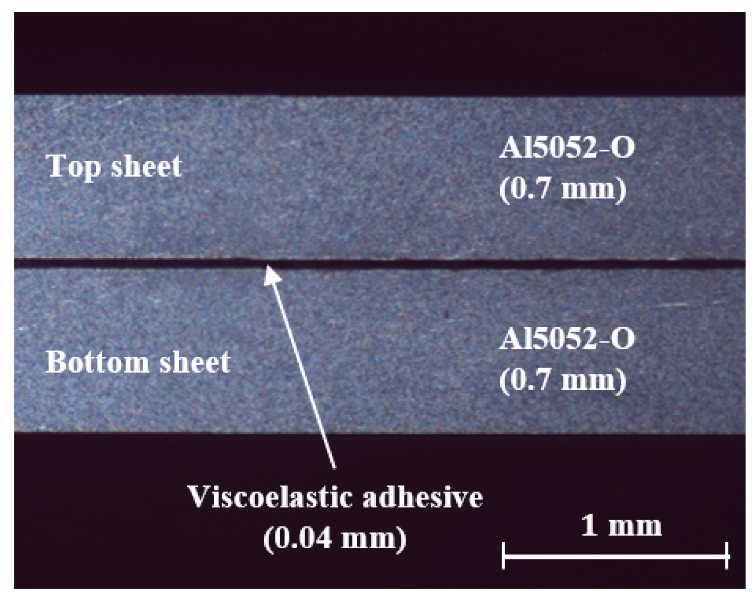
2.1. Materials

The materials used here were vibration-damping Al, aluminum alloy (Al5052-H32), steel alloy (GA590DP), and a thermoset CFRP 7 cross-ply (at 0° and 90° angles) laminated structure in an epoxy matrix. As shown in Figure 1, the vibration-damping Al panel consists of two Al5052-O sheets (with a thickness of 0.7 mm) bound by a 0.04 mm thick viscoelastic adhesive polymer layer. The strengths and the thicknesses of the materials used are listed in Table 1, evaluated using ASTM E8M specified samples.

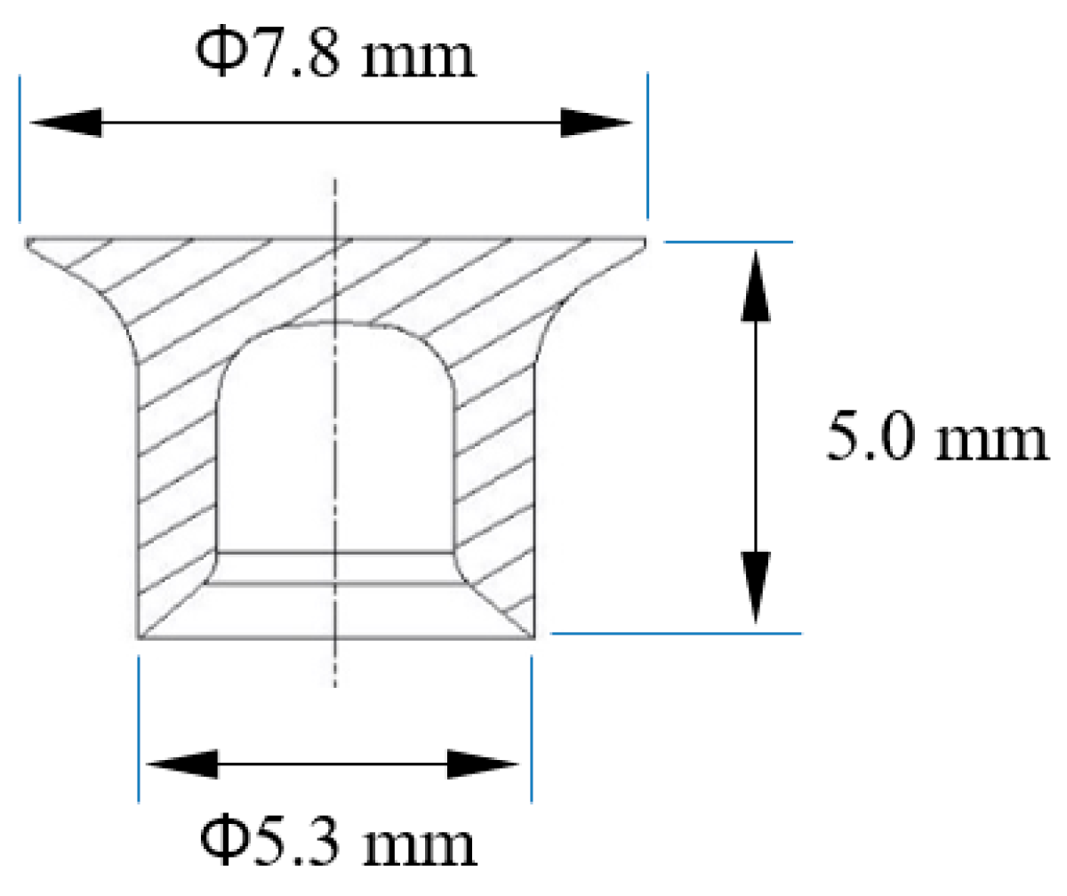
2.2. Rivet Fabrication and Die Types

Self-piercing riveted joints were formed by Rivset Gen2 (manufacturer: BÖLLHOFF, Bielefeld, Germany) a hydraulic riveting machine. A rivet made out of boron steel with an Almac® coating (a combination of Zn, Sn, and Al) was used that has a hardness of 480 ± 30 HV. The shank diameter and the length of the rivet were 5.3 mm and 5.0 mm, respectively, as shown in the dimensional specifications of the rivet in Figure 2. Three die shapes (manufactured by BÖLLHOFF) were tested and detailed descriptions of the dies are presented in Figure 3. Die type A (diameter: 8.8 mm; depth: 1.8 mm) is the benchmark die with a flat bottom profile. Die type B (diameter: 9.0 mm; depth: 1.8 mm) and type C (diameter: 9.0 mm; depth: 2.0 mm) both have bulging profiles with different shapes (cone and nipple) at the center of the die cavity. A die-to-rivet volume ratio, R, of approximately 1.2 was chosen to remove any experimental bias due to the volume ratio.

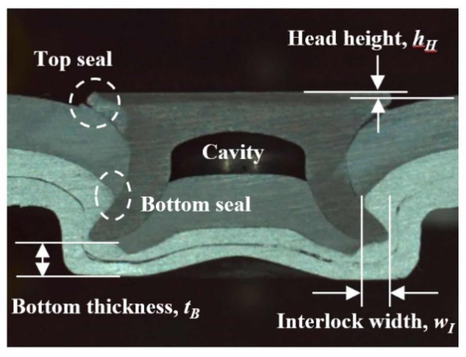
2.3. Cross-Section Analysis of Self-Piercing Riveted Joints

The geometrical characteristics of the joints were studied using the cross-sections shown in Figure 4, prepared by cutting the joints using a band saw and then polishing. Three geometrical indexes were measured: (1) head height, hH (the distance between the rivet head and the top panel), (2) interlock width, wI (the distance from the tip of the deformed rivet shank to the pierced point of the bottom panel), and (3) bottom thickness, tB (the remaining thickness of the bottom panel after the riveting process was complete). Before the main SPR experiments, the setting forces (or the riveting load) of the riveting machine were carefully predetermined and set between approximately 28 and 43 kN, so that all of the joints had a head height, hH, of 0 ± 0.05 mm. The head heights of the joints were measured using a dial gauge, and the interlock widths and the bottom thicknesses were measured by an optical microscope system equipped with image analysis software. The top seal was the intersection between the rivet head and the top panel, and the bottom seal was the intersection between the rivet leg and the bottom panel, as shown in the figure.

2.4. Joint Strength Test Apparatus

The strength of the joint was examined by a tensile shear test (Universal Testing Machine, AG-300KNX (manufacturer: Shimadzu, Kyoto, Japan) with a maximum load capacity of 30 tons). The test procedure conformed to KS B ISO 14273 standards, and the specimen is shown in Figure 5. The tensile shear tests were carried out at a crosshead speed of 5 mm/min.

3. Results and Discussion

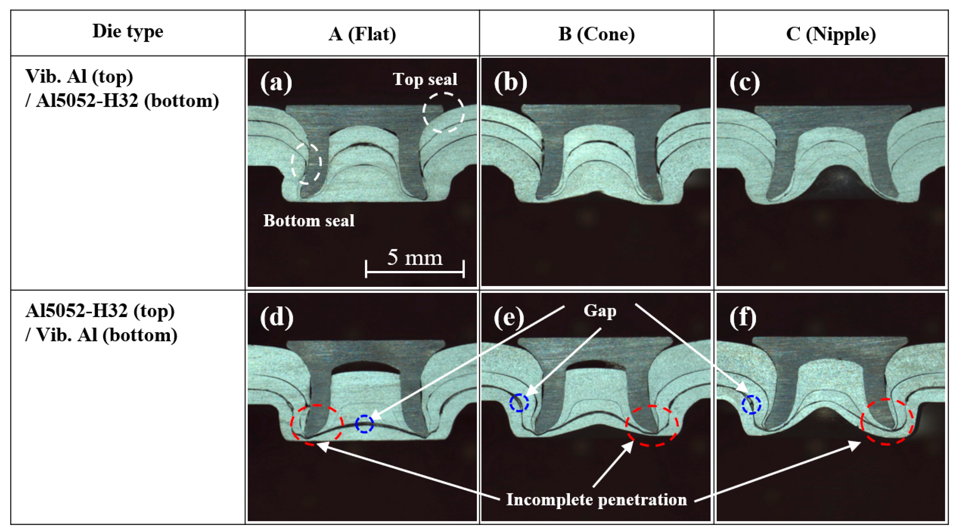
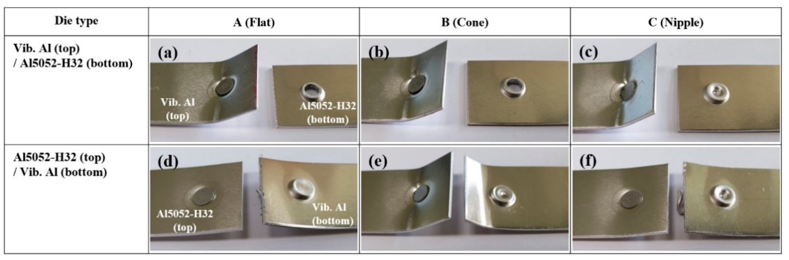
3.1. Self-Piercing Riveted Joint of Vibration-Damping Aluminum and Al5052-H32

In this section, the quality of the self-piercing riveted joint formed between vibration-damping Al and Al5052-H32 is investigated. The cross-sectional views of the joints are shown in Figure 6. Three different die type profiles (A, B, and C), as shown in Figure 3, and two different configurations of panels (the vibration-damping Al panel on top and the AL5052-H32 panel on the bottom, and vice versa) were used to form the joints. The top images show that when the vibration-damping Al panel is on top, good top sheet penetration of the rivet is observed with minimal gaps between the two sheets comprising the vibration-damping Al. The figure shows that die type C produces the maximum seal qualities for the joint while die type B causes gaps within the top and bottom seals. The joint formed using die type A shows that the rivet tip is surrounded by the debris from the vibration-damping Al, but complete penetration of the top panel is evident, so that an interlock has been formed between the two panels. When the vibration-damping Al panel is on the bottom, as shown in the bottom images, the rivet does not completely penetrate the top panel, so that the interlock width is not clearly defined. In addition, local gaps between the two aluminum sheets are evident, although there is no complete separation between the two sheets due to the adhesive. Nevertheless, all joints show successful joining between the top and the bottom panels with marginal defects.
The geometrical indexes, namely, interlock width, wI, and bottom thickness, tB, were measured along with the tensile shear loads, and the results are shown in Figure 7. The results in Figure 7a show that the geometrical indexes do not show significant differences between the die types, within the margin of error, when the vibration-damping Al panel is on top. The value for the configuration when the vibration-damping panel is on the bottom could not be measured since the rivet tip did not completely penetrate the bottom panel. The tensile shear test results, shown in Figure 7b, indicate that for the configuration where the vibration-damping Al panel is on top, the maximum tensile shear load of 3.28 kN results for the joint formed using die type C, consistent with the highest seal quality found in Figure 6. Tensile shear loads of 2.79 KN and 2.54 kN were measured for the joints formed using die type A and die type B, respectively. Although there were defects present for the configuration when the vibration-damping Al panel was positioned on the bottom, the panels remained joined; therefore, tensile shear tests were carried out. The results show that a maximum tensile shear load of 2.8 kN results for the joint formed using die type B but is significantly lower compared with that of the joint with the highest cross-sectional quality (the joint formed using die type C under vibration-damping Al in the top configuration).
The failure modes of the joints after the tensile shear tests were examined, and the results are shown in Figure 8. The figure shows that for the configuration where the vibration-damping panel was on top, no failure of the vibration-damping Al panel was observed for all of the joints. The joint failure eventually occurred by “rivet pull-out” failure accompanied by “bottom sheet crack” for (a) and (b), while only by “rivet pull-out” failure for (c). The bottom sheet cracks were formed due to the relatively small tB resulting from the riveting process, which was 0.11 mm for the joint formed using die type A and 0.12 mm for the joint formed using die type B. The joint formed using die type C resulted in a relatively high tB of 0.15 mm and thus did not form any cracks. The absence of a bottom sheet crack could be the reason behind the maximum tensile shear load results shown in Figure 7. In the configurations where the vibration-damping panel was on the bottom, the joint failure occurred only by “rivet pull-out” accompanied by the bottom sheet tearing from the vibration-damping Al panel. This can be seen in Figure 8d–f.

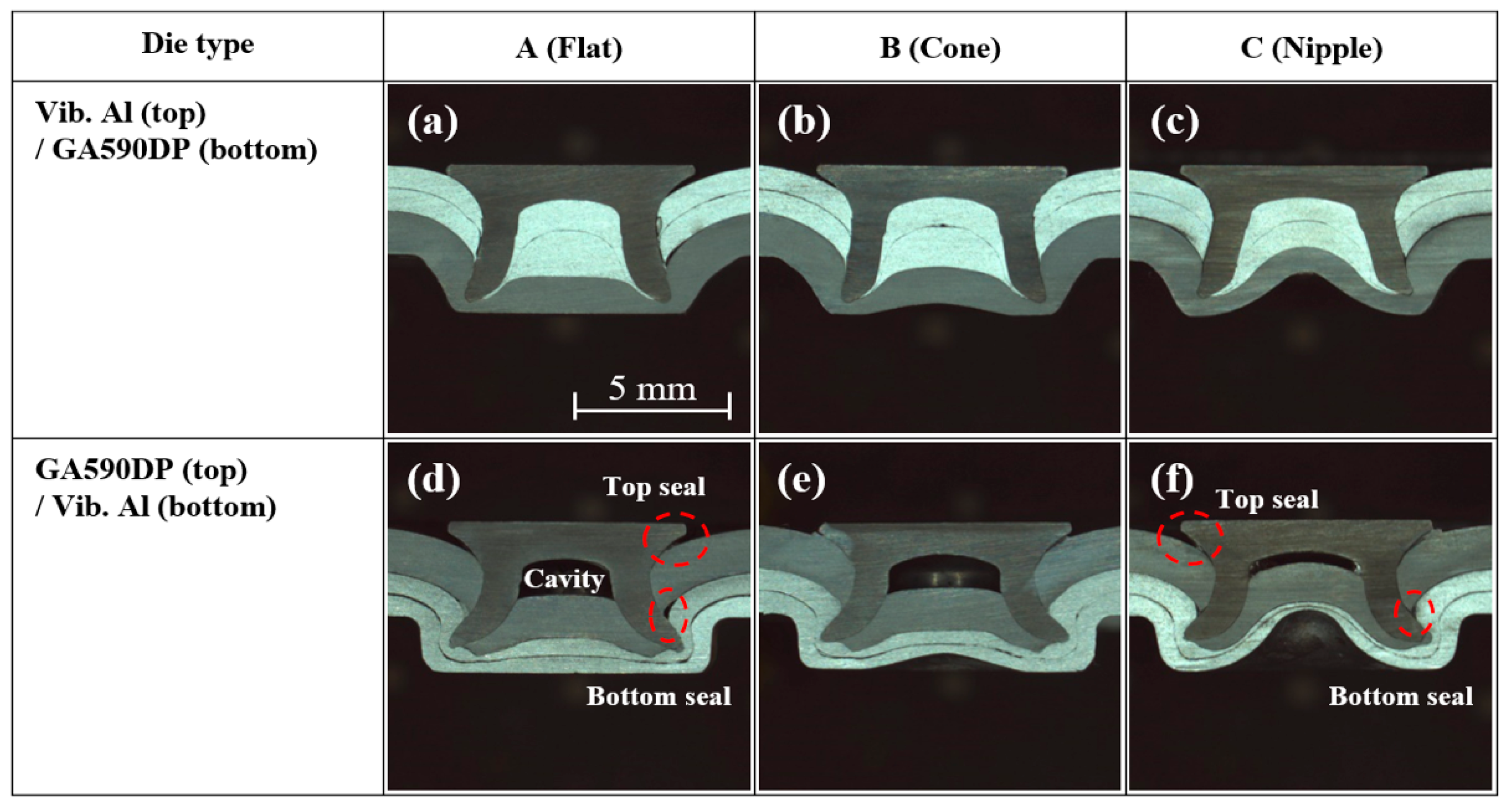
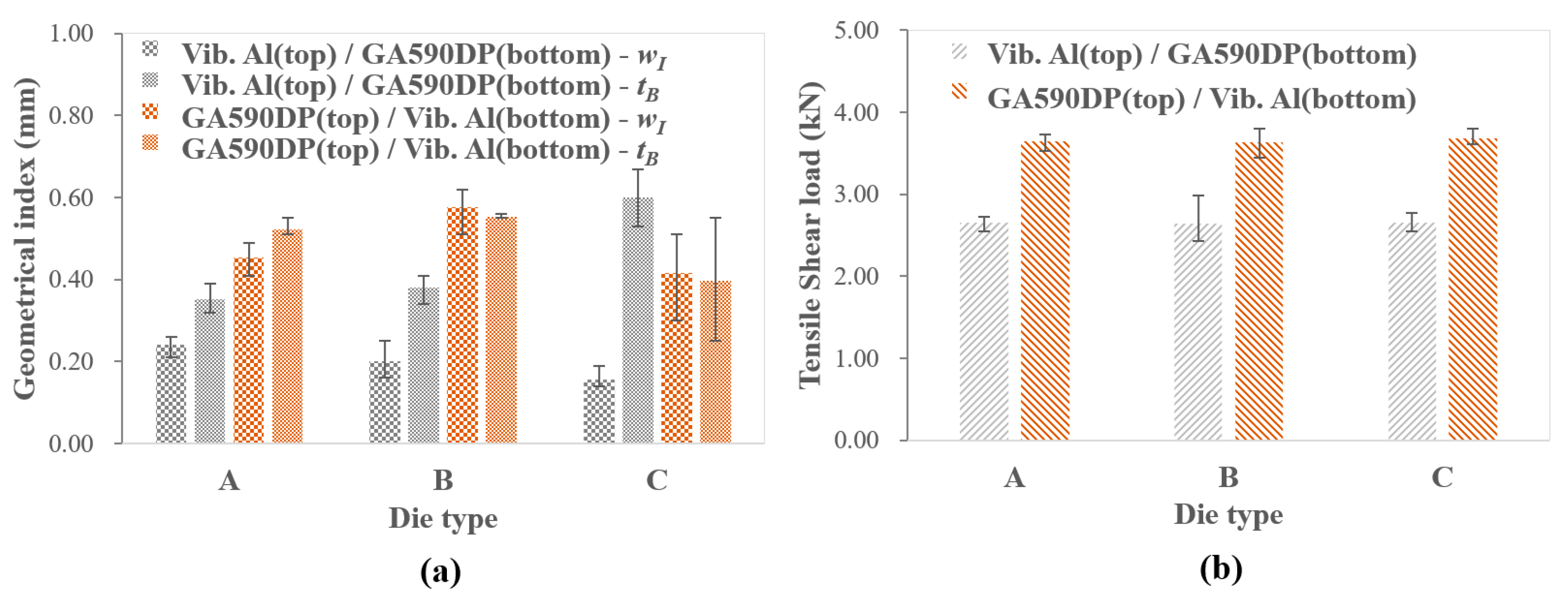
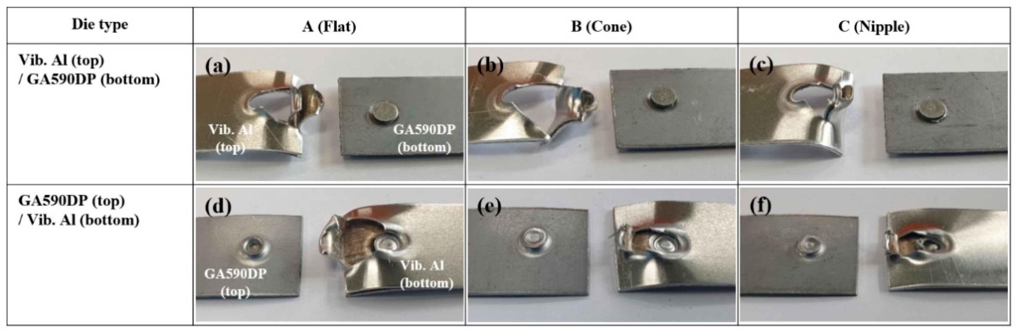
3.2. Self-Piercing Riveted Joint of Vibration-Damping Aluminum and GA590DP

In this section, the quality of the self-piercing riveted joint formed between vibration-damping Al and GA590DP is investigated. The cross-sectional views of the joints between the two materials are shown in Figure 9. Similarly to the previous section, three different types of die profiles (types A, B, and C), as shown in Figure 3, and two different panel configurations (vibration-damping Al on top and GA590DP on the bottom, and vice versa), were used to form the joints. The figure shows that when the vibration-damping Al panel is on top ((a), (b), and (c)), good top panel penetration of the rivet is observed with minimal gaps between the two sheets comprising the vibration-damping Al. The figure also shows that marginal gaps are present within the top seal regardless of the die type used. When the vibration-damping Al panel is on the bottom ((d), (e), and (f)), the results show cavity formations between the rivet and the top GA590DP panel. The formation of a cavity is a common phenomenon when the top steel panel is riveted with a bottom aluminum panel, since higher-strength steel undergoes an inadequate amount of plastic deformation during the riveting process to completely fill the rivet head. The results show that the cavity can be reduced by using a protruded die; for example, a larger cavity is formed for the flat die type (d) while the size of the cavity is successively reduced as the protrusions become larger, as seen from (e) and (f). Nevertheless, the presence of cavities, as shown in the next paragraph, does not affect the strength of the joint. The cross-sections also reveal relatively large gaps within the top and bottom seals, which are especially evident in (d) and (f).
The geometrical indexes (wI and tB) were measured for the joints, and the results are shown in Figure 10a. The figure shows that when the vibration-damping Al panel was positioned on top, wI and tB were 0.16~0.24 mm and 0.35~0.60 mm, respectively. For the case when the vibration-damping Al panel was on the bottom, wI and tB were 0.42~0.58 mm and 0.40~0.55, respectively.
To investigate the strength of the joints, tensile shear tests were performed, and the results are shown in Figure 10b. The figure shows that when the vibration-damping Al was positioned on top, the tensile shear load was approximately 2.6 kN for all three types of dies, indicating that there are no significant differences in joint strengths within the margin of error. When the vibration-damping Al panel was positioned on the bottom, the tensile shear load increased to approximately 3.6 kN for all three types of dies. Again, this shows that there are no significant differences in the strengths between the joints formed using different die types, yet the joint strength consistently increases by approximately 1 kN when the steel plate is on top. Such results can be attributed to the fact that the latter joints have larger interlock widths, as shown in Figure 10a.
The failure modes of the tensile tests were investigated, and the results are shown in Figure 11. The figure shows that for the configuration where vibration-damping Al panels were on top, all of the joint failures showed “upper panel tearing” ((a), (b), and (c)). The results also indicate that since the failure was due to the vibration-damping Al tearing, the tensile shear strength does not depend on the interlock width (during the failure, the riveted joints were intact). When the vibration-damping Al panels were positioned on the bottom, all of the joint failures showed “rivet pull-out” and “bottom sheet upper skin shear-out” ((d), (e), and (f)). In this case, the tensile shear loads were irrelevant to the interlock width since the failure of the joints was due to the bottom panel tearing. It is worthwhile to discuss the reason behind the higher shear strength associated with the steel panel positioned on top. The analysis of the failure mode shows that when the vibration-damping Al panel is on top, the tear-out begins at the top panel where the rivet pierces the material. Such a result indicates that the force at that location is mostly uniaxial. When the vibration-damping Al panel is on the bottom, however, the failure begins at the upper skin, which tears the Al panel due to the shear forces and eventually leads to “rivet pull-out” failure. This type of failure reflects that the force at the interface between the rivet and the Al panel is biaxial. The distribution of the force in two directions could be the reason behind the difference in shear load strength for the different panel placement configurations.

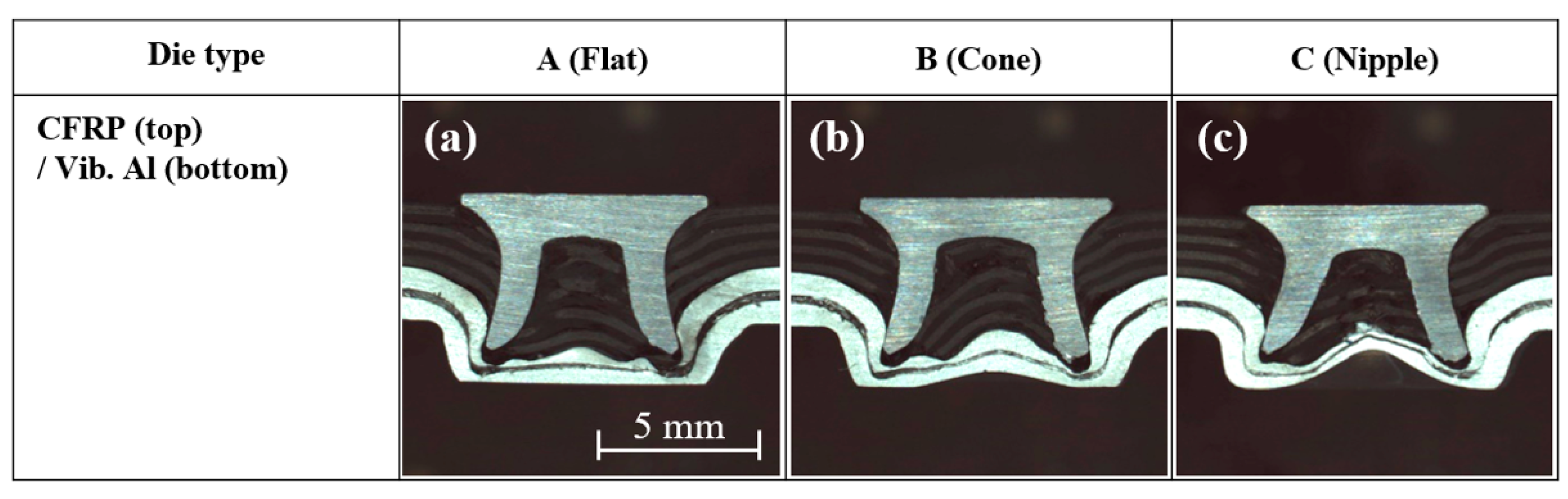
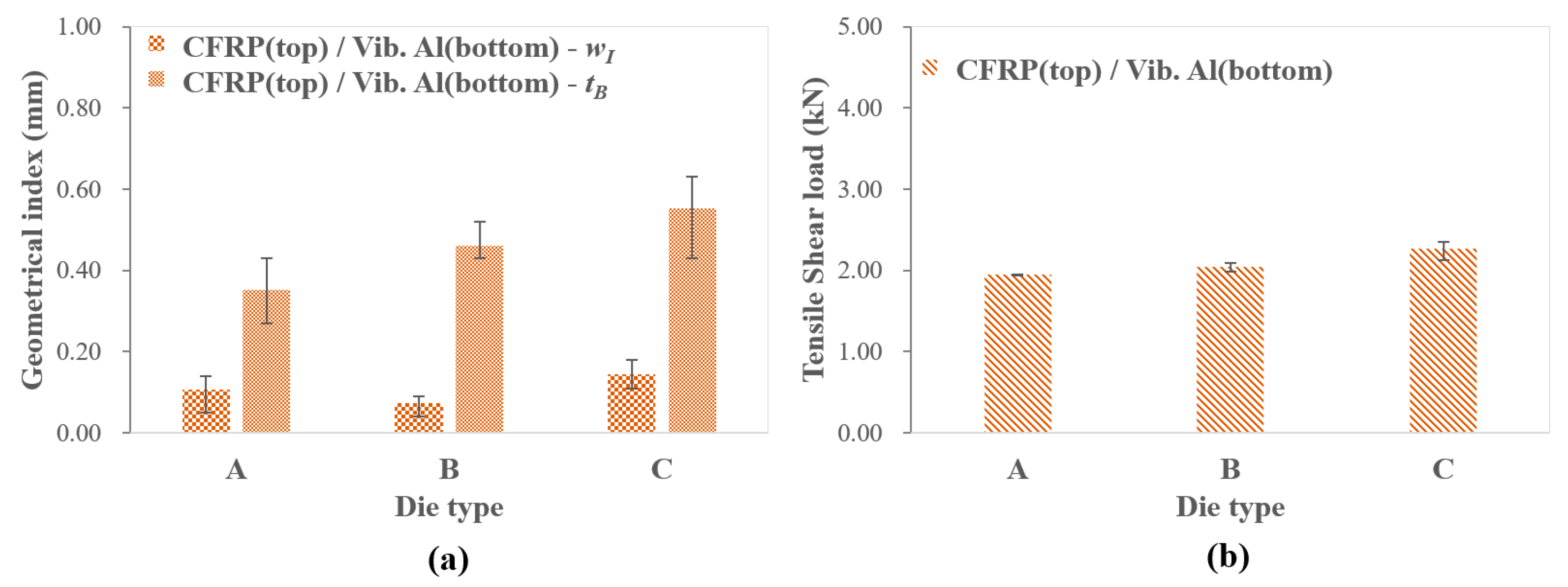
3.3. Self-Piercing Riveted Joint of Vibration-Damping Aluminum and CFRP

In this section, the quality of self-piercing riveted joints formed between vibration-damping Al and thermoset CFRP are investigated. Unlike other metals, the CFRP panel could not be positioned on the bottom during the SPR process due to a lack of the ductility required for the material to deform and establish an interlock. The cross-sectional views of the joints between the two materials are shown in Figure 12. The figure shows that the rivet pierces the CFRP panel and forms an interlock with the upper sheet of the vibration-damping Al panel. However, the bottom Al sheet is joined only by the existing adhesive between the two Al sheets. The figures show that cracks within the CFRP are present near the rivet head, which could have an adverse effect on the fatigue performance under cyclic loading [27,28]. Additionally, non-uniform contacts between the rivet legs and the Al sheets are shown, resulting from an uneven deformation of CFRP within the rivet shank cavity.
The measured geometrical indexes are shown in Figure 13a for the joints between CFRP and the vibration-damping Al panel. The results show that the interlock widths are relatively small compared with the joints formed using other materials, while the bottom depths are maintained at an acceptable value. To investigate the joint strength, the tensile shear loads were measured, and the results are shown in Figure 13b. As shown in the figure, a maximum tensile load of 2.26 kN was obtained for the joint formed using die type C, while tensile loads of 1.95 kN and 2.04 kN were obtained for the joint formed using die types A and B, respectively. The joint with the highest interlock width (namely, the joint formed using die type C) showed the highest tensile shear load but does not conform to the automotive joint standards. Finally, the failure modes of the tested joints were examined, and the results are presented in Figure 14. The figure shows that all of the joints show “rivet pull-out failure”, and no bottom cracks were observed.

4. Conclusions

This paper investigates self-piercing riveted joints between a vibration-damping Al panel and other dissimilar materials (aluminum alloy AL5052-H32, steel alloy GA590DP, and thermoset CFRP) by examining the joint cross-section quality, the geometrical features, the mechanical performance, and the failure modes. The following conclusions can be made:
  • When joining the vibration-damping Al panel with AL5052-H23 using the SPR process, the vibration-damping Al panel on top and die type C (nipple) showed the best cross-sectional characteristics and the maximum tensile shear strength.
  • When joining the vibration-damping Al panel with GA590DP using the SPR process, the vibration-damping Al panel on the bottom showed the best cross-sectional characteristics regardless of the die type. It was found that, due to the high strength of the steel alloy, cavities are formed inside the rivet when the GA590DP panel is on top, but they do not affect the joining strength between the two materials.
  • When joining the vibration-damping Al panel with CFRP using the SPR process, CFRP must be on top for the successful formation of the joint. The inhomogeneous and brittle characteristics of the CFRP result in an ununiform interface between the rivet and the top panel, and significant cracking can be observed within the rivet head.
In summary, the study of joining processes of dissimilar materials is becoming more and more critical as the manufacturing industry moves to highly advanced and environmentally friendly processes that integrate novel multi-materials. We hope that this analysis informs other researchers about the strength of the joints formed through an SPR process using various dissimilar materials.

Author Contributions

Conceptualization, D.H.K.; Methodology, T.E.J.; Formal Analysis, D.H.K.; Investigation, T.E.J. and D.H.K.; Resources, D.H.K.; Data Curation, J.K.; Writing—Original Draft Preparation, J.K.; Writing—Review & Editing, J.K.; Visualization, T.E.J.; Supervision, D.H.K. All authors have read and agreed to the published version of the manuscript.

Funding

The authors thank the following agencies for their support: the Korea Institute of Industrial Technology and the Industry Core Technology Development Program funded by the Ministry of Trade, Industry & Energy (Korea) (No. 10063579, 2015R1A6A1A03031833), and the Hongik University new faculty research support fund (2015).

Conflicts of Interest

The authors declare no conflict of interest.

References

  1. Haque, R. Quality of self-piercing riveting (SPR) joints from cross-sectional perspective: A review. Arch. Civ. Mech. Eng. 2018, 18, 83–93. [Google Scholar] [CrossRef]
  2. Blacket, S. Self-pierce riveting technology. A joining solution for light metals. In Proceedings of the 1st International Light Metals Technology Conference, Brisbane, Australia, 18–20 September 2003; pp. 383–388. [Google Scholar]
  3. He, X.; Deng, C.; Zhang, X. Fretting behavior of SPR joining dissimilar sheets of titanium and copper alloys. Metals 2016, 6, 312. [Google Scholar] [CrossRef] [Green Version]
  4. Briskham, P.; Blundell, N.; Han, L.; Hewitt, R.; Young, K. Comparison of self-pierce riveting, resistance spot welding and spot friction joining for aluminium automotive sheet for static strength. SAE Int. 2006, 2006-01-0774. [Google Scholar] [CrossRef] [Green Version]
  5. Special Fasteners. 2017. Available online: http://www.boellhoff.de (accessed on 1 July 2020).
  6. Franco, G.D.; Fratini, L.; Pasta, A.; Ruisi, V.F. On the self-piercing riveting of aluminium blanks and carbon fibre composite panels. Int. J. Mater. Form. 2013, 6, 137–144. [Google Scholar] [CrossRef]
  7. Jeon, N.-K.; Jeong, T.-E.; Rhee, S.; Kam, D.-H. Evaluation of CFRP/Steel/Aluminum three layer joining with self-piercing rivet. J. Weld. Join. 2019, 37, 56. [Google Scholar] [CrossRef] [Green Version]
  8. Jeon, N.-K.; Rhee, S.; Kam, D.-H. Parametric Study of Self-Piercing Riveting for CFRP-Aluminum Dissimilar Joint. J. Weld. Join. 2018, 36, 8. [Google Scholar] [CrossRef] [Green Version]
  9. Zhang, X.; He, X.; Xing, B.; Zhao, L.; Lu, Y.; Gu, F.; Ball, A. Influence of heat treatment on fatigue performances for self-piercing riveting similar and dissimilar titanium, aluminium and copper alloys. Mater. Des. 2017, 97, 108–117. [Google Scholar] [CrossRef] [Green Version]
  10. Zhao, L.; He, X.; Xing, B.; Lu, Y.; Gu, F.; Ball, A. Influence of sheet thickness on fatigue behavior and fretting of self-piercing riveted joints in aluminum alloy 5052. Mater. Des. 2015, 87, 1010–1017. [Google Scholar] [CrossRef]
  11. Jeong, T.-E.; Kim, M.-G.; Rhee, S.; Kam, D.-H. Joint quality study of self-piercing riveted aluminum and steel joints depending on the thickness and strength of base metal. J. Weld. Join. 2019, 37, 212. [Google Scholar] [CrossRef]
  12. Haque, R. Residual Stress and Deformation in SPR Joints of High Strength Materials. Ph.D. Thesis, Swinburne University of Technology, Melbourne, Australia, 2014. [Google Scholar]
  13. Isenstadt, A.; German, J.; Bubna, P.; Wiseman, M.; Venkatakrishnan, U.; Abbasov, L.; Guillen, P.; Moroz, N.; Richman, D.; Kolwich, G. Lightweighting Technology Development and Trends in U.S. Passenger Vehicles; Working Paper; ICCT: San Francisco, CA, USA, 2016; pp. 1–24. Available online: https://theicct.org/sites/default/files/publications/ICCT_PVtech_lightweighting_wp2016-25.pdf (accessed on 1 July 2020).
  14. Mascarin, A.; Hannibal, T.; Raghunathan, A.; Ivanic, Z.; Francfort, J. Vehicle lightweighting: 40% and 45% weight savings analysis: Technical cost modeling for vehicle lightweighting, INL/EXT-14-33863. 2015. Available online: https://inldigitallibrary.inl.gov/sites/sti/sti/6492855.pdf (accessed on 1 July 2020).
  15. Pramanik, A.; Basak, A.K.; Dong, Y.; Sarker, P.K.; Uddin, M.S.; Littlefair, G.; Dixit, A.R.; Chattopadhyaya, S. Joining of carbon fibre reinforced polymer (CFRP) composites and aluminium alloys—A review. Compos. Part A 2017, 101, 1–29. [Google Scholar] [CrossRef] [Green Version]
  16. Huang, Z.C.; Zhou, Z.J.; Huang, W. Mechanical behaviors of self-piercing riveting joining dissimilar sheets. Adv. Mater. Res. 2010, 97, 3932–3935. [Google Scholar] [CrossRef]
  17. Haque, R.; Durandet, Y. Investigation of self-pierce riveting (SPR) process data and specific joining events. J. Manuf. Process. 2017, 30, 148–160. [Google Scholar] [CrossRef]
  18. Eshtayeh, M.M.; Hrairi, M.; Mohiuddin, A.K.M. Clinching process for joining dissimilar materials: State of the art. Int. J. Adv. Manuf. Technol. 2016, 82, 179–195. [Google Scholar] [CrossRef]
  19. Mucha, J. The analysis of lock forming mechanism in the clinching joint. Mater. Des. 2011, 32, 4943–4954. [Google Scholar] [CrossRef]
  20. Hong, S.H.; Yan, F.; Sung, S.J.; Pan, J.; Su, X.; Friedman, P. Investigation of failure mode and fatigue behavior of flow drill screw joints in lap-shear specimens of aluminum 6082-T6 sheets. SAE Int. J. Mater. Manuf. 2016, 9, 746–750. [Google Scholar] [CrossRef] [Green Version]
  21. He, X.; Pearson, I.; Young, K. Self-pierce riveting for sheet materials: State of the art. J. Mater. Process. Technol. 2008, 199, 27–36. [Google Scholar] [CrossRef]
  22. Ma, Y.W.; Lou, M.; Li, Y.B.; Lin, Z.Q. Effect of rivet and die on self-piercing rivetability of AA6061-T6 and mild steel CR4 of different gauges. J. Mater. Process. Technol. 2018, 251, 282–294. [Google Scholar] [CrossRef]
  23. Abe, Y.; Kato, T.; Mori, K. Joinability of aluminium alloy and mild steel sheets by self-piercing rivet. J. Mater. Process. Technol. 2006, 177, 417–421. [Google Scholar] [CrossRef]
  24. Han, L.; Chrysanthou, A.; Young, K.W. Mechanical behaviour of self-piercing riveted multi-layer joints under different specimen configurations. Mater. Des. 2007, 28, 2024–2033. [Google Scholar] [CrossRef]
  25. Wood, P.K.C.; Schley, C.A.; Williams, M.A.; Rusinek, A. A model to describe the high rate performance of self-piercing riveted joints in sheet aluminum. Mater. Des. 2011, 32, 2246–2259. [Google Scholar] [CrossRef]
  26. Kam, D.-H.; Jeong, T.-E.; Kim, M.-G.; Shin, J. Self-piercing riveted joint of vibration-damping steel and aluminum alloy. Appl. Sci. 2019, 9, 4575. [Google Scholar] [CrossRef] [Green Version]
  27. Saleem, M.; Zitoune, R.; Sawi, I.E.; Bougherara, H. Role of the surface quality on the mechanical behavior of CFRP bolted composite joints. Int. J. Fatigue 2015, 80, 246. [Google Scholar] [CrossRef]
  28. Haeger, A.; Grudenik, M.; Hoffmann, M.J.; Knoblauch, V. Effect of drilling-induced damage on the open hole flexural fatigue of carbon/epoxy composites. Compos. Struct. 2019, 215, 238. [Google Scholar] [CrossRef]
Figure 1. Vibration-damping aluminum (Al) panel cross-sectional view under an optical microscope.
Applsci 10 05947 g001
Figure 2. Geometric dimensions of the rivet used in this study.
Applsci 10 05947 g002
Figure 3. The geometric details of the die types used in the self-piercing riveting (SPR) process.
Applsci 10 05947 g003
Figure 4. Geometrical indexes and the seals of a self-piercing riveted joint.
Applsci 10 05947 g004
Figure 5. The dimensions of the test sample used for the tensile-shear test (KS B ISO 14273).
Applsci 10 05947 g005
Figure 6. Cross-sectional images of the self-piercing riveted joint between vibration-damping Al and Al5052-H32 with respect to die types and configuration of the panels: (a,d) die type A, (b,e) die type B, and (c,f) die type C.
Applsci 10 05947 g006
Figure 7. (a) The interlock width and the bottom thickness, and (b) tensile shear loads for the self-piercing riveted joint between vibration-damping Al and Al5052-H32 with respect to die types.
Applsci 10 05947 g007
Figure 8. Failure modes of self-piercing riveted joints formed between vibration-damping Al and Al5052-H32 with respect to the die types and the panel configuration: (a,d) die type A, (b,e) die type B, and (c,f) die type C.
Applsci 10 05947 g008
Figure 9. Cross-sectional images for the self-piercing riveted joint formed between the vibration-damping Al and GA590DP with respect to SPR die type and panel configuration: (a,d) die type A, (b,e) die type B, and (c,f) die type C.
Applsci 10 05947 g009
Figure 10. (a) The interlock width and the bottom thickness, and (b) the tensile shear loads of the self-piercing riveted joint formed between vibration-damping Al and GA590DP with respect to the die type and the panel configuration.
Applsci 10 05947 g010
Figure 11. Failure modes of the self-piercing riveted joint formed between vibration-damping Al and GA590DP with respect to the die type and the panel configuration: (a,d) die type A, (b,e) die type B, and (c,f) die type C. The bottom side of the top panel is shown for (df).
Applsci 10 05947 g011
Figure 12. Cross-sectional images of a self-piercing riveted joint formed between vibration-damping Al and CFRP with respect to the die types: (a) die type A, (b) die type B, and (c) die type C.
Applsci 10 05947 g012
Figure 13. (a) Interlock width and bottom thickness, and (b) tensile shear loads for the self-piercing riveted joint formed between vibration-damping Al and CFRP with respect to the die type.
Applsci 10 05947 g013
Figure 14. Failure modes for the self-piercing riveted joint formed between vibration-damping Al and CFRP with respect to the die type: (a) die type A, (b) die type B, and (c) die type C.
Applsci 10 05947 g014
Table 1. The ultimate tensile strength and thickness of the materials tested here. The results for three different directions (0°, 45°, and 90°) are shown for carbon-reinforced plastic (CFRP).
Panel MaterialUltimate Tensile Strength (MPa)Thickness (mm)
Vibration-damping Al1881.44
Al5052-H322331.5
GA590DP6091.4
CFRP1032 (0°)/234 (45°)/1014 (90°)1.8

