Article

A Novel Kinematic Directional Index for Industrial Serial Manipulators

by
Giovanni Boschetti
Department of Management and Engineering, University of Padova, 36100 Vicenza, Italy
Appl. Sci. 2020, 10(17), 5953; https://doi.org/10.3390/app10175953
Submission received: 25 July 2020 / Revised: 24 August 2020 / Accepted: 26 August 2020 / Published: 27 August 2020
(This article belongs to the Special Issue Modelling and Control of Mechatronic and Robotic Systems)

Abstract

:
In the last forty years, performance evaluations have been conducted to evaluate the behavior of industrial manipulators throughout the workspace. The information gathered from these evaluations describes the performances of robots from different points of view. In this paper, a novel method is proposed for evaluating the maximum speed that a serial robot can reach with respect to both the position of the robot and its direction of motion. This approach, called Kinematic Directional Index (KDI), was applied to a Selective Compliance Assembly Robot Arm (SCARA) robot and an articulated robot with six degrees of freedom to outline their performances. The results of the experimental tests performed on these manipulators prove the effectiveness of the proposed index.

1. Introduction

Performance evaluation can provide useful information in the design of robots. For this reason, the first performance indexes were introduced as early as 1982. Manipulability [1], condition number [2], minimum singular value, kinematic isotropy [3], conditioning indexes [4] and dexterity analyses [5] provide a variety of information about a robot’s performance throughout its workspace. Manipulability allows the robot to be kept far from the kinematic singularity while the condition number (and usually its reverse) is used to achieve a fast measurement of the workspace isotropy, i.e., the ratio between the maximum and the minimum performance of the robot.
These indexes, as with many others, are based on the Jacobian matrix of the velocity kinematic problem. The use of these approaches brought up some problems [6] that have been resolved with the evolution of these methods.
A modern performance index must provide information in a summarized form, such as a value, on the behavior that the manipulator can have in each position that it can reach within its workspace. The key features for a performance index are:
  • To be homogeneous/independent of the unit of measurement [7,8,9,10,11,12].
  • To be independent of the reference system [13,14].
  • Providing increasingly accurate information [15,16,17,18].
A first sample of homogeneous indexes has been proposed in [7], where the main concept consists of directly relating the Cartesian and the actuator velocities. Another approach suggested introducing a novel dimensionally homogeneous Jacobian matrix [8]. In these methods, the velocities of three points of the flange have been considered and related with the motor velocities. A different approach was proposed in [10] where a proper performance index was developed to gather interesting information on a robot’s behavior using a non-homogeneous Jacobian matrix.
An interesting approach was proposed in [13,14], where a motion/force transmission index was introduced. In these works, the use of proper virtual coefficients instead of the Jacobian matrix allowed introducing a frame-free performance index. This means that the evaluation is completely independent from the choice of the absolute reference frame in which it is computed.
Recent performance indexes [15,16,17,18] give more information compared to previous ones and are usually not affected by the adopted units of measurement and the choice of the reference frame.
Once a performance index can guarantee the above-mentioned features, it can be adopted for several purposes. In recent years, performance evaluation has been mainly conducted for the following uses:
  • Optimization of manipulator design [19,20,21].
  • Comparison between different robot architectures [22,23].
  • Optimization of robot trajectory planning [24,25,26,27].
  • Optimization of task locating (or robot positioning) [28,29].
The proposed performance index has been conceived to give useful information for the latter issue, i.e., finding the best location for a generic task, given the direction of the robot’s main movements. The first performance index that took the direction of motion into account with respect to the actuator’s movements was introduced in [30] and extended in [28]. Such an index, called a directional selective index (DSI), gives accurate information about the performance of parallel robots and allows finding the regions of the workspace where a parallel robot achieves its maximum and minimum performance. However, the DSI formulation cannot be easily extended to serial robots. For this reason, a novel approach, called the kinematic directional index (KDI), has been introduced in this paper. This method allows analyzing the behavior of a serial robot, taking into account the position of the robot and the direction of motion. As such, the index can be adopted for several purposes. In this paper, a performance analysis will be performed, by means of KDI, with two main goals:
  • Finding the direction of maximum velocity with respect to a point.
  • Finding the area of maximum velocity with respect to a direction of interest.
These two main analyses can provide very useful information for robot programming and the definition of the trajectory planning of industrial tasks. Performing the movements along the suggested directions can drastically reduce the time taken to complete a task.
The main motivations for this work are:
  • Defining the novel KDI.
  • Presenting two applications of the KDI.
  • Proving the effectiveness of the KDI by exploiting two industrial robots.
The paper is organized as follows: in Section 2, the KDI is defined and formulated. In Section 3, two robots are presented for KDI computation and for the experimental tests. In the first part of Section 4, the KDI is computed at a point in the workspace in any direction of the horizontal plane, while in the second part, the index is computed along a direction of interest in the whole horizontal plane. In Section 5, the robot performances have been verified experimentally and are compared with the KDI. The strong correlation between the KDI values and the experimental results proves the effectiveness of the proposed index. Finally, in Section 6, the conclusions are addressed, and further research directions are given.

2. The KDI Performance Index

The KDI performance index allows evaluating the behavior of a serial manipulator in terms of linear velocity. For this purpose, the serial robot’s kinematics are considered. As mentioned above, this index is based on the analysis of the Jacobian matrix J . As such, the analyzed problem can be identified by the forward velocity kinematic equation defined in Equation (1):
x ˙ = J q ˙
where x ˙ and q ˙ are the velocity vectors in the Cartesian space and the joint space, respectively.
Since the KDI aims to determine the region in which a robot reaches its maximum translational velocity, only the translational part of the Jacobian matrix has been considered; hence, the motion of the wrist and its motors are not taken into account.
Once the direction of interest (i.e., the direction of motion) is defined, the velocities along the axes that are normal for the direction of interest are set as null values. Without loss of generality, it is possible to consider the direction of interest along the x-axis, and the velocity in this direction can be defined as follows in Equation (2):
x ˙ 0 = j 1 , 1 j 1 , 2 j 1 , m j n , 1 j n , 2 j n , m q ˙ 1 q ˙ m
where n is the number of degrees of freedom in the Cartesian space and m is the number of actuators that defines the joint space.
Let us define R as the rotation matrix that aligns the x-axis to the direction of interest (d), JR as the Jacobian matrix rotated by the matrix R, and d ˙ as the speed along d. In this way, in Equation (3), the velocity along the direction of interest is identified.
d ˙ 0 = r 1 , 1 r 1 , n r n , 1 r n , n j 1 , 1 j 1 , 2 j 1 , m j n , 1 j n , 2 j n , m q ˙ 1 q ˙ m = j R   1 , 1 j R   1 , 2 j R   1 , m j R   n , 1 j R   n , 2 j R   n , m q ˙ 1 q ˙ m
The value of KDI is identified by the letter K and is defined as the maximum value taken by d ˙ as highlighted in Equation (4):
K = max d ˙
When a robot moves at its maximum speed, some joint motors are also working at their maximum speed. Since Equation (3) is a linear system, it is possible to state that the minimum number of motors in this condition is equal to m – n + 1. For example, a solution can be found by means of a linear programming problem. However, most industrial robots are non-redundant, so a proper solution for these robots is proposed in detail. In this case, the number of degrees of freedom (n) is equal to the number of motors (m) (n = m). Hence, the Jacobian matrix is a square matrix as defined in Equation (5).
d ˙ 0 = j R   1 , 1 j R   1 , n j R   n , 1 j R   n , n q ˙ 1 q ˙ n
It is important to highlight that the maximum velocity in the direction of interest is achieved when at least one motor reaches its maximum velocity. Therefore, in order to find the solution to this problem, the velocity in the direction of interest ( d ˙ ) can be set to a fictitious value of “1” and the fictitious motor velocities can be easily computed since the following problem is defined by a linear system (Equation (6)) where the number of unknowns is equal to the number of equations.
1 0 = J R q ˙ 1 q ˙ n
The motor that limits the robot’s performance is that which is nearest to its maximum velocity. In order to easily find this motor (p) and its ratio with respect to its maximum velocity, let us define, by means of Equation (7), the maximum value achieved by the ratios between each joint speed and its maximum.
1 K = q ˙ p q ˙ p , m a x = max q ˙ 1 q ˙ 1 , m a x ,   , q ˙ n q ˙ n , m a x
1/K is the maximum ratio between a joint speed and its maximum velocity, and this value is given by the joint p whose speed is the nearest to its maximum. This value can be also greater than 1, which can only happen because the solution to the problem is proposed using fictitious velocities. Nevertheless, this eventuality will not affect the validity of the solution.
Here, K identifies the KDI and also the maximum velocity that the robot can reach in the chosen direction of interest. This can be easily understood multiplying the velocities of Equation (5) by K and achieving Equation (8).
K 0 = J R K q ˙ 1 K q ˙ n
The value of K represents the maximum velocity of the robot, since K q ˙ p is equal to the maximum value ( q ˙ p , m a x ,), while the velocities of the other joints are below their maximum values.
From the definition of the KDI, it is possible to observe that it is not affected by the choice of the unit of measurement since only the value of K is used to compare the performances at different points in the workspace. Moreover, the index is also “frame free” because it does not depend on the use of an absolute reference frame but only on the robot configuration and on the direction of interest.

3. System Layout for KDI Validation
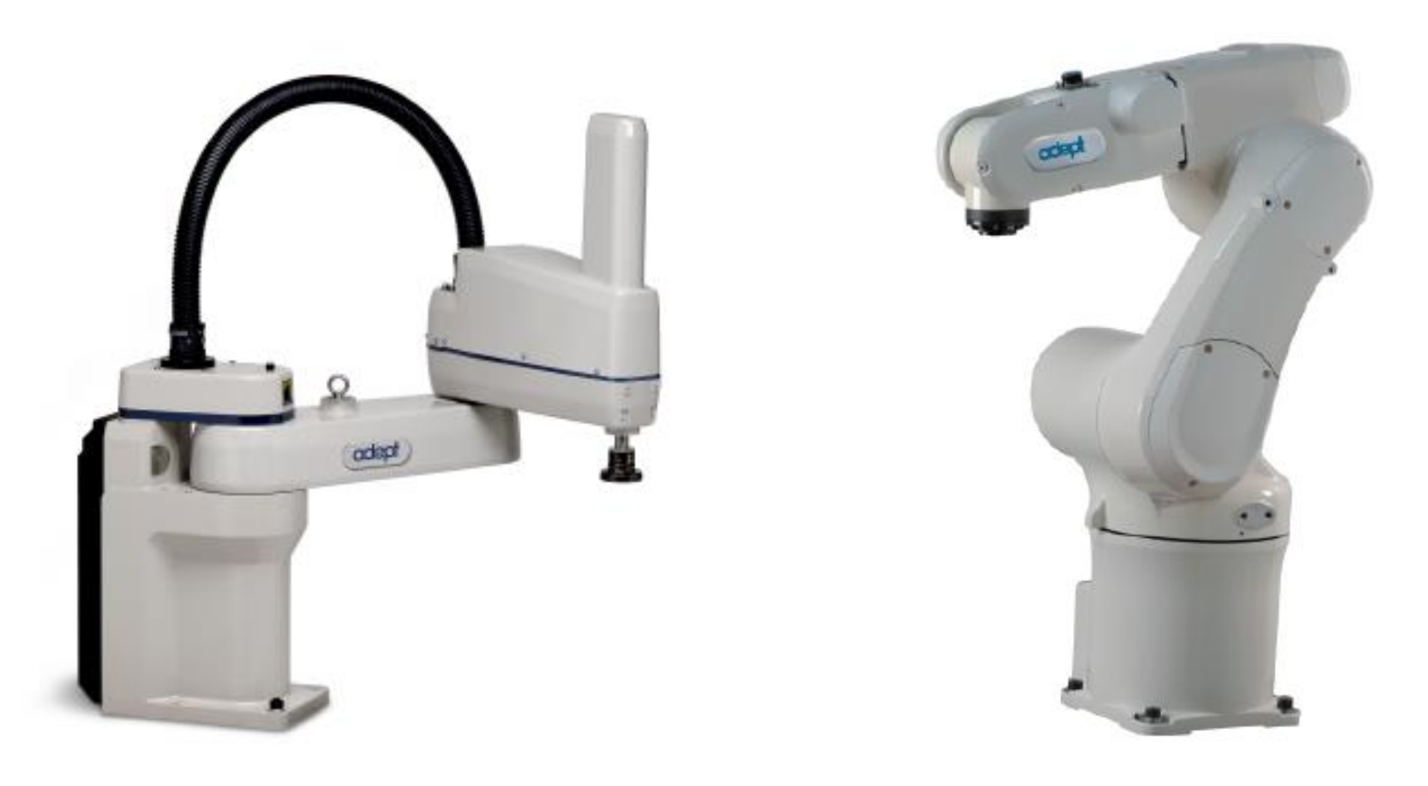
Two industrial manipulators were chosen to verify the accuracy of the KDI: an Adept Cobra 600 and an Adept Viper 650 robots (manufactured by Adept Technology, Pleasanton, CA, USA). This choice was made by looking for the most common kinematic architectures for serial robots. The first robot is a Selective Compliance Assembly Robot Arm (SCARA), while the second one is an articulated robot with six degrees of freedom (see Figure 1). In the SCARA robot, the index is used only in the horizontal plane since the vertical movements depend only on a prismatic joint whose performance does not change throughout the workspace; in the second case, the index can be useful along any direction of the workspace. However, in order to achieve comparable results, the performance of the articulated robot will also be investigated in a horizontal plane.

3.1. SCARA Robot

The first test was performed on a horizontal plane by means of a SCARA robot. The horizontal movements depended on the motion of the first two links as represented in Figure 2, where the first two links are depicted in blue, and their reference frames are represented in violet together with the absolute frame.
In Table 1, the complete Denavit Hartenberg table is defined in order to highlight the terms that are used for the computation of the Jacobian matrix of this robot.
The projection in the horizontal plane of a SCARA manipulator allows highlighting the lengths of the two main links: L 1 = 325   mm and L 2 = 275   mm . The end-effector horizontal speed is given in function of the actuator speeds by means of the Jacobian matrix defined in Equation (9).
J S = z 1 × O F O 1 z 2 × O F O 2
In this case, it is possible to easily calculate the Jacobian Matrix as follows in Equation (10):
J S =   L 1 sin θ 1 L 2   sin θ 1 , 2 L 2   sin θ 2 L 1 cos θ 1 + L 2   cos θ 1 , 2 L 2   cos θ 2
where the expression θ i , j = θ i + θ j has been used.

3.2. Articulated Robot

Figure 3 depicts the kinematic scheme of the articulated robot, without taking its wrist into account. The links that are involved in the translation of the wrist center are depicted in blue and their reference frames are represented in violet together with the absolute frame. The origin of the wrist is also highlighted (OF). In Table 2, all the kinematic parameters are highlighted by means of the Denavit Hartenberg table.
Where the lengths of the links are L 1 =   270   m m   and L 2 =   295   mm , while the non-null offset between the kinematic axes are a 1 =   75   mm and a 3 =   90   mm .
Using these parameters, the Jacobian matrix of Equation (11) can be computed at each point of the workspace.
J A = z 1 × O F O 1 z 2 × O F O 2 z 3 × O F O 3
This Jacobian matrix relates the velocity of the wrist center with the ones of the joints.

4. Performance Investigation

Given the proper Jacobian matrix, it is possible to compute the KDI in any point of the workspace and in any direction. To highlight the usefulness of the KDI, two different performance investigations were proposed. The first one consisted of finding the maximum velocity that the robot can reach in a point for each direction of motion. The second one pointed out the areas where the robot reached its maximum velocity with respect to a direction of interest.

4.1. Performance Investigation in a Point

Without loss of generality, the KDI for a SCARA robot is plotted at the point P (350, 150) along any direction of the horizontal plane (see Figure 4). The performance along the x-axis is highlighted with a red line.
As mentioned above, when the maximum speed along any direction of a robot is achieved, at least one motor reaches its maximum speed. Therefore, given a generic point of the workspace, if this type of information is needed, the computation of the KDI can be greatly simplified. In fact, the maximum speed (absolute or relative) is reached when both motors reach their maximum (or minimum) speed. As such, the directions of the maximum Cartesian speed can be calculated by using a proper matrix that contains the four possible combinations of maximum and minimum speed. By multiplying such a matrix with the Jacobian matrix, the maximum speed direction can be identified by Equation (12).
P = J S q ˙ 1 , m a x q ˙ 1 , m a x q ˙ 1 , m a x q ˙ 1 , m a x q ˙ 2 , m a x q ˙ 2 , m a x q ˙ 2 , m a x q ˙ 2 , m a x
where P is a matrix made up of the four virtual points that represent the vertexes of the parallelogram that delimits the robot speed in the horizontal plane as depicted in Figure 4.
By following the same approach with the articulated robot, the maximum and minimum values of the three joint speeds allowed defining the eight vertexes of a cuboid as depicted in Figure 5. Given these vertexes, the maximum speed of the robot could be gathered in any direction of the workspace. In Figure 5, for example, the performance of the robot along the x-axis is highlighted with a red line.

4.2. Performance Investigation in the Workspace

As mentioned above, the performance was evaluated in a horizontal plane. For each robot, a proper set of points was defined, and a direction of interest was chosen. The SCARA set of points was given by nine points along any radial direction of the workspace with an angular step of ten degrees. Since the articulated robot was also investigated in a horizontal plane, the plane with the highest reach distance was chosen (i.e., where the wrist was at the same height as the shoulder). For this test, the set was given by seven points along any radial direction with an angular step of ten degrees. The points that are outside the workspace were considered. In Figure 6, the two sets of points are depicted together with the workspace limits.
For the SCARA robot, the KDI index was computed along the direction of the y-axis (i.e., with a rotation of 90 degrees about the z-axis by means of the matrix R). The KDI was computed for the articulated robot with a rotation of 45 degrees about the z-axis. The KDI was normalized and plotted in Figure 7 for both robots. The yellow areas indicate the regions where the robots achieved their best performance, while the blue areas show where the robots were slower.

5. Experimental Setup and Performance Analysis in the Workspace

In order to experimentally verify where the robots can achieve the maximum velocity, the end effector of each robot was equipped with an accelerometer, as shown in Figure 8. The chosen device was a piezometric accelerometer, DeltaTron Type 4508001 (manufactured by Hottinger Brüel & Kjær, Nærum, Denmark), which did not require additional hardware for signal conditioning. The data were acquired by means of an LMS Pimento analyzer (manufactured by LMS International, Leuven, Belgium) at an acquisition frequency of 1000 Hz. The software supplied with the analyzer allowed directly computing the speed of the investigated movements.
The experimental analysis was performed with the same set of points defined above and illustrated in Figure 6, in order to compare the results of the investigation with the values taken by the KDI. At each point, a back-and-forth movement with a length of 60 mm in the direction of interest was repeated five times so that the center of the displacement (where the maximum speed was reached) coincided with the investigated point. Using a data acquisition system, the signals of the accelerometers were gatherd, and the velocity of the robots was computed. In order to reduce the effect of measuring errors, the maximum experimentally measured speed was computed by calculating the average between the peaks of each repeated movement. In this way, the maximum speed reached in each point of the workspace could be collected. Such results have been normalized since the target of the work is to highlight the region of maximum speed without making performance comparisons between different robots. The experimentally gathered normalized performances are plotted in Figure 9 for both robots.
It is now possible to appreciate that the values of the KDI perfectly matched the behavior of the robots; the best performance region identified by the KDI has a good correspondence with the measured region. Moreover, the trend of performance given by the KDI met the speed variation throughout the workspace. In fact, the comparison between Figure 7 and Figure 9 highlights that the KDI can be adopted as a useful tool to foresee the regions where a robot can achieve its maximum speed with respect to a direction of interest. In order to better identify the correlation between the index and the real performance, the maximum value of the measured speed has been plotted in Figure 10 for each investigated point with respect to the value given by the KDI at the same point. Moreover, the linear regression between the KDI and the speed of each robot has been computed and plotted by means of a red line. In Figure 10, the proximity of the points on the scatter diagram to the red lines clearly shows a strong correlation with the KDI values of the robots’ velocities; therefore, it proves the effectiveness of the novel proposed index.

6. Conclusions

A novel performance index called the KDI has been proposed. This index is not affected by the non-homogeneous Jacobian matrix and does not depend on the choice of the units of measurement and on the position of the absolute reference frame. The index was computed for a SCARA robot and an articulated robot to analyze the behavior of the manipulators for two main purposes: finding the direction of maximum velocity with respect to a point, and finding the area of maximum velocity with respect to a direction of interest in the workspace. Being a fully kinematic index (i.e., it does not consider the dynamics and the control of the robots), it gives a high-quality description of the robot’s behavior, and the experimental tests demonstrate the effectiveness of the proposed index.
Future works can be addressed by following some steps: first, the use of the index for redundant manipulators will be investigated; second, the same reasoning will be followed to synthesize a dynamic performance index that is able to consider the direction of motion; afterwards, the use of these indexes for other issues, such as the optimal design of manipulators and/or robot trajectory planning, will be investigated.

Funding

This research received no external funding.

Conflicts of Interest

The author declares no conflict of interest.

References

  1. Yoshikawa, T. Manipulability of Robotic Mechanisms. Int. J. Robot. Res. 1985, 4, 3–9. [Google Scholar] [CrossRef]
  2. Salisbury, J.K.; Craig, J.J. Articulated hands: Force control and kinematic issues. Int. J. Robot. Res. 1982, 1, 4–17. [Google Scholar] [CrossRef]
  3. Angeles, J.; López-Cajún, C.S. Kinematic Isotropy and the Conditioning Index of Serial Robotic Manipulators. Int. J. Robot. Res. 1992, 11, 560–571. [Google Scholar] [CrossRef]
  4. Gosselin, C.; Angeles, J. A Global Performance Index for the Kinematic Optimization of Robotic Manipulators. J. Mech. Des. 1991, 113, 220–226. [Google Scholar] [CrossRef]
  5. Gao, F.; Liu, X.; Gruver, W.A. Performance evaluation of two-degree-of-freedom planar parallel robots. Mech. Mach. Theory 1998, 33, 661–668. [Google Scholar] [CrossRef]
  6. Merlet, J.P. Jacobian, Manipulability, Condition Number, and Accuracy of Parallel Robots. J. Mech. Des. 2005, 128, 199–206. [Google Scholar] [CrossRef]
  7. Gosselin, C. The optimum design of robotic manipulators using dexterity indices. Robot. Auton. Syst. 1992, 9, 213–226. [Google Scholar] [CrossRef]
  8. Kim, S.-G.; Ryu, J. New dimensionally homogeneous jacobian matrix formulation by three end-effector points for optimal design of parallel manipulators. IEEE Trans. Robot. Autom. 2003, 19, 731–737. [Google Scholar] [CrossRef]
  9. Kim, S.-G.; Ryu, J.-H. Force transmission analyses with dimensionally homogeneous Jacobian matrices for parallel manipulators. KSME Int. J. 2004, 18, 780–788. [Google Scholar] [CrossRef]
  10. Mansouri, I.; Ouali, M. A new homogeneous manipulability measure of robot manipulators, based on power concept. Mechatronics 2009, 19, 927–944. [Google Scholar] [CrossRef]
  11. Mansouri, I.; Ouali, M. The power manipulability – A new homogeneous performance index of robot manipulators. Robot. Comput. Manuf. 2011, 27, 434–449. [Google Scholar] [CrossRef]
  12. Cardou, P.; Bouchard, S.; Gosselin, C. Kinematic-Sensitivity Indicies for Dimensionally Nonhomogeneous Jacobian Matrices. IEEE Trans. Robot. 2010, 26, 166–173. [Google Scholar] [CrossRef]
  13. Wang, J.; Liu, X.; Wu, C. Optimal design of a new spatial 3-DOF parallel robot with respect to a frame-free index. Sci. China Ser. E: Technol. Sci. 2009, 52, 986–999. [Google Scholar] [CrossRef]
  14. Wang, J.; Wu, C.; Liu, X. Performance evaluation of parallel manipulators: Motion/force transmissibility and its index. Mech. Mach. Theory 2010, 45, 1462–1476. [Google Scholar] [CrossRef]
  15. Brinker, J.; Corves, B.; Takeda, Y. Kinematic performance evaluation of high-speed Delta parallel robots based on motion/force transmission indices. Mech. Mach. Theory 2018, 125, 111–125. [Google Scholar] [CrossRef]
  16. Wang, C.; Zhao, Y.; Dong, C.; Liu, Q.; Niu, W.; Liu, H.; Liu, H. Kinematic Performance Comparison of Two Parallel Kinematics Machines. In Advances in Mechanism and Machine Science. IFToMM WC 2019. Mechanisms and Machine Science; Uhl, T., Ed.; Springer: Cham, Switzerland, 2019; Volume 73. [Google Scholar]
  17. Boschetti, G.; Trevisani, A. Cable Robot Performance Evaluation by Wrench Exertion Capability. Robotics 2018, 7, 15. [Google Scholar] [CrossRef] [Green Version]
  18. La Mura, F.; Romanó, P.; Fiore, E.; Giberti, H. Workspace Limiting Strategy for 6 DOF Force Controlled PKMs Manipulating High Inertia Objects. Robotics 2018, 7, 10. [Google Scholar] [CrossRef] [Green Version]
  19. Wu, X. Performance Analysis and Optimum Design of a Redundant Planar Parallel Manipulator. Symmetry 2019, 11, 908. [Google Scholar] [CrossRef] [Green Version]
  20. Alvarado, R.R.; Castañeda, E.C. Optimum design of the reconfiguration system for a 6-degree-of-freedom parallel manipulator via motion/force transmission analysis. J. Mech. Sci. Technol. 2020, 34, 1339–1349. [Google Scholar] [CrossRef]
  21. Yu, G.; Wu, J.; Wang, L.; Gao, Y. Optimal Design of the Three-Degree-of-Freedom Parallel Manipulator in a Spray-Painting Equipment. Robotics 2019, 38, 1064–1081. [Google Scholar] [CrossRef]
  22. Wu, X.; Yan, R.; Xiang, Z.; Zheng, F.; Tan, R. Performance Analysis and Comparison of Three Planar Parallel Manipulators. Power Transm. 2019, 79, 270–279. [Google Scholar] [CrossRef]
  23. Baena, A.H.; Valdez, S.I.; Romero, F.D.J.T.; Montes, M.M. Comparison of Parallel Versions of SA and GA for Optimizing the Performance of a Robotic Manipulator. Power Transm. 2020, 86, 290–303. [Google Scholar] [CrossRef]
  24. Boschetti, G. A Picking Strategy for Circular Conveyor Tracking. J. Intell. Robot. Syst. 2016, 81, 241–255. [Google Scholar] [CrossRef]
  25. Bottin, M.; Rosati, G. Trajectory Optimization of a Redundant Serial Robot Using Cartesian via Points and Kinematic Decoupling. Robot. 2019, 8, 101. [Google Scholar] [CrossRef] [Green Version]
  26. Bottin, M.; Ceccarelli, M.; Morales-Cruz, C.; Rosati, G. Design and Operation Improvements for CADEL Cable-Driven Elbow Assisting Device. Mech. Mach. Sci. 2021, 91, 503–511. [Google Scholar]
  27. Bottin, M.; Rosati, G.; Boschetti, G. Working Cycle Sequence Optimization for Industrial Robots. Mech. Mach. Sci. 2021, 91, 228–236. [Google Scholar]
  28. Boschetti, G.; Rosa, R.; Trevisani, A. Optimal robot positioning using task-dependent and direction-selective performance indexes: General definitions and application to a parallel robot. Robot. Comput. Manuf. 2013, 29, 431–443. [Google Scholar] [CrossRef]
  29. Sharkawy, A.-N.; Papakonstantinou, C.; Papakostopoulos, V.; Moulianitis, V.; Aspragathos, N. Task Location for High Performance Human-Robot Collaboration. J. Intell. Robot. Syst. 2020, 1–20. [Google Scholar] [CrossRef]
  30. Boschetti, G.; Trevisani, A. Direction Selective Performance Index for Parallel Manipulators. In Proceedings of the First International Conference on Multibody System Dynamics IMSD 2010, Lappeenranta, Finland, 25–27 May 2010. [Google Scholar]
Figure 1. The Selective Compliance Assembly Robot Arm (SCARA) robot (left) and the articulated robot (right) exploited for the experimental validation of the Kinematic Directional Index (KDI) index.
Applsci 10 05953 g001
Figure 2. The kinematic scheme of the SCARA robot.
Applsci 10 05953 g002
Figure 3. The kinematic scheme of the articulated robot.
Applsci 10 05953 g003
Figure 4. KDI computed for the SCARA robot in point P (350, 150) along any horizontal direction.
Applsci 10 05953 g004
Figure 5. KDI computed for the articulated robot in point P (250, 300, 350) along any direction.
Applsci 10 05953 g005
Figure 6. Point sets in which the experimental analyses were performed for the SCARA robot (left) and the articulated robot (right).
Applsci 10 05953 g006
Figure 7. KDI computed for SCARA (left) and articulated (right) robots.
Applsci 10 05953 g007
Figure 8. The end effectors of the robots equipped with accelerometers.
Applsci 10 05953 g008
Figure 9. Normalized maximum speeds of the SCARA (left) and the articulated (right) robots.
Applsci 10 05953 g009
Figure 10. Scatter diagram of the KDI versus speeds for the SCARA (left) and articulated (right) robots.
Applsci 10 05953 g010
Table 1. Denavit Hartenberg table of the Selective Compliance Assembly Robot Arm (SCARA) robot.
i T i , i 1 α i 1 a i 1   θ i d i
1 T 1 , 0 0 0 θ 1 0
2 T 2 , 1 0 L 1 θ 2 0
3 T 3 , 2 π L 2 0 d 3
4 T 4 , 3 0 0 θ 4 0
Table 2. Denavit Hartenberg table of the articulated robot.
i T i , i 1 α i 1 a i 1   θ i d i
1 T 1 , 0 0 0 θ 1 0
2 T 2 , 1 π / 2 a 1 θ 2 0
3 T 3 , 2 0 L 1 θ 3 0
4 T 4 , 3 π / 2 a 3 θ 4 L 2
5 T 5 , 4 π / 2 0 θ 5 0
6 T 6 , 5 π / 2 0 θ 6 0

