Article

Advanced Hybrid Beamforming Technique in MU-MIMO Systems

1
Department of Information and Communication Engineering, Sejong University, Seoul 05006, Korea
2
Autonomous Intelligent Unmanned Flying Vehicles Institute, Sejong University, Seoul 05006, Korea
*
Author to whom correspondence should be addressed.
Appl. Sci. 2020, 10(17), 5961; https://doi.org/10.3390/app10175961
Submission received: 13 July 2020 / Revised: 12 August 2020 / Accepted: 27 August 2020 / Published: 28 August 2020
(This article belongs to the Section Electrical, Electronics and Communications Engineering)

Abstract

:
This paper proposes a high performance wireless commmunication technology in MU-MIMO systems. The millimeter wave (mmWave) communication technology was considered for the future wireless communication systems such as the fifth-generation new radio (5G NR). In 5G NR, the mmWave communication technology was studied to increase the use of wide bandwidth and the data rate. Therefore, MU-MIMO systems can be used in mmWave. To decrease the complexity of conventional digital beamforming system, the hybrid beamforming system was studied. In particular, the proposed hybrid beamforming system improves the error performance and average sum rate in partially connected structure (PCS) hybrid beamforming system. The proposed PCS hybrid beamforming system forms variously combined beam patterns using the information of azimuth and elevation angles for the multi-paths according to the number of bits. In addition, the azimuth and elevation angles among the formed beam patterns are estimated according to the received signal strength (RSS). In the simulation results, the proposed PCS hybrid beamforming system has better error performance and the average sum rate than the conventional hybrid beamforming system.

1. Introduction

The mmWave is capable of wide-band transmission and is used for various purposes such as satellite, mobile communication. The mmWave communication technology is attracting attention for high data rate in 5G NR [1,2,3,4,5,6]. Although signal absorption and path loss occur due to the propagation characteristics in mmWave frequencies, the data rate can be increased by using mmWave frequencies. In addition, due to the propagation characteristics of the short wavelength of the mmWave frequencies, the antenna size can be reduced in a hardware system to form a plurality of antenna arrays. Also, the antenna arrays can provide large antenna gains to compensate for the high path loss of the mmWave. Therefore, mmWave communication technology is selected as an important technology for 5G NR.
The fully digital beamforming system requires a separate radio frequency (RF) chain for each antenna. However, as the number of antennas increases, more RF chains are required. Therefore, the cost and the power consumption are increased. To reduce the cost and the power consumption, hybrid beamforming is constructed by concatenation of a low-dimensional digital beamformer and RF beamformer using phase shifters [7,8,9,10] is issued. Hybrid beamforming systems employ a fewer RF chains than conventional fully digital beamforming system. Therefore, efficient communication with low hardware complexity is possible. Hybrid beamforming systems include fully connected structure (FCS) and partially connected structure (PCS). FCS hybrid beamforming system is a structure which each RF chain is connected to all antennas to obtain high channel capacity. However, FCS hybrid beamforming system requires high complexity in a hardware system. To reduce the complexity of the FCS hybrid beamforming system, there is a PCS hybrid beamforming system with the same number of antennas connected to each RF chain. PCS hybrid beamforming system has low hardware complexity and performance degradation. Also, hybrid beamforming system based on codebook is considered in 5G NR. The hybrid beamforming system based on codebook selects the most suitable analog beam pattern with the channel status of each user in the codebook storing the predesigned analog beam patterns. To reduce the channel feedback overhead required in designing a hybrid beamformer using multiple antennas, the methods of selecting an analog beam within a predesigned codebook were proposed [11,12]. The hybrid beamforming system based on codebook is a realistic method and can be applied to 5G NR.
This paper proposes the improved PCS hybrid beamforming increasing the average sum rate, and the proposed technique can be used in any bands containing mmWave.
The technique of hybrid beamforming is not limited to only mmWave band which is larger than 6 GHz, and can be used at other bands in addition to mmWave band. However, the hybrid beamforming is suited well in the mmWave band compared to below 6 GHz since the hybrid beamforming was originally developed to use for realizing massive MIMO system. For practical massive MIMO system, mmWave band is required for various reasons such as small antenna size and less RF chains, etc. [13]. Therefore, all studies about the hybrid beamforming are based on mmWave band since massive systems are required for improving data rate or reliability.
Section 2 introduces the system models. Section 3 describes the conventional hybrid beamforming system. The proposed hybrid beamforming system is described in Section 4. In Section 5, the simulation results are illustrated to compare the error performance and the average sum rate. Section 6 concludes the paper.

2. System Model

2.1. Fully Connected Structure

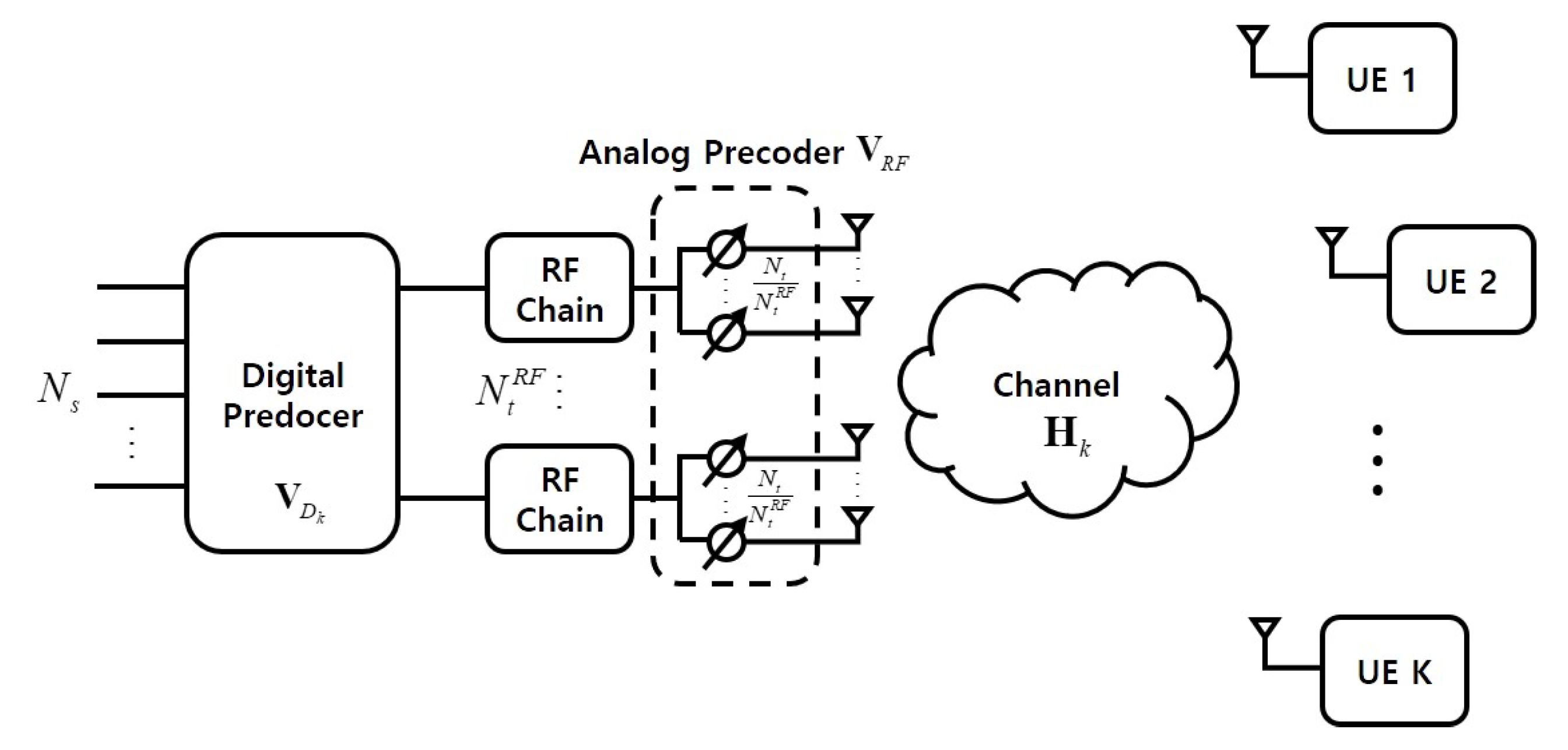
Figure 1 shows FCS hybrid beamforming system model. A transmitter is equipped with N t R F RF chains. The each of RF chains is connected to all the antenna elements with a network of phase shifters. The total number of phase shifters is N t N t R F . N s data streams transmit to the k users which have one antenna. The transmitted symbol vector is as follows,
x = V R F V D s = l = 1 k V R F V D s l ,
where V R F is N t × N t R F analog precoder matrix. V R F is implemented by using analog phase shifters, i.e., with V R F i , j = 1 and i denotes the i-th row and j denotes the j-th column. V D is N t R F × N s digital precoder matrix and s is N s × 1 data stream vector. At the transmitter, when N s = N t R F is assumed, the data stream is split into each RF chain with a digital precoder and the signal phase is adjusted with an analog precoder. The received signal by the k-th user is represented as follows,
y k = H k V R F V D k s k + H k l k V R F V D l s l + z k ,
where y k is the received symbol vector at the k-th user and H k is the N r × N t complex channel matrix between the transmitter and the k-th user. N r is the number of antenna of user. V R F is N t × N t R F analog precoder matrix and V D k is N t R F × N s digital precoder matrix at the k-th user. s k is a data stream vector at the k-th user. H k l k V R F V D l s l is an interference signal to the k-th user by another received RF chain. z k is an additive white Gaussian noise (AWGN) vector at the k-th user.

2.2. Partially Connected Structure

Figure 2 shows PCS hybrid beamforming system model. Unlike the FCS hybrid beamforming system model, a transmitter is equipped with N t R F RF chains and each of RF chains is connected to one sub-array with N t / N t R F . The total number of phase shifters is N t . Because the total number of phase shifters is N t N t R F and N t at the FCS, PCS hybrid beamforming systems respectively, the PCS hybrid beamforming system has low hardware complexity of the analog beamformer comparing the FCS hybrid beamforming system. The remaining parameters and equations are same with FCS hybrid beamforming system.

2.3. 3-Dimension Spatial Channel Model

Figure 3 shows 3-dimension spatial channel model (3D SCM) [14,15]. The SCM is a 3D geometric probability model that describes the environment scattered by clutter in the azimuth and elevation angles between the transmitter and the user. Additionally, the 3D SCM is applied to the hybrid beamforming system to increase the reliability of the communication environment in the actual 3-dimensional space. The equation of 3D SCM is as follows,
H 3 D = N t N r M m = 1 M a r ( ϕ m r , θ m r ) a t ( ϕ m t , θ m t ) H ,
where M denotes the number of multi-paths by scattering of the signal. a t ( ϕ m t , θ m t ) denotes steering vector for azimuth and elevation angles at the transmitter. Also, a r ( ϕ m r , θ m r ) denotes steering vector for azimuth and elevation angles to the user.
Figure 4 shows the structure of antenna arrays connecting the RF chain [16,17,18,19,20]. If the distance is far between the antenna arrays and the users, the same azimuth and elevation angles are radiated for all antennas. The matrix in the analog precoder is denoted as follows,
V R F = d i a g a t ( ϕ 1 , θ 1 ) , a t ( ϕ 2 , θ 2 ) , , a t ( ϕ N t R F , θ N t R F ) ,
where a t ( ϕ i , θ i ) denotes the steering vector connecting the i-th RF chain and V R F denotes the diagonal matrix with the elements of a t ( ϕ i , θ i ) . a t ( ϕ i , θ i ) is denoted as follows,
a t ( ϕ i , θ i ) = 1 N t e 2 π λ r i d ,
r i = sin θ i cos ϕ i sin θ i sin ϕ i cos θ i ,
d = s x s y + ( p 1 ) d H s z + ( q 1 ) d V ,
where r i denotes spherical unit vectors expressed in Cartesian coordinates for the i-th RF chain and d denotes location vectors of antenna elements. p denotes the number of antenna elements in the horizontal direction and q denotes the number of antenna elements in the vertical direction. d H denotes interval of the elements in the horizontal direction and d V denotes interval of the elements in the vertical direction.

3. Conventional Hybrid Beamforming System

The hybrid beamforming system based on codebook selects the most suitable analog beam pattern with the channel status of each user in the codebook storing the predesigned analog beam patterns. In addition, the hybrid beamforming system based on codebook designs a digital precoder that eliminates user interference by using ZF scheme based on selected analog beam pattern. The hybrid beamforming system based on codebook is a realistic method and it can be applied to 5G NR. Also, it is important to improve the error performance and the average sum rate. The hybrid beamforming system based on codebook has the advantage of reducing the required channel feedback overhead. The hybrid beamforming system is a method of selecting analog beam pattern within a predesigned codebook to reduce the required channel overhead when beamformers are designed in a multi-user environment.
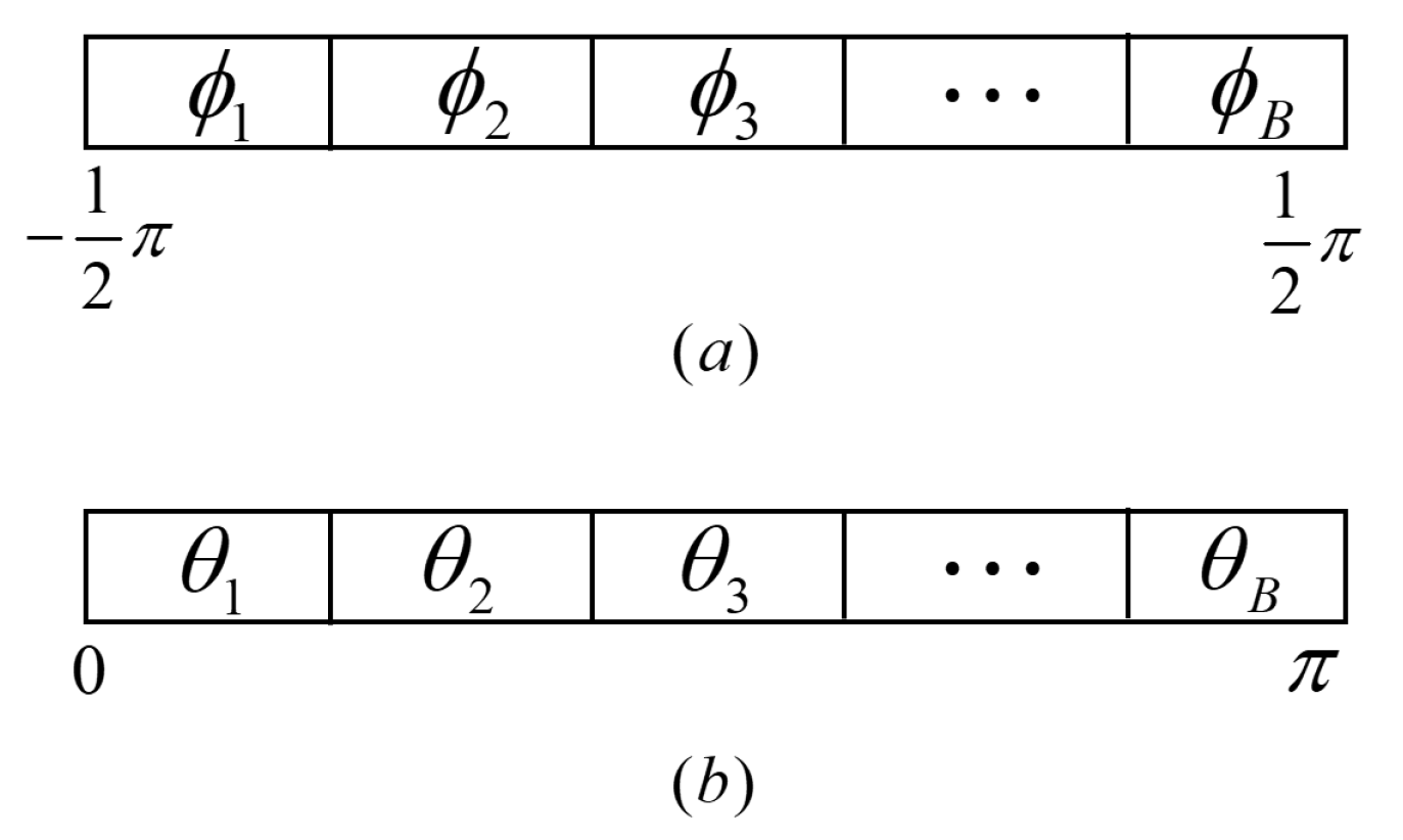
Figure 5 shows the linearly divided angles according to the B-bits at the hybrid beamforming system based on codebook. The range of azimuth angle is 1 2 π , , 1 2 π and the range of elevation angle is 0 , , π . The predesigned precoder is as follows,
V R F = V R F 1 , V R F 2 , , V R F B 2 ,
where V R F i ( i = 1 , , B 2 ) denotes the each of analog precoders. The hybrid beamforming system based on codebook divides the azimuth and elevation angles linearly according to the number of B-bits and forms beam patterns through combination of the divided azimuth and elevation angles.
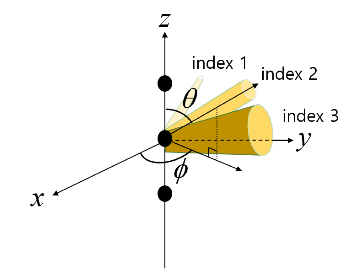
Although Figure 6 shows the 3 beam patterns to show the example of predesigned beam patterns, the hybrid beamforming system based on codebook forms B 2 beam patterns according to the number of B-bits. The conventional hybrid beamforming system divides the angle linearly without consideration of fading channels and it does not cope with the propagations which have severe frequency selectivity. Therefore, the error performance and average sum rate performance are degraded seriously in the subcarriers which go through deep fading, and it causes errors despite of the forward error correction. The next section describes the advanced hybrid beamforming system that has the same number of beam patterns but has the improved error performance and the average sum rate compared to the conventional hybrid beamforing system.

4. Advanced Hybrid Beamforming System

As mentioned in Section 2, FCS hybrid beamforming which each RF chain is connected to all antennas achieves full array gain and obtains high average sum rate. To reduce the complexity of hardware system, PCS hybrid beamforming system with the same number of antennas connected to each RF chain is proposed. Therefore, this paper proposes the beam search algorithm to increase the performance at the PCS hybrid beamforming system based on codebook. Also, it is assumed in this paper that the transmitter knows the angle of departure (AOD) of the channels and perfect channel state information (CSI) is available.
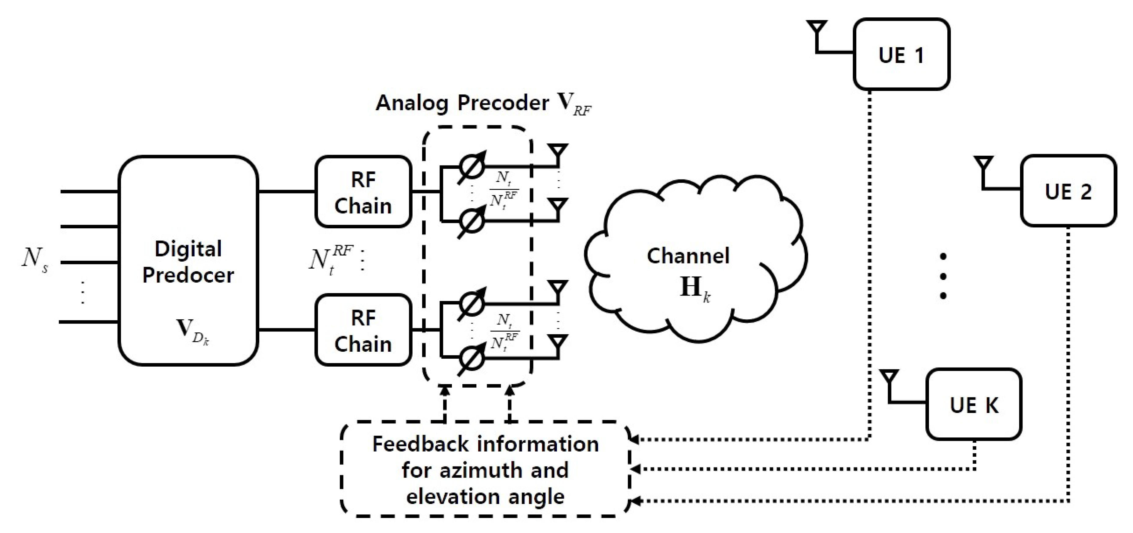
Figure 7 shows the PCS hybrid beamforming system and the feedback process of azimuth and elevation angles for the multi-paths. At the analog precoder, the azimuth and elevation angles are determined according to the number of B-bits used by the transmitter and the beam is formed according to the B-bits. The k-th user transmits the information for the received azimuth and elevation angles of multi-paths to the trasmitter. By using the azimuth and elevation angles of multi-paths proportional to the number of B-bits, B 2 beam patterns are formed. If 1-bit beamformer is used at the transmitter, the user sends the information of the azimuth and elevation angles for the multi-paths. Among them, information for the azimuth and elevation angle of the path with the highest power is used. In addition, only one beam pattern is formed. If 2-bit beamformer is used at the transmitter, information for the azimuth and elevation angle of the paths with the highest and the second power is used. In addition, four beam patterns are formed by the combination of azimuth and elevation angles.
Table 1 shows the example of the azimuth and elevation angles for the multi-paths when transmitter uses the 3-bit. Index 1 means the highest power path and index 2 means the next highest power path. Index 3 is the path with the high power after index 2. Therefore, Table 2 shows several beam patterns that can be combined by using azimuth and elevation angles corresponding to the multi-paths of Table 1.
The azimuth and elevation angles among the formed beams are estimated according to RSS as follows,
ϕ ^ k , θ ^ k = arg max H k V R F V D k 2 ,
where ϕ ^ k denotes an optimal elevation angle to be transmitted to the k-th user corresponding to the RSS. θ ^ k denotes an optimal azimuth angle to be transmitted to the k-th user corresponding to the RSS. According to the RSS, a weight matrix based on the azimuth and elevation angles is formed in the analog precoder and the data stream is transmitted to the user through the antenna array.
For PCS hybrid beamforming system, the equation of sum rate for the k-th user can be expressed as follows,
R k = log 2 1 + H k V R F V D k 2 σ 2 + l k H k V R F V D l 2 ,
where R k denotes the achievable rate of the k-th user and l k H k V R F V D l 2 denotes an interference signal power to the k-th user by another received RF chain. Because the digital precoder can use ZF scheme in PCS hybrid beamforming system, l k H k V R F V D l 2 has zero. Therefore, the sum rate of all users is as follows,
R = l = 1 k log 2 1 + H l V R F V D l 2 σ 2 .
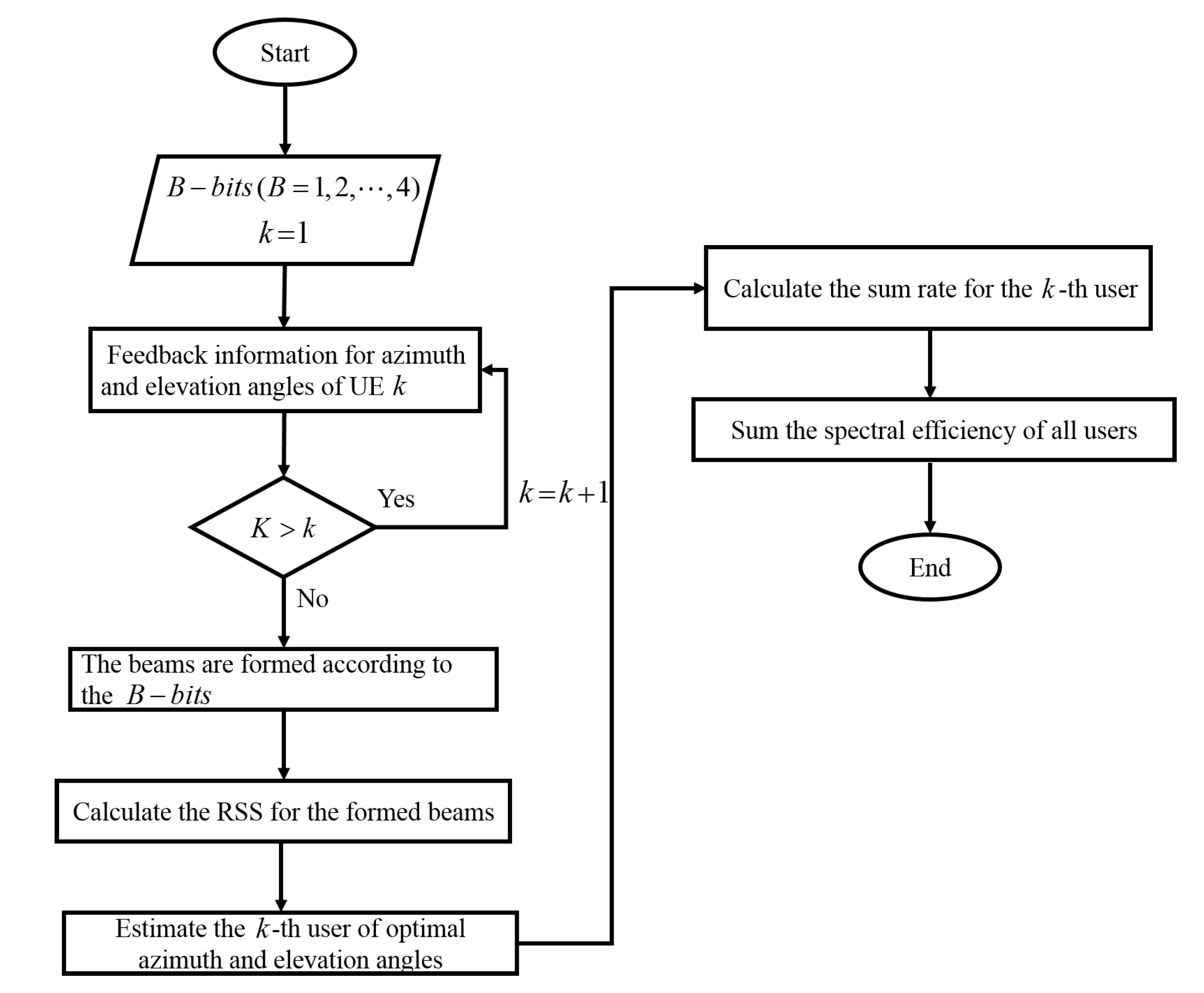
Figure 8 shows the flow chart for the advanced hybrid beamforming scheme. The flow chart contains the method for estimating the azimuth and elevation angles of the k-th user and contains the process calculating the average sum rate.
The proposed scheme is based on the nonlinear codebook design and uses the information for the azimuth and elevation angle of the multi-path with the highest power. Thus, the proposed PCS hybrid beamforming scheme has candidates which have higher reliability than the conventional PCS hybrid beamforming system, and it leads performance improvements.

5. Simulation Results

Simulation results compare the error performance and the average sum rate according to the SNR. Also, simulation results show the number of transmit antennas according to the SNR. As simulation parameters, the size of FFT is 128 and the modulation schemes are quadrature phase shift keying (QPSK) and 16 quadrature amplitude modulation (16-QAM). Also, N s , N t R F and the number of users are 4.

5.1. Bit Error Rate According to SNR

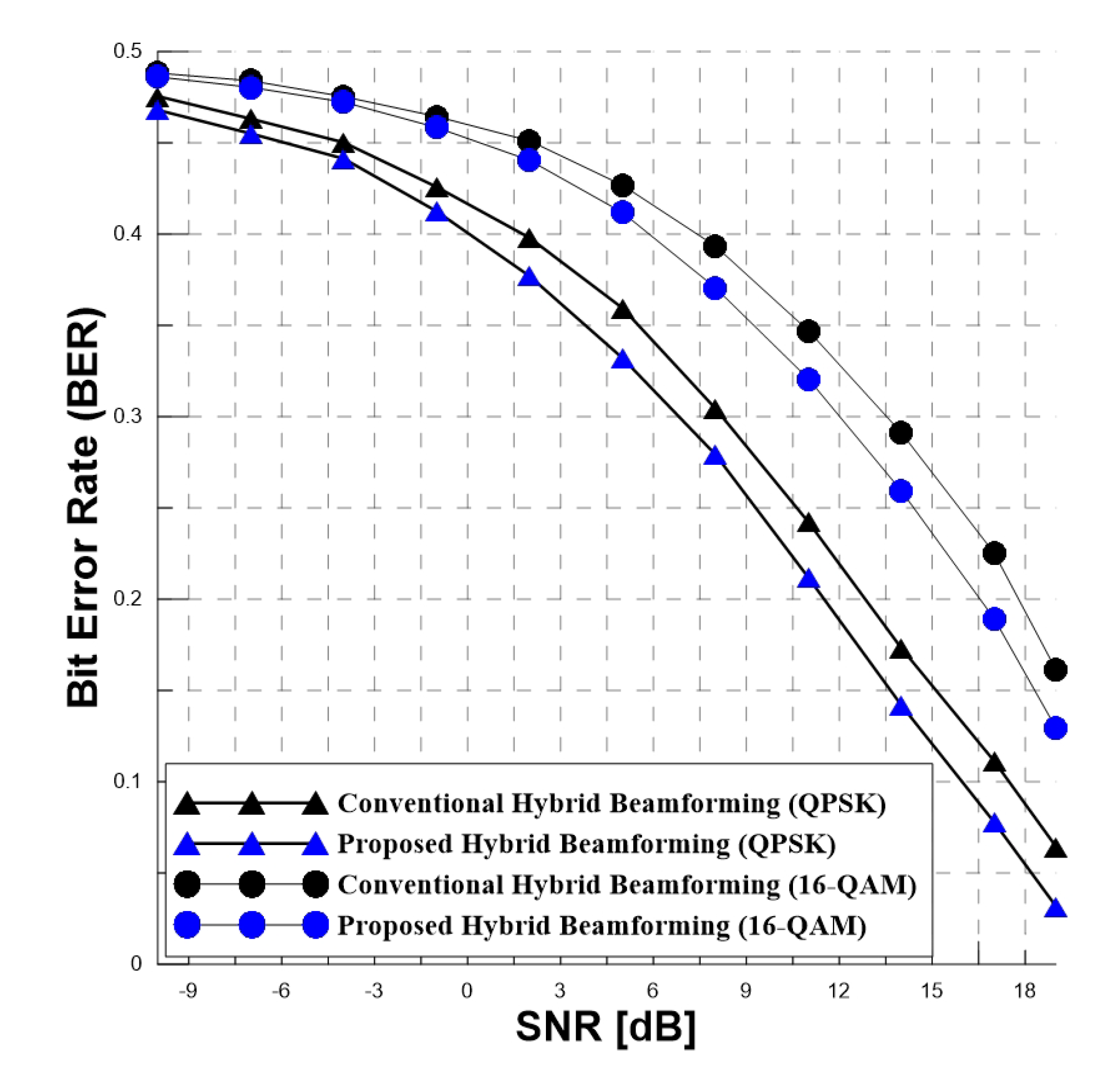
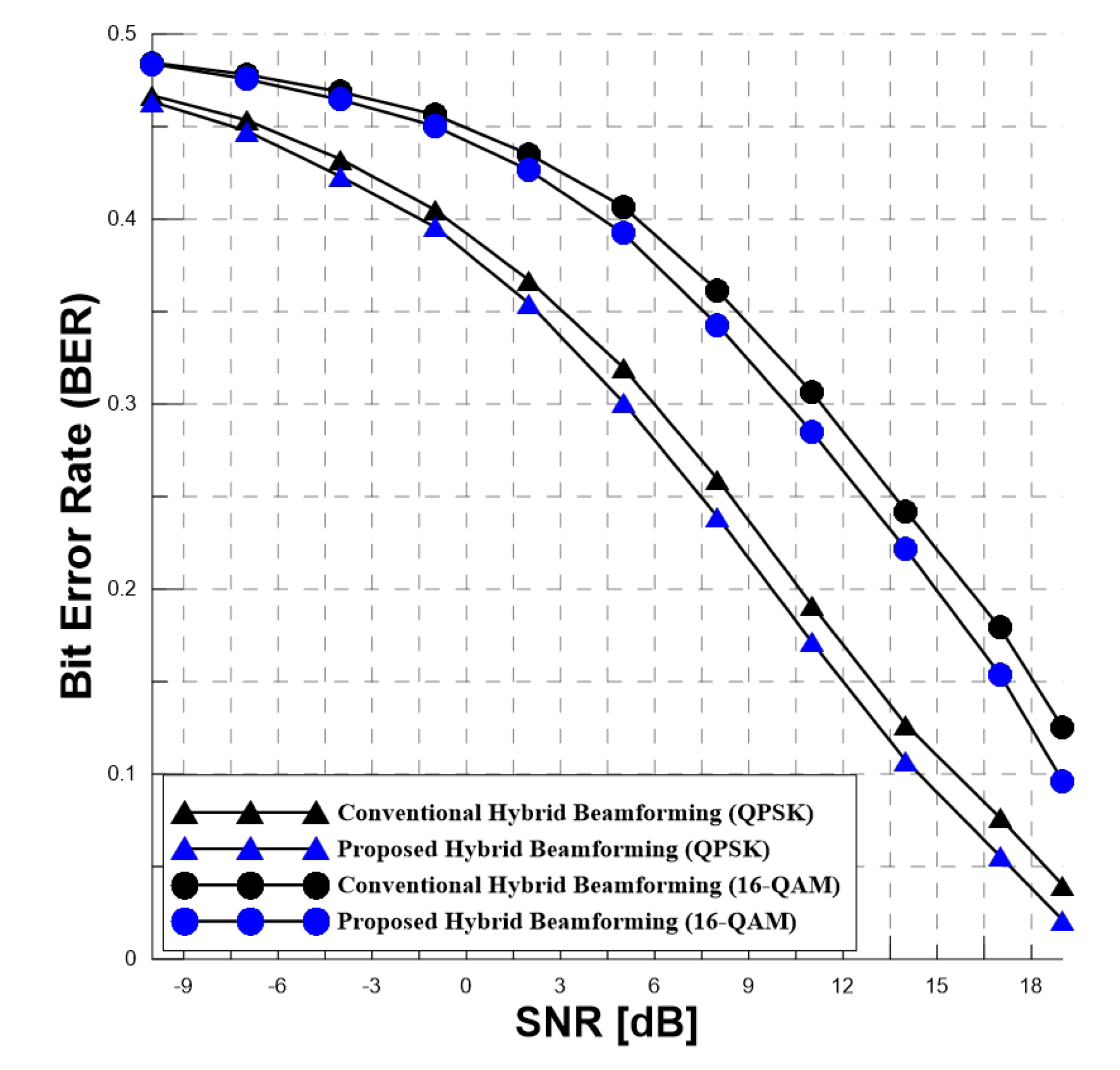
Figure 9 and Figure 10 show the bit error rate (BER) comparing the conventional hybrid beamforming system and the proposed hybrid beamforming system forming 16 beam patterns. As the results of the BER in Figure 9 and Figure 10, the proposed hybrid beamforming system has a better error performance than the conventional hybrid beamforming system. The proposed hybrid beamforming system and the conventional hybrid beamforming system have a difference about 1.5 dB with the QPSK. Also, the proposed hybrid beamforming system and the conventional hybrid beamforming system have a difference about 1.7 dB with the 16-QAM. Because the proposed hybrid beamforming system forms the beam patterns around the path with the high power, it has a better error performance than the conventional hybrid beamforming system. Also, the azimuth and elevation angles for the multi-paths with a high signal have a great influence on the error performacne.

5.2. Average Sum Rate According to SNR

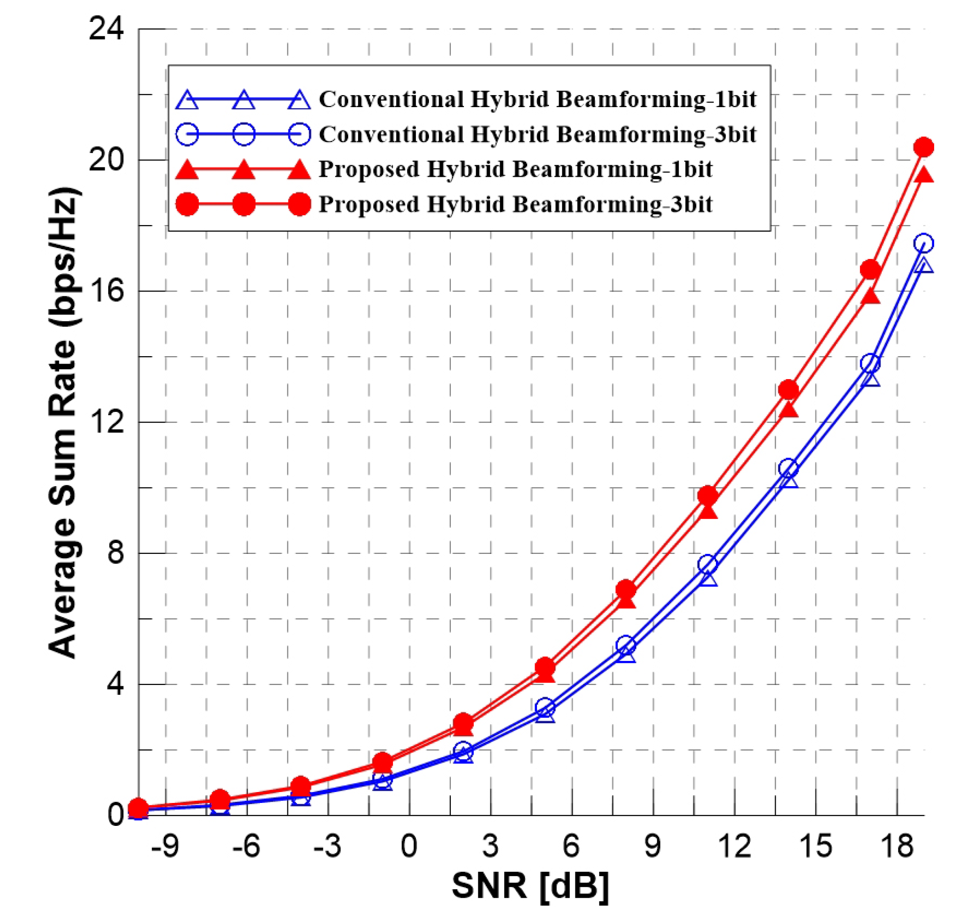
Figure 11 and Figure 12 show the average sum rate comparing the conventional hybrid beamforming system and the proposed hybrid beamforming system. Also, the figures are different according to the bit and the number of antennas. As the results of the average sum rate in Figure 11 and Figure 12, the proposed hybrid beamforming system for 1-bit has higher average sum rate than the conventional hybrid beamforming system for 1-bit. Also, the proposed hybrid beamforming system for 3-bit has higher average sum rate than the conventional hybrid beamforming system for 3-bit. Therefore, the proposed hybrid beamforming system has better average sum rate than the conventional hybrid beamforming system because the conventional hybrid beamforming system divides the azimuth and elevation angles linearly and forms beam patterns through combination of the divided azimuth and elevation angles. However, the proposed hybrid beamforming system forms the beam patterns around the path with the high power.

5.3. Average Sum Rate According to the Number of Transmit Antennas

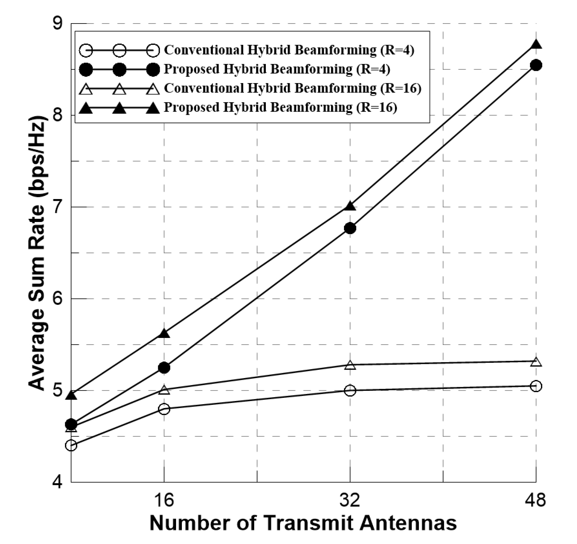
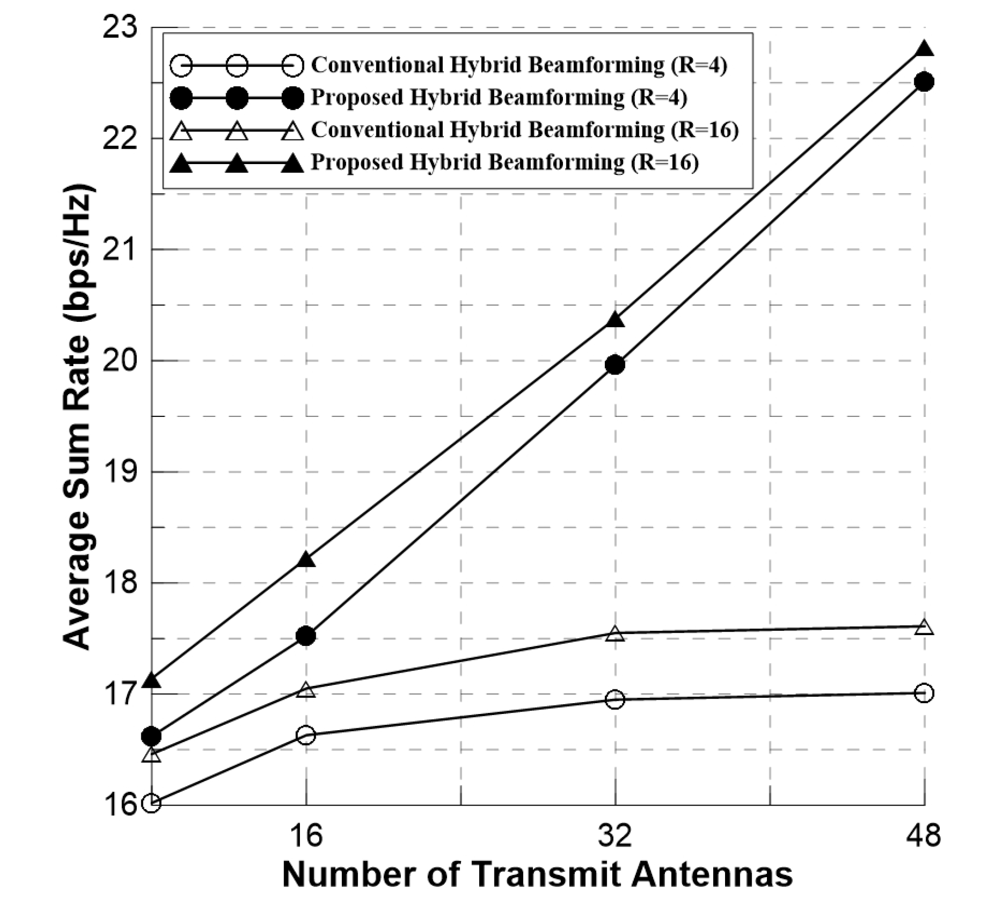
Figure 13 and Figure 14 show the average sum rate according to the number of transmit antennas comparing the conventional hybrid beamforming system and the proposed hybrid beamforming system. Also, Figure 13 and Figure 14 show the average sum rate of hybrid beamforming system forming 4 and 16 beam patterns. Additionally, Figure 13 shows the simulation results at SNR of 8 dB and Figure 14 shows the simulation results at SNR of 20 dB. As the results in Figure 13 and Figure 14, the average sum rate of the conventional hybrid beamforming system is high when the number of transmit antennas increases. However, the increase rate of average sum rate is very low according to the number of transmit antennas. On the other hand, the average sum rate of proposed hybrid beamforming system is high when the number of transmit antennas increases and the increase rate of average sum rate is high according to the number of transmit antennas. It means that the conventional hybrid beamforming system has low antenna gain when the number of transmit antennas increases. However, the proposed hybrid beamforming system has high antenna gain when the number of transmit antennas increases. In addition, the simulation results can be seen that proposed hybrid beamforming has better average sum rate than the conventional hybrid beamforming system when transmitter sends the data stream using the same number of beam patterns.

5.4. Computing Complexity According to the Number of Bits

Table 3 shows the computing complexity according to the number of bits comparing the conventional and the proposed hybrid beamforming system. The equation of computing complexity is as follows,
28 × k × B 2 × I
Because the rest of the elements are the same, other parameters such as the number of antennas and the size of FFT are not considered. I is the number of iteration. As simulation parameters, the number of users are 4 and the number of iteration is 10,000. The computational complexity for the conventional and the proposed hybrid beamforming system is same. The only difference between the conventional and the proposed hybrid beamforming systems are feedback channel. However, the feedback channel at the proposed hybrid beamforming has a little burden.

6. Conclusions

In 5G NR, wireless communication technology evolved as demand for increasing the data rate in MU-MIMO systems. In particular, the improvement of the data rate is important in mmWave communication technology using the large-scale arrays. In 5G NR, the technique improving the average sum rate was studied continuously. In this paper, the advanced hybrid beamforming system is proposed to improve the error performance and the average sum rate. The transmitter receives the information of azimuth and elevation angles for the multi-paths by the feedback process. In addition, the azimuth and elevation angles are determined according to the number of B-bits used by the transmitter and the beam patterns are formed according to the B-bits. By using the azimuth and elevation angles of multi-paths proportional to the number of B-bits, B 2 beam patterns are formed. Finally, the azimuth and elevation angles among the formed beam patterns are estimated according to Equation (9). It is shown that the proposed hybrid beamforming system has higher error performance and the average sum rate than the conventional hybrid beamforming system. Also, the proposed hybrid beamforming system has better error performance and the average sum rate than the conventional hybrid beamforming system when transmitter sends the data stream using the same number of beam patterns.
This paper is designed to improve the bit error rate and the average sum rate in codebook based hybrid beamforming applied in 5G NR. However, the technique proposed in this paper has some performance degradation factors. An accuracy of channel estimations are very low when the number of RF chains is decreased. Specifically, the proposed codebook design is based on the channel state information. Thus, the error performance and average sum rate performance are degraded seriously as the number of RF chains is decreased, and the performance limitations are noticeable. Also, in the frequency selective fading, the design of analog precoding which copes with severe selectivity perfectly is very complex. If the above problems are solved with feature work, the proposed technique will be an efficient beamsearch algorithm in 5G NR.

Author Contributions

Conceptualization, S.-J.S.; methodology, S.-J.S. and S.L.; software, S.-J.S. and J.-H.R.; validation, S.-J.S., S.L., W.-S.L., and H.-K.S.; formal analysis, J.-I.B., S.-J.S.; investigation, J.-I.B., S.L. and W.-S.L.; writing—original draft preparation, S.-J.S.; writing—review and editing, S.-J.S. and J.-H.R.; supervision, H.-K.S.; project administration, H.-K.S. All authors have read and agreed to the published version of the manuscript.

Funding

This research was supported by the MSIT(Ministry of Science and ICT), Korea, under the ITRC(Information Technology Research Center) support program(IITP-2019-2018-0-01423) supervised by the IITP(Institute for Information & communications Technology Promotion) and was supported by Basic Science Research Program through the National Research Foundation of Korea(NRF) funded by the Ministry of Education(2020R1A6A1A03038540).

Conflicts of Interest

The authors declare no conflict of interest.

References

  1. Ji, M.; Wang, Z.; Liu, Q.; Zhou, L. A hardware-efficient hybrid beamforming solution for mmWave MIMO systems. IEEE Wirel. Commun. 2019, 26, 137–143. [Google Scholar]
  2. Haro, C.A.; Mestre, X. Learning and data-driven beam selection for mmWave communications: An angle of arrival-based approach. IEEE Access 2019, 7, 20404–20415. [Google Scholar] [CrossRef]
  3. Zhang, J.; Zheng, Z.; Zhang, Y.; Xi, J.; Gui, G. 3D MIMO for 5G NR: Several observations from 32 to massive 256 antennas based on channel measurement. IEEE Commun. Mag. 2018, 56, 62–70. [Google Scholar] [CrossRef]
  4. Huang, Y.; Li, Y.; Ren, H.; Lu, J.; Zhang, W. Multi-panel MIMO in 5G. IEEE Commun. Mag. 2018, 56, 56–61. [Google Scholar] [CrossRef]
  5. Ro, J.H.; Lee, W.S.; Ha, J.K.; Song, H.K. An Efficient precoding method for improved downlink massive MIMO system. IEEE Access 2019, 7, 112318–112326. [Google Scholar] [CrossRef]
  6. Choi, S.J.; Shim, S.J.; You, Y.H.; Cha, J.S.; Song, H.K. Novel MIMO detection with improved complexity for near-ML detection in MIMO-OFDM systems. IEEE Access 2019, 7, 60389–60398. [Google Scholar] [CrossRef]
  7. Sohrabi, F.; Yu, W. Hybrid analog and digital beamforming for mmWave OFDM lcarge-scale antenna arrays. IEEE J. Sel. Area Commun. 2017, 35, 1432–1443. [Google Scholar] [CrossRef] [Green Version]
  8. Sohrabi, F.; Yu, W. Hybrid digital and analog beamforming design for large-scale antenna arrays. IEEE J. Sel. Top. Signal Process. 2016, 10, 501–513. [Google Scholar] [CrossRef] [Green Version]
  9. Jiang, L.; Jafarkhani, H. Multi-user analog beamforming in millimeter wave MIMO systems based on path angle information. IEEE Trans. Wirel. Commun. 2019, 18, 608–619. [Google Scholar] [CrossRef]
  10. Kwon, K.H.; Hwang, D.D.; Song, H.K.; Nam, S.S. Full-duplex with self-energy recycling in the RF powered multi-antenna relay channels. IEEE Signal Process. Lett. 2019, 26, 1516–1520. [Google Scholar] [CrossRef]
  11. Chen, Y.; Chen, D.; Jiang, T. Non-uniform quantization codebook-based hybrid precoding to reduce feedback overhead in millimeter wave MIMO systems. IEEE Trans. Commun. 2019, 67, 2779–2791. [Google Scholar] [CrossRef] [Green Version]
  12. He, S.; Wang, J.; Huang, Y.; Ottersten, B.; Hong, W. Codebook-based hybrid precoding for millimeter wave multiuser systems. IEEE Trans. Signal Process. 2017, 65, 5289–5304. [Google Scholar] [CrossRef]
  13. Bjornson, E.; Van der Perre, L.; Buzzi, S.; Larsson, E.G. Massive MIMO in sub-6 GHz and mmWave: Physical, practical, and use-case differences. IEEE Wirel. Commun. 2019, 26, 100–108. [Google Scholar] [CrossRef] [Green Version]
  14. Ademaj, F.; Taranetz, M.; Rupp, M. 3GPP 3D MIMO channel model: A holistic implementation guideline for open source simulation tools. Eurasip J. Wirel. Commun. Netw. 2016, 55, 1–14. [Google Scholar] [CrossRef] [Green Version]
  15. Kim, W.C.; Paek, M.J.; Song, H.K. Relay selection scheme for multi-hop transmission of MU-MIMO system. Appl. Sci. 2018, 8, 1747. [Google Scholar] [CrossRef] [Green Version]
  16. Reil, M.; Lloyd, G. Millimeter-Wave Beamforming: Antenna Array Design Choices and Characterization; Rohde and Schwarz: Munich, Germany, 2016; pp. 1–26. [Google Scholar]
  17. Hu, Y.; Hong, W. A novel hybrid analog-digital multibeam antenna array for massive MIMO applications. In Proceedings of the 2018 IEEE Asia-Pacific Conference on Antennas and Propagation, Auckland, New Zealand, 5–8 August 2018. [Google Scholar]
  18. Zhang, J.A.; Huang, X.; Dyadyuk, V.; Guo, Y.J. Massive hybrid antenna array for millimeter-wave cellular communications. IEEE Wirel. Commun. 2015, 22, 79–87. [Google Scholar] [CrossRef]
  19. Kim, C.H.; Son, J.S.; Kim, T.Y.; Seol, J.Y. On the hybrid beamforming with shared array antenna for mmWave MIMO-OFDM systems. In Proceedings of the 2014 IEEE Wireless Communications and Networking Conference, Istanbul, Turkey, 6–9 April 2014. [Google Scholar]
  20. Li, Y.; Zhang, Y.; Han, Z.; Tang, S.; Jing, L.; Chiu, C.Y.; Murch, R. Analog precoding using highly reconfigurable antennas. IEEE Wirel. Commun. Lett. 2020, 9, 648–652. [Google Scholar] [CrossRef]
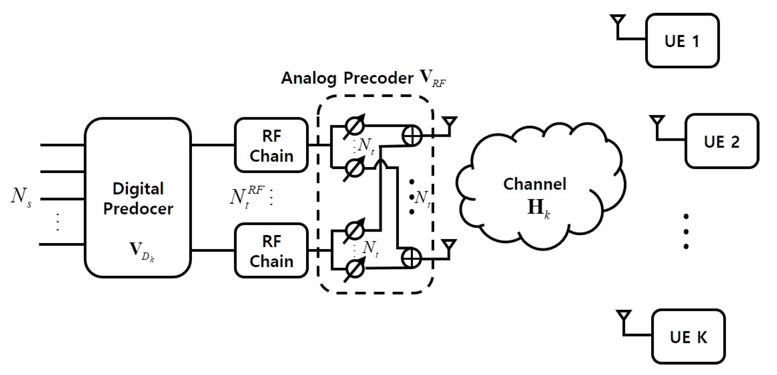
Figure 1. The architecture of fully connected structure hybrid beamforming system.
Applsci 10 05961 g001
Figure 2. The architecture of partially connected structure hybrid beamforming system.
Applsci 10 05961 g002
Figure 3. 3-dimension spatial channel model.
Applsci 10 05961 g003
Figure 4. The structure of antenna arrays.
Applsci 10 05961 g004
Figure 5. The linearly divided angles according to the B-bits. (a) azimuth angles; (b) elevation angles.
Applsci 10 05961 g005
Figure 6. The example of predesigned beam patterns at the antenna arrays.
Applsci 10 05961 g006
Figure 7. The PCS hybrid beamforming system including the feedback process.
Applsci 10 05961 g007
Figure 8. The flow chart for the proposed hybrid beamforming scheme.
Applsci 10 05961 g008
Figure 9. The bit error rate of the hybrid beamforming schemes, N t = 16.
Applsci 10 05961 g009
Figure 10. The bit error rate of the hybrid beamforming schemes, N t = 32.
Applsci 10 05961 g010
Figure 11. The average sum rate of the hybrid beamforming schemes, N t = 16.
Applsci 10 05961 g011
Figure 12. The average sum rate of the hybrid beamforming schemes, N t = 32.
Applsci 10 05961 g012
Figure 13. The average sum rate of the hybrid beamforming schemes according to the number of transmit antennas, SNR = 8 dB.
Applsci 10 05961 g013
Figure 14. The average sum rate of the hybrid beamforming schemes according to the number of transmit antennas, SNR = 20 dB.
Applsci 10 05961 g014
Table 1. Example of the azimuth and elevation angles for the multi-paths.
Multi-Path IndexElevation Angle ( θ ) Azimuth Angle ( ϕ )
1 1 6 π 1 3 π
2 2 2 π 1 3 π
3 2 3 π 2 2 π
Range of angle 0 , π 1 2 π , 1 2 π
Table 2. Example of the beam patterns.
Beam Pattern Index θ , ϕ
1 1 6 π , 1 3 π
2 1 6 π , 1 3 π
3 1 6 π , 2 2 π
4 2 2 π , 1 3 π
9 2 3 π , 2 2 π
Table 3. The computing complexity according to the number of bits.
1 bit2 bit3 bit
Conventional Hybrid Beamforming1,120,0004,480,00010,080,000
Proposed Hybrid Beamforming (Feedback channel is required)1,120,0004,480,00010,080,000