Article

Safe Proximity Operation to Rotating Non-Cooperative Spacecraft with Complex Shape Using Gaussian Mixture Model-Based Fixed-Time Control

College of Aerospace Science and Engineering, National University of Defense Technology, Changsha 410073, China
*
Author to whom correspondence should be addressed.
Appl. Sci. 2020, 10(17), 5986; https://doi.org/10.3390/app10175986
Submission received: 28 July 2020 / Revised: 20 August 2020 / Accepted: 26 August 2020 / Published: 29 August 2020
(This article belongs to the Section Aerospace Science and Engineering)

Abstract

:
This paper studies the safety control problem for rotating spacecraft proximity maneuver in presence of complex shaped obstacles. First, considering the attitude change of the target spacecraft, a dynamic model of close-range relative motion in a body-fixed coordinate system is derived using a novel approach. Then, the Gaussian mixture model (GMM) is utilized to reconstruct the complex shape of the spacecraft, and a novel GMM-based artificial potential function (APF) is proposed to represent the collision avoidance requirement. By combining GMM-based APF with fixed-time stability methodology, a fixed-time control (FTC) is designed for close-range proximity operation to a rotating spacecraft having a complex shape. The presented GMM-FTC scheme can guarantee the convergence of relative state errors, and ensure that no collision occurs. Finally, simulation results are provided to illustrate the feasibility of the proposed control approach.

1. Introduction

Nowadays, because of factors like solar panels that fail to unfold, communication failure, exhaustion of thruster fuel, collision, etc., many spacecraft have decayed and become non-cooperative target like space debris. In order to improve the utilization value of space and save on costs to the aerospace industry, research and development for on-orbit service are ever-increasing. For example, the Cubesat Proximity Operations Demonstration (CPOD) implemented an on-orbit demonstration of rendezvous, proximity operations and docking of two 3U Cubesats [1]; MEV-1 completed the proximity operation to IS-901 satellite, and inserted the docking mechanism into the throat of IS-901 engine nozzle to realize rendezvous and docking; the RemoveDebris mission has successfully demonstrated on-orbit net and harpoon capture and the whole sequence of operations like vision-based navigation for the purpose of Active Debris Removal (ADR) [2]; also the e.Deorbit project has planned to testing technology to clear out space debris [3].
Proximity maneuvers are the premise of providing on-orbit services such as maintenance, filling, and taking over. Convergence and high efficiency of APF has been theoretically proven, and the APF can be applied to path planning of autonomous proximity maneuvers. With the APF, the motion space of spacecraft can be modeled using a potential field, where a high potential field represents the dead zone and the lower the potential field, the freer the movement [4]. Thus, spacecraft can implement proximity and docking maneuvers along the negative gradient of the APF. McCamish et al. [5] proposed a guidance algorithm, which combined linear quadratic regulator (LQR) with APF method, and the effectiveness has been verified on the Space-borne Autonomous Formation Flying Experiment (SAFFE). In order to overcome the adverse effects of disturbances and uncertainties in the space environment, a method that combines APF with sliding mode control (SMC) was proposed to ensure collision avoidance in proximity and docking maneuvers with strong robustness and fast convergence [6,7,8,9]. Moreover, adaptive control methods are also widely employed with APF and SMC for better response to disturbances and uncertainties in space [10].
However, failed spacecraft in space are often unable to maintain a stable attitude or rotation. For a rotating target, Costantinos et al. [11] analyzed the reachability of planar docking with a rotating target, and the reachability was found to depend on a set of initial conditions, which is related to the rotating angular velocity and control force amplitude. Ventura et al. [12] proposed an onboard trajectory planning generated by a direct optimization method, which is based on the inversion of the system dynamics for autonomous docking between a controlled spacecraft and an uncontrolled tumbling target in circular orbit. Moreover, the problem of minimum-time and minimum-energy optimal trajectories of proximity of a powered chaser and a non-cooperative target attracted a lot of attention [13,14,15]. In this paper, the target’s attitude change is considered into the dynamic model and is expressed in the body coordinate system. Then a controller is designed to achieve safe proximity operation to the rotating target. The method can integrate the target’s attitude change into the orbital dynamics and will simplify the controller design.
In practice, spacecraft are often composed of large solar panels, for the purpose of generating as much solar energy as possible, and antennas with different lengths, for communication. The complex shape will increase the risk of collision in proximity and docking maneuvers, especially when the target fails and cannot cooperate to complete maneuvers. To address this issue, some scholars use the geometric envelope method to describe the basic shape of the spacecraft, such as ellipsoid envelope [16] and super quadratic envelope [17], which ignored the details of the spacecraft shape. Besides, some modified APF methods were proposed to give more precise constraints of trajectory of proximity, such as sigmoid function-based APF [18], Cissoid-based APF [19,20], and harmonic functions based APF [21]. This paper proposed Gaussian Mixture model (GMM)-based APF, which combines the characteristics of the two methods. GMM has been widely used in estimation of space object collision probability [22], uncertainty propagation [23,24], trajectory optimization [25], model construction [26], and image reconstruction [27]. Based on GMM, an equal-collision-probability-curve method is proposed for safe spacecraft close-range proximity maneuvers, which uses the collision-probability to describe the space around the target spacecraft for safety problem [28,29]. In this paper, the GMM is used to reconstruct the complex shape of spacecraft, and a novel APF is built to constrain the motion trajectory. Compared with existing modified APF, the GMM-based APF can depict obstacle constraints of arbitrary targets with complex shape.
Despite the fact that proximity operation task is performed with the aforementioned control schemes, the convergence or finite-time convergence can only be guaranteed asymptotically. Time for stabilization is seriously affected by the initial conditions of the system [30]. Nevertheless, time constraints are often needed to be considered in on-orbit service. Therefore, a prior precise estimation of the settling-time is necessary. The notion of fixed-time stability (FTC) has been proposed to provide a desired finite time convergence regardless of initial condition, which features that the bound of settling-time is just related to the control gains [31]. The characteristics of fixed-time stability have attracted many studies and are widely used in different control scenarios. For example, Zuo et al. [32] summarized the latest progress in applying fixed-time cooperative control to multi-agent systems. Liu et al. [33] discussed the local and global fixed-time stability respectively for a port-Hamiltonian system based on interconnected and damped distributed passive control technology, and defined the fixed-time stable area and stable boundary. In terms of spacecraft on-orbit control applications, Jiang, Shi, Chen et al. [34,35,36] designed an adaptive nonsingular fixed-time sliding mode controller with the consideration of system uncertainty, external interference, actuator failure, and input saturation. Fixed-time convergence of the controller can be guaranteed. Ton et al. [37] designed a sliding mode controller for spacecraft system with flexible attachments, which can restrain disturbance and make the attitude-tracking error converge to origin in a fixed time. Yanchao et al. [38] designed a closed-loop control law based on non-linear feedback FTC for spacecraft fixed-point hovering, and the principle of fixed-time stabilization had been described and proved. Considering the control problem of presupposed time transfer operation with tumbling target, Hu et al. [39] designed a time-varying sliding mode surface, and a control scheme with sliding manifold was proposed to achieve fixed-time convergence of relative parameter tracking error. K.T. et al. [40] designed a non-singular terminal sliding mode controller with fixed-time convergence for approaching non-cooperative spacecraft with disturbance and parameter uncertainty, which can achieve timing tracking control, as well as avoid singularity and chattering.
The study of this paper focuses on control design for safe proximity to a rotating spacecraft with complex shape so that superior features including collision avoidance and fixed-time convergence property. Motivated by the discussion above, the principal contributions of this paper can be outlined as follows:
(1)
A novel GMM-based potential function is proposed, which can depict obstacle constraints of arbitrary targets with complex shape and provide attraction force to the desired position and repulsive force to avoid collision to the components of target spacecraft.
(2)
A compound controller is designed for ultra-close-range safe proximity based on GMM and FTC method, which can guarantee not only collision avoidance, but also fixed-time convergence to the desired state.
The rest of this paper is organized as follows: in the next section, the novel dynamic model in body-fixed frame is derived and the required definition is given. The main methodologies are presented in Section 3, in which the GMM-based APF is stated, and a GMM-based FTC is developed to achieve collision avoidance and fixed-time convergence. Finally, simulation results and conclusions are given in Section 4 and Section 5, respectively.

2. Problem Statement

2.1. Mathematical Preliminaries

The Euclidean norm of a vector or the induced norm of a matrix is represented by ‖ ‖. The n × n identity matrix is denoted by I n . For the given vector x = [ x 1 , x 2 , x 2 ] T 3 and a constant ζ , we define x ζ = [ x 1 ζ , x 1 ζ , x 1 ζ ] T , sig ζ ( x ) = [ | x 1 | ζ sgn ( x 1 ) , | x 2 | ζ sgn ( x 2 ) , | x 3 | ζ sgn ( x 3 ) ] T in which sgn(·) represents the sign function, and the skew symmetric matrix S ( x ) 3 × 3 is defined as
S ( x ) = x × = [ 0 x 3 x 2 x 3 0 x 1 x 2 x 1 0 ] .
Lemma 1 
([31]). If there exists a continuous radially unbound function V: n + { 0 } , any solution x(t) of V satisfies the inequality V ˙ ( x ) ( α V p ( x ) + β V q ( x ) ) k , where α ,   β ,   p ,   q ,   k > 0 and p k < 1 ,   q k > 1 , then, for the nonlinear system x ˙ = f ( x , t ) , the equilibrium point is fixed-time stable and the stability time satisfies the inequality constraint T ( x 0 ) 1 / α k ( 1 p k ) + ( 1 / β k ( q k 1 ) ) , x 0 n .
Corollary 1.
Let k = 1 in Lemma 1, assume that there is a Lyapunov function V(x(t)): n + { 0 } , and V ˙ ( x ) α V p ( x ) + β V q ( x ) , where α ,   β > 0 , p < 1 , and q > 1 . Then, for the nonlinear system x ˙ = f ( x , t ) , the equilibrium point is fixed-time stable and the settling time T ( x 0 ) 1 / α ( 1 p ) + ( 1 / β ( q 1 ) ) , x 0 n .
Lemma 2.
For x = [ x 1 , x 2 , x 3 ] T 3 and ζ > 0 , the following inequality holds:
x T sig ζ ( x ) = [ x 1 | x 1 | ζ sgn ( x 1 ) , x 2 | x 2 | ζ sgn ( x 2 ) , x 3 | x 3 | ζ sgn ( x 3 ) ] T x ζ + 1 .

2.2. Coordinate Frames

The proximity operation mission scenario is described in Figure 1. There are two spacecrafts, the servicer and target. The target is non-cooperative, which has a pair of solar panels and antennas, rotating and running on an elliptical orbit. To describe the relative motion of spacecraft proximity operation process, the frame system should be established first. As shown in Figure 1, there are three types of coordinate frames, including Earth-centered inertial (ECI) frame, local vertical local horizontal (LVLH) frame, and body-fixed frame. They are denoted as i = { O i ,   i i ,   j i ,   k i } , l = { O l ,   i l ,   j l , k l } , and b = { O b ,   i b ,   j b ,   k b } , respectively. i , l , and b are all right-handed system. O i is located in the center of the Earth; i i is along the direction of the vernal equinox; k i points toward the north pole; j i is perpendicular to i i and k i . O l and O b are located at the target; i l points along the instantaneous vector from Earth center to the target, j l is perpendicular to i l , pointing along the instantaneous tangential velocity; k l completes the triad. i b , j b and k b point to the three body axes of the target, respectively.

2.3. Translational Relative Dynamics

In LVLH frame, the relative position vector between the servicer and target is denoted as r = [ x ,   y ,   z ] T , then the relative dynamics can be described as [41]
r ¨ = A r + B r ˙ + f c + f d
where,
A = [ ω e 2 + 2 μ r c 3 ω ˙ e 0 ω ˙ e ω e 2 μ r c 3 0 0 0 μ r c 3 ] ,   B = [ 0 2 ω e 0 2 ω e 0 0 0 0 0 ] .
μ   =   3.986 × 10 14   m 2 / s 2 is gravitational constant of the Earth. r t is orbit radius of target spacecraft. f c is the controlled acceleration applied to the service spacecraft. f d is the external disturbance. ω e and ω ˙ e represent the angular velocity and angular acceleration of target spacecraft, which can be obtained by
ω e = ( 1 + e cos f ) 2 ( 1 e 2 ) 3 2 μ a 3   , ω ˙ e = 2 μ ( 1 + e cos f ) 3 e sin f a 3 ( 1 e 2 ) 3 2 ,
where, e is the eccentricity of the target, a is the semi-major axis, and f is the true anomaly. Equation (1) is established by Tschauner and Hempel (TH) [41], which offers better accuracy than the equation established by Clohessy and Wiltshire (CW) [42] in slightly eccentric orbits.
The above analysis establishes the dynamic model of the two spacecraft in the frame l , without considering the attitude change of the target spacecraft. When the target spacecraft rotates on the orbit, its attitude change will cause a collision risk in the proximity operation process. To remedy this problem, the dynamic model in body-fixed frame b needs to be considered, so as to depict the translational motion of servicer in rotating frame. Assuming the angle velocity of the target relative to the frame l is ω b , the vector conversion formulas between the two coordinate systems, l and b , are introduced as
r l = M b l r b ,
d r l d t = δ r b δ t + ω b × r b ,
d 2 r l d t 2 = δ 2 r b δ t 2 + δ ω b δ t × r b + 2 ω b × δ r b δ t + ω b × ( ω b × r b ) .
Then, substituting Equations (4)–(6) into Equation (1) yields
r ¨ = ( ω b × 2 + A M b l + B ω b × ω ˙ b × ) r + ( B 2 ω b × ) r ˙ + f c b + f d b .
Equation (7) can be written in the form of state equation as
X ˙ = Q X + R ( u + γ ) ,
where, X = [ r T , r ˙ T ] T , Q = [ 0 3 I 3 ω b × 2 + A M b l + B ω b × ω ˙ b × B 2 ω b × ] , R = [ 0 3 I 3 ] , u = [ 0 3 f c b ] , and the γ = [ 0 3 f d b ] .
Equation (8) is the relative dynamic model in target body-fixed frame b . Note that all the subsequent parameters are expressed in the frame b .
In the proximity operation mission, the desired state is denoted as X d = [ r d T , r ˙ d T ] T . Define e = X X d as the relative error matrix, then the relative error dynamic model can be written as
e ˙ = Q e + R ( u + u e q + γ ) ,
where, u e q = ( ω b × 2 + A M b l + B ω b × ω ˙ b × ) r d + ( B 2 ω b × ) r ˙ d r ¨ d .
When the system reaches steady state, the relative error matrix converges to zero, i.e., e = 0 ,   e ˙ = 0 . Then, if the external disturbance γ is ignored, u = u e q can be obtained from Equation (9).

3. Main Methodologies

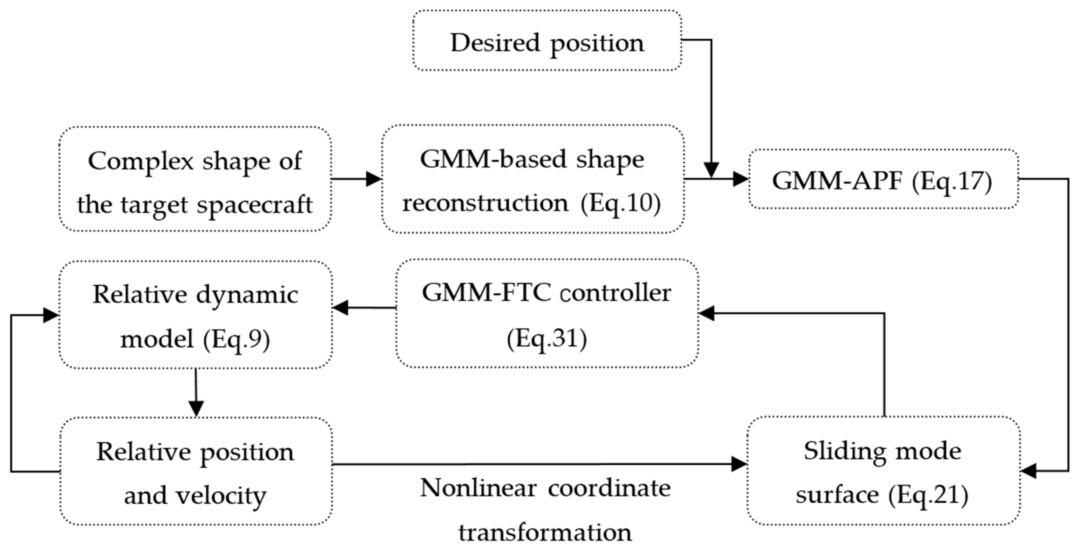
The main methodologies are summarized in Figure 2. The details of GMM-APF and GMM-FTC design are expanded in Section 3.1 and Section 3.2, respectively.

3.1. GMM-Based APF Design

When performing the proximity operation to the target, the complex shape of the target, as shown in Figure 1, must be considered for the requirement of collision avoidance. Therefore, GMM is applied, which can give an analytical expression and more accurate depiction of the target outline. The GMM can be regarded as a model composed of K single Gaussian probability density functions [28], as shown in Equation (10). These K sub-models are hidden variables of the mixed model. The GMM is used here because the Gaussian distribution has good mathematical properties and good computing performance.
p ( r | Θ ) = j = 1 K π j Φ ( r | μ j , Σ j ) = j = 1 K π j ( 2 π ) D 2 | Σ j | 1 2 e 1 2 ( r μ j ) T Σ j 1 ( r μ j ) ,
where, Φ ( r | μ j , Σ j ) means the GMM’s jth gaussian component. μ j R 3 , Σ j R 3 × 3 , and π j R are the expectation, covariance matrix, and weight of jth gaussian component, respectively. Meanwhile, π j satisfies the constrain j = 1 K π j = 1 . D is the dimension of position vector r. Θ = { θ j = ( π j , μ j , Σ j ) } contains three key parameters, which determine the GMM.
To describe the outline by GMM, the three key parameters should be solved first. Utilizing servicer’s camera or other sensing equipment, a series of feature points of the target’s surface can be obtained in space, such as point-cloud model [26], which is recorded as R = { r i = [ x i , y i , z i ] T , i = 1 , 2 , , N } . Then, using the EM algorithm, the outline, described by the feature points, can be fitted by GMM. The steps of solving GMM by EM algorithm are shown below [43].
(1)
Set the initial parameters Θ .
(2)
E-step: Calculate the probability γ i j that each data r i comes from sub-model j, based on above parameters.
γ i j = π j p ( r i | θ j ) p ( r i | Θ ) .
(3)
M-step: Calculate the next generation parameters as follows,
μ j = i = 1 N γ i j r i i = 1 N γ i j , j = 1 , 2 , , K ,
Σ j = i = 1 N γ i j ( r i μ j ) ( r i μ j ) T i = 1 N γ i j , j = 1 , 2 , , K ,
π j = i = 1 N γ i j N , j = 1 , 2 , , K .
(4)
Iterate the E-step and M-step until satisfying the condition in Equation (15). ε is small positive constant, and the superscript k means the kth calculation.
Θ ( k + 1 ) Θ ( k ) < ε
In actual calculation process, the initial parameters greatly affect the calculation results, and the E-step often takes a long time. To improve the computational efficiency, in other words, to optimize initial parameters μ j , the K-means clustering algorithm is employed. The main effect of K-means is to divide a set of data into K clusters according to Euclidean distance, the steps of which are as follows [44].
(1)
Set the initial K means.
(2)
Calculate the Euclidean distance between r i and each mean μ j (j = 1, 2, …, K), then, dividing r i to the nearest cluster center, i.e., mean and recording as r i j .
(3)
Recalculate each cluster center by the data in same cluster.
(4)
Iterate the steps (2) and (3) until Δ J = | J ( k + 1 ) J ( k ) | < ε , J is the distortion function of K-means, written as
J = 1 N j = 1 K i = 1 , r i μ j N r i j μ j 2
The basic principle of the APF method is to construct an analytical scalar function related to states, usually composed of two types of fields: attractive potential field and repulsive potential field. Traditionally, the attractive potential field is a bowl-shaped function, while the repulsive potential field is a hill-shaped function around the restricted area. Therefore, when the object moves along the negative gradient of the potential field, it can reach the desired position without violating the path constraints.
In this paper, a novel artificial potential function based on GMM is proposed. The whole potential function is expressed as
ϕ ( r , r f ) = ϕ a t t ( r , r f ) + ϕ r e p ( r , r f ) ,
where, ϕ a t t and ϕ r e p are the attractive potential function and repulsive potential function, respectively.
For the repulsive potential function ϕ r e p , it should be designed to satisfy the following properties: (1) ϕ r e p equals zero when the service spacecraft reaches the desired position; (2) ϕ r e p tends to infinity when the service is close to the target structural components. Therefore, based on the GMM, the repulsive ϕ r e p is designed as
ϕ r e p = 1 2 ( r r f ) T M ( r r f ) j = 1 K π j ( 2 π ) D 2 | Σ j | e 1 2 ( r μ j ) T Σ j 1 ( r μ j ) ,
where, M is a positive definite symmetric matrix. The GMM-based repulsive potential function, as shown in Equation (18), can provide a potential field for collision avoidance constrained by the complete shape of the target spacecraft without ignoring any details. It is worth noting that the GMM-based repulsive potential function is suitable for arbitrarily complex shape.
The attractive function ϕ a t t is designed in the classic form [19]
ϕ a t t = 1 2 ( r r f ) T P ( r r f ) ,
where, P is a positive definite symmetric matrix.
With the novel GMM-based potential function, as shown above, service spacecraft is able to avoid collision with the target’s complex shape structural components, such as solar panel and antenna, as well as to implement proximity operation.

3.2. GMM-Based Fixed-Time Controller Design

In this section, a novel nonlinear feedback controller is proposed for safe proximity operation to spacecraft with complex shape, by combining the GMM with fixed-time control method.
By defining y 1 = e 3 and y 2 = e ˙ 3 , and ignoring the external disturbance f d , Equation (8) can be reduced to the block form
y ˙ 1 = A 11 y 1 + A 12 y 2 y ˙ 2 = A 21 y 1 + A 22 y 2 + A 23 ( u + u e q ) ,
where, A 11 = 0 3 , A 12 = A 23 = I 3 , A 21 = ω b × 2 + A M b l + B ω b × ω ˙ b × and A 22 = B 2 ω b × .
Introduce the nonlinear coordinate transformation s = Φ ( y ) [31]:
s 1 = y 1 + φ 1 s 2 = y 2 + α 1 ( y 1 + φ 1 ) + β 1 ( y 1 + φ 1 ) 3 + φ 1 y 1 y 2 ,
where, α 1 , β 1 , k s 3 × 3 , φ 1 = k s r ϕ is related to the GMM-based artificial function in Equation (17). Then, through the transformation, Equation (20) can be transformed into
s ˙ 1 = α 1 s 1 β 1 s 1 3 + s 2 s ˙ 2 = Λ ( y 1 ) y 2 + k s Γ ( y 1 , y 2 ) + [ k s ϒ ( y 1 ) + I 3 ] y ˙ 2 ,
where,
Λ ( y 1 ) = [ α 1 + 3 β 1 ( y 1 + k s r ϕ ) 2 ] ( I 3 + k s r r ϕ ) ,
Γ ( y 1 , y 2 ) = 2 M y 2 j = 1 K η j θ j T y 2 + ( j = 1 K η j θ j T y 2 θ j j = 1 K η j Σ j 1 y 2 ) y 1 T M y 2 + 1 2 y 1 T M y 1 [ j = 1 K η j θ j T y 2 ( θ j θ j T Σ j 1 ) y 2 + 2 j = 1 K η j θ j y 2 T Σ j T y 2 ] j = 1 K η j θ j y 2 T M y 2 + y 1 T M T y 2 j = 1 K η j ( θ j θ j T Σ j 1 ) y 2 + M y 1 [ j = 1 K η j θ j T y 2 θ j T y 2 j = 1 K η j y 2 T Σ j T y 2 ] ,
ϒ ( y 1 ) = P + M j = 1 K η j M y 1 j = 1 K η j θ j T j = 1 K η j θ j y 1 T M + 1 2 y 1 T M y 1 j = 1 K η j ( θ j θ j T Σ j 1 ) ,
where, r ϕ and r r ϕ are the gradient and double gradient of GMM-based artificial potential function with respect to y 1 , shown as
r ϕ = P y 1 + M y 1 j = 1 K η j 1 2 y 1 T M y 1 j = 1 K η j θ j ,
where,
r r ϕ = P + M j = 1 K η j j = 1 K η j θ j y 1 T M M y 1 j = 1 K η j θ j T + 1 2 y 1 T M y 1 j = 1 K η j [ θ j θ j T Σ j 1 ] ,
where, η j and θ j are written as
η j = π j 2 π | Σ j | e 1 2 ( r μ j ) T Σ j 1 ( r μ j )   ,   θ j = Σ j 1 ( r μ j ) .
Substituting Equation (20) into Equation (22) yields
s ˙ 1 = α 1 s 1 β 1 s 1 3 + s 2 s ˙ 2 = Λ ( y 1 ) y 2 + k s Γ ( y 1 , y 2 ) + [ k s ϒ ( y 1 ) + I 3 ] [ A 21 y 1 + A 22 y 2 + A 23 ( u + u e q ) ]   .
Introduce the asymptotic law of the switching surface as
s ˙ 2 = i = 1 2 λ i s i g ( s 2 ζ i )
where, 0 < ζ 1 < 1 , ζ 2 > 1 and λ i R 3 × 3 are positive-definite diagonal matrix.
Combing Equations (29) and (30), the control input u of GMM-FTC is expressed as
u = [ k s ϒ + I 3 ] 1 [ i = 1 2 λ i s i g ( s 2 ζ i ) Λ y 2 k s Γ ] A 21 y 1 A 22 y 2 u e q .
The GMM-FTC in Equation (31) is expressed in frame b . However, the common controller is usually expressed in LVLH or inertial frame. Based on the vector transformation relation in Equation (6), the controller u l , expressed in frame l for relative acceleration, differs from the u expressed in frame b by the additional converted acceleration a e and Coriolis acceleration a k , as shown below.
u l = u + a e + a k = u + 2 ω b × v b + ω b × ( ω b × r b ) ,
where, r b and v b are the relative position vector and velocity vector between servicer and target, respectively.
Theorem 1.
For the two spacecraft relative dynamic system as shown in Equation (8), if GMM-FTC is provided by Equation (31), then the trajectory of the closed-loop system converges to an arbitrary vicinity of the origin in a fixed time. In other words, the trajectory of the servicer’s proximity is practical fixed-time stable.
Proof. 
Choose a Lyapunov function candidate
V = 1 2 s 2 T s 2 0 .
From Lemma 2, and substituting Equation (30) into the time derivative of V yields
V ˙ = s 2 T s ˙ 2 = s 2 T i = 1 2 λ i s i g ( s 2 ζ i ) i = 1 2 λ i min s 2 ζ i + 1 ,
where λ i min is the minimum diagonal element among the λ i .
Substituting Equation (33) into Equation (34) yields
V ˙ i = 1 2 λ i min ( 2 V ) ζ i + 1 2 i = 1 2 2 λ i min V ζ i + 1 2 .
Therefore, from Corollary 1, it can be concluded that the system Equation (22) with GMM-FTC is stable in fixed-time. □
The convergence time Tmax is given as
T max = 2 λ 1 min ( 1 ζ 1 ) + 2 λ 2 min ( ζ 2 1 ) .

4. Numerical Simulation

To demonstrate the effectiveness of the proposed GMM-based artificial potential function and GMM-FTC, numerical simulations are presented in this section.

4.1. GMM-Based Artificial Potential Function Simulation

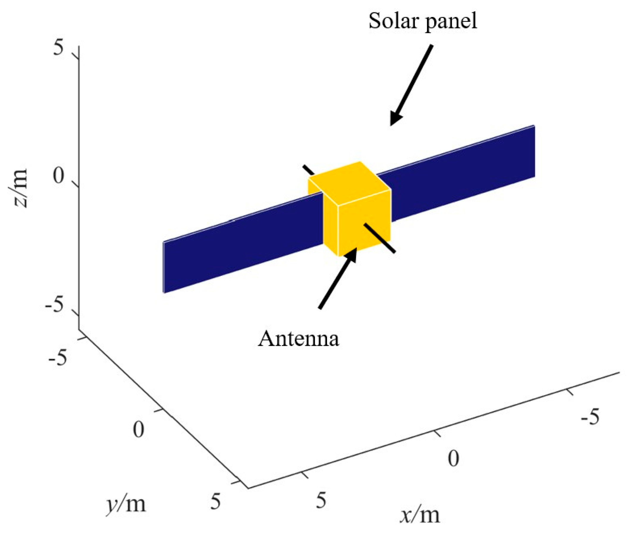
Suppose the main body of the target spacecraft is a cube of 8 cubic meters, which has two solar panels with a length of 6 m and a width of 2 m, and two antennas with a length of 2 m, as shown in Figure 3. By using equal division method, obtain 40,000 feature points data. Then, combining the K-means and EM method, calculate the key parameters of GMM. The initial parameters are listed in Table 1 and the calculation results are listed in Table 2. Because of the uniform sampling points and the regular shape of target spacecraft, the initial key parameters in Table 1 are very similar to the calculation results in Table 2.
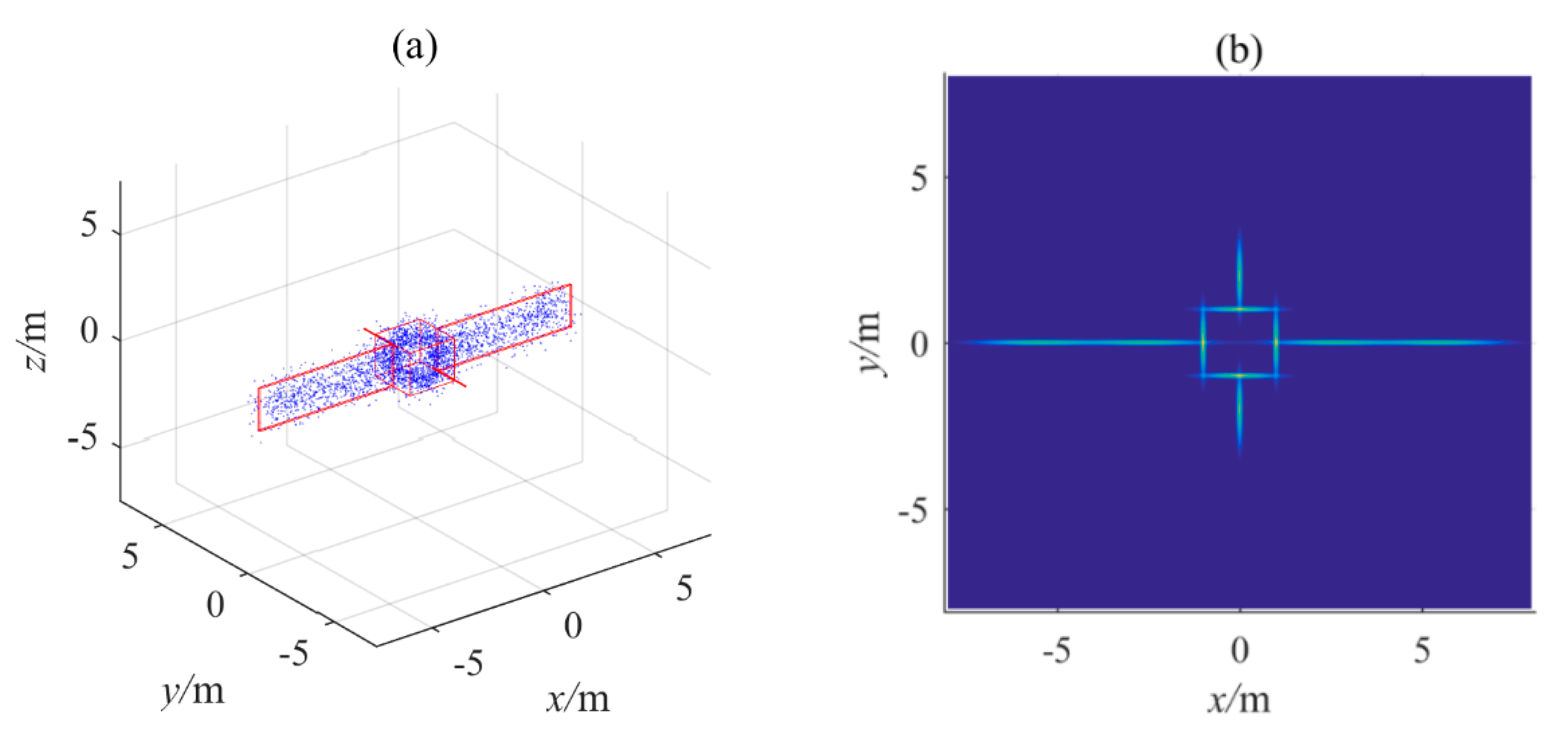
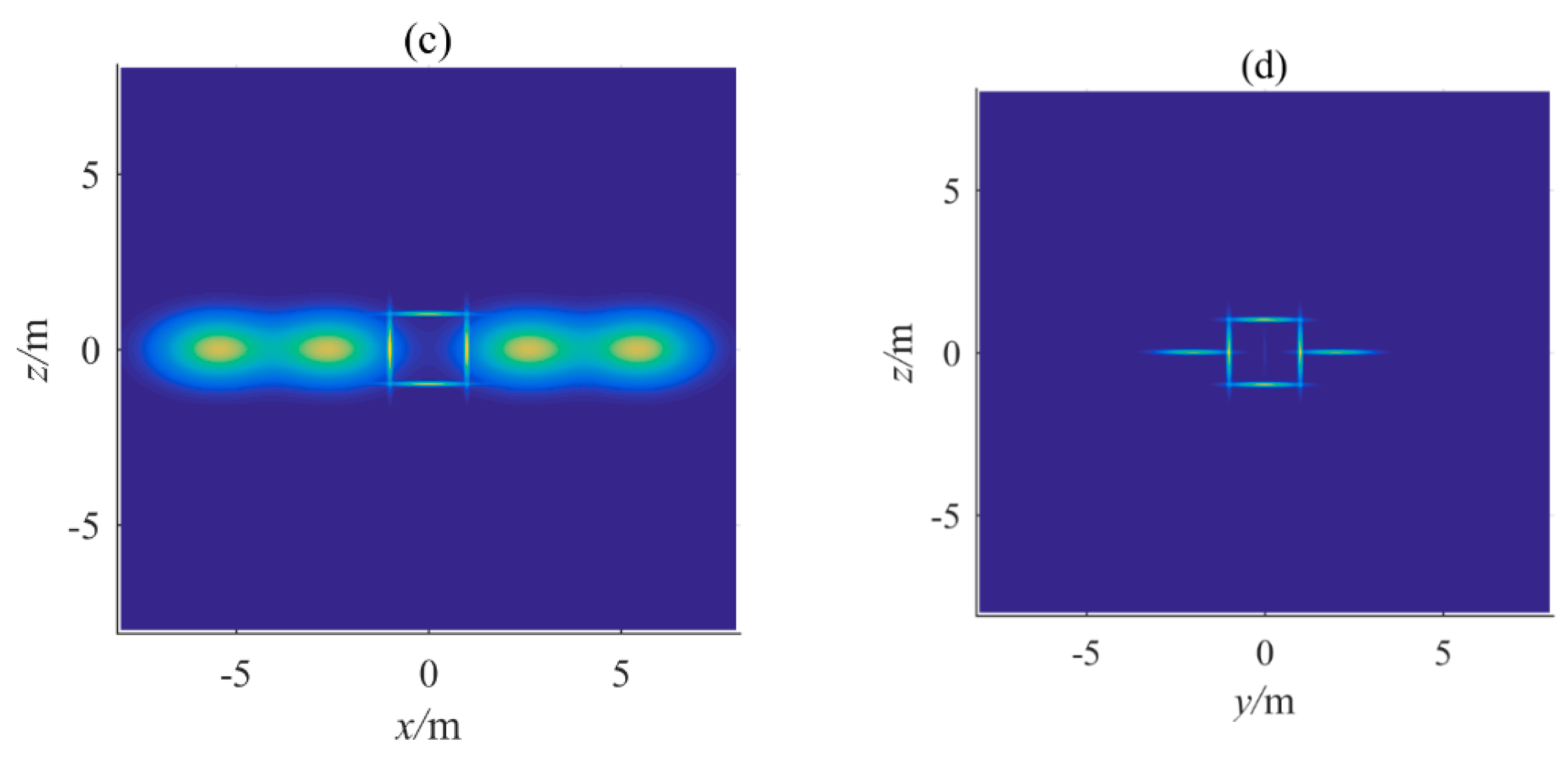
Based on the calculation results, the GMM-based reconstructed point-cloud and potential distribution are illustrated in Figure 4. Figure 4a gives the reconstructed point-cloud with additional red contours for better appearance. Figure 4b–d are the projection of GMM potential distribution in x-O-y, x-O-z, and y-O-z planes, respectively, where the brighter color means the higher potential. It is obvious that the GMM can give an accurate depiction of the complex shape of spacecraft with an analytical expression in Equation (10).
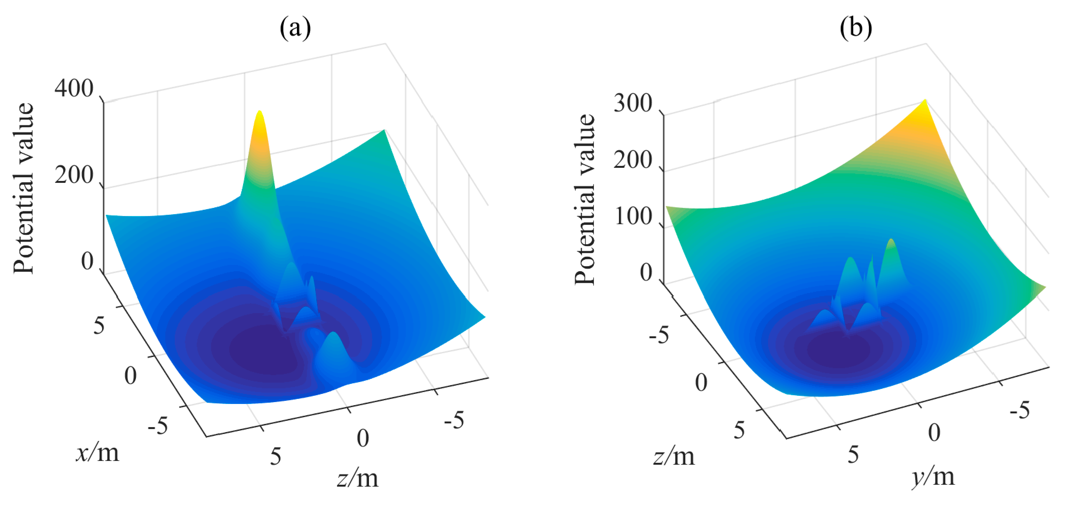
Assume that the desired position is r f = [ 2 , 2 , 2 ] T , and M = diag { 2 2 2 } , P = diag { 2 2 2 } . Then, the simulation of GMM-based artificial potential function in Equation (17) is obtained, as shown in Figure 5. The three figures show the potential of GMM-based APF in x-y, x-z and y-z 2D coordinates, respectively. It is obvious that the surface of main body and two solar panels have high potential value, as well as the two antennas. The desired position has the globally lowest potential value, equaling to zero, which means that the spatial positions away from the desired position have higher potential value. So that the service spacecraft, moving in the potential space determined by GMM-based APF, will be attracted to the desired position, as well as avoiding collision with the target spacecraft.

4.2. GMM-FTC Simulation

To implement the simulation of GMM-FTC, parameters of the controller are given in Table 3 and the orbit elements of target spacecraft are given in Table 4. The initial relative motion parameters are given in Table 5. The simulation step size is set to h = 0.1. The thruster output error is set to ±5%.
Then, the results of simulation are obtained, as shown in Figure 6, Figure 7, Figure 8 and Figure 9. Figure 6 shows the trajectory of target spacecraft from initial position (blue point), to desired position (red point) under the GMM-FTC, and the spatial relationship between target spacecraft shape and trajectory. Figure 6b is the projection of Figure 6a in x-O-y plane. It can be seen that under the GMM-FTC, the service can implement the proximity operation process while avoiding collision with any structural component of the target.
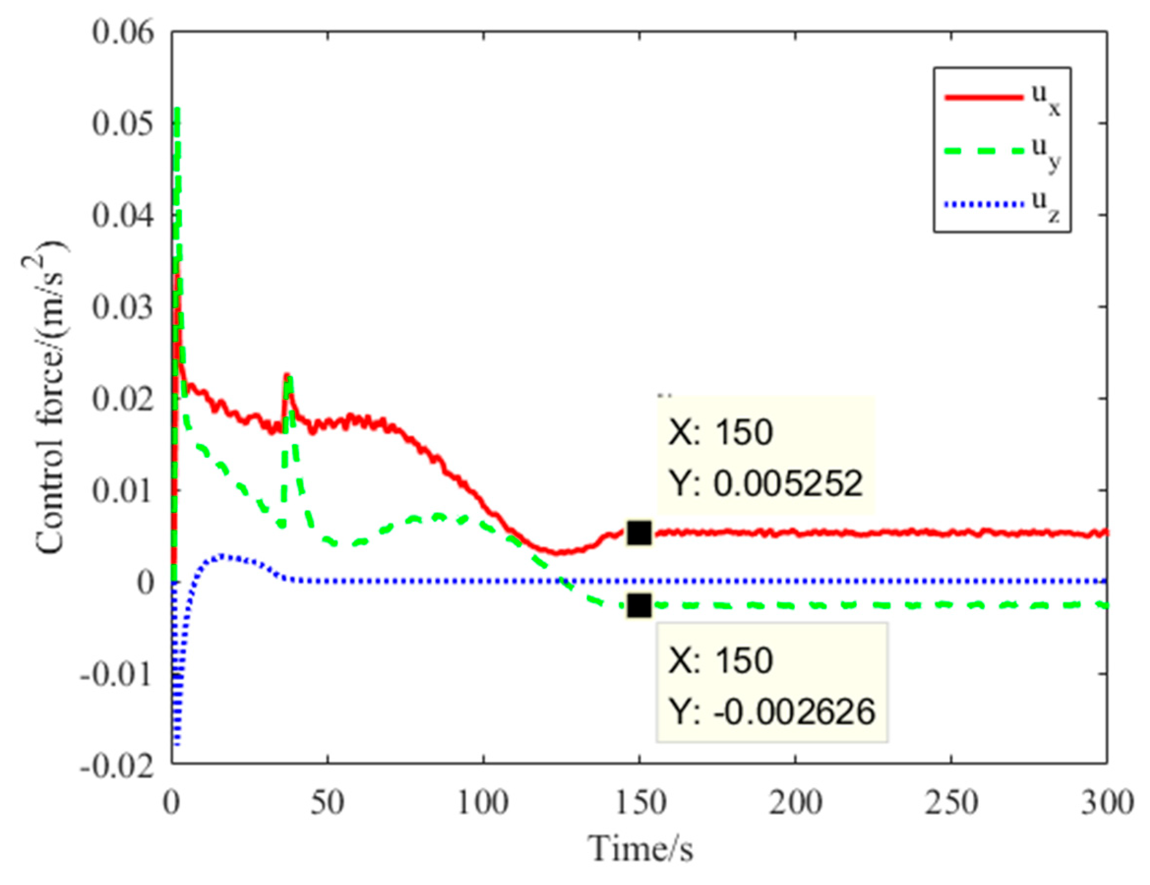
Figure 7, Figure 8 and Figure 9 are the time response of position error y 1 , velocity error y 2 , and control force u , respectively. It can be seen that these parameters converge to small regions containing zero in 150 s. The stable precision of position error is better than 1 × 10⁻⁴ m, as shown in partially enlarged view in Figure 7. From Figure 8, the amplitude of velocity is less than 0.15 m/s, which means the service keeps very low speed during proximity, which is good for improving the security. The precision is better than 1 × 10⁻⁴ m/s. From Figure 9, the amplitude of control force is less than 0.06 m/s2. Note that the control force u is stable at a constant, because the non-zero desired position vector contributes the constant force u e q as shown in Equation (9). To sum up in conclusion, under the effect of GMM-FTC, it can obtain high precision convergence, small amplitude control force, and enhanced security in the proximity operation process.
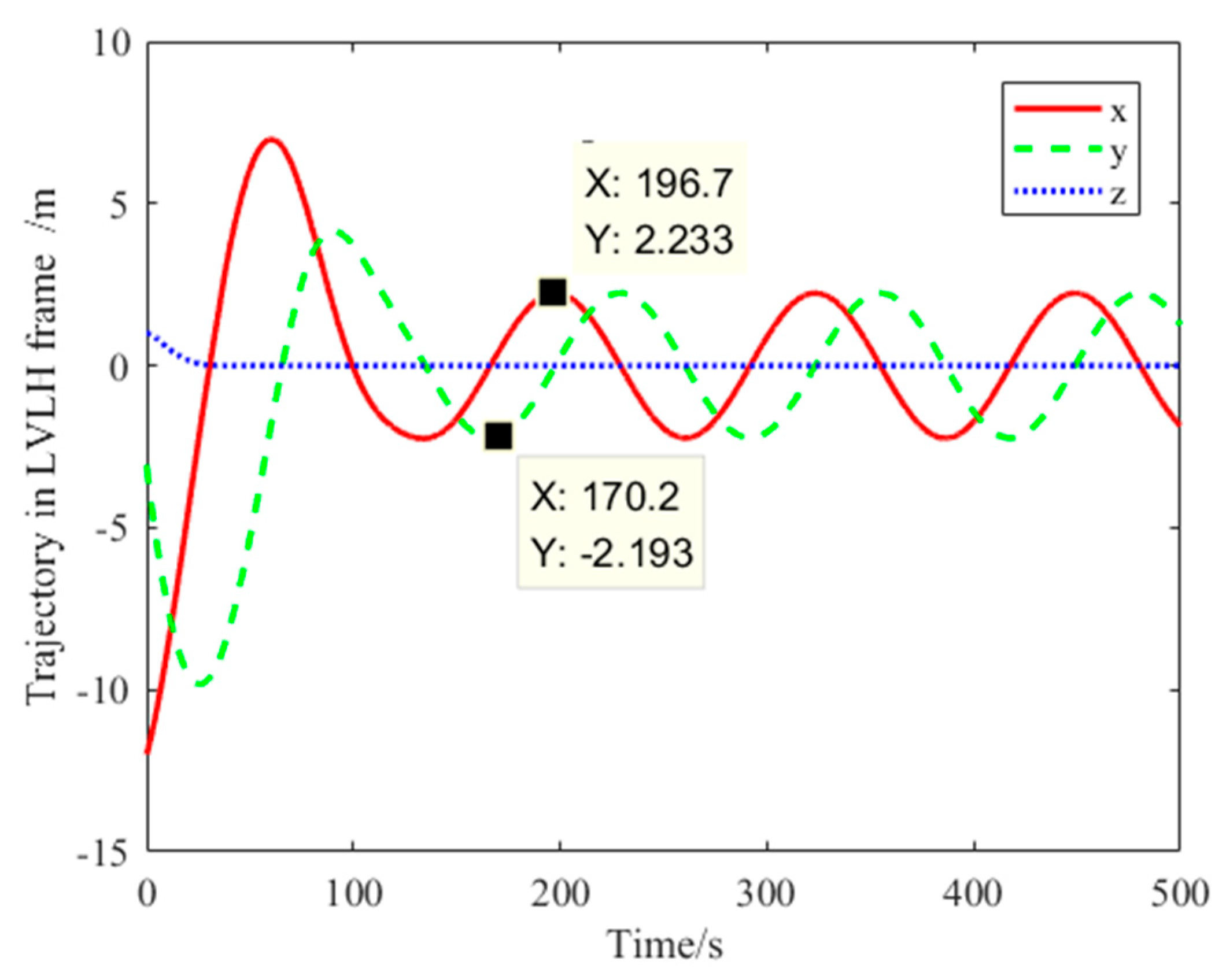
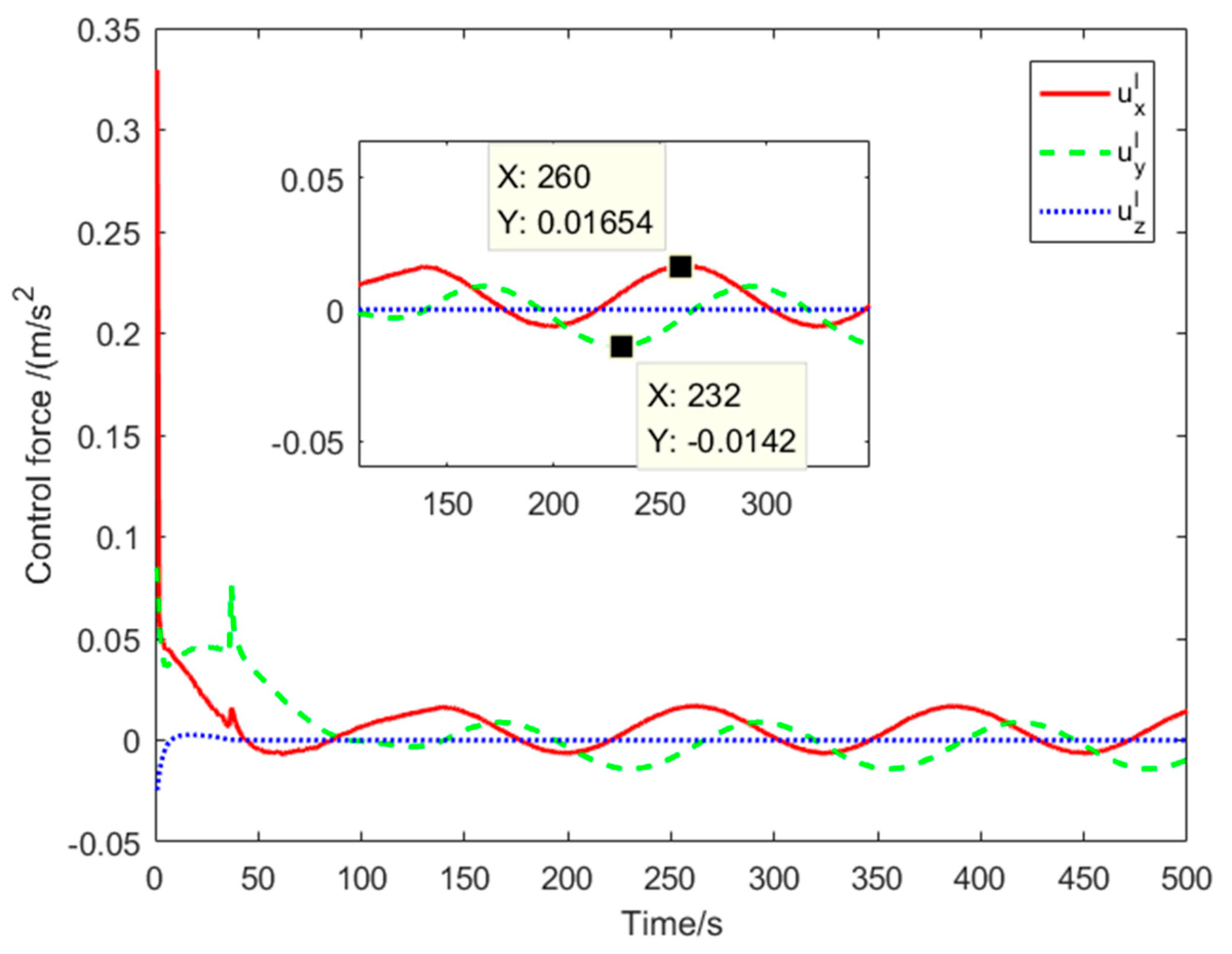
Shown Figure 6, Figure 7, Figure 8 and Figure 9 are the trajectory and state parameters in frame b . As shown below, Figure 10 and Figure 11 are the position of servicer and control force expressed in LVLH frame l , respectively. It is obvious that the servicer maintains flight around with the target after reaching the desired position in the x-O-y plane and the control force keeps oscillating to keep the servicer in the desired position.
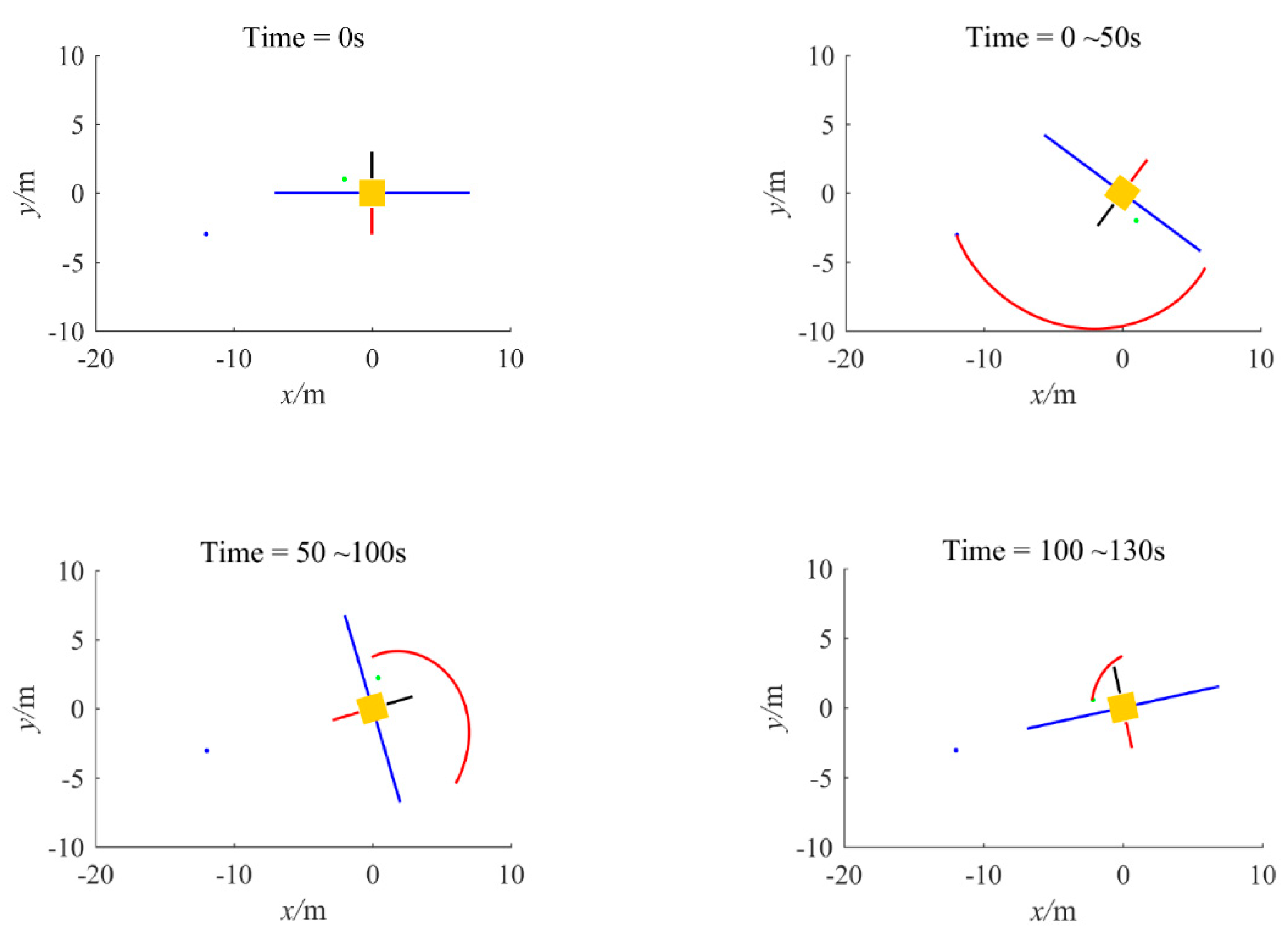
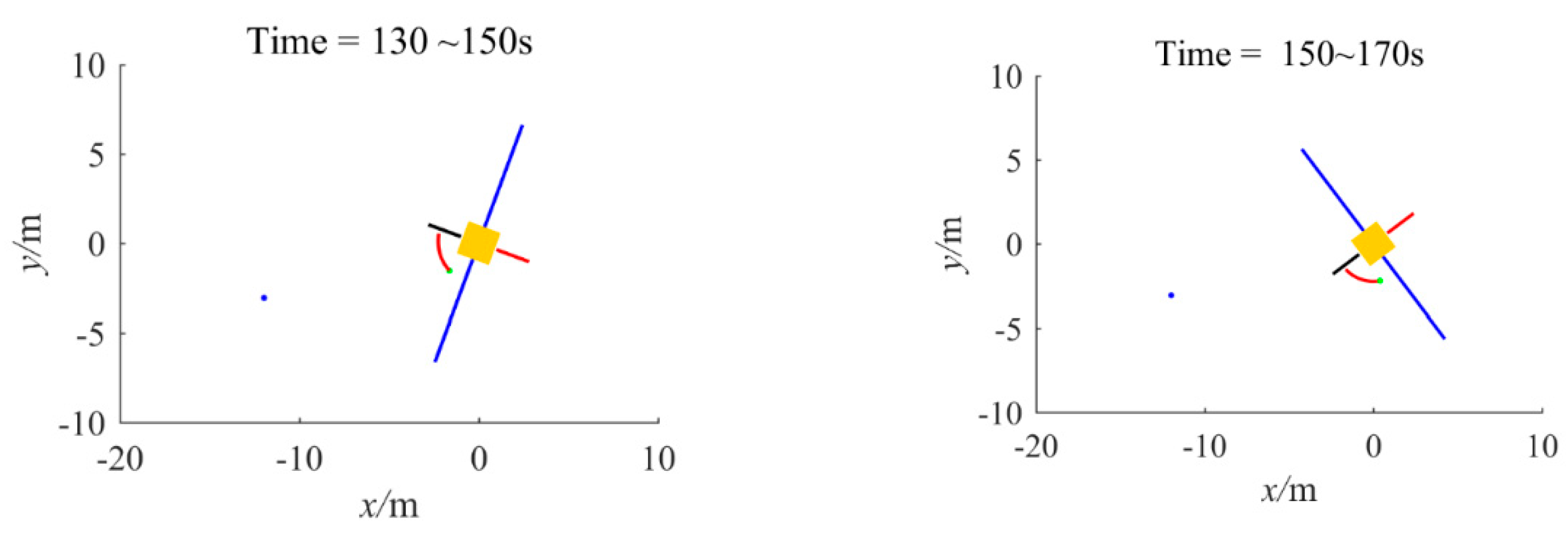
Figure 12 illustrates the trajectory of servicer and the attitude change of target in the frame l . The figures are projections in x-O-y plane. The red curve is the trajectory of the servicer, the blue and green points are the initial and time-variant desired positions, respectively. Note that one antenna is depicted by red straight line in order to better show the attitude changes of the spacecraft, i.e., counterclockwise rotation. From Figure 12, it can be seen that servicer can approach to the desired position without any collision. After 150 s, the servicer has reached the desired position and moved to the following phase. It can be seen that the servicer can follow the rotating target and keep it in the desired position well.

5. Conclusions

In this paper, a body-fixed dynamic model is derived, and the Gaussian mixture model-based fixed time controller (GMM-FTC) is proposed to solve the proximity operation problem between a service spacecraft and a target spacecraft with complex shape. The GMM is used to design a novel artificial potential function (APF) to depict the complex shape obstacle. Numerical simulations of GMM-based APF and GMM-FTC are implemented. The former results show that the potential field distribution of GMM-based APF can well meet the requirements of collision avoidance and proximity operation. The latter results show the high precision of convergence, small amplitude control force, and strengthened safety in proximity operation process.

Author Contributions

Conceptualization, methodology, analysis, R.C., Y.B., and Z.C.; writing—review and editing, R.C., Y.Z., and T.S. All authors have read and agreed to the published version of the manuscript.

Funding

This research was funded by the Major Program of National Science Foundation of China under Grant Numbers 61690210 and 61690213.

Conflicts of Interest

The authors declare no conflict of interest.

References

  1. Roscoe, C.W.T.; Westphal, J.J.; Mosleh, E. Overview and GNC design of the CubeSat Proximity Operations Demonstration (CPOD) mission. Acta Astronaut. 2018, 153, 410–421. [Google Scholar] [CrossRef]
  2. Aglietti, G.S.; Taylor, B.; Fellowes, S.; Salmon, T.; Retat, I.; Hall, A.; Chabot, T.; Pisseloup, A.; Cox, C.; Mafficini, A. The active space debris removal mission RemoveDebris. Part 2: In orbit operations. Acta Astronaut. 2020, 168, 310–322. [Google Scholar] [CrossRef] [Green Version]
  3. Biesbroek, R.; Innocenti, L.; Wolahan, A.; Serrano, S.M. e.Deorbit—ESA’s active debris removal mission. In Proceedings of the 7th European Conference on Space Debris, Darmstadt, Germany, 18–21 April 2017; p. 10. [Google Scholar]
  4. Zappulla, R.; Park, H.; Virgili-Llop, J.; Romano, M. Real-Time Autonomous Spacecraft Proximity Maneuvers and Docking Using an Adaptive Artificial Potential Field Approach. IEEE Trans. Control Syst. Technol. 2019, 27, 2598–2605. [Google Scholar] [CrossRef]
  5. McCamish, S.; Romano, M.; Yun, X. Autonomous Distributed Control Algorithm for Multiple Spacecraft in Close Proximity Operations. AIAA Guid. Navig. Control Conf. Exhib. 2007, 5, 6857. [Google Scholar]
  6. Cao, L.; Qiao, D.; Xu, J. Suboptimal artificial potential function sliding mode control for spacecraft rendezvous with obstacle avoidance. Acta Astronaut. 2018, 143, 133–146. [Google Scholar] [CrossRef]
  7. Li, Q.; Yuan, J.; Wang, H. Sliding mode control for autonomous spacecraft rendezvous with collision avoidance. Acta Astronaut. 2018, 151, 743–751. [Google Scholar] [CrossRef]
  8. Li, X. Non-cooperative autonomous rendezvous and docking using artificial potentials and sliding mode control. Proc. Inst. Mech. Eng. Part G J. Aerosp. Eng. 2019, 233, 1171–1184. [Google Scholar] [CrossRef]
  9. Zhang, J.; Ye, D.; Biggs, J.D.; Sun, Z. Finite-time relative orbit-attitude tracking control for multi-spacecraft with collision avoidance and changing network topologies. Adv. Space Res. 2019, 63, 1161–1175. [Google Scholar] [CrossRef]
  10. Dong, H.; Hu, Q.; Akella, M.R. Safety control for spacecraft autonomous rendezvous and docking under motion constraints. Caterer 2017, 207, 1680–1692. [Google Scholar] [CrossRef]
  11. Zagaris, C.; Romano, M. Reachability analysis of planar spacecraft docking with rotating body in close proximity. J. Guid. Control Dyn. 2018, 41, 1416–1422. [Google Scholar] [CrossRef]
  12. Ventura, J.; Ciarcià, M.; Romano, M.; Walter, U. Fast and near-optimal guidance for docking to uncontrolled spacecraft. J. Guid. Control Dyn. 2017, 40, 3138–3154. [Google Scholar] [CrossRef]
  13. Ma, Z.; Ma, O.; Shashikanth, B.N. Optimal control for spacecraft to rendezvous with a tumbling satellite in a close range. In Proceedings of the 2006 IEEE/RSJ International Conference on Intelligent Robots and Systems, Beijing, China, 9–15 October 2006; pp. 4109–4114. [Google Scholar]
  14. Boyarko, G.; Yakimenko, O.; Romano, M. Optimal rendezvous trajectories of a controlled spacecraft and a tumbling object. J. Guid. Control Dyn. 2011, 34, 1239–1252. [Google Scholar] [CrossRef]
  15. Xu, Z.; Chen, Y.; Xu, Z. Optimal guidance and collision avoidance for docking with the rotating target spacecraft. Adv. Space Res. 2019, 63, 3223–3234. [Google Scholar] [CrossRef]
  16. St. John-Olcayto, E.; McInnes, C.; Ankersen, F. Safety-critical autonomous spacecraft proximity operations via potential function guidance. In Proceedings of the AIAA Infotech@ Aerospace 2007 Conference and Exhibition, Chicago, IL, USA, 7–10 May 2007; p. 2895. [Google Scholar]
  17. Badawy, A.; McInnes, C.R. On-orbit assembly using superquadric potential fields. J. Guid. Control Dyn. 2008, 31, 30–43. [Google Scholar] [CrossRef] [Green Version]
  18. Feng, L.-C.; Bai, Y.-Z.; Chen, X.-Q. Collision-free trajectory planning for spacecraft close-range proximity via potential sigmoid function. J. Beijing Inst. Technol. (Engl. Ed.) 2016, 25, 43594. [Google Scholar] [CrossRef]
  19. Liu, J.; Li, H. Artificial Potential Function Safety and Obstacle Avoidance Guidance for Autonomous Rendezvous and Docking with Noncooperative Target. Math. Probl. Eng. 2019, 2019, 1–17. [Google Scholar] [CrossRef]
  20. Zhang, D.; Song, S.; Pei, R.; Duan, G. Ellipse cissoid-based potential function guidance for autonomous rendezvous and docking with non-cooperative target. J. Astronaut. 2010, 31, 2259–2268. [Google Scholar]
  21. Qing, N. Safety Guidance and Control for Spacecraft Close Proximity Maneuvers; National University of Defense Technology: Changsha, Hunan, China, 2016. [Google Scholar]
  22. Vittaldev, V.; Russell, R.P. Space Object Collision Probability Using Multidirectional Gaussian Mixture Models. J. Guid. Control Dyn. 2016, 39, 2163–2169. [Google Scholar] [CrossRef]
  23. Vishwajeet, K.; Singla, P. Adaptive Split/Merge-Based Gaussian Mixture Model Approach for Uncertainty Propagation. J. Guid. Control Dyn. 2018, 41, 603–617. [Google Scholar] [CrossRef]
  24. Vittaldev, V.; Russell, R.P.; Linares, R. Spacecraft uncertainty propagation using Gaussian mixture models and Polynomial chaos expansions. J. Guid. Control Dyn. 2016, 39, 2615–2626. [Google Scholar] [CrossRef] [Green Version]
  25. Rommel, C.; Bonnans, F.; Martinon, P.; Gregorutti, B. Gaussian mixture penalty for trajectory optimization problems. J. Guid. Control Dyn. 2019, 42, 1857–1862. [Google Scholar] [CrossRef]
  26. Eckart, B. Compact Generative Models of Point Cloud Data for 3D Perception. Ph.D. Thesis, Carnegie Mellon University Pittsburgh, Pittsburgh, PA, USA, 2017. [Google Scholar]
  27. Wang, G.; Schultz, L.; Qi, J. Statistical Image Reconstruction for Muon Tomography Using a Gaussian Scale Mixture Model. IEEE Trans. Nucl. Sci. 2009, 56, 2480–2486. [Google Scholar] [CrossRef]
  28. Wang, Y.; Bai, Y.; Xing, J.; Radice, G.; Ni, Q.; Chen, X. Equal-collision-probability-curve method for safe spacecraft close-range proximity maneuvers. Adv. Space Res. 2018, 62, 2599–2619. [Google Scholar] [CrossRef]
  29. Wang, Y.; Chen, X.; Dechao, R.; Yangwei, O.; Qing, N.; Yuzhu, B. Multi-Equal-Collision-Probability-Cure Method for Convex Polygon-shape Spacecraft Safe Proximity Manoeuvres. J. Navig. 2019, 72, 405–429. [Google Scholar]
  30. Liu, Y.; Liu, X.-P.; Li, X.-H. Survey on finite-time control for nonlinear systems. Control Theory Appl. 2020, 37, 1–12. [Google Scholar]
  31. Polyakov, A. Nonlinear feedback design for fixed-time stabilization of linear control systems. IEEE Trans. Autom. Control 2012, 57, 2106–2110. [Google Scholar] [CrossRef] [Green Version]
  32. Zuo, Z.; Han, Q.-L.; Ning, B. An Overview of Recent Advances in Fixed-Time Cooperative Control of Multiagent Systems. IEEE Trans. Ind. Inform. 2018, 14, 2322–2334. [Google Scholar] [CrossRef]
  33. Liu, X.; Liao, X. Fixed-time stabilization control for port-Hamiltonian systems. Nonlinear Dyn. 2019, 96, 1497–1509. [Google Scholar] [CrossRef]
  34. Chen, Q.; Xie, S.; Sun, M.; He, X. Adaptive Nonsingular Fixed-Time Attitude Stabilization of Uncertain Spacecraft. IEEE Trans. Aerosp. Electron. Syst. 2018, 54, 2937–2950. [Google Scholar] [CrossRef]
  35. Jiang, B.; Hu, Q.; Friswell, M.I. Fixed-Time Attitude Control for Rigid Spacecraft With Actuator Saturation and Faults. IEEE Trans. Control Syst. Technol. 2016, 24, 1892–1898. [Google Scholar] [CrossRef]
  36. Shi, X.-N.; Zhang, Y.-A.; Zhou, D.; Zhou, Z.-G. Global fixed-time attitude tracking control for the rigid spacecraft with actuator saturation and faults. Acta Astronaut. 2019, 155, 325–333. [Google Scholar] [CrossRef]
  37. Ton, C.; Petersen, C. Continuous Fixed-Time Sliding Mode Control for Spacecraft with Flexible Appendages. IFAC-Pap. 2018, 51, 1–5. [Google Scholar] [CrossRef]
  38. Sun, Y.; Zhao, W.; Li, C.; Li, D.; Ma, G. Hovering control for spacecraft in relative orbit based on fixed-time stabilization theory. J. Harbin Inst. Technol. 2016, 48, 26–31. [Google Scholar]
  39. Hu, Q.; Chen, W.; Guo, L. Fixed-Time Maneuver Control of Spacecraft Autonomous Rendezvous With a Free-Tumbling Target. IEEE Trans. Aerosp. Electron. Syst. 2019, 55, 562–577. [Google Scholar] [CrossRef]
  40. Huang, Y.; Jia, Y. Adaptive Fixed-Time Six-DOF Tracking Control for Noncooperative Spacecraft Fly-Around Mission. IEEE Trans. Control Syst. Technol. 2019, 27, 1796–1804. [Google Scholar] [CrossRef]
  41. Tschauner, J.; Hempel, P. Optimale beschleunigungsprogramme fur das rendezvous-manover. Astronaut. Acta. 1964, 10, 296–307. [Google Scholar]
  42. Clohessy, W.; Wiltshire, R. Terminal guidance system for satellite rendezvous. J. Aerosp. Sci. 1960, 27, 653–658. [Google Scholar] [CrossRef]
  43. Dempster, A.P.; Laird, N.M.; Rubin, D.B. Maximum likelihood from incomplete data via the EM algorithm. J. R. Stat. Soc. Ser. B (Methodol.) 1977, 39, 1–22. [Google Scholar]
  44. Li, B. An Experiment of K-Means Initialization Strategies on Handwritten Digits Dataset. Intell. Inf. Manag. 2018, 10, 43–48. [Google Scholar]
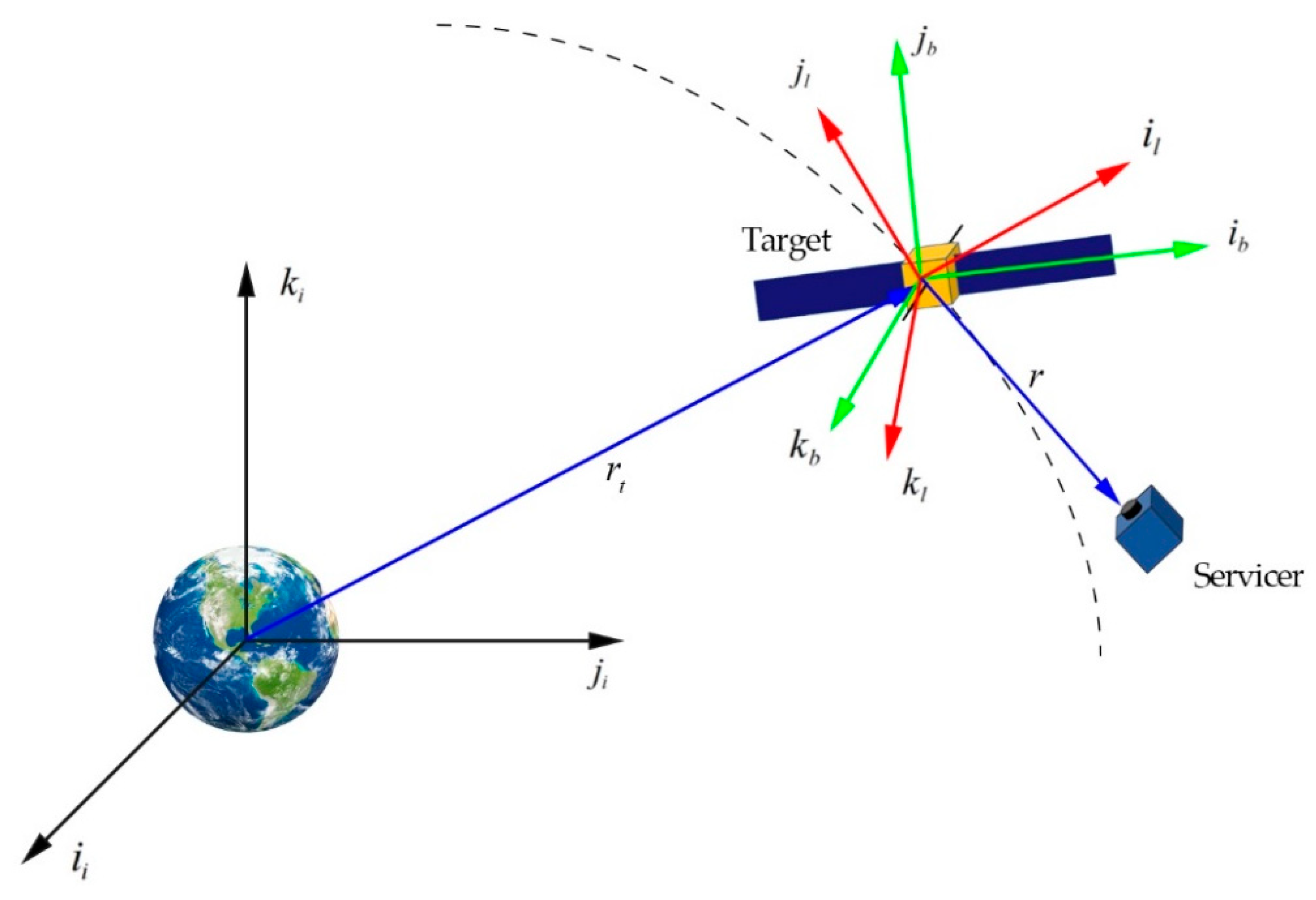
Figure 1. Mission scenario and three different coordinate frames.
Applsci 10 05986 g001
Figure 2. Flowchart of the two-spacecraft proximity operation process.
Applsci 10 05986 g002
Figure 3. Complex shape of target spacecraft.
Applsci 10 05986 g003
Figure 4. The GMM-based reconstructed point-cloud and potential distribution. (a) Reconstructed point-cloud of the target shape; (b) the projection of GMM-based potential distribution in x-O-y plane; (c) the projection of GMM-based potential distribution in x-O-z plane; (d) the projection of GMM-based potential distribution in y-O-z plane.
Applsci 10 05986 g004aApplsci 10 05986 g004b
Figure 5. The potential distribution of GMM-based artificial potential function. (a) The potential of GMM-based APF in x-y coordinate; (b) the potential of GMM-based APF in x-z coordinate; (c) the potential of GMM-based APF in y-z coordinate.
Applsci 10 05986 g005aApplsci 10 05986 g005b
Figure 6. The proximity trajectory to target spacecraft. (a) The trajectory in 3D coordinates; (b) the projection of trajectory in the x-O-y plane.
Applsci 10 05986 g006
Figure 7. Time response of position error r r f .
Applsci 10 05986 g007
Figure 8. Time response of velocity error r ˙ r ˙ f .
Applsci 10 05986 g008
Figure 9. Time response of control force u .
Applsci 10 05986 g009
Figure 10. Time response of relative position in local vertical local horizontal (LVLH) frame.
Applsci 10 05986 g010
Figure 11. Time response of control force u l .
Applsci 10 05986 g011
Figure 12. The servicer’s trajectory and the target’s attitude change.
Applsci 10 05986 g012aApplsci 10 05986 g012b
Table 1. The initial key parameters of Gaussian mixture model (GMM).
j π j μ j Σ j
18.302 × 10⁻² [ 1 0 0 ] T diag { 0 0.3301 0.3301 }
28.302 × 10⁻² [ 1 0 0 ] T diag { 0 0.3302 0.3301 }
38.302 × 10⁻² [ 0 1 0 ] T diag { 0.3300 0 0.3302 }
48.302 × 10⁻² [ 0 1 0 ] T diag { 0.3301 0 0.3299 }
58.302 × 10⁻² [ 0 0 1 ] T diag { 0.3301 0.3300 0 }
68.302 × 10⁻² [ 0 0 1 ] T diag { 0.3300 0.3300 0 }
74.193 × 10⁻⁴ [ 0 2 0 ] T diag { 0 0.3350 0 }
84.193 × 10⁻⁴ [ 0 2 0 ] T diag { 0 0.3350 0 }
91.256 × 10⁻¹ [ 2.5 0 0 ] T diag { 0.7550 0 0.3300 }
101.252 × 10⁻¹ [ 2.5 0 0 ] T diag { 0.7500 0 0.3300 }
111.252 × 10⁻¹ [ 5.5 0 0 ] T diag { 0.7500 0 0.3300 }
121.252 × 10⁻¹ [ 5.5 0 0 ] T diag { 0.7500 0 0.3300 }
Table 2. Calculation results of key parameters of GMM.
j π j μ j Σ j
18.295 × 10⁻² [ 1 0 0 ] T diag { 1 × 10 5 0.3303 0.3300 }
28.295 × 10⁻² [ 1 0 0 ] T diag { 1 × 10 5 0.3303 0.3300 }
38.302 × 10⁻² [ 0 1 0 ] T diag { 0.3300 1 × 10 5 0.3300 }
48.302 × 10⁻² [ 0 1 0 ] T diag { 0.3301 1 × 10 5 0.3300 }
58.300 × 10⁻² [ 0 0 1 ] T diag { 0.3299 0.3301 1 × 10 5 }
68.302 × 10⁻² [ 0 0 1 ] T diag { 0.3300 0.3301 1 × 10 5 }
74.196 × 10⁻⁴ [ 0 2.0043 0 ] T diag { 1 × 10 5 0.3382 1 × 10 5 }
84.196 × 10⁻⁴ [ 0 2.0043 0 ] T diag { 1 × 10 5 0.3382 1 × 10 5 }
91.287 × 10⁻¹ [ 2.5886 0 0 ] T diag { 0.9601 1 × 10 5 0.3301 }
101.279 × 10⁻¹ [ 2.5886 0 0 ] T diag { 0.9489 1 × 10 5 0.3301 }
111.221 × 10⁻¹ [ 5.4843 0 0 ] T diag { 0.8751 1 × 10 5 0.3300 }
121.225 × 10⁻¹ [ 5.4811 0 0 ] T diag { 0.8776 1 × 10 5 0.3300 }
Table 3. Parameters of Gaussian mixture model-fixed-time control (GMM-FTC).
ParametersValue
α 1 diag{3 × 10⁻¹ 3 × 10⁻¹ 3 × 10⁻¹}
β 1 diag{1 × 10⁻² 1 × 10⁻² 1 × 10⁻²}
ζ 1 0.6
ζ 2 1.5
λ 1 diag{5 × 10⁻² 5 × 10⁻² 5 × 10⁻²}
λ 2 diag{1 × 10⁻² 1 × 10⁻² 1 × 10⁻²}
k s diag{3 × 10⁻⁴ 1.0 × 10⁻⁴ 1.0 × 10⁻⁴}
Mdiag{6 × 10⁻¹ 6 × 10⁻¹ 4 × 10⁻¹}
Pdiag{8 × 10⁻¹ 8 × 10⁻¹ 8 × 10⁻¹}
Table 4. Orbit elements of the target spacecraft.
ElementsValueUnits
Semi-major axis, a6878.14 km
Eccentricity, e0.01
Inclination, i45 deg
Longitude of the ascending node, Ω 0 deg
Argument of perigee, ω 0 deg
Initial true anomaly, σ 0 0 deg
Table 5. Initial relative motion parameters expressed in frame b .
ParametersValueUnits
Initial relative position, r ( 0 ) [ 12 3 1 ] T m
Initial relative velocity, r ˙ ( 0 ) [ 0 0 0 ] T m/s
Desired relative position, r f [ 2 1 0 ] T m
Desired relative velocity, r ˙ f [ 0 0 0 ] T m/s
Angular velocity of target spacecraft, ω b [ 0 0 0.05 ] T rad/s
Angular acceleration of target spacecraft, ω ˙ b [ 0 0 0 ] T rad/s2
Initial attitude of target spacecraft, σ ( 0 ) [ 0 0 0 ] T rad