Dispersion Analysis of Periodically Loaded Transmission Lines with Twist Symmetry Using the Mode-Matching Technique

 , , , , and
Abstract
:1. Introduction
2. Problem Formulation
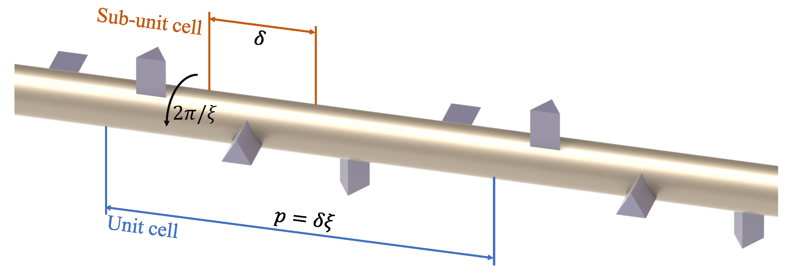
2.1. Description of the Analyzed Structures
2.2. Enforcement of Symmetry and Periodicity
2.3. Obtaining Using the Mode-Matching Technique
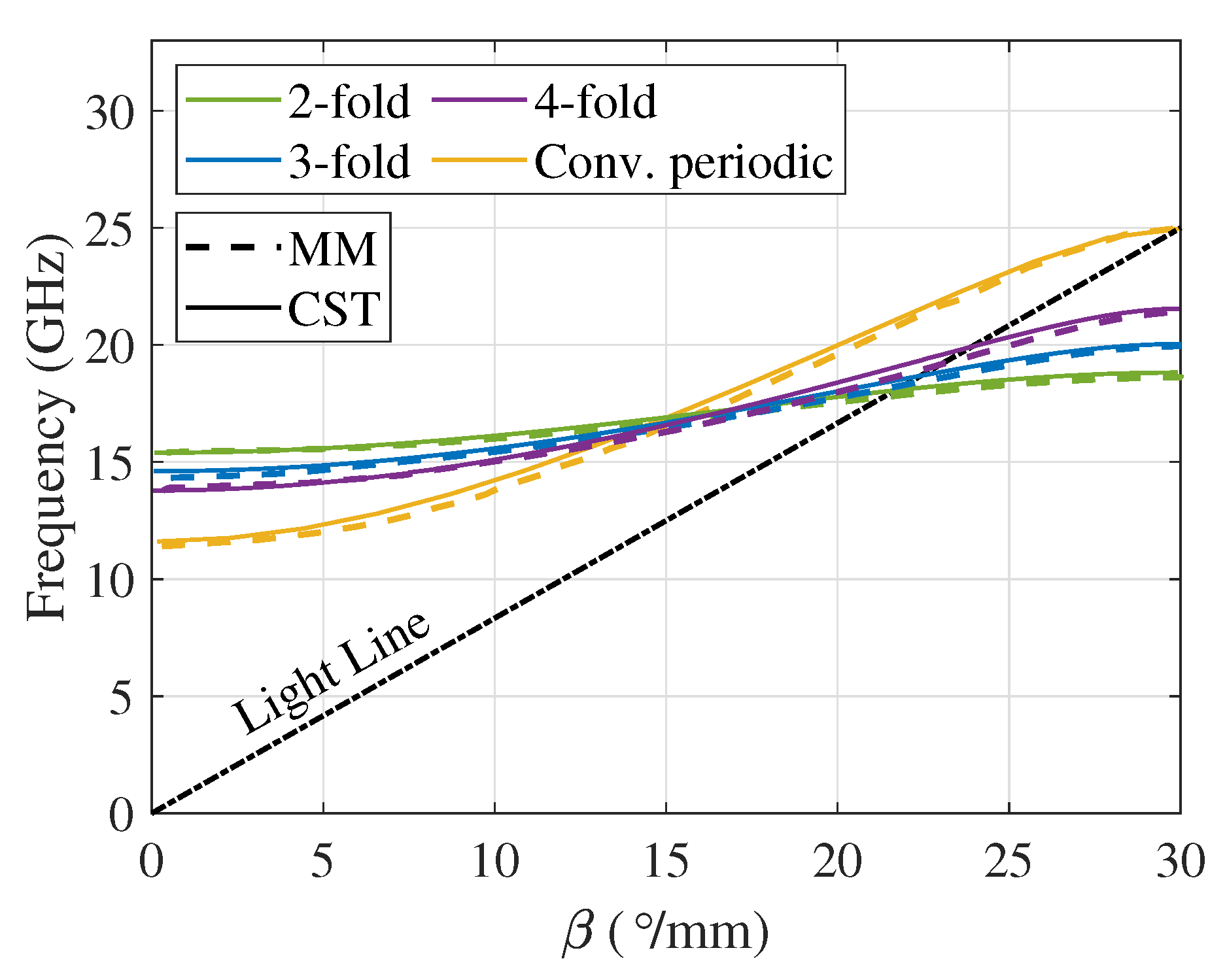
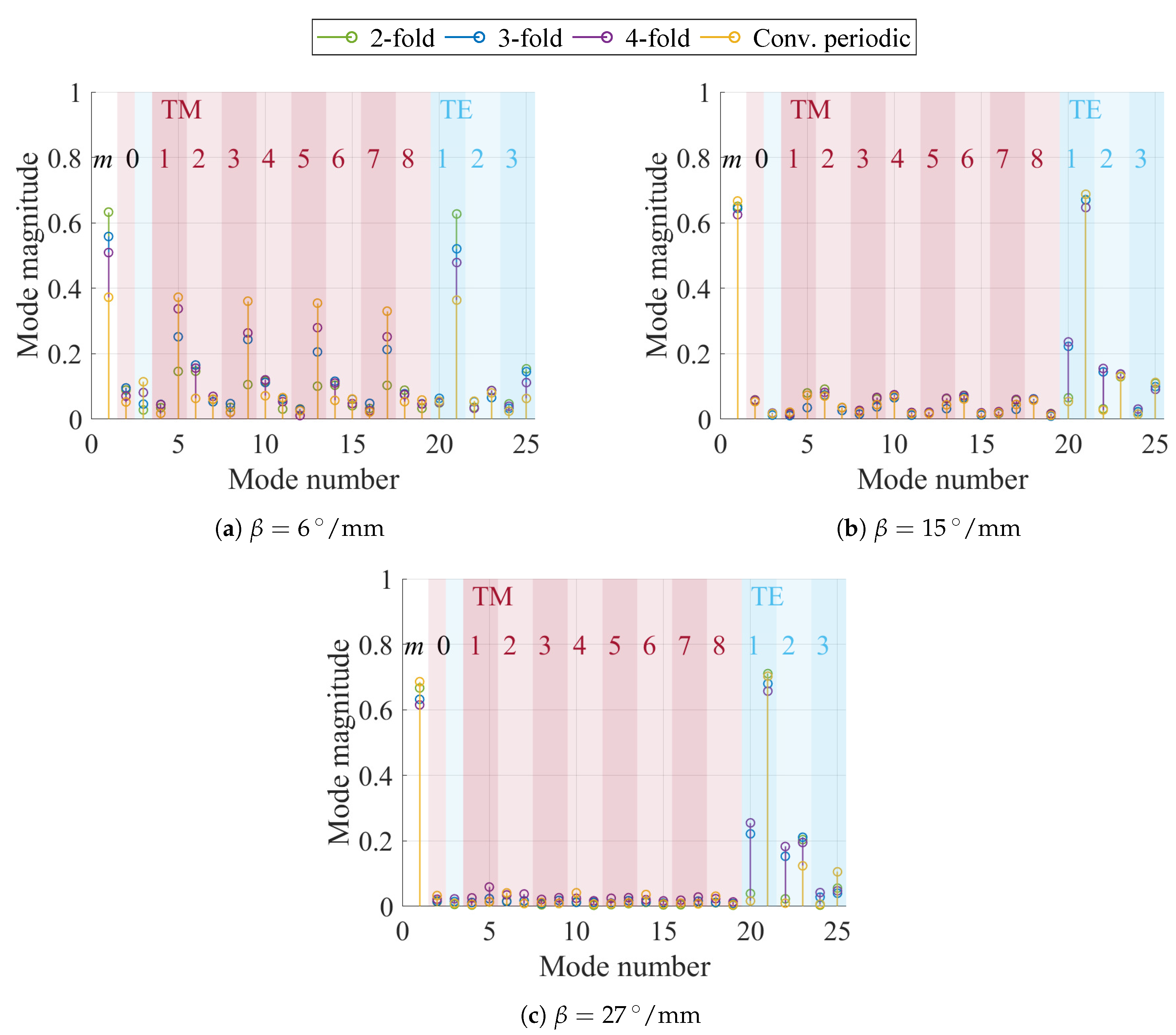
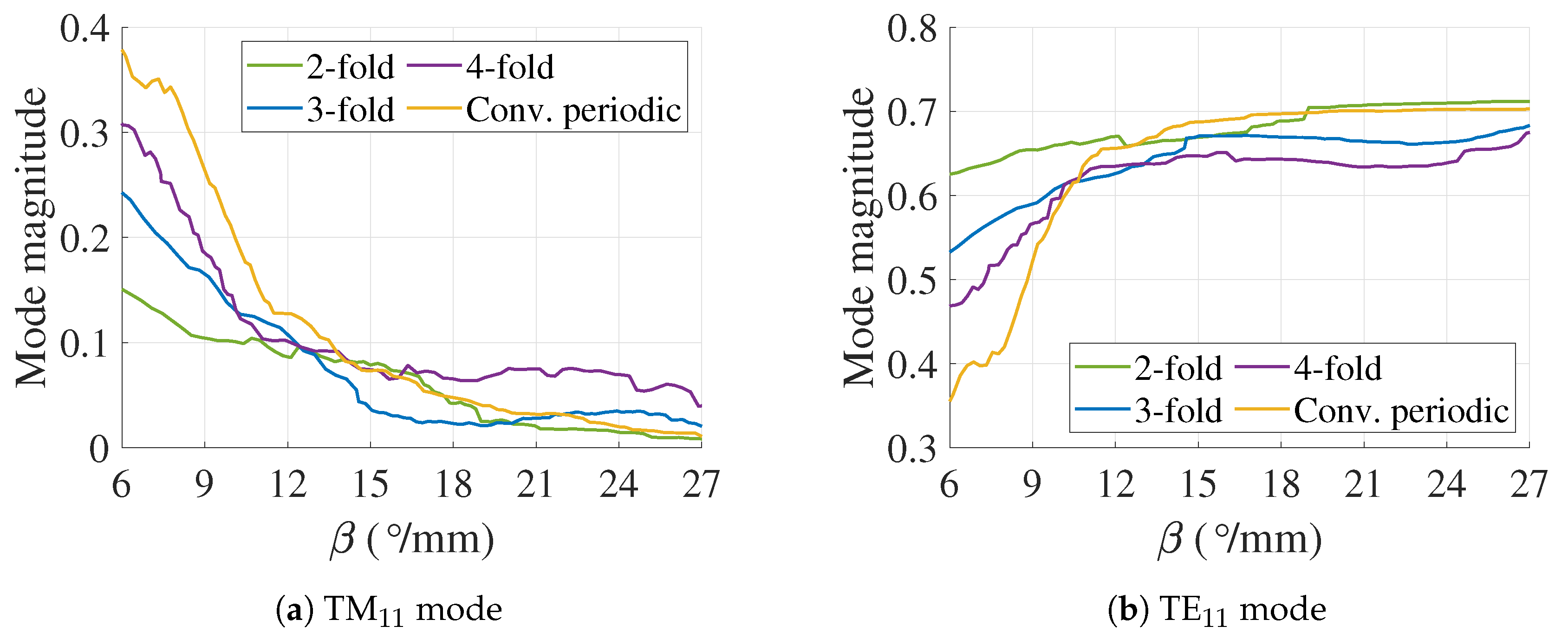
3. Results
4. Conclusions
Author Contributions
Funding
Conflicts of Interest
Appendix A
References
- Sharp, E.D. A High-Power Wide-Band Waffle-Iron Filter. IEEE Trans. Microw. Theory Tech. 1963, 11, 111–116. [Google Scholar] [CrossRef]
- Pous, R.; Pozar, D.M. A frequency-selective surface using aperture-coupled microstrip patches. IEEE Trans. Antennas Propag. 1991, 39, 1763–1769. [Google Scholar] [CrossRef]
- Faenzi, M.; Minatti, G.; González-Ovejero, D.; Caminita, F.; Martini, E.; Della Giovampaola, C.; Maci, S. Metasurface Antennas: New Models, Applications and Realizations. Sci. Rep. 2019, 9, 10178. [Google Scholar] [CrossRef] [PubMed] [Green Version]
- Liu, X.; Fan, K.; Shadrivov, I.V.; Padilla, W.J. Experimental realization of a terahertz all-dielectric metasurface absorber. Opt. Express 2017, 25, 191–201. [Google Scholar] [CrossRef] [PubMed]
- Bosiljevac, M.; Casaletti, M.; Caminita, F.; Sipus, Z.; Maci, S. Non-Uniform Metasurface Luneburg Lens Antenna Design. IEEE Trans. Antennas Propag. 2012, 60, 4065–4073. [Google Scholar] [CrossRef]
- Crepeau, P.J.; McIsaac, P.R. Consequences of Symmetry in Periodic Structures. Proc. IEEE 1963, 52, 33–43. [Google Scholar] [CrossRef] [Green Version]
- Mittra, R.; Laxpati, S. Propagation in a Wave Guide with Glide Reflection Symmetry. Can. J. Phys. 1965, 43, 353–372. [Google Scholar] [CrossRef]
- Kieburtz, R.; Impagliazzo, J. Multimode Propagation on Radiating Traveling-Wave Structures with Glide-Symmetric Excitation. IEEE Trans. Antennas Propag. 1970, 18, 3–7. [Google Scholar] [CrossRef]
- Hessel, A.; Chen, M.H.; Li, R.C.M.; Oliner, A.A. Propagation in Periodically Loaded Waveguides with Higher Symmetries. Proc. IEEE 1973, 61, 183–195. [Google Scholar] [CrossRef]
- Ghasemifard, F. Periodic Structures with Higher Symmetries: Analysis and Applications. Ph.D. Thesis, KTH Royal Institute of Technology, Stockholm, Sweden, 2018. [Google Scholar]
- Quesada, R.; Martín-Cano, D.; García-Vidal, F.; Bravo-Abad, J. Deep-Subwavelength Negative-Index Waveguiding Enabled By Coupled Conformal Surface Plasmons. Opt. Lett. 2014, 39, 2990–2993. [Google Scholar] [CrossRef]
- Quevedo-Teruel, O.; Ebrahimpouri, M.; Ng Mou Kehn, M. Ultrawideband Metasurface Lenses Based on Off-Shifted Opposite Layers. IEEE Antennas Wirel. Propag. Lett. 2016, 15, 484–487. [Google Scholar] [CrossRef]
- Arnberg, P.; Barreira Petersson, O.; Zetterstrom, O.; Ghasemifard, F.; Quevedo-Teruel, O. High Refractive Index Electromagnetic Devices in Printed Technology Based on Glide-Symmetric Periodic Structures. Appl. Sci. 2020, 10, 3216. [Google Scholar] [CrossRef]
- Chang, T.; Kim, J.U.; Kang, S.K.; Kim, H.; Kim, D.K.; Lee, Y.H.; Shin, J. Broadband giant-refractive-index material based on mesoscopic space-filling curves. Nat. Commun. 2016, 7, 12661. [Google Scholar] [CrossRef] [PubMed] [Green Version]
- Cavallo, D.; Felita, C. Analytical formulas for artificial dielectrics with nonaligned layers. IEEE Trans. Antennas Propag. 2017, 65, 5303–5311. [Google Scholar] [CrossRef]
- Cavallo, D. Dissipation Losses in Artificial Dielectric Layers. IEEE Trans. Antennas Propag. 2018, 66, 7460–7465. [Google Scholar] [CrossRef] [Green Version]
- Ebrahimpouri, M.; Herran, L.F.; Quevedo-Teruel, O. Wide-Angle Impedance Matching Using Glide-Symmetric Metasurfaces. IEEE Microw. Wirel. Compon. Lett. 2020, 30, 8–11. [Google Scholar] [CrossRef]
- Ebrahimpouri, M.; Quevedo-Teruel, O. Ultrawideband Anisotropic Glide-Symmetric Metasurfaces. IEEE Antennas Wirel. Propag. Lett. 2019, 18, 1547–1551. [Google Scholar] [CrossRef]
- Quevedo-Teruel, O.; Miao, J.; Mattsson, M.; Algaba-Brazalez, A.; Johansson, M.; Manholm, L. Glide-Symmetric Fully Metallic Luneburg Lens for 5G Communications at Ka-Band. IEEE Antennas Wirel. Propag. Lett. 2018, 17, 1588–1592. [Google Scholar] [CrossRef]
- Fan, F.; Cai, M.; Zhang, J.; Yan, Z.; Wu, J. Wideband Low-Profile Luneburg Lens Based on a Glide-Symmetric Metasurface. IEEE Access 2020, 8, 85698–85705. [Google Scholar] [CrossRef]
- Alex-Amor, A.; Ghasemifard, F.; Valerio, G.; Ebrahimpouri, M.; Padilla, P.; Fernandez-Gonzalez, J.M.; Quevedo-Teruel, O. Glide-Symmetric Metallic Structures with Elliptical Holes for Lens Compression. IEEE Trans. Microw. Theory Techn. 2020. [Google Scholar] [CrossRef]
- Bantavis, P.; Gonzalez, C.G.; Sauleau, R.; Goussetis, G.; Tubau, S.; Legay, H. Broadband graded index Gutman lens with a wide field of view utilizing artificial dielectrics: A design methodology. Opt. Express 2020, 28, 14648–14661. [Google Scholar] [CrossRef] [PubMed]
- Ebrahimpouri, M.; Quevedo-Teruel, O.; Rajo-Iglesias, E. Design Guidelines for Gap Waveguide Technology Based on Glide-Symmetric Holey Structures. IEEE Microw. Wirel. Compon. Lett. 2017, 27, 542–544. [Google Scholar] [CrossRef]
- Ebrahimpouri, M. High Frequency Microwave and Antenna Devices Based on Transformation Optics and Glide-Symmetric Metasurfaces. Ph.D. Thesis, KTH Royal Institute of Technology, Stockholm, Sweden, 2019. [Google Scholar]
- Mouris, B.A.; Fernández-Prieto, A.; Thobaben, R.; Martel, J.; Mesa, F.; Quevedo-Teruel, O. On the Increment of the Bandwidth of Mushroom-Type EBG Structures With Glide Symmetry. IEEE Trans. Microw. Theory Tech. 2020, 68, 1365–1375. [Google Scholar] [CrossRef]
- Ebrahimpouri, M.; Rajo-Iglesias, E.; Sipus, Z.; Quevedo-Teruel, O. Cost-Effective Gap Waveguide Technology Based on Glide-Symmetric Holey EBG Structures. IEEE Trans. Microw. Theory Tech. 2018, 66, 927–934. [Google Scholar] [CrossRef] [Green Version]
- Monje-Real, A.; Fonseca, N.J.G.; Zetterstrom, O.; Pucci, E.; Quevedo-Teruel, O. Holey Glide-Symmetric Filters for 5G at Millimeter-Wave Frequencies. IEEE Microw. Wirel. Compon. Lett. 2020, 30, 31–34. [Google Scholar] [CrossRef]
- Ebrahimpouri, M.; Brazalez, A.A.; Manholm, L.; Quevedo-Teruel, O. Using Glide-Symmetric Holes to Reduce Leakage between Waveguide Flanges. IEEE Microw. Wirel. Compon. Lett. 2018, 28, 473–475. [Google Scholar] [CrossRef]
- He, Z.; An, S.; Liu, J.; Jin, C. Variable High Precision Wide D-band Phase Shifter. IEEE Access 2020, 8, 140438–140444. [Google Scholar] [CrossRef]
- Valerio, G.; Sipus, Z.; Grbic, A.; Quevedo-Teruel, O. Accurate Equivalent-Circuit Descriptions of Thin Glide-Symmetric Corrugated Metasurfaces. IEEE Trans. Antennas Propag. 2017, 65, 2695–2700. [Google Scholar] [CrossRef] [Green Version]
- Chen, Q.; Ghasemifard, F.; Valerio, G.; Quevedo-Teruel, O. Modeling and Dispersion Analysis of Coaxial Lines With Higher Symmetries. IEEE Trans. Microw. Theory Tech. 2018, 66, 1–8. [Google Scholar] [CrossRef]
- Valerio, G.; Ghasemifard, F.; Sipus, Z.; Quevedo-Teruel, O. Glide-Symmetric All-Metal Holey Metasurfaces for Low-Dispersive Artificial Materials: Modeling and Properties. IEEE Trans. Microw. Theory Tech. 2018, 66, 1–14. [Google Scholar] [CrossRef] [Green Version]
- Ghasemifard, F.; Norgren, M.; Quevedo-Teruel, O. Dispersion Analysis of 2-D Glide-Symmetric Corrugated Metasurfaces Using Mode-Matching Technique. IEEE Microw. Wirel. Compon. Lett. 2018, 28, 1–3. [Google Scholar] [CrossRef]
- Ghasemifard, F.; Norgren, M.; Quevedo-Teruel, O.; Valerio, G. Analyzing Glide-Symmetric Holey Metasurfaces Using a Generalized Floquet Theorem. IEEE Access 2018, 6, 71743–71750. [Google Scholar] [CrossRef]
- Alex-Amor, A.; Valerio, G.; Ghasemifard, F.; Mesa, F.; Padilla, P.; Fernandez-Gonzalez, J.M.; Quevedo-Teruel, O. Wave Propagation in Periodic Metallic Structures with Equilateral Triangular Holes. Appl. Sci. 2020, 10, 1600. [Google Scholar] [CrossRef] [Green Version]
- Mesa, F.; Rodríguez-Berral, R.; Medina, F. On the computation of the dispersion diagram of symmetric one-dimensionally periodic structures. Symmetry 2018, 10, 307. [Google Scholar] [CrossRef] [Green Version]
- Bagheriasl, M.; Quevedo-Teruel, O.; Valerio, G. Bloch Analysis of Artificial Lines and Surfaces Exhibiting Glide Symmetry. IEEE Trans. Microw. Theory Tech. 2019, 67, 2618–2628. [Google Scholar] [CrossRef] [Green Version]
- Mesa, F.; Valerio, G.; Rodríguez-Berral, R.; Quevedo-Teruel, O. Simulation-Assisted Efficient Computation of the Dispersion Diagram of Periodic Structures. IEEE Antennas Propag. Mag. 2020, 1–11, to be published. [Google Scholar]
- Dahlberg, O.; Mitchell-Thomas, R.; Quevedo-Teruel, O. Reducing the Dispersion of Periodic Structures with Twist and Polar Glide Symmetries. Sci. Rep. 2017, 7, 10136. [Google Scholar] [CrossRef]
- Ghasemifard, F.; Norgren, M.; Quevedo-Teruel, O. Twist and Polar Glide Symmetries: An Additional Degree of Freedom to Control The Propagation Characteristics of Periodic Structures. Sci. Rep. 2018, 8, 11266. [Google Scholar] [CrossRef] [Green Version]
- Dahlberg, O.; Ghasemifard, F.; Valerio, G.; Quevedo-Teruel, O. Propagation characteristics of periodic structures possessing twist and polar glide symmetries. EPJ Appl. Metamat. 2019, 6, 14. [Google Scholar] [CrossRef] [Green Version]
- Quevedo-Teruel, O.; Dahlberg, O.; Valerio, G. Propagation in Waveguides with Transversal Twist-Symmetric Holey Metallic Plates. IEEE Microw. Wirel. Compon. Lett. 2018, 28, 1–3. [Google Scholar] [CrossRef]
- Palomares-Caballero, A.; Padilla, P.; Alex-Amor, A.; Valenzuela-Valdes, J.; Quevedo-Teruel, O. Twist and glide symmetries for helix antenna design and miniaturization. Symmetry 2019, 11, 349. [Google Scholar] [CrossRef] [Green Version]
- Dahlberg, O.; Valerio, G.; Quevedo-Teruel, O. Fully Metallic Flat Lens Based on Locally Twist-Symmetric Array of Complementary Split-Ring Resonators. Symmetry 2019, 11, 581. [Google Scholar] [CrossRef] [Green Version]
- Kopp, V.I.; Churikov, V.M.; Singer, J.; Chao, N.; Neugroschl, D.; Genack, A.Z. Chiral Fiber Gratings. Science 2004, 305, 74–75. [Google Scholar] [CrossRef] [PubMed]
- Bagheriasl, M.; Valerio, G. Bloch Analysis of Electromagnetic Waves in Twist-Symmetric Lines. Symmetry 2019, 11, 620. [Google Scholar] [CrossRef] [Green Version]
- CST Microwave Studio, Version 2019. Available online: http://www.cst.com/ (accessed on 19 July 2020).
- Pozar, D.M. Microwave Engineering; John Wiley & Sons: Hoboken, NJ, USA, 1998; pp. 163–170. [Google Scholar]
- Matlab, Version 2020. Available online: https://se.mathworks.com/ (accessed on 19 July 2020).


© 2020 by the authors. Licensee MDPI, Basel, Switzerland. This article is an open access article distributed under the terms and conditions of the Creative Commons Attribution (CC BY) license (http://creativecommons.org/licenses/by/4.0/).
Share and Cite
Zetterstrom, O.; Valerio, G.; Mesa, F.; Ghasemifard, F.; Norgren, M.; Quevedo-Teruel, O. Dispersion Analysis of Periodically Loaded Transmission Lines with Twist Symmetry Using the Mode-Matching Technique. Appl. Sci. 2020, 10, 5990. https://doi.org/10.3390/app10175990
Zetterstrom O, Valerio G, Mesa F, Ghasemifard F, Norgren M, Quevedo-Teruel O. Dispersion Analysis of Periodically Loaded Transmission Lines with Twist Symmetry Using the Mode-Matching Technique. Applied Sciences. 2020; 10(17):5990. https://doi.org/10.3390/app10175990
Chicago/Turabian StyleZetterstrom, Oskar, Guido Valerio, Francisco Mesa, Fatemeh Ghasemifard, Martin Norgren, and Oscar Quevedo-Teruel. 2020. "Dispersion Analysis of Periodically Loaded Transmission Lines with Twist Symmetry Using the Mode-Matching Technique" Applied Sciences 10, no. 17: 5990. https://doi.org/10.3390/app10175990