Article

Numerical Modeling of Particles Separation Method Based on Compound Electric Field

1
School of Mechatronic Engineering and Automation, Shanghai University, Shanghai 200444, China
2
Henan Institute of Metrology, Xinxiang 450000, China
*
Authors to whom correspondence should be addressed.
Appl. Sci. 2020, 10(17), 5999; https://doi.org/10.3390/app10175999
Submission received: 10 July 2020 / Revised: 19 August 2020 / Accepted: 26 August 2020 / Published: 29 August 2020
(This article belongs to the Section Mechanical Engineering)

Abstract

:
This paper shows the results of simulation of features and usability of a proposed method for particle matter (PM) separation detection based on composite electric field. Considering the composite electric field and drag coefficient, a nonlinear dynamic model of particle separation is established. Meanwhile, the model takes into account the changes in the dynamic model caused by the different diameters and different speeds of the particles, and uses the effect of the composite electric field to separate the PM. Numerical simulation results show that the PM diameter, electric field strength, and drag force have significant effects on the separation of particles. Among them, as the drag force decreases, the particle separation displacement gradually increases, and the electric field affects the particle separation direction. In the acceleration room, the particle velocity increases with the increasing of the electric field strength. In the separation room, the displacement of the particulate matter in the Y-axis direction gradually increases from a negative displacement to a positive displacement as the electric field strength increases. The displacement forms a bow shape. When the drag coefficient is changed, the displacement will suddenly increase while it is lower than a certain value. Considering the change of electric field and drag force at the same time, the separation effect would be more obvious when the drag coefficient is smaller. The electric field strength affects the separation direction of the particulate matter.

1. Introduction

The atmosphere is one of the natural environments on which human beings depend. Atmospheric pollution seriously harms human health, destroys the ecological environment, and hinders the sustainable development of cities and regions. Air pollution, especially fine particulate matter, has caused a series of concerns about air quality. Airborne particulate matter is a key indicator of air pollution. It consists of extremely small particles and droplets containing mineral dust, inorganic salts, organic acids, organic chemicals, metals and soil, or dust particles [1]. Although there are many ways to define particle matter (PM), aerodynamic parameters are one of the main criteria for describing the transmission capacity of PM in the atmosphere or its absorption capacity through respiratory organs [2]. Fine particles can be suspended in the atmosphere for a long time, and spread in the atmosphere for a long distance. Fine particles, less than 2.5 μm in size, can enter and exist in the secondary respiratory system (bronchial and alveolar) to produce serious respiratory diseases such as chronic asthma, emphysema, lung cancer [3,4]. Different atmospheric particles can cause different diseases [5,6,7,8]. The World Health Organization estimates that about 2 million people die from atmospheric particulate pollution [9].
Atmospheric particulate matter is considered to be one of the most dangerous pollutants due to its impact on climate and health. The separation of atmospheric particulate matter plays an important role in the entire detection process and is the core of the atmospheric particulate matter detection system. Atmospheric particulate matter is easy to produce large fluctuations due to its light weight and small particle diameter. Separation accuracy has always been the difficulty of atmospheric particle detection. A series of outdoor PM2.5 monitoring projects have been carried out worldwide [10,11,12].
Traditional methods usually rely on professional air quality monitoring stations operated by national or local environmental protection architectures. However, the monitoring station is very large and complicated to operate, and cannot be deployed at high density. There are currently some commercial instruments for PM detection, but they are usually expensive, bulky, and relatively complicated to use [13,14]. In recent years, various methods of reducing the size and cost of the monitoring system have been reported. Light scattering technology is the most commonly used indirect method in PM quality testing [15,16]. However, due to the drastic decrease of the Brillouin scattering cross section with the particle diameter, light scattering technology has a typical lower size limit of detection of 0.5 µm [17]. Luca Lombardo et al. [18] proposed a distributed optical sampling system for atmospheric particulates, but there is a lower detection limit due to the filter screen. Sound waves have excellent sensitivity and have been used for particle detection [19], however, acoustic sensors are highly affected by environmental conditions such as humidity, pressure, and temperature. In addition, the detection of silicon resonant cantilever beams has been developed for the detection of nanoparticles in the air [20,21]. However, its quality resolution and quality measurement uniformity are unsatisfactory. Dynamic analysis was also performed [22,23]. In addition, the combination of thermocompression resonance and aerosol inertial impact was also used for size separation and mass measurement of air particles with relatively uniform mass sensitivity [24,25].
The method using virtual instrument has real-time classification ability [26], which has been widely used in particle classification. However, it needs to assemble with other parts for separation and detection of airborne particles, which may bring assembly tolerance. Ling-Jyh Chen et al. [27] proposed an anomaly detection framework (ADF) suitable for large real environment sensing systems, but it can only detect anomalies. Yong Wang et al. [28] introduced a miniaturized particle separation and detection system based on 3D printed virtual impactor (VI) and quartz crystal microsphere (QCM) sensor, but its measurement range was relatively small. Y Zhang et al. [29] studied the separation behavior of the original silicon in the high-silicon aluminum-silicon melt during directional solidification under alternating electromagnetic fields, at different frequencies and pulling speeds. Kai Guo et al. [30] used an electromagnetic cooperative oil–water separation experiment system to study the spatial distribution, electric field, and the sequence of magnetic field action on oil–water separation. There was little research on particle separation using electric or magnetic fields. In this paper, a particle separation detection method based on the composite electric field is proposed. After corona discharge, particles with different diameters are charged with different charges. Then, the atmospheric particles can be separated by using the idea that the particles with different charges have different trajectories under multiple field forces. Compared with the manual weighing method, β-ray attenuation method, and oscillation balance method, the operation is simple, less time-consuming, and does not need high environmental requirements. The composite electric field refers to the entire electric field in the separation room, which is distributed in three areas. Each area is composed of a different electric field. Under the action of multiple fields, the separation of atmospheric particles can be achieved. In this paper, the diameter of the particles, the electric field, and drag force are studied to discuss the effect on the separation of particles. It has been found that it is feasible to separate particles of different diameters by reducing the drag force and increasing the electric field intensity. This paper first establishes the dynamic model of particulate matter in the compound electric field, then numerically solves and analyzes the separation effect of particulate matter, and finally gives the conclusion that the proposed method, by reducing drag and increasing electric field intensity, is a viable separation method.

2. Atmospheric Particulate Matter Separation Principle

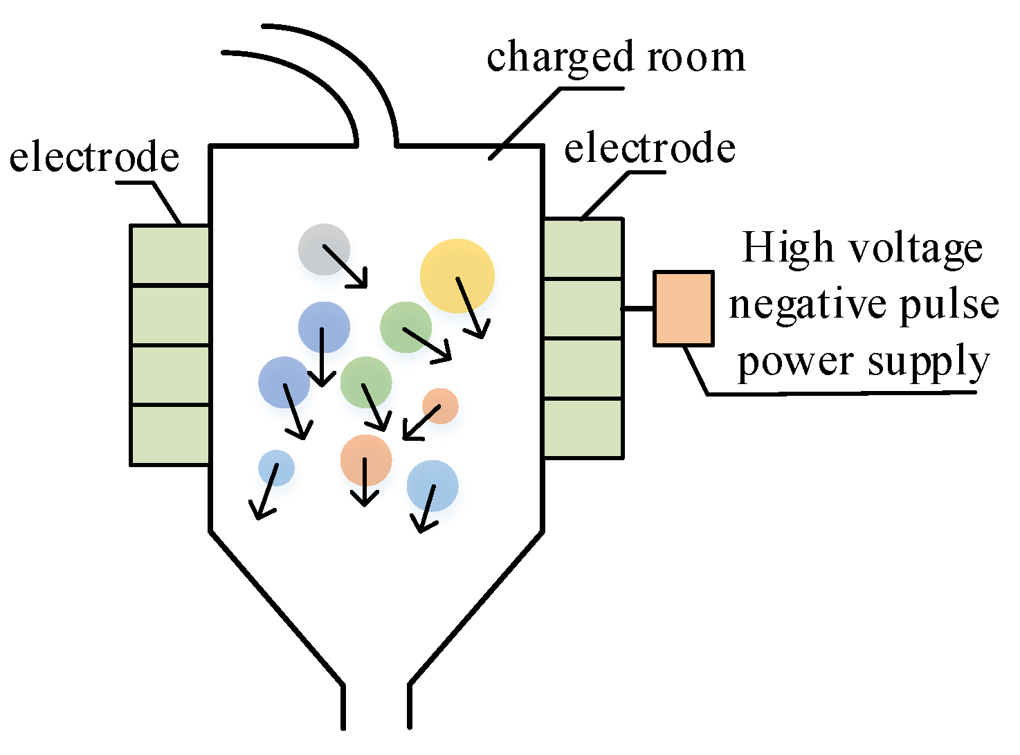
The working principle of atmospheric particulate separation matter based on the compound electric field is shown in Figure 1. The separation system is mainly composed of air inlet, charge room, acceleration room, and separation room. Firstly, the particles enter the room at a speed from the entrance. In the charge room, the anode corona discharge ionizes the air, producing a lot of free electrons and ions. As the particles pass through the ionization zone, electrons are attached to the particles, which make the particles charged by collision and diffusion, and finally reach a saturated state [31]. Then the particles slowly enter the acceleration room, all of them are accelerated by the electric field. Finally, the particles enter the separation room, and particles of different diameters carry different charges. Through the action of the composite electric field, their motion trajectories are different. Therefore, the separation of particulate matter can be achieved.
In the charge room, the particles enter a space where a large amount of ions and electrons exist, and the charges are obtained by collision and diffusion, and reach a saturated state. The diffusion charges are derived from the thermal motion of the particles. The principle is shown in Figure 2. The particles gain total charge can be defined by [31]:
q 0 = 3 ε r ε r + 2 π ε 0 d p 2 E 0 + 2 π ε 0 d p k T q ε l n ( 1 + q ε 2 N 0 d p 2 ε 0 2 m π k T t ) ,
where εr is relative dielectric constant; ε0 is vacuum dielectric constant; dp is particle diameter; E0 is electric field intensity in the charged region; k is Boltzmann constant; qε is unit charge; T is absolute temperature; m is the mass of the particle; N0 is the number of space ions; t is particle movement time.
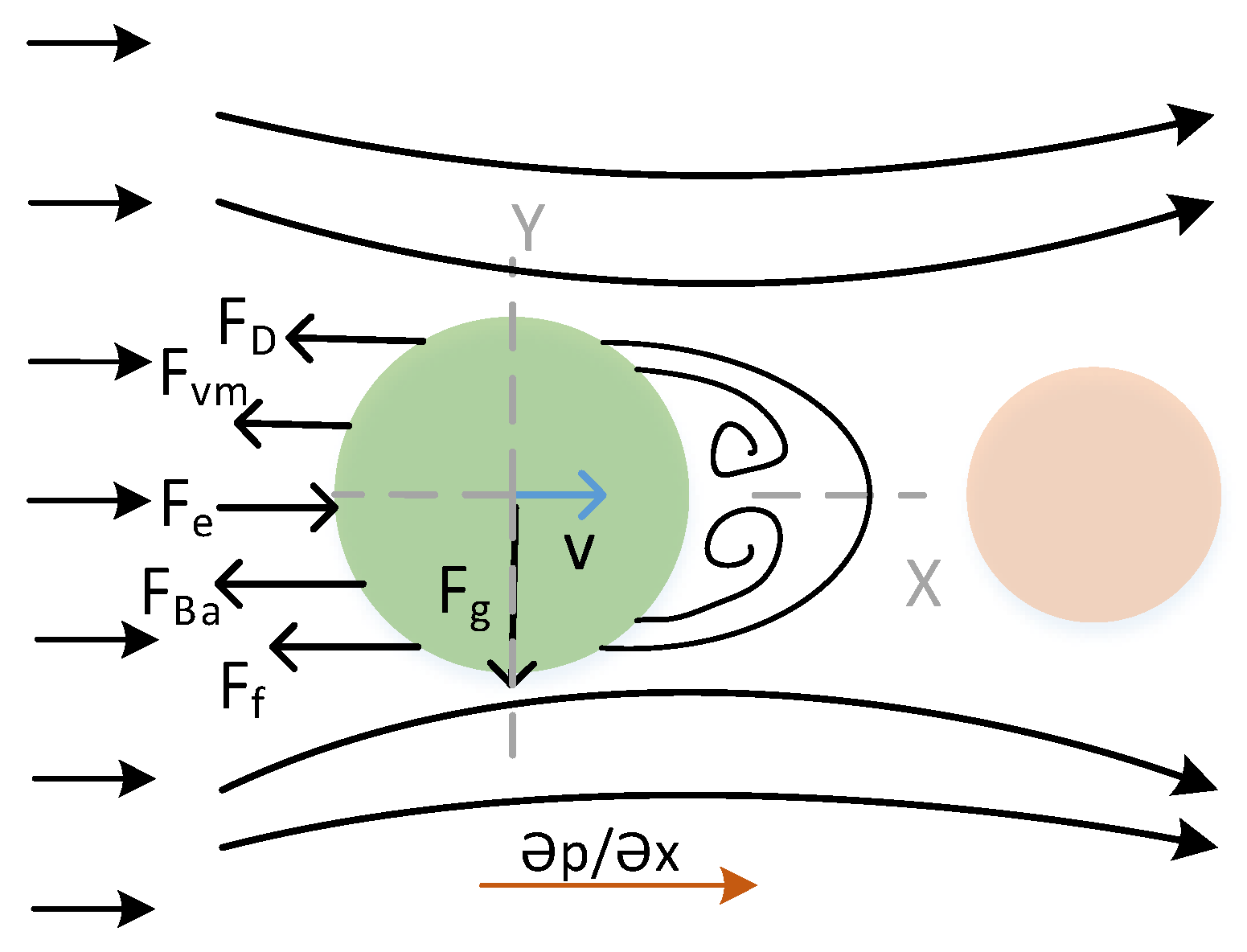
In the acceleration room, the force between the particles is very small, as atmospheric particles are relatively sparse and the distance between particles is large. Therefore, interactions between particles can be ignored. In the gas–solid two-phase flow, particles are subjected to drag, Basset force, encapsulation mass force, gravity and electric field force, and move under the action of various forces.
In a gas–solid two-phase flow, the definition and measurement of the drag force at different stages are critical. The drag force of particles is defined by [32]:
F D = 1 8 π d p 2 ρ g C D | v p v g | ( v p v g ) ,
{ C D = 24 R e t ,             R e t < 2 C D = 18.5 R e t 0.6 ,             2 < R e t < 500 C D = 0.44 ,             R e t > 500 ,
R e t = | v p v g | d p ρ g μ g ,
where CD is drag coefficient; Ret is the particle Reynolds number; ρg is air density; vg is gas velocity; vp is particle velocity; μg is hydrodynamic viscosity.
As the particles accelerate first and then drive the surrounding fluid to accelerate, the Bassett force is produced by the viscous effect of the fluid. In the acceleration room, charged particles are accelerated. When the acceleration is large, the Basset forces become important. When particles are accelerating in a stationary fluid, the Bassett force can be derived according to the Stokes region. When the particle Reynolds number exceeds the range of the Stokes region, the Bassett force needs to be corrected by introducing a correction factor:
F B = 9 M a d p μ v 0 t v / t t τ d τ ,
F B = 9 d p ρ g ρ p μ π C B 0 t d d t ( v v p ) t τ d τ ,
where Ma is the mass of the particle; CB is Bassett force correction coefficient.
When the particle accelerates, it is going to drive the fluid around it. There is a secondary flow around the particle. The fluid also accelerates, and the force accelerating the fluid being driven is the additional mass force. According to Newton’s third law, this force also prevents particles from moving. It is defined by [32]:
F A = 1 2 M a v t .
Obviously, particles are also affected by the field forces, including the gravitational fields and electric fields. Finally, the charged particles move under the action of multiple forces.

3. Dynamic Model Based on Composite Electric Field Separation Method

In order to investigate the effect of composite electric field method on the separation of fine particles, the force on the particle is considered in the plane. It is assumed that the particles are spherical, and the electric field is evenly distributed.
When the particles accelerate in the acceleration room, we need to change the type of drag on the particles according to a different Reynolds number. Since the particles enter the acceleration room at a very slow speed, the Reynolds number is calculated according to particle size and velocity. When the particle velocity is slow, the particle is first in the Stokes region and then changes according to the state. The force patterns at different stages in the acceleration zone are shown in Figure 3. In the Stokes region, that is Ret < 2, the force on particles is as follows:
M a = ρ p π 6 d p 3 ,
where ρp is particle density.
Introducing Equations (1), (3)–(9) into Equation (2), we can get the dynamic equations as follows, and the subsequent power q0 is calculated from Equation (1):
π 6 d p 3 ρ p y ¨ p = 3 π μ d p ( v ˙ p v g ) π 12 d p 3 ρ g d d t ( y ˙ p v g ) 3 2 d p 2 π ρ g μ 0 t d d τ ( y ˙ p v g ) t τ d τ   + 4 π 3 d p 3 ρ p g + q 0 E
In the acceleration room, the air is in a static state, and vg = 0; When calculating the Basset force, the particle acceleration is assumed to be proportional to the relative velocity. It can be shown that:
d v d t = C v .
Here, v can be get by the following Equation (11):
v = v 0 e C t .
Here, we mainly focus on the calculation of FB and substituting Equation (12) into FB and performed substitution calculation, that is τ = tμ2, to get the expression of FB as:
F B = 3 π 2 d p 2 ρ g μ v 0 C e C t e r f ( C t ) ,
where v0 is initial velocity into the acceleration room; C is a constant; erf(x) is the error function of x, that can be expressed as follows:
e r f ( x ) = 2 π 0 x e u 2 d u .
In the Stokes region, the kinetic equations of the particles are expressed as:
π 6 d p 3 ρ p y ¨ p = 1 8 π d p 2 ρ g C D | u p u g | ( u p u g )     + q 0 E ρ g V p g         π 12 d p 3 ρ g d d t ( y ˙ p v g ) 3 2 d p 2 π ρ g μ 0 t d d τ ( y ˙ p v g ) t τ d τ  
As the particles accelerate, they move out of the Stokes region and enter into the Allen region. When the velocity of particles is faster, some particles will enter the turbulent zone and drag force will change. The variation form can be expressed as respectively:
( π 6 d p 3 ρ p + π 12 C d p 3 I ρ g ) y ¨ p   37 π 16 ρ g 0.4 μ 0.6 d p 1.4 | y ˙ p v g | 0.4 ( y ˙ p v g )                                                   = q 0 E   + 3 π 2 C d p 2 B ρ g μ v 0 C e C t e r f ( C t )
( π 6 d p 3 ρ p   + π 12 C d p 3 I ρ g ) y ¨ p 11 π 200 ρ g d p 2 | y ˙ p v g | ( y ˙ p v g )                               = 3 π 2 C d p 2 B ρ g μ v 0 C e C t e r f ( C t ) + q 0 E
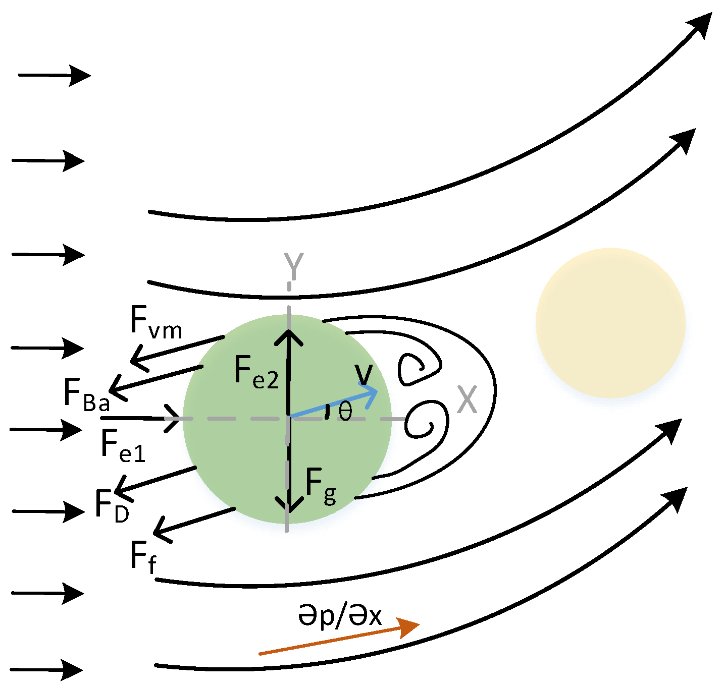
In the separation room, due to the action of compound electric field, the particle will be deflected when moving. The force patterns at different stages in the separation room are shown in Figure 4. We discuss the separation of the particles in the Cartesian coordinate system and establish the dynamic equations as follows:
{ m d v x d t = F e 1 F f cos θ F D cos θ F v m cos θ F B a cos θ m d v y d t = F e 2 F f sin θ F D sin θ F v m sin θ F B a sin θ F g .
During the movement of the particles, the particle diameter and velocity are small, most of the particles are in the Stokes region, and a few are in the Allen region, and there are no particles in the turbulent area. Therefore, only the Stokes and Allen areas are discussed here. The corresponding dynamic equations are expressed as:
( π 6 d p 3 ρ p + π 12 d p 3 ρ g ) x ¨ p + 3 π μ d p x ˙ p =   q 0 E 1   + ( π 6 d p 3 ρ p ρ g + 3 π 2 d p 2 ρ g μ v 0 C e C t e r f ( C t ) ) x p x p 2 + y p 2 ( π 6 d p 3 ρ p + π 12 d p 3 ρ g ) y ¨ p + 3 π μ d p y ˙ p =   q 0 E 2   + ( π 6 d p 3 ρ p ρ g + 3 π 2 d p 2 ρ g μ v 0 C e C t e r f ( C t ) ) y p x p 2 + y p 2 ,
( π 6 d p 3 ρ p + π 12 d p 3 ρ g ) x ¨ p + 3 π μ d p x ˙ p 1.4 =   q 0 E 1 + ( π 6 d p 3 ρ p ρ g + 3 π 2 d p 2 ρ g μ v 0 C e C t e r f ( C t ) ) x p x p 2 + y p 2 ( π 6 d p 3 ρ p + π 12 d p 3 ρ g ) y ¨ p + 3 π μ d p y ˙ p 1.4 =   q 0 E 2   + ( π 6 d p 3 ρ p ρ g + 3 π 2 d p 2 ρ g μ v 0 C e C t e r f ( C t ) ) y p x p 2 + y p 2 .

4. Results and Discussion

4.1. Dynamic Response of Different Electric Field Intensity in the Accelerating Region

In the previous sections, the dynamic equations were developed. The adaptive fourth-order Runge–Kutta approach [31] is utilized to solve the dynamic equations. After the particles are charged, they slowly enter the acceleration room, and the initial conditions of the acceleration room are determined. The particle enters the separation room after being accelerated by the electric field, and the initial conditions of the separation room are determined. The adaptive time step is adopted to ensure the correctness of the results. This paper takes the airflow at normal temperature and pressure as the research object. The body parameters and numerical simulation parameters are shown in Table 1.
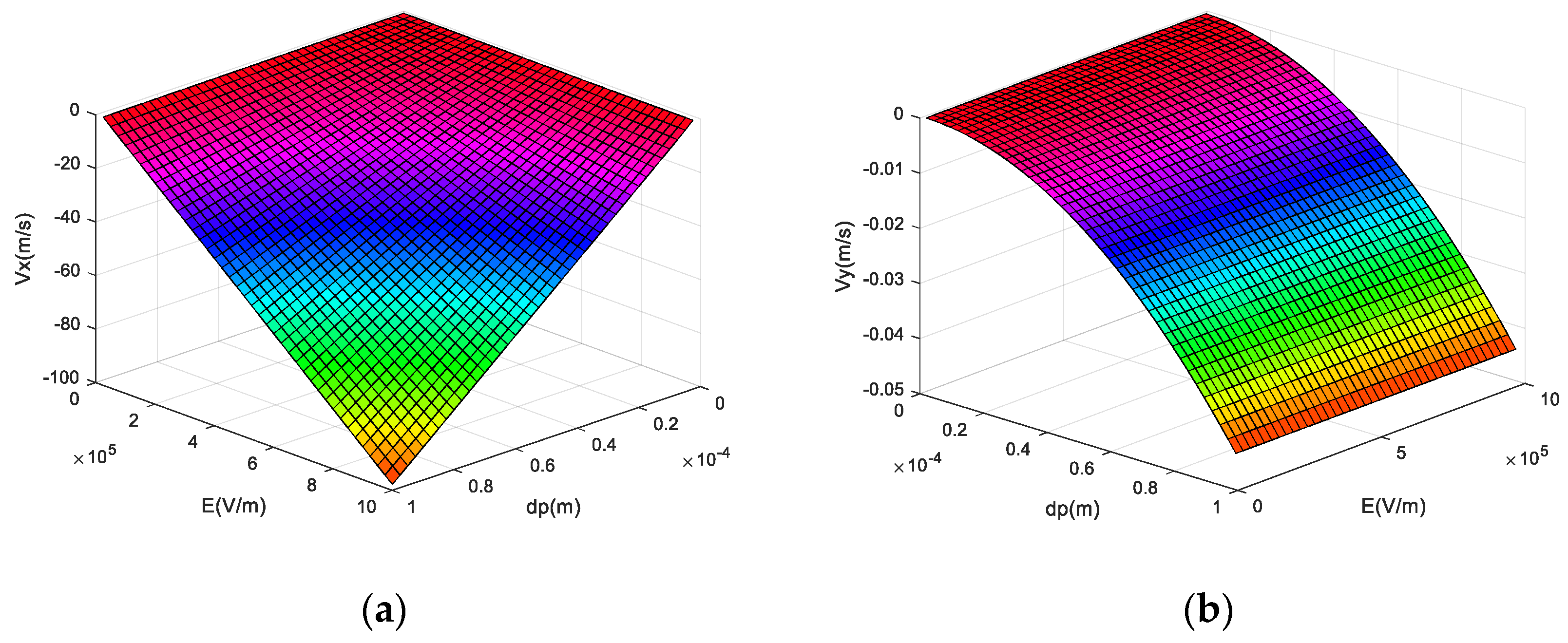
Figure 5 depicts the velocity response of the particle of different diameters at different electric field strengths. It can be seen that, the particle velocity increases with the increase of the particle diameter, and increases with the increase of electric field. Moreover, the electric field has a more significant effect on particles with large diameters. When the electric field is 30 kV, the speed of PM2.5 is −0.813 m/s, and the speed of PM10 is −2.754 m/s. They can pass through the acceleration area faster. In addition, the particle velocity increases with the increase of the particle diameter and increases with the increase of the electric field strength. When the electric field is 30 kV, the speed of PM2.5 is −3.59 × 10⁻⁵ m/s, and the speed of PM10 is −4.51 × 10⁻⁵ m/s. Comparing Figure 5a,b it can be seen that the speeds in the Y-axis direction and the X-axis direction differ greatly. The displacement of particles in the Y-axis direction is negligible.

4.2. Dynamic Response of Different Electric Field Intensity in the Separation Region

Figure 5 describes the velocity response of particles with different diameters under different electric field intensities. We chose a relatively easy to acquire voltage of 30 kV to accelerate the particles. After the acceleration of 30 kV voltage, the particle enters the separation room to determine the initial velocity of particle entering the separation room.
Figure 6 presents the displacement response of atmospheric particles with different diameters under different electric field intensities. As observed in Figure 6, in the ideal case, the displacement of the particles in the X direction increases with the increase of the particle diameter and increases with the increase of the transverse electric field. In the Y direction, the displacement exhibits different response laws. With the same vertical electric field, the Y direction displacement increases from negative displacement to positive displacement with the increase of particle size. It indicates that the separation effect is achieved for particles with different diameters. Without constraints, in the time of 2 s, PM100 will be displaced up to 2.35 m in the X direction and 0.94 m in the Y direction.
Figure 7 shows the change of atmospheric particle displacement with the electric field strength at normal temperature and pressure and electric field strength of 30 kV. In the X direction, with the increase of the electric field strength, the displacement of atmospheric particles continues to increase. As the diameter of the particles increases, the displacement increases continuously. The maximum X displacement can reach 0.875 m. In the Y-axis direction, the displacement increases as the electric field strength increases. When the diameter of atmospheric particulates is small, it presents a positive Y-axis displacement. As the diameter continues to increase, atmospheric particles begin to show a negative displacement in the Y direction. As the particle diameter increases, the negative displacement in the Y direction becomes larger. The displacement in the Y-axis direction gradually changes from a semi-parabolic descent to a complete parabolic shape as the diameter increases. The maximum displacement in the Y-axis direction is 0.2209 m.

4.3. Dynamic Response of Different Drag Force in the Separation Region

Figure 8 shows the displacement response of particles with different diameters after accelerating through the acceleration room under different drag forces, simulating a certain degree of vacuuming conditions. From Figure 8, the displacement of atmospheric particles in the X-axis direction increases as the drag coefficient decreases. The larger the particle diameter, the greater the displacement. The unit of resistance coefficient mu is N s/m2 by default. The inflection point of the resistance coefficient mu is 10−6. When the drag coefficient becomes smaller, the displacement of the particulate matter increases sharply, and the displacement changes quickly. In the Y direction, the displacement exhibits different response laws. When the vertical electric field is the same, as the particle size increases, the Y-direction displacement gradually increases from a negative displacement to a positive displacement. As the drag coefficient decreases, the particle displacement gradually increases. A positive displacement occurs when the particle diameter is small, and a negative displacement occurs when the particle diameter is large. The displacement gradually increases as the drag coefficient decreases. With the decrease of drag coefficient and the increase of particle diameter, the displacement of atmospheric particles gradually increased, and separation effect is achieved for particles with different diameters.
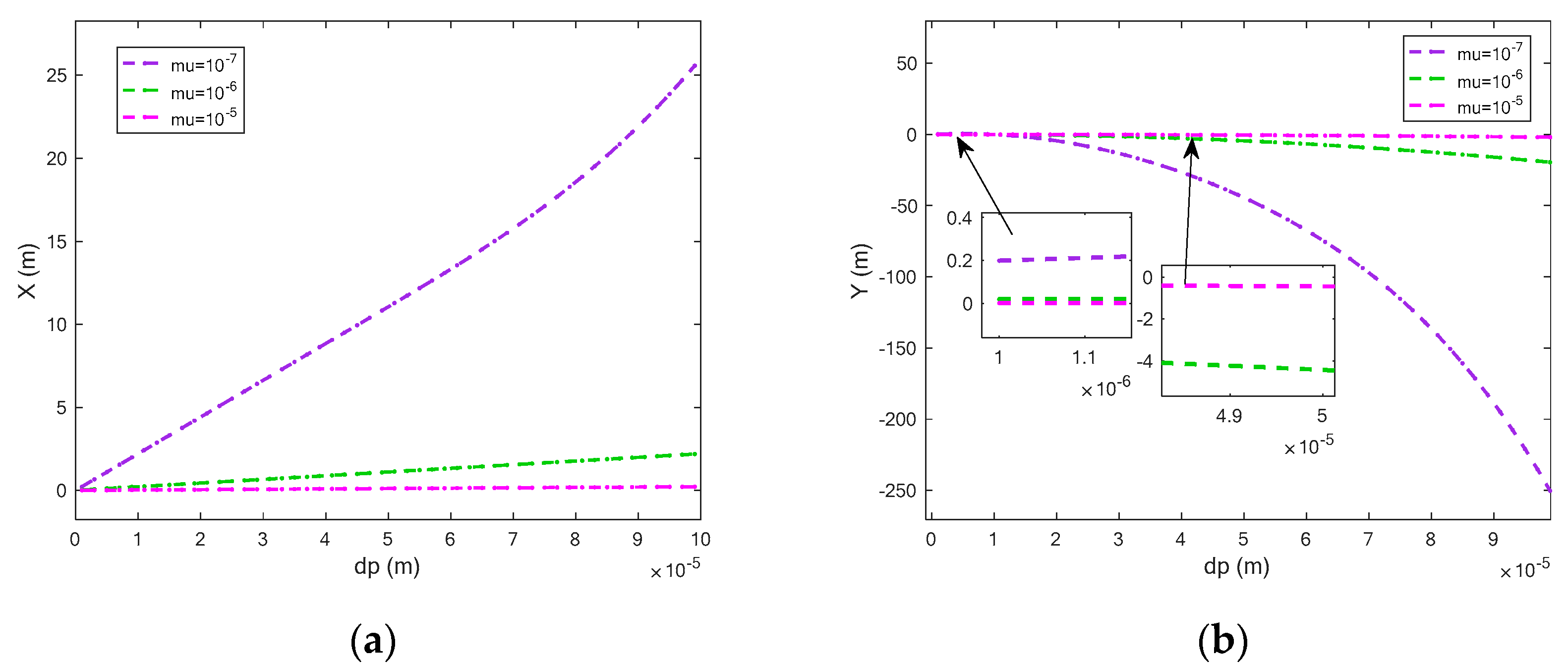
Figure 9 shows the variation of atmospheric particle displacement with drag coefficient when the electric field strength in the X and Y directions is 433 V. From Figure 9, in the X direction, as the drag coefficient decreases, the displacement of atmospheric particles decreases continuously. As the diameter of particles increases, the displacement increases continuously, and the drag coefficient has a greater influence on the displacement of particles. In ideal conditions without restriction, the X displacement can reach up to 25.57 m. Additionally, as the drag coefficient decreases, the particle displacement changes from a straight line to a curve. In the Y-axis direction, as the drag coefficient decreases, both the positive and negative displacements increase. When mu is 10−7, the effect of increasing displacement is obvious. To a certain extent, the phenomenon of separation between atmospheric particles is formed.
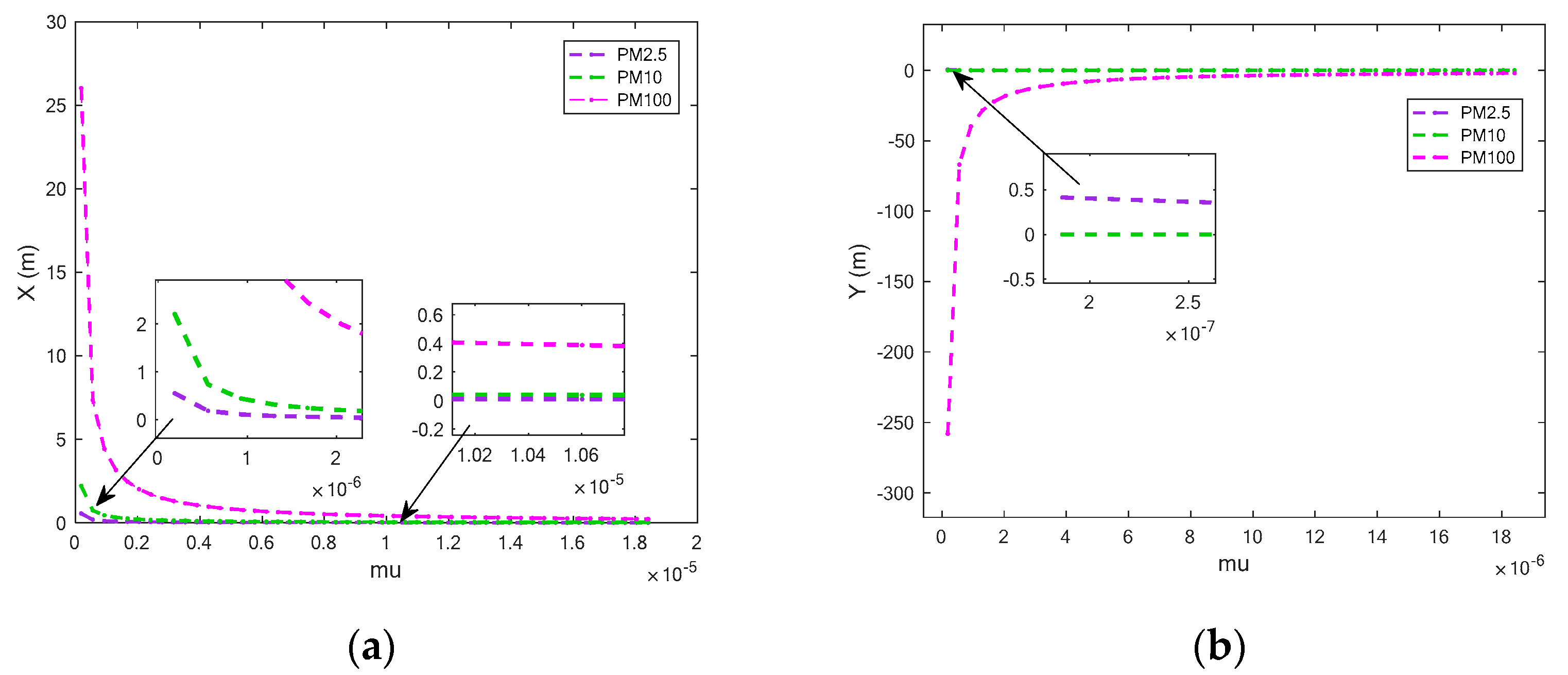
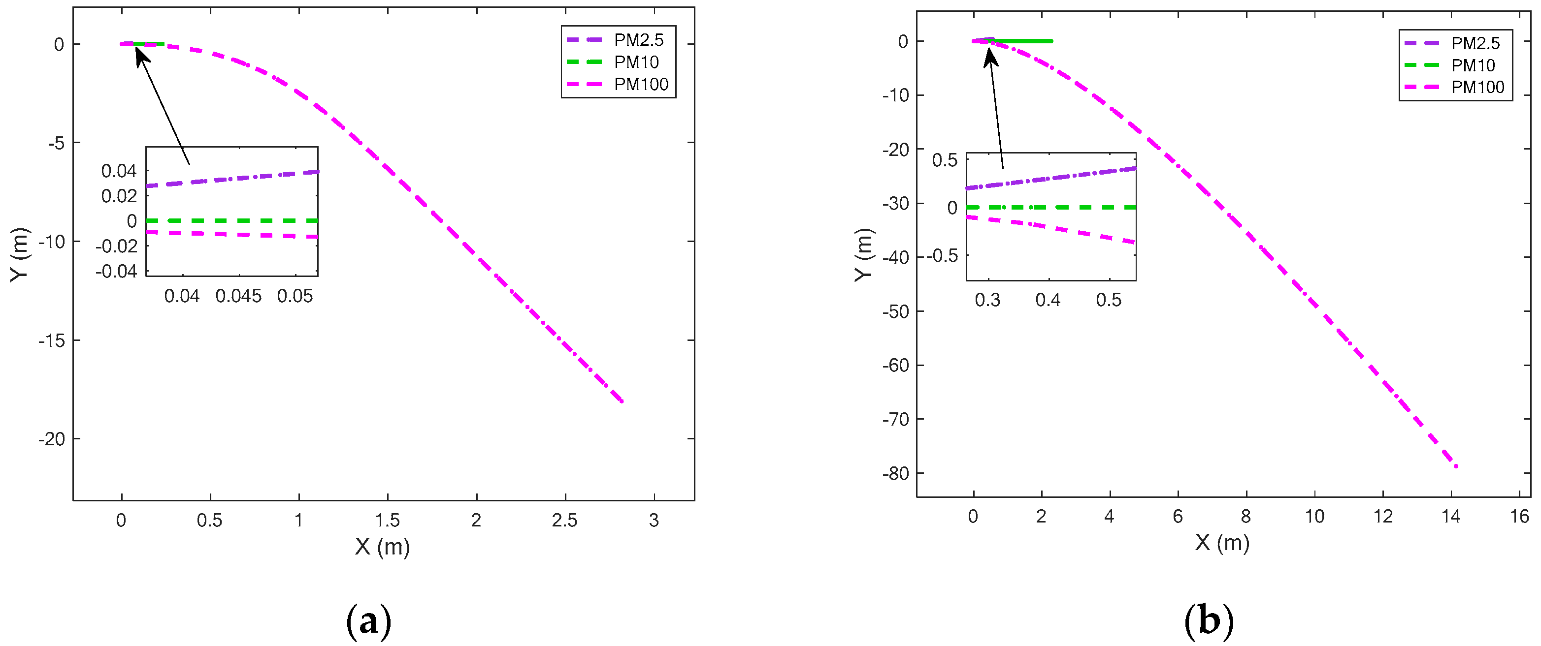
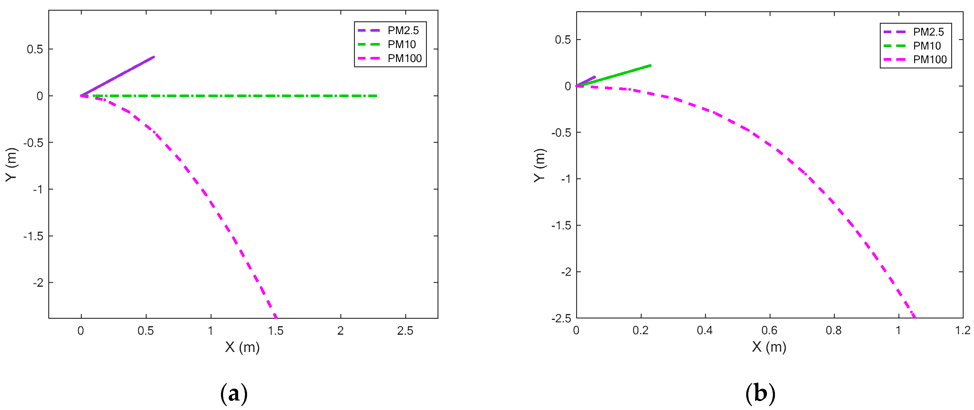
Figure 10 shows the effect diagram of atmospheric particulate separation under a different drag coefficient. From Figure 10a, when the drag coefficient decreases, the displacement of atmospheric particles in the x-axis direction increases. The mu is 10−6, which is the inflection point of the drag force coefficient. When the drag force coefficient changes again, the displacement of the particles increases sharply and changes rapidly. In the Y-axis direction, PM2.5 moves upward, and the displacement is small, the maximum is 0.45 m. PM10 maintains a small displacement, and the Y-axis displacement is small. PM100 moves downward, and when mu is less than 10−6, the displacement increases suddenly and drops sharply. Three kinds of particles are separated in space to achieve the particles separation purpose.
Figure 11 shows the analysis of the specific displacement changes of typical atmospheric particulate matter PM2.5, PM10, and PM100 under the same composite electric field and drag coefficient. Choosing the appropriate composite voltage, separation occurs between typical atmospheric particles. The larger the diameter of atmospheric particles, the greater the displacement of particles and the faster the separation speed. Particles with small diameters gradually separate out with time. Comparing Figure 11a,b, it can be seen that as the drag coefficient decreases, the displacement of atmospheric particulate matter increases significantly. The smaller the drag coefficient, the better the separation effect between atmospheric particles. The faster the particles with larger diameters are separated, the particles with smaller diameters will be separated slowly with the increase of time to achieve the purpose of separating atmospheric particles.

4.4. Dynamic Response of Electric Field and Drag Force in the Separation Region

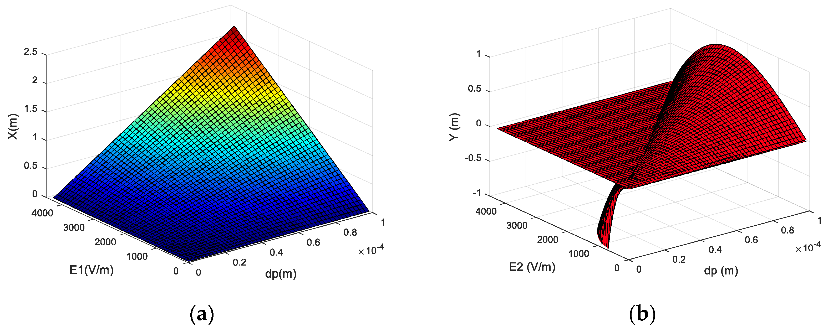
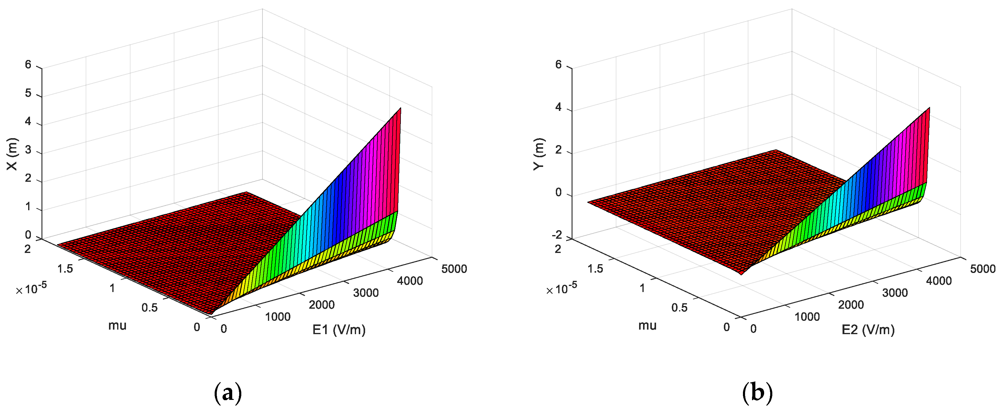
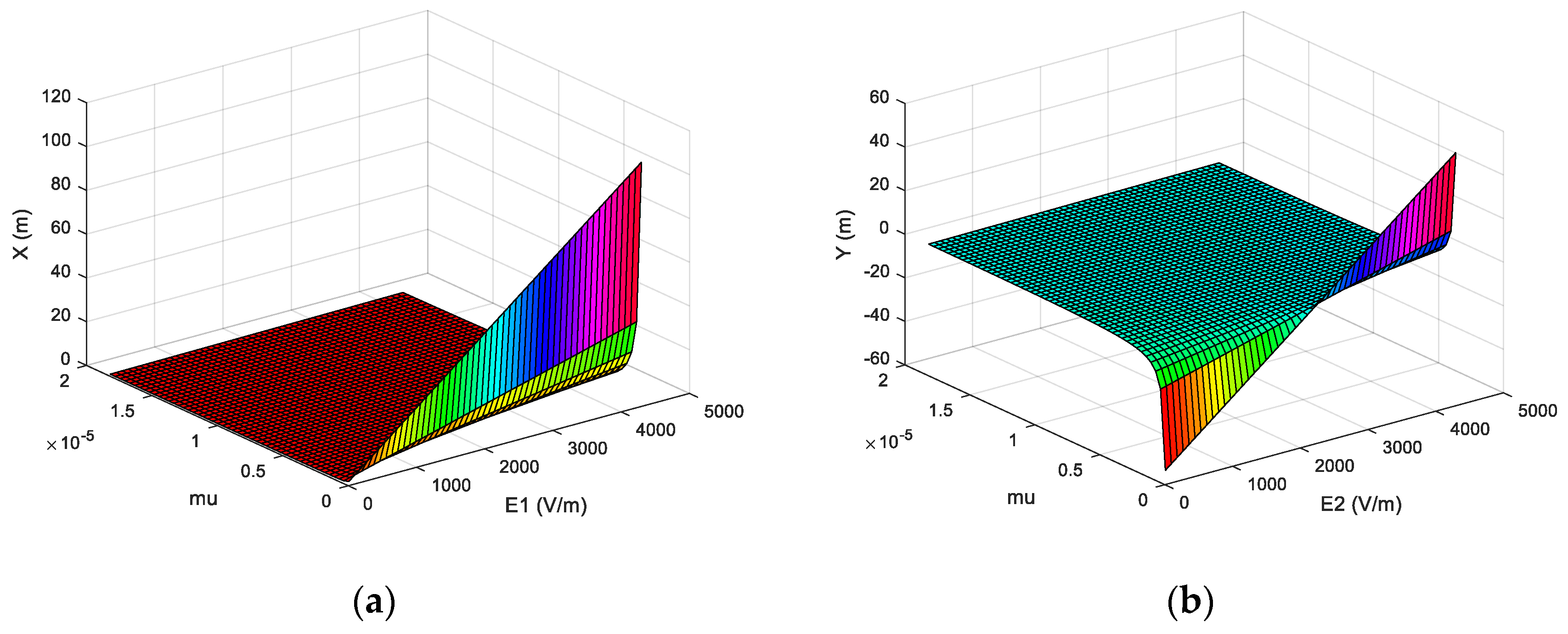
In order to further analyze the effect of separation between atmospheric PM under the combined action of electric field and drag force. The commonly used anode corona voltage E is 30 kV, and the acceleration voltage E is 30 kV in the acceleration room to accelerate atmospheric particulate matter. Figure 12 describes the displacement response of PM2.5 under different drag coefficients and electric fields. Figure 13 depicts the displacement response of PM50 under different drag coefficients and electric fields. It can be seen from Figure 12 and Figure 13 that in the ideal case, the displacement of particles in the X direction increases as the electric field strength E1 increases, and increases as the drag coefficient decreases. When the drag coefficient is small to a certain degree, the displacement of the particulate matter increases significantly. Then, as the diameter of atmospheric particles increases, the displacement in the X-axis direction also increases significantly. In the Y direction, the displacement exhibits different response laws. PM2.5 increases as the electric field strength E2 increases, and increases as the drag coefficient decreases. The displacement law of PM50 on the Y-axis is different. The PM50 displacement increases as the electric field strength E2 increases. Then, the displacement shape presents a “bow” that twists from negative displacement to positive displacement. In addition, when the drag coefficient is large, the shape is not obvious, and as the drag coefficient decreases, the shape becomes more prominent.
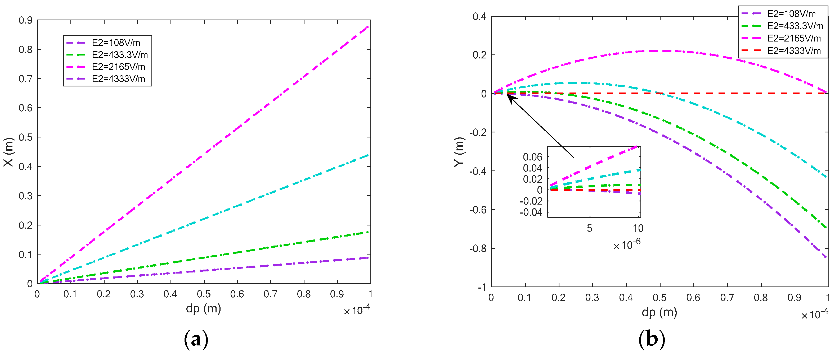
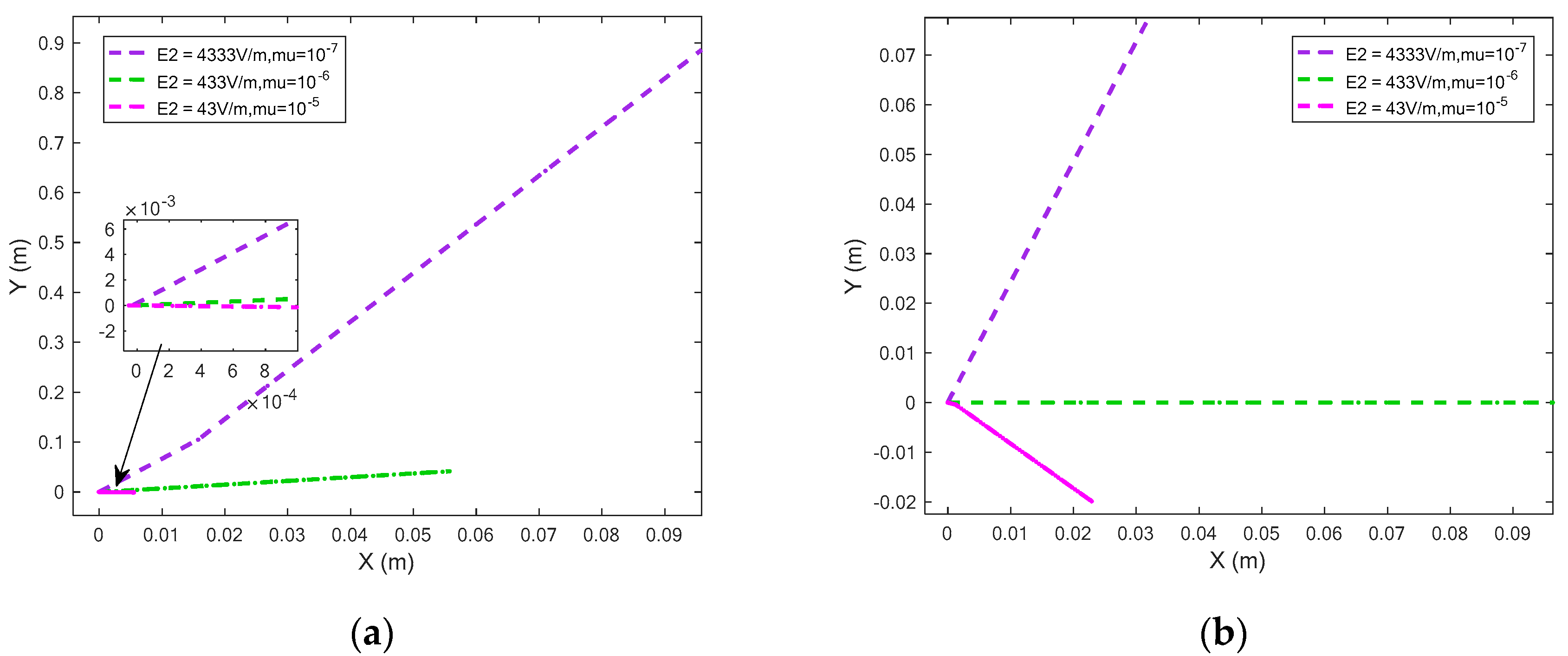
In order to deeply analyze the influence of the drag coefficient and electric field intensity on atmospheric particulate matter, we further study the influence of drag coefficient and electric field intensity on atmospheric particle displacement with particle diameter. Figure 14 shows the variation of the displacement of PM2.5 under different drag coefficients and electric field strength combinations. It can be seen from the figure that with the decrease of the electric field intensity E2, atmospheric particulate matter slowly changes from positive displacement to negative displacement, and the larger the particle diameter, the more obvious the effect. As the drag coefficient decreases, the displacement of atmospheric particles is greater in both the X and Y directions. Comparing (a) and (b) in Figure 14, when E2 is 433 V, PM2.5 moves upward, and PM10 basically keeps moving in the X direction. When the voltage rises, PM10 starts to move upward, and PM2.5 still moves upward. When the voltage drops to 43 V, PM2.5 basically has no longitudinal displacement, and PM10 moves downward. It can be seen that E2 is a suitable separation voltage of 433 V, and reducing the drag coefficient will improve the separation effect between atmospheric particles.
In order to further analyze the specific separation effect of atmospheric particles in space, under the same composite electric field and drag coefficient, the specific displacement changes of typical atmospheric particles PM2.5, PM10, and PM100 are analyzed. By comparing (a) and (b) in Figure 15, it can be seen that when E2 is 433 V, PM2.5 moves upward, PM10 maintains lateral displacement, and PM100 moves downward, which has an excellent separation effect, and subsequent easy collection of atmospheric particulate matter. When the voltage E2 is increased, PM10 starts to move upward, and there is also a certain displacement law. When the drag coefficient is 10−7, E1 is 433 V, and E2 is 433 V, the separation effect of atmospheric particles is more satisfactory. The smaller the drag coefficient, the better the separation effect of atmospheric particles.
According to the suggested method, a particle separator is simulated by commercial software and then a three-dimensional model is established. The separation system mainly includes three customized charging rooms, acceleration rooms, and separation rooms. They require machining accuracy to be less than 2.5 um. The separation system also includes blowers, high-voltage negative pulse power supplies, electronic balances, flow meters, etc. The preliminary estimate is estimated to cost $72,000. The separation system is simulated and analyzed according to actual materials. The aluminum parallel metal plate is used as the electrode plate and filled with air to simulate the real environment. Mesh electrodes are used in the separation room to control the size of the electric field. At the same time, atmospheric particles can move in three areas. In the simulated environment, the voltage E1 is set to 433 V, the voltage E2 is set to 433 V, the aerodynamic viscosity is 1.86 × 10⁻⁵ N s/m2, and the temperature is 298.15 K. Figure 16 shows the displacement changes of typical particulate matter PM2.5, PM10, and PM100. From Figure 16, PM100 moves in the negative direction of the X axis under the action of the electric field, PM10 keeps moving forward, and PM2.5 moves in the positive direction of the X axis. Comparing the displacement difference of numerical analysis, the maximum displacement difference of the three types of particles is 0.0017 m, which can be considered to be consistent.
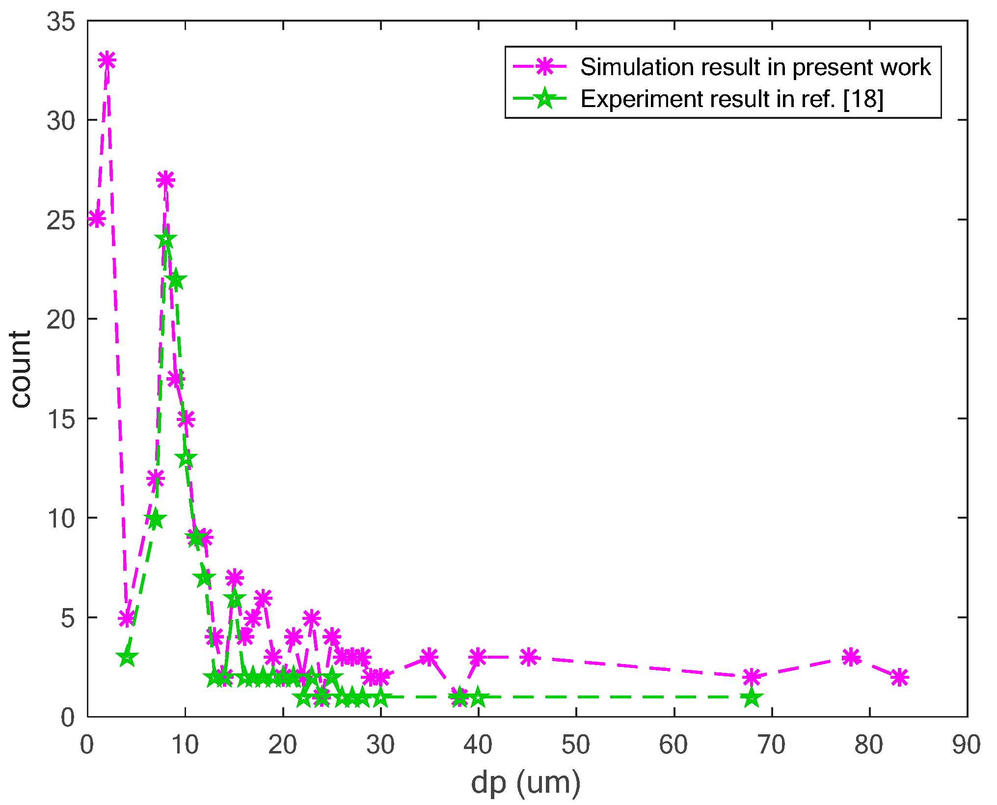
In order to further verify the method of this work, according to the data provided by Luca Lombardo [18], the same atmospheric particulate concentration is set in the simulation. The concentration of atmospheric particulate matter is shown in Table 2. Besides, the same volume of air is set to compare with the experimental data of Luca Lombardo to further verify the feasibility of our method. Figure 17 shows the comparison between the simulation analysis and the experimental data of ref. [18]. It can be seen that the results of this work are basically the same with that of ref. [18], which verifies the reliability and effectiveness of the proposed method.

5. Conclusions

In this work, the dynamic response and separation effect of multi-factor separation of atmospheric particulate matter based on the composite electric field are investigated. A dynamic model for the separation of atmospheric particulate matter considering the effect of a composite electric field was established. In the dynamic model, the changes of the electric field force, basset force, additional mass force, and air resistance are taken into consideration. Through the numerical solution of the model, the dynamic response of the separation of atmospheric particles based on the composite electric field is discussed. Through these responses, in order to separate particles more accurately, it is a feasible separation method to reduce the drag coefficient and control the electric field strength. Compared with other methods, the method proposed in this work is easy to operate and has little environmental requirements. The valuable phenomena obtained are as follows:
  • In the acceleration room, the velocity of atmospheric particles increases with the increase in particle diameter, and increases with the increase in electric field strength. Particles can pass through the acceleration room faster. The displacement of the particles in the Y-axis direction is negligible and does not affect the subsequent separation movement.
  • In the separation room, when the composite electric field changes, the displacement of particles in the Y-axis direction gradually increases from a negative displacement to a positive displacement as the electric field strength increases, which provides the basics of the separation. When the drag coefficient changes, there will be a sudden increase in displacement.
  • When the drag coefficient and the combined electric field work together, as the particle diameter increases, the Y-direction displacement assumes a “bow” shape that twists from negative to positive displacement. As the drag coefficient decreases, the shape becomes more prominent. The electric field strength affects the separation direction of the particles.

Author Contributions

Conceptualization, M.W. and S.L.; Data curation Y.W. and H.Z.; Funding acquisition, J.Z.; Methodology, M.W.; Project administration, S.L.; Software, M.W.; Validation, S.L.; Writing—original draft, M.W.; Writing—review & editing, Y.W., H.Z. and S.L. All authors have read and agreed to the published version of the manuscript.

Funding

This work was supported in part by the National Natural Science Foundation of China under Grant 11802168, Grant 61603238, and Grant 51575331, in part by project funded by China Postdoctoral Science Foundation (No. 2019M661458), and in part by Science and technology projects in Henan province of China.

Acknowledgments

The authors would like to thank the anonymous reviewers for their constructive and helpful comments.

Conflicts of Interest

The authors declare that there is no conflict of interest regarding the publication of this paper.

References

  1. Jacobson, M.C.; Hansson, H.-C.; Noone, K.J.; Charlson, R.J. Organic atmospheric aerosols: Review and state of the science. Rev. Geophys. 2000, 38, 267–294. [Google Scholar] [CrossRef] [Green Version]
  2. Esworthy, R. Air Quality: EPA’s 2013 Changes to the Particulate Matter (PM) Standard; Congressional Research Service Reports: Washington, DC, USA, 2015. [Google Scholar]
  3. Chiang, C.-T. Design of a High-Sensitivity Ambient Particulate Matter 2.5 Particle Detector for Personal Exposure Monitoring Devices. IEEE Sens. J. 2017, 18, 165–169. [Google Scholar] [CrossRef]
  4. Marinov, M.B.; Hensel, S.; Ganev, B.; Nikolov, G. Performance evaluation of low-cost particulate matter sensors. In Proceedings of the 26th International Science Conference Electronics (ET), Sozopol, Bulgaria, 12–15 September 2017; pp. 1–4. [Google Scholar]
  5. Kim, K.-H.; Kabir, E.; Kabir, S. A review on the human health impact of airborne particulate matter. Environ. Int. 2015, 74, 136–143. [Google Scholar] [CrossRef] [PubMed]
  6. Meo, S.A.; Memon, A.N.; Sheikh, S.A.; Rouq, F.A.; Usmani, A.M.; Hassan, A.; Arian, S.A. Effect of environmental air pollution on type 2 diabetes mellitus. Eur. Rev. Med. Pharmacol. Sci. 2015, 19, 123–128. [Google Scholar] [PubMed]
  7. Basu, R.; Harris, M.; Sie, L.; Malig, B.; Broadwin, R.; Green, R. Effects of fine particulate matter and its constituents on low birth weight among full-term infants in California. Environ. Res. 2014, 128, 42–51. [Google Scholar] [CrossRef] [PubMed]
  8. Buggiano, V.; Petrillo, E.; Allo, M.; Lafaille, C.; Redal, M.A.; Alghamdi, M.A.; Khoder, M.; Shamy, M.; Muñoz, M.J.; Kornblihtt, A.R. Effects of airborne particulate matter on alternative pre-mRNA splicing in colon cancer cells. Environ. Res. 2015, 140, 185–190. [Google Scholar] [CrossRef] [PubMed]
  9. World Health Organization. Quantifying Environmental Health Impacts. Available online: http://www.who.int/quantifying_ehimpacts/news_events/en/ (accessed on 14 November 2017).
  10. AirNow. Available online: https://airnow.gov (accessed on 20 December 2016).
  11. Air Quality Data—Central Pollution Control Board. Available online: http://cpcb.nic.in/RealTimeAirQualityData.php (accessed on 20 December 2016).
  12. Air Pollution—European Environment Agency. Available online: https://www.eea.europa.eu/themes/air/intro (accessed on 20 December 2016).
  13. Symonds, J.P.; Reavell, K.S.J.; Olfert, J.S.; Campbell, B.W.; Swift, S.J. Diesel soot mass calculation in real-time with a differential mobility spectrometer. J. Aerosol Sci. 2007, 38, 52–68. [Google Scholar] [CrossRef]
  14. Wang, J.; Storey, J.; Domingo, N.; Huff, S.; Thomas, J.; West, B. Studies of Diesel Engine Particle Emissions During Transient Operations Using an Engine Exhaust Particle Sizer. Aerosol Sci. Technol. 2006, 40, 1002–1015. [Google Scholar] [CrossRef]
  15. Schrobenhauser, R.; Strzoda, R.; Fleischer, M.; Hartmann, A.; Amann, M.-C. Detection of the mass of fine particulate matter using light scattering and inertial filtering in a miniaturized sensor setup. Meas. Sci. Technol. 2014, 25, 035103. [Google Scholar] [CrossRef]
  16. Dong, M.; Iervolino, E.; Santagata, F.; Zhang, G.; Zhang, G. Integrated Virtual Impactor Enabled PM2.5Sensor. IEEE Sens. J. 2017, 17, 2814–2821. [Google Scholar] [CrossRef]
  17. Manikonda, A.; Zikova, N.; Hopke, P.K.; Ferro, A.R. Laboratory assessment of low-cost PM monitors. J. Aerosol Sci. 2016, 102, 29–40. [Google Scholar] [CrossRef]
  18. Lombardo, L.; Parvis, M.; Angelini, E.; Grassini, S. An Optical Sampling System for Distributed Atmospheric Particulate Matter. IEEE Trans. Instrum. Meas. 2019, 68, 2396–2403. [Google Scholar] [CrossRef]
  19. Liu, B.; Chen, X.; Cai, H.; Ali, M.M.; Tian, X.; Tao, L.; Yang, Y.; Ren, T.; Bo, L.; Xiao, C.; et al. Surface acoustic wave devices for sensor applications. J. Semicond. 2016, 37, 21001. [Google Scholar] [CrossRef]
  20. Wasisto, H.S.; Merzsch, S.; Waag, A.; Uhde, E.; Salthammer, T.; Peiner, E. Airborne engineered nanoparticle mass sensor based on a silicon resonant cantilever. Sens. Actuators B Chem. 2013, 180, 77–89. [Google Scholar] [CrossRef]
  21. Wasisto, H.S.; Merzsch, S.; Waag, A.; Uhde, E.; Salthammer, T.; Peiner, E. Portable cantilever-based airborne nanoparticle detector. Sens. Actuators B Chem. 2013, 187, 118–127. [Google Scholar] [CrossRef]
  22. Mariani, L.; Pastore, F.; Pezze, M. Dynamic analysis for diagnosing integration faults. IEEE Trans. Softw. Eng. 2011, 37, 486–508. [Google Scholar] [CrossRef]
  23. Wei, Y.; Liu, S. Numerical analysis of the dynamic behavior of a rotor-bearing-brush seal system with bristle interference. J. Mech. Sci. Technol. 2019, 33, 3895–3903. [Google Scholar] [CrossRef]
  24. Mehdizadeh, E.; Kumar, V.; Wilson, J.C.; Pourkamali, S. Inertial Impaction on MEMS Balance Chips for Real-Time Air Quality Monitoring. IEEE Sens. J. 2017, 17, 2329–2337. [Google Scholar] [CrossRef]
  25. Jiang, F.; Liu, S.; Xin, S.; Zhang, H. Electromagnetic Nondestructive Testing Model and Surface Magnetic Field Analysis for Circumferential Cracks on Metal Rod. J. Nondestruct. Eval. Diagn. Progn. Eng. Syst. 2019, 2, 1–17. [Google Scholar] [CrossRef]
  26. Kim, Y.H.; Maeng, J.-Y.; Park, D.; Jung, I.-H.; Hwang, J.; Kim, Y.-J. Micromachined cascade virtual impactor with a flow rate distributor for wide range airborne particle classification. Appl. Phys. Lett. 2007, 91, 43512. [Google Scholar] [CrossRef]
  27. Chen, L.-J.; Ho, Y.-H.; Hsieh, H.H.; Huang, S.-T.; Lee, H.-C.; Mahajan, S. ADF: An Anomaly Detection Framework for Large-Scale PM2.5 Sensing Systems. IEEE Internet Things J. 2017, 5, 559–570. [Google Scholar] [CrossRef]
  28. Wang, Y.; Wang, Y.; Chen, D.; Liu, X.; Wu, C.; Xie, J. A Miniature System for Separation and Detection of PM Based on 3-D Printed Virtual Impactor and QCM Sensor. IEEE Sens. J. 2018, 18, 6130–6137. [Google Scholar] [CrossRef]
  29. Zhang, Y.; Chang, Y.; Lv, G.; Ma, W.; He, Y.; Xie, G. Separation of Silicon from Coarse Al-Si Melts under Alternating Electromagnetic Field with Varying Frequencies. Silicon 2020. [Google Scholar] [CrossRef]
  30. Guo, K.; Lv, Y.; He, L.; Luo, X.; Zhao, J. Experimental study on the effect of spatial distribution and action order of electric field and magnetic field on oil-water separation. Chem. Eng. Process. Process Intensif. 2019, 145, 107658. [Google Scholar] [CrossRef]
  31. White, H.J. Industrial Electrostatic Precipitation; Addison-Wesley: Reading, MA, USA, 1963; pp. 21–56. [Google Scholar]
  32. Davies, C.N. Definitive equations for the fluid resistance of spheres. Proc. Phys. Soc. 1945, 57, 259–270. [Google Scholar] [CrossRef]
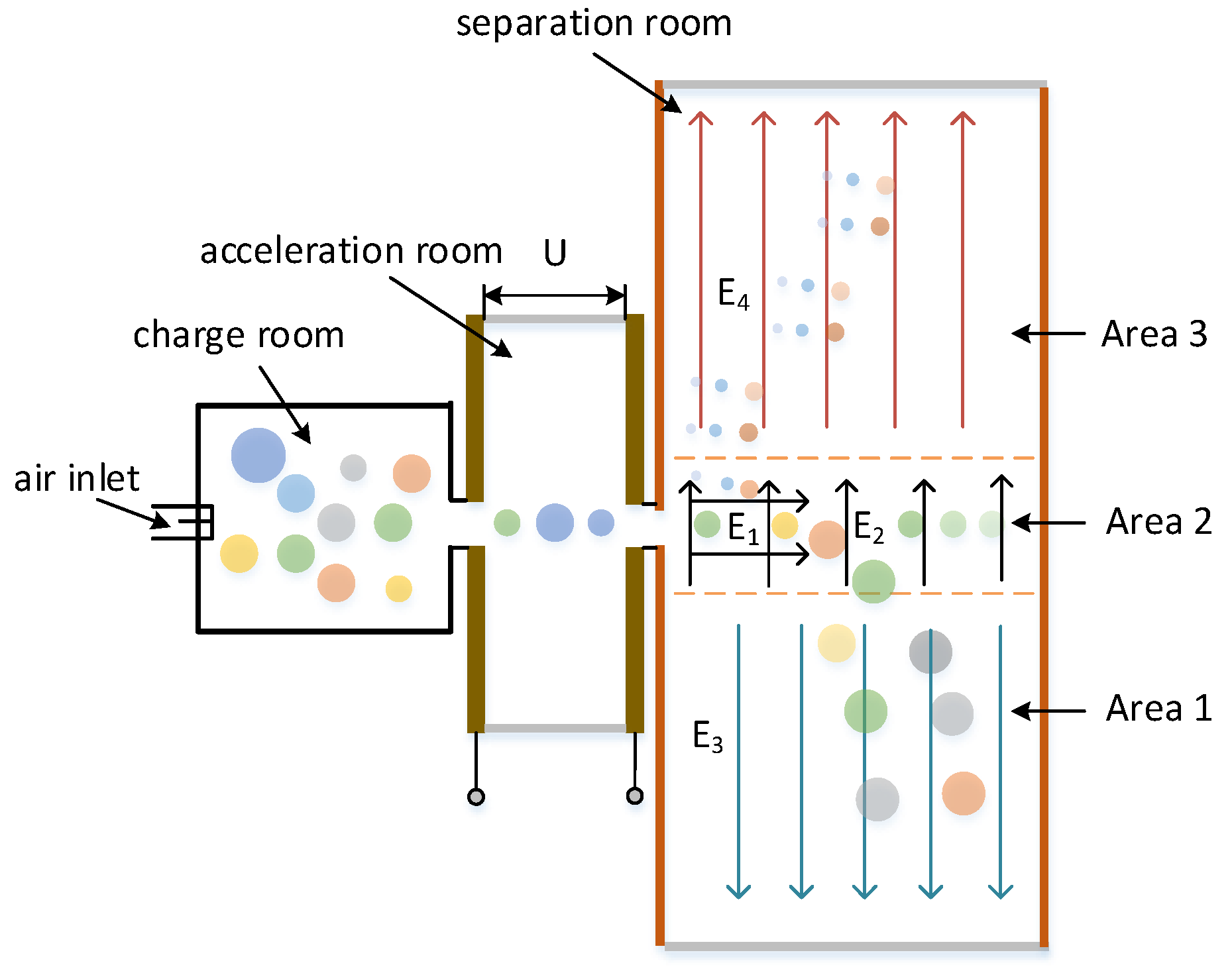
Figure 1. Proposition of composition and principle of atmospheric particulate separation matter based on the compound electric field.
Applsci 10 05999 g001
Figure 2. Simplified scheme of composition and principle of charged room.
Applsci 10 05999 g002
Figure 3. Particles force in accelerating electric field.
Applsci 10 05999 g003
Figure 4. Particles in the electromagnetic separation zone.
Applsci 10 05999 g004
Figure 5. Dynamic velocity response of different electric field strengths and different particle diameters: (a) X-axis velocity response; and (b) Y-axis velocity response.
Applsci 10 05999 g005
Figure 6. Dynamic displacement response of different electric field strengths and different particle diameters: (a) X-axis displacement response; and (b) Y-axis displacement response.
Applsci 10 05999 g006
Figure 7. Particle diameter and displacement response: (a) X-axis displacement response; (b) Y-axis displacement response.
Applsci 10 05999 g007
Figure 8. Dynamic displacement response of horizontal electric field strength and particle diameter: (a) X-axis displacement response; (b) Y-axis displacement response.
Applsci 10 05999 g008
Figure 9. Particle diameter and displacement response for the same drag coefficient: (a) X-axis displacement response; (b) Y-axis displacement response.
Applsci 10 05999 g009
Figure 10. Variation of the drag coefficient of particle separation displacement: (a) Displacement in the X direction; (b) displacement in the Y direction.
Applsci 10 05999 g010
Figure 11. Effect diagram of atmospheric particulate separation under different drag coefficient: (a) mu = 10−6; (b) mu = 10−7.
Applsci 10 05999 g011
Figure 12. Dynamic displacement response of PM2.5 under the combined action of drag force and electric field: (a) X-axis displacement; (b) Y-axis displacement.
Applsci 10 05999 g012
Figure 13. Dynamic displacement response of PM50 under the combined action of drag and electric field: (a) X-axis displacement; (b) Y-axis displacement.
Applsci 10 05999 g013
Figure 14. Displacement response of atmospheric particles with different diameters under drag and electric field: (a) PM2.5; (b) PM10.
Applsci 10 05999 g014
Figure 15. Under the same drag force and electric field, the separation effect of PM2.5, PM10, and PM100: (a) E2 = 433 V, mu = 10−7; (b) E2 = 866 V, mu = 10−6.
Applsci 10 05999 g015
Figure 16. Simulation effect of separation of atmospheric particles: (a) PM100; (b) PM10; (c) PM2.5.
Applsci 10 05999 g016
Figure 17. Comparison of the particle size distribution of simulated atmospheric particulate matter with experiment result in ref. [18].
Applsci 10 05999 g017
Table 1. Particle separation parameter.
ParametersSize
vacuum dielectric constant ε 0 = 8.875 × 10 12 F/m
unit chargeqε = 1.6 × 10⁻¹⁹ C
Boltzmann constantk = 1.38 × 10⁻²³ J/K
absolute temperatureT = 298.15 K
relative dielectric constantε = 5
air densityρg = 1.1691 kg/m3
particle densityρp = 1.5 × 10³ kg/m3
dynamic viscosityμ = 1.86 × 10⁻⁵ N·s/m2
the initial velocityV0 = 0.001 m/s
Table 2. Atmospheric particulate matter concentration.
PM100-10PM10PM2.5PM1PM10-2.5
8.02 μg/m34.98 μg/m34.83 μg/m34.25 μg/m30.15 μg/m3