Abstract
This study focuses on the structural analysis of the front single-sided swingarm of a new three-wheel electric motorcycle, recently designed to meet the challenges of the vehicle electrification era. The primary target is to develop a swingarm capable of withstanding the forces applied during motorcycle’s operation and, at the same time, to be as lightweight as possible. Different scenarios of force loadings are considered and emphasis is given to braking forces in emergency braking conditions where higher loads are applied to the front wheels of the vehicle. A dedicated Computer Aided Engineering (CAE) software is used for the structural evaluation of different swingarm designs, through a series of finite element analysis simulations. A topology optimization procedure is also implemented to assist the redesign effort and reduce the weight of the final design. Simulation results in the worst-case loading conditions, indicate strongly that the proposed structure is effective and promising for actual prototyping. A direct comparison of results for the initial and final swingarm design revealed that a 23.2% weight reduction was achieved.
1. Introduction
Motorcycle technology advancements have been evident throughout the years, following or even exceeding the trends of automotive technologies. Accordingly, electric motorcycles are becoming a reality and they already have an important market share (over 30% in 2019) [1]. Several technology breakthroughs have been introduced up to now, providing numerous production vehicles and stimulating a huge effort towards their research and development by motorcycle manufacturers and startups. Electric motors, batteries and powertrains, are the key factors mainly researched by the industry. But electrification of powertrains also enables the redesign of several critical motorcycle parts.
One critical structural part of all motorcycles is the front suspension system that connects the chassis with the front wheel. Several alternative concepts of front suspension can be found, such as girder forks, leading link and hub center steering [2], introducing various advantages in motorcycle handling. The majority of the production motorcycles globally install telescopic forks, as front suspension systems, even though this entails specific disadvantages [3]. As the choice of the suspension system has major effects on the performance and handling of the motorcycle, alternative front suspension systems have been researched and have also been installed on production motorcycles [2,4]. Another issue of motorcycle design is the use of two or three wheels and specifically the setup of two wheels front and one rear. These kind of motorcycles can be considered as trikes or motorcycles, depending on the way they tilt as well as the lateral distance between the front wheels. Trikes are a different vehicle category, due to different handling and cornering. It is clear that up to now, two-wheel motorcycles dominate the market. However, in the last years different three-wheel concept vehicles have been introduced (Honda Neowing, Tokyo, Japan, Kawasaki J, Tokyo, Japan), production models are already on the road (Yamaha NIKEN, Shizuoka, Japan), and motorcycle magazine reviews have highlighted the advantages of two front wheels for handling, braking and safety feeling of the riders [5]. Linked to the above facts, extensive research on three-wheel motorcycles and their front suspension systems design, is needed and should be carefully evaluated. On this track, our research team have been focusing on the design and development of a new three-wheel electric motorcycle [6], with an innovative two-wheel front system arrangement using a single-sided swingarm for each front wheel and hub center steering. This motorcycle was developed to meet the challenges of future electric vehicles’ and the development of the two-wheel front system arrangement was customized for installation on the specific vehicle. It must be noted, that the replacement of a gasoline engine by an electric powertrain in the same space, provides additional freedom in chassis design of future electric motorcycles, which makes it easier to install such an alternative front system. The work presented here is mainly focused on the structural analysis of the swingarm, which is a critical component of the front system.
Research on three-wheel motorcycles reported in the literature is limited. Related studies are mainly focused on dynamic modelling and stability analysis of these vehicles [7,8]. Simple and advanced dynamic models of three-wheel motorcycles are developed and specific modes of operation (capsize, weave and wobble) are recognized and evaluated compared to two-wheel vehicles through simulation. Other researchers are focused on the effects of passing over low friction coefficient surfaces, where the riders of three-wheel vehicles have indicated that one noteworthy characteristic is the vehicle’s stability when cornering, over a low friction surface, like slippery or wet road. As indicated, under these conditions the decrease in lateral force on one front tire, passing over the low friction road surface, is compensated by the other front tire [9].
As mentioned, swingarm structural behavior is the main topic covered in this research. Based on related literature there are several publications focused on swingarm structural analysis, but they all explore single-sided [10,11,12,13,14] or double-sided [15,16,17] rear swingarms. Double-sided swingarms hold the rear wheel by both sides of its axle, while single-sided ones are a type of swingarm which lies along only one side of the rear wheel and hold it in one side, allowing it to be mounted like a car wheel. In all cases, a static analysis is considered, presenting stress and displacements based on different loading conditions. Focusing on the single-sided swingarms, in [10] the loads applied correspond to maximum traction and lateral bending forces, comparing an aluminum and Carbon Fiber Reinforced Plastic (CFRP) version. A multi objective optimization is performed for the redesign of the carbon fiber version targeting maximum stiffness and minimum weight. Bedeschi [14] presented a similar analysis, towards weight optimization, considering CFRP material. Smith [11,13] also used a static analysis based on torsional and vertical loads, trying to achieve higher torsional stiffness and minimum weight. Considering double-sided swingarms, a relative procedure is followed where structural analysis is based on braking and cornering [15], torsional loads [16], or extreme loading such as performing a wheelie [17]. Regarding material use, the majority is focused on aluminum alloys such as 7075-T6 [15], CFRP [18] and comparisons of aluminum and steel versions [16,17]. Based on the aforementioned literature, other valuable information was also gathered (Table 1), including: a) weight of swingarms developed, b) vehicle motor power and c) safety factor. It is evident that rear swingarm’s weight depends on the motor power used on the motorcycle, as well as if it is single or double-sided. In Table 1, double- or single-sided swingarms are defined as (D) or (S), respectively. For motor power less than 40 KW, only double-sided can be found and their weight is 2.6–2.7 kg for aluminum and CFRP versions, respectively. On powertrains ranging between 130 and 185 KW, single-sided swingarms weight is 4.1–4.2 kg for CFRP and 5 kg for aluminum, while double-sided swingarms are 5.3–6.85 kg for different aluminum versions. The safety factor targeted by most researchers, even though data are limited, has values close to N = 2.

Table 1.
Rear swingarm specifications in the literature.
Braking and cornering forces are accounted for in most of the literature for rear swingarms. The magnitude of these forces is related to tire-ground friction and a simplification called “friction circle or ellipse” can be used to understand the maximum forces available for braking and cornering [2]. It assumes that the maximum tire friction force possible in any direction is a constant, which means that a tire can support a specific maximum force either for cornering, or braking, or any combination of steering and braking forces that result to the same maximum resultant force available, which is a simplification of reality. Other research findings exist, where more accurate tire models for combined braking and steering force components can be found, such as the Pajecka Magic formula [19] and BNP-MNC [20]. But according to the above and considering that, in our case, we are exploring the use of a front swingarm, the maximum loading scenario can be defined under emergency braking conditions in a longitudinal driving direction.
Basic theory of braking forces calculation can be found in various publications, including related books [21,22,23], as well as research focused on evaluation of the effects of braking loads applied on single-sided swingarms [12]. It must be noted though, that when brake forces are calculated, motorcycle tires and especially tire coefficient of friction are important as detailed in Section 2.3. Another important factor, directly linked to braking conditions, is the effect of deceleration. Braking deceleration of motorcycles is differentiated according to vehicle brake design and driver’s ability to avoid skidding during braking [21]. Experimental brake tests have been conducted by different research teams measuring deceleration values, revealing the effect of the driver but also the differences that occur by using front, rear or both brakes simultaneously [24,25,26]. This part is exclusively presented in the following sections of this work, highlighting the importance of deceleration on braking calculations, in order to adequately define the loads applied on a swingarm.
To the best of our knowledge, there is no other analysis of a front single-sided swingarm in the relevant literature, as the majority of research is related to rear swingarms. Comparing the loads applied on a front or rear swingarm, several differences exist, such as: (a) the effect of torque during acceleration, which is not considered on a front swingarm, (b) motorcycle weight distribution loads, as also (c) higher braking forces applied on the front wheels. It can be easily understood, that weight and stiffness of rear swingarms cannot be directly compared to those of a front swingarm. Hence, the main contribution of this work is to present valuable results and insights, regarding stress and displacements calculated for the front single-sided swingarm design proposed. To cope with the forces applied during vehicle operation and at the same time to be lightweight, different designs are evaluated under different loading scenarios. Since braking conditions correspond to a major factor of forces applied, this is the worst-case loading scenario considered. For the evaluation procedure, a dedicated CAE (ANSA, Beta CAE Systems, Thessaloniki, Greece) software is used for a series of finite element analysis simulations. Based on preliminary results obtained, the redesign of the swingarm is discussed, targeting higher structural effectiveness and lower weight. For this purpose, a topology optimization procedure is carried out to assist and shape the new design. Finally, an evaluation of different swingarm versions under specific loading conditions is discussed, considering simulation results of stresses and displacements, which depend on design modifications.
2. Calculation of Forces on a Motorcycle
For the definition of the loadcases used in the simulations, the weight distribution and brake forces acting on the front swingarm must be calculated. In this section, a brief analysis of the relevant theory and experimental results found in the literature is presented.
2.1. Weight Distribution
Assuming a simple motorcycle model, the basic loads acting from weight distribution and braking can be determined as shown in Figure 1, where the motorcycle and the rider are modeled as a single rigid body. Supposing a flat road and ignoring the contribution from rolling resistance and aerodynamic forces, the loads on the vehicle’s wheels are then calculated as shown below [21].
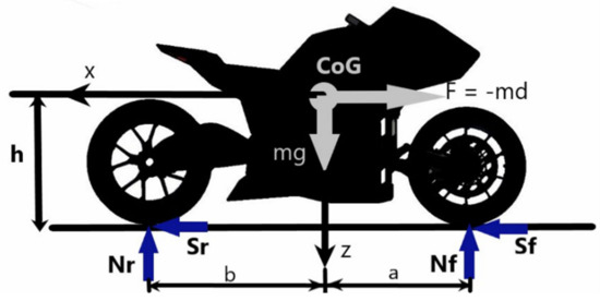
Figure 1.
Simple motorcycle model of acting forces during braking.
In Figure 1, a represents the distance of front wheel from Center of Gravity (CoG), b is the distance of rear wheel from CoG and h measures the height of the CoG. Applying the sum of forces with respect to axes X and Z and sum of torques at the center of gravity, we obtain the following equations:
where, Sf is the front braking force, Sr is the rear braking force, Nf is the reaction from the ground to the front wheel, Nr the reaction from the ground to the rear wheel, d represents the deceleration, m the total mass and m × d the inertial force from the deceleration.
Rewriting the Equations (1)–(3) with respect to Nf and Nr, results in:
Using the above equations, the weight distribution resulting in the loads acting on the front and rear wheels can be obtained.
2.2. Braking Forces and Tire Friction
As found in Equation (1), the total braking force (Stot) is:
A condition that should be avoided to maintain driver safety during braking is tire skidding, resulting in a loss of tire grip with the road [21]. Tire traction limit D is based on tire characteristics and is related to the ratio μ, which is the friction force (or otherwise the normalized braking force), effected by the braking force S and the vertical load N. In order to maintain road grip during braking, this ratio should not exceed a maximum available value of D, for the front (Df) and rear (Dr) tire traction, respectively:
As the total brake force (Stot) increases, tire skidding may occur either in the front or in the rear tire depending on braking force distribution [21]. In order to examine this phenomenon, the ratio of braking balance (ρ) is introduced, linking the braking force on the rear wheel and the total braking force:
By using Equations (1)–(3) and (7)–(9), normalized braking force μ may be expressed as a function of the deceleration d and the braking balance ρ, as follows [21]:
When ρ = 0 then μr = 0 meaning only the front brakes are applied, while if ρ = 1 just the rear brakes are applied.
In order to calculate the brake ratio at the verge of skidding, the actual deceleration at this point must be known [22]. Assuming the tires (front and rear) have the same coefficient of friction, the total braking force at the point of skidding is calculated by Equation (2):
By equating (6) with (12), the expression for maximum deceleration is obtained:
The negative sign is an indication that the vehicle is in a state of deceleration.
In general, tire friction data are linked to road conditions (dry, wet, ice), as also on different road material types (such as asphalt, gravel etc.) [7,9,27]. Nevertheless, motorcycle tires are different than car tires and have different shapes of contact patch on the road [27,28]. Experimental results focused on motorcycle tire friction coefficient (μ) calculation, indicate values close to μ = 0.8 [22]. Experimental and theoretical results for car tires in contact with a road made from tarmac in dry conditions can be found in [23,27], presenting a range of values 0.7 < μ < 1.0. Research on motorcycle tires can also be found [22,27], indicating that for a dry road μ = 0.8. Considering all the above information, for our calculations the reference coefficient of friction used for the front and rear tires is μf = μr = 0.8. Therefore, based on Equation (13) and assuming μ = 0.8 as a reference value, the maximum theoretical deceleration so that no tire skidding occurs is calculated at d = 0.8 g.
2.3. Urgent Braking in Real Conditions
The way motorcycle drivers use brakes in emergency situations affects motorcycle response and differentiates deceleration magnitude. For this purpose, several experimental tests have been conducted by different researchers, using professional or ordinary drivers, different sport or sport-touring motorcycle models and different braking conditions (using front, rear or both brakes) [24,29,30,31,32,33,34,35,36]. Relevant experiments on low-power motorcycles (100–150 cc) were conducted in [26], as well as in wet road conditions where decelerations are lower [25]. These tests reveal the range of decelerations achieved in reality (minimum–maximum) and can be compared to theory. A summary of these results is presented in Table 2 and at the last row the mean value for all minimum and all maximum decelerations is calculated. In this calculation, we have not accounted for the tests conducted in [26] due to the low power of motorcycles used in the tests. Also all values included are without the use of an anti-lock braking system (ABS).
Table 2.
Braking deceleration rates in g reported in the literature (dry and wet road).
Combined braking (front and rear brake use) is considered as the best way to brake in an emergency situation and this is represented in the results, where the maximum deceleration achieved is 0.96 g. Lower values are found for rear brake use (0.46 g), considered as the worst choice. Finally, using only front brakes results in maximum decelerations up to 0.89 g. It can be seen that the range of decelerations vary from test to test. For this reason, a mean value of all maximum and all minimum decelerations is calculated in the last row of Table 2 and is considered as a more adequate magnitude of reference. Based on that, when only front brakes are applied, the mean value of maximum deceleration is d = 0.75 g.
Comparing this experimental reference value (0.75 g) with the theoretical value of deceleration (d = 0.8 g) calculated in the previous Section 2.2, we observe that theoretical calculations are 5.8% higher than the experimental. Due to the small difference, we choose the worst case (theoretical deceleration value d = 0.8 g), as the reference value used for the maximum braking forces applied in calculations hereafter.
3. Testbed Vehicle Specifications and Loading Scenarios
The proposed swingarm design is installed on the front suspension system of a three-wheel electric motorcycle (Daedalus). Using two wheels at front, two identical single-sided swingarms are used to hold the wheels. The top and side view of this assembly is shown in Figure 2a,b, respectively. In order to calculate the forces acting on the testbed vehicle, the technical specifications and corresponding dimensions of CoG related to Figure 1 are presented in Table 3.
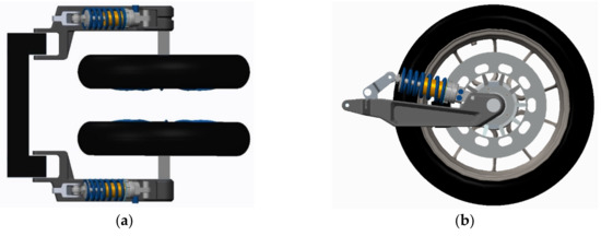
Figure 2.
Front swingarm assembly: (a) top view; (b) side view.
Table 3.
Testbed vehicle (Daedalus) technical specifications.
3.1. Front Swingarm Design and Materials
The initial design of the single-sided swingarm is presented in Figure 3, while the assembly of related components that are included in the simulation, is shown in Figure 4. As shown, at the back side the swingarm is connected to the chassis through an axle inserted in the spacers, while on the front it is connected to the wheel through the swingarm axle. The front axle is attached on the swingarm with two bearings and its other side is connected to the wheel using a hub center steering system.
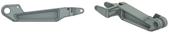
Figure 3.
Front swingarm initial design.
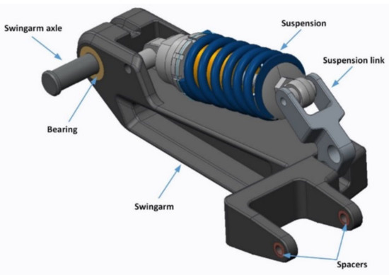
Figure 4.
Front swingarm and related components assembly.
3.2. Weight Distribution Forces—First Loading Scenario
As explained in Section 2.1, the weight distribution forces on the wheels are determined by the position of the center of gravity (CoG) and the mass of the motorcycle including the driver, in our case 340 kg. By subtracting the unsprung mass of the wheels (21 kg), the total mass acting on the CoG is m = 319 kg. Weight distribution on the front and rear wheels is calculated using Equations (4) and (5), assuming deceleration d = 0, resulting in Nf = 1572.9 N and Nr = 1555.9 N. Force Nf is distributed equally on the front two wheels, resulting in Nfleft = Nfright = 786.45 N. These forces correspond to the first loading scenario considered in the simulations.
3.3. Braking Forces—Second Loading Scenario
Using Equation (4) force Nf can be calculated for different deceleration values (d). In addition, using Equation (10), the coefficient of friction (μf) can be obtained, related to different braking distribution factors (ρ) and decelerations. The brake force acting on the front wheels (Sf) is then calculated based on Nf and μf. The same procedure is used to calculate the rear braking force Sr. The worst-case scenario of forces applied is considered when only the front brake is used (ρ = 0). Assuming a friction factor μf = 0.8 and a maximum deceleration of d = 0.8g, results in Sfleft = Sfright = Sf/2 = 1251.75 N on each front wheel. The brake moment (Mbr) generated by Sf, considering the front tire radius (R = 0.32 m), is Μbr = Sf × R = 400.5 Nm. The vertical load is also found equal to Nfleft = Nfright = 1210 N. These forces correspond to the second loading scenario considered in the simulations. Using Equation (13), the maximum deceleration that can be achieved in order to avoid tire skidding would be d = 0.8 g, assuming μ = 0.8.
4. Modelling and Simulation
Finite elements modelling requires specific steps, depending on the pre-processor used, in order to prepare a CAD part for Finite Elements Analysis (FEA) simulation. This includes modelling of forces, constraints, connections of parts in the assembly, material specification and mesh generation. All these steps are detailed in the following paragraphs. A dedicated CAE software (ANSA, Beta CAE Systems, Thessaloniki, Greece) is used for this purpose [37], providing adequate results.
4.1. Geometry Mesh and Materials
The ANSA pre-processor is used for the development of the geometry mesh and volume elements are used for higher results accuracy (Figure 5). The mesh of the swingarm has 97,259 volume elements, from which 87,475 are Tetras and 9784 are Pyramids elements. The total mesh of all the components included in the swingarm assembly has 116,818 volume elements (Figure 6).
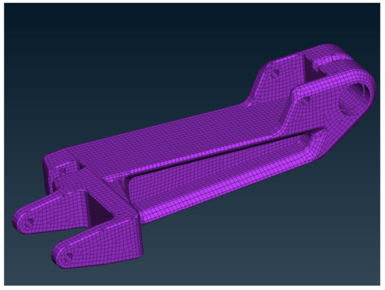
Figure 5.
Mesh of the initial swingarm design.
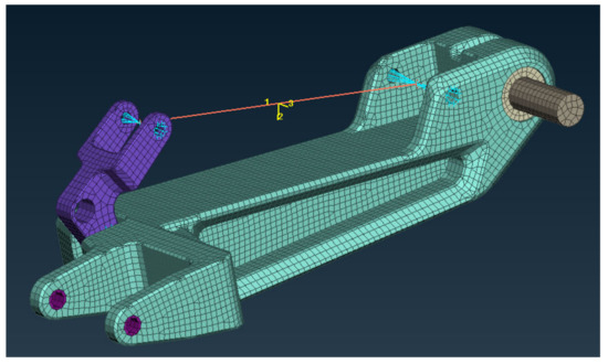
Figure 6.
Mesh of components assembly for the swingarm design.
The modelling of material properties used for the preliminary simulations can be found in Table 4, where the required properties used by the pre-processor are: (a) Elastic modulus, (b) Poisson ratio, (c) Shear modulus, (d) Density and (e) Yield strength. The materials initially considered are: (a) aluminum 7075-T6 for the swingarm and the suspension link, (b) stainless steel AISI-304 for the swingarm axle and the bearings, (c) steel AISI-130 for the suspension, all modelled as isotropic materials. Suspension has been simplified to a steel round beam (shown with a line in Figure 6) in order to reduce mesh elements number and is assumed to be a rigid component.
Table 4.
Materials properties used in preliminary simulations.
4.2. Connections and Contacts
The connection of different components in the assembly is defined using bolts, related to suspension and suspension link, or contact functions for spacers and bearings. Figure 7a presents bolts connections placement and Figure 7b depicts the contact connections as modelled on the assembly.
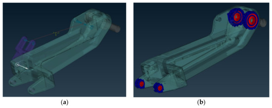
Figure 7.
Connections modeled: (a) with bolts; (b) with contacts.
4.3. Forces and Constraints
Constraints are modelled as shown in Figure 8a, placed as fixtures on the rear part of the swingarm connected to the chassis. Suspension movement is also fixed using a constraint on the suspension link. The forces are applied considering the calculated values of the vertical force Nf (first loading scenario) and a clockwise moment Mbr (used with Nf for second loading scenario) placed on the end of the swingarm axle (Figure 8b).
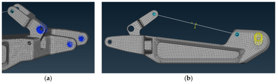
Figure 8.
Finite element analysis model: (a) constraints; (b) loads.
The assumption that suspension is rigid and that no tire modelling is considered, is a simplification used to reduce computational time under the static analysis presented here. Stress and displacements calculated in this way are expected to be higher than in the case when the suspension was operating normally and tires could also compensate part of the loads. These assumptions help us on evaluating different swingarm designs, which is the main target here, but in order to obtain more precise results and achieve higher weight reduction, these modelling procedures should be applied.
4.4. Topology Optimization
A general optimization problem is identified firstly as a problem of finding the optimal topology and then as a problem of finding the optimal shape or finding the optimal cross sections [38]. Topology optimization is a mathematical process that aims to find the optimal distribution of the material of a construction, while satisfying its support conditions and loads. It is implemented by combining finite elements for analysis and mathematical programming techniques for solving [38,39]. ANSA’s SOL200 was used to conduct topology optimization simulations in the present work [37]. The first important parameter defined is the design area, corresponding to the area of the part where the problem of topology optimization will be solved, while areas not included in the solution are called non-design areas [38]. In our case, the design area is the swingarm excluding the rear brackets connected to the chassis. The second parameter is the definition of the objective function and constraints. The objective function for this application corresponds to the minimization of the weighted deformation energy (min compliance). Using this objective function, the residual mass percentage and the static loading scenario are taken as constraints. The first restriction refers to the percentage of mass removed from the original mass of the swingarm.
5. Results
The linear static analysis of the front swingarm is based on the previously mentioned modelling of forces, materials, connections and constraints and the solver calculates the stresses (Von Misses) and the displacements. Two loading scenarios are conducted and discussed related to the forces applied. The first scenario includes the weight distribution of the forces (weight) resembling a vertical bending scenario, while the second investigates the effect of maximum braking forces. For the representation of the results, META post-processor was used. The first part of results shows the initial swingarm design under the two loading scenarios (Section 5.1 and Section 5.2). In Section 5.3, details of the redesign process towards the final swingarm design are presented, based on topology optimization results and alternative designs evaluation. Finally, in Section 5.4 simulation results of the final swingarm design are shown and a detailed comparison to the initial design is discussed.
5.1. Initial Swingarm Design—First Loading Scenario
In this part, the force applied is Nf = 786.45 N, which corresponds to weight distribution on the front wheel (Section 3.2). Stress results and related displacements for the swingarm are shown in Figure 9.
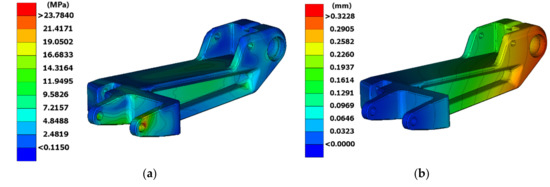
Figure 9.
Stress (a) and displacement (b) results in 1st loading scenario.
A normal stress distribution is observed on the swingarm, where a maximum stress of 23.78 MPa occurs on one of the constrained points that connects it to the chassis. This result has a low magnitude that needs no further evaluation. The displacement results show a maximum value of 0.32 mm for the swingarm.
5.2. Initial Swingarm Design—Second Loading Scenario
Considering the case of braking, the forces applied are calculated in Section 3.3. As mentioned, the highest braking forces occur at deceleration of d = 0.8 g when using only the front brakes. According to this, the forces applied in the simulation are Nf = 1210 Ν and Mbr = 400.5 Νm. The results of stresses and displacements obtained are presented in Figure 10.
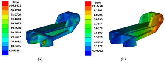
Figure 10.
Stress (a) and displacement (b) results in 2nd loading scenario.
The maximum stress is 98.6 MPa placed on the right rear bracket, far lower than the material yield stress (503 MPa), corresponding to a safety factor N = 5.1. This yields that excess of material should be removed. Another important observation is that on the rest of the part stresses distribution are less than 60 MPa, while displacement results show a maximum value of 1.27 mm. According to these insights, certain modifications can be made on swingarm design in order to reduce weight. Additionally, a change of material could be recommended in order to cut down raw material and production costs.
5.3. Final Swingarm Design
Considering the forces applied on the different loading scenarios, we mostly depend on results obtained for the worst-case scenario which is under emergency braking conditions. A swingarm redesign and material replacement is decided, targeting lower weight and production cost. It is clear that stress and displacements will be raised, but the objective is a safety factor close to N = 2 and at the same time to keep displacements as low as possible. A topology optimization procedure was used at first, so as to assist on redesign of the swingarm and obtain valuable results regarding specific areas of material removal (Figure 11). Modelling and simulation were conducted based on parameters referred in Section 4.4. The finite element model was solved using the second (worst) loadcase scenario for various topology optimization parameters and the new form obtained was again validated (solved) in a static analysis. In this way it was possible to fine tune certain parameters such as the percentage of mass removed from the swingarm, which was finally set to 40% reduction compared to the original mass. It must be noted that we also experimented with higher reduction percentages, but the results indicated: a) even more complex swingarm forms, which were difficult to manufacture with our production capabilities (CNC machining) and b) similar stresses and displacements. For these reasons, the specific percentage of mass reduction (40%) was chosen. As seen in Figure 11, material was mostly removed on the front part of the swingarm as well as in the middle, indicating that hollow parts should exist at these points. Most of the features of the form obtained through this procedure were incorporated in the new design.
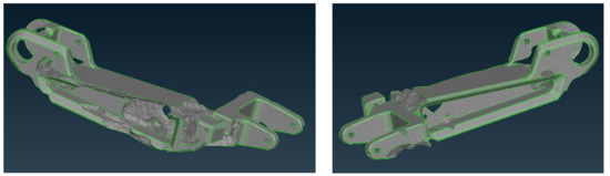
Figure 11.
Topology optimization results for the swingarm.
Various designs were considered and evaluated and two new alternatives are shown in Figure 12a,b. Their analysis was based on loads of the first loading scenario and the material used was aluminum 7075-T6. The results obtained are presented in Figure 12c,d, respectively.
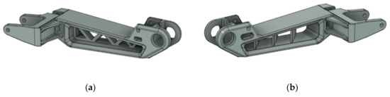
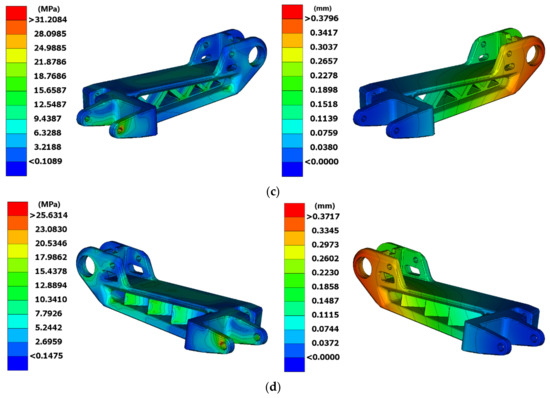
Figure 12.
Different swingarm versions and results: (a) 1st alternative swingarm design; (b) 2nd alternative swingarm design; (c) results of stresses and displacements for 1st alternative swingarm; (d) results of stresses and displacements for 2nd alternative swingarm.
The first alternative design showed a weight reduction of 13% (4.94 kg), while the second alternative provided even higher weight reduction of 18.5% (4.62 kg). Considering the results of analysis, the first one presented higher maximum stress (37.2 MPa—first, 25.63 MPa—second) while both had almost the same displacements (0.38 mm—first, 0.37 mm—second). It is evident that the second design alternative was the type of design we should focus on for the final version. The final form was slightly changed, mostly affected by our production capabilities, where CNC machining manufacturing was chosen. According to the redesign procedure followed, the final swingarm design is presented in Figure 13.

Figure 13.
The final redesigned single-sided front swingarm.
As mentioned, low stress distribution and a high safety factor of the initial design gave us the flexibility to choose a new aluminum alloy (5083-H116) for the swingarm, targeting lower production cost. The modelling of the isotropic material properties used for the new swingarm assembly can be found in Table 5. Four different materials are used: (a) Aluminum 5083-H116 (swingarm and link), (b) Stainless steel 304 (suspension), (c) Stainless steel SS-A4-80 (swingarm axle), (d) Steel AISI4130 (bearings). The required properties used by the pre-processor are: (a) Elastic modulus, (b) Poisson ratio, (c) Shear modulus, (d) Density and (e) Yield strength.
Table 5.
Materials properties used in the final modelling.
5.4. Final Swingarm Design Results
An identical modelling process is followed for the new materials applied, as in the initial design. Only the worst-case scenario (second loading scenario) is used for the evaluation and comparison to the initial version. The forces applied are again Nf = 1210 Ν and Mbr = 400.5 Νm and the results of stresses and displacements are presented in Figure 14.
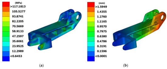
Figure 14.
Stress (a) and displacement (b) results in 2nd loading scenario for the final swingarm design.
The maximum stress calculated on the swingarm has a magnitude of 117.2 MPa, resulting in a safety factor N = 1.95 (yield strength is 228 MPa). As expected, maximum stress is once more observed on one of the constrained points that connects the swingarm to the chassis, as was the case in the simulation results of the first design. It must be also noted that stress distribution on the rest of the swingarm is below 70 MPa. The maximum displacement results in a value of 1.59 mm. Even though there are no comparative results for front swingarms on the literature, these displacements under heavy braking conditions are evaluated as acceptable. That means that no driving or handling problems would be noticed by the driver in braking conditions. A comparison of results from the simulations conducted for the initial and final swingarm design, can be found in Table 6, including maximum stresses, displacements, weight and safety factor.
Table 6.
Results comparison of the initial and final swingarm design.
As shown, the maximum stresses are 19% higher in the final design, as also displacements are raised by 25%. These results were expected but at the same time do not raise any concerns, since they are lower than the material yield strength. Safety factor is reduced, which is normal for this kind of structure and ensures structural rigidity safety levels. The main target was of course to lower weight, which is accomplished, considering that a 23.2% reduction was achieved. Finally, the change of materials decided had minimum overall effects on our results, but on the other hand will help the most on reducing production costs.
The development procedure presented and decisions taken towards the final design, were based on finite element analysis simulations that were modeled based on our knowledge and experience. Due to the lack of relevant research on front single-sided swingarms, no real comparison can be made to similar research or tests in order to validate our results. One engineering parameter found from rear swingarm analysis (as referred to in Table 2 and used for validation in our case), is the safety factor. In rear swingarms it ranges from 1.53 to 2.39 with a mean value of 1.95, which is an important parameter that we successfully met on our new design. The next step would be to set up an experimental testing procedure on a custom test rig, which would provide additional strain and displacement data for the validation and tuning of our finite element model. We should also mention that since the suspension and tire effects are not considered in our model, the results of stresses and displacements are higher, providing additional certainty that we can further reduce the weight. According to the above, we are confident that the proposed design will provide the needed safety during driving and braking.
6. Discussion
The work presented is focused on the design and development of a front single-sided swingarm used on a new three-wheel electric motorcycle. To the best of our knowledge there is no literature for front single-sided swingarm analysis, since most of the research found is related to rear swingarms. Comparing a front and a rear swingarm, loading conditions are differentiated. One difference is the effect of loads from the motor through the chain on a rear swingarm and on the other hand higher braking forces applied on the front wheel of a motorcycle.
The main targets set for the development of this part, are structural safety and low weight. A dedicated CAE software was used for the modelling of loads, constraints and materials applied, in order to evaluate a front swingarm design through series of finite element analysis simulations. Results of stresses and displacements were calculated and presented. A review of braking conditions was also presented, in order to identify the braking forces applied and investigate their effects on the structural strength of the part under consideration. In the simulations conducted, two loading scenarios were performed. The first scenario included weight distribution forces, while the second scenario investigated the effect of braking forces, considered as the worst-case scenario. At first, an initial swingarm design was evaluated. In the worst-case scenario, the maximum stress calculated was 98.6 MPa, far lower than the yield stress (503 MPa), corresponding to a safety factor of N = 5.1. Displacement results showed a maximum value of 1.27 mm on this design. A swingarm redesign and material replacement was decided, targeting lower weight and production cost. A topology optimization procedure was used, so as to assist the redesign of the swingarm and obtain valuable results regarding specific areas of material removal. The final form was also affected considering our production capabilities, targeting manufacturing with CNC machining. In the final swingarm design, exactly the same modelling process was followed and only the worst-case scenario (second loading scenario—braking) was used in the simulations. A direct comparison of results for the initial and final swingarm design revealed that, the maximum stresses are 19% higher in the final design (117.2 MPa), as well as displacements were raised by 25% (1.59 mm). Safety factor was reduced to N = 1.95, which is normal for these type of structures (as related to rear swingarm literature) and ensures structural rigidity. The main target was of course to lower weight, which is accomplished since a 23.2% reduction was achieved, resulting in a weight of 4.35 kg.
The main contribution of this work was to present valuable results and insights, based on finite element analysis simulations, revealing stress and displacements that are calculated for various versions of a new front single-sided swingarm design. The results presented indicate strongly that the proposed structure is effective and promising for actual prototyping. For a future work, the modelling of suspension and tires could be applied, in order to obtain more refined results and target further weight optimization.
Author Contributions
Conceptualization, P.S.; Methodology, P.S. and E.C.; Software, E.C.; Validation, P.S. and N.C.T.; Formal Analysis, N.C.T.; Writing—Original Draft Preparation, P.S. and E.C.; Writing—Review and Editing, P.S., E.C. and N.C.T.; Visualization, E.C. and P.S.; Supervision, N.C.T. All authors have read and agreed to the published version of the manuscript.
Funding
This work has been partially funded by the TUC’s internal project ”TUC Eco Racing team”.
Acknowledgments
The authors would like to acknowledge the DEADALUS/TUC team’s members who contributed and helped in the development.
Conflicts of Interest
The authors declare no conflict of interest.
References
- Electric Motorcycles & Scooters Market Size by Product (Motorcycles, Scooters), by Battery (SLA, Li-ion), by Voltage (24V, 36V, 48V) Industry Analysis Report, Regional Outlook, Growth Potential, Price Trends, Competitive Market Share & Forecast, 2020–2026. Available online: https://www.gminsights.com/industry-analysis/electric-motorcycles-and-scooters-market (accessed on 20 July 2020).
- Foale, T. Motorcycle Handling and Chassis Design: The Art and Science, 1st ed.; Tony Foale: Madrid, Spain, 2002. [Google Scholar]
- Cossalter, V. Motorcycle Dynamics, 2nd ed.; Vittore Cossalter: Padova, Italy, 2006. [Google Scholar]
- Mavroudakis, B.; Eberhard, P. Analysis of Alternative Front Suspension Systems for Motorcycles. Veh. Syst. Dyn. 2006, 44, 679–689. [Google Scholar] [CrossRef]
- Cycle World. Available online: https://www.cycleworld.com/2019-yamaha-niken-gt-first-ride/ (accessed on 12 July 2020).
- Deadalus Site. Available online: www.daedalus.tuc.gr (accessed on 27 July 2020).
- Sponziello, A.; Frendo, F.; Guiggiani, M. Stability analysis of a three-wheeled motorcycle. SAE Int. J. Eng. 2009, 1, 1396–1401. [Google Scholar] [CrossRef]
- Bartaloni, F. Multibody Analysis of a New Three Wheeled Vehicle. Ph.D. Thesis, University of Pisa, Pisa, Italy, 14 April 2008. [Google Scholar]
- Terada, K.; Sano, T.; Watanabe, K.; Kaieda, T.; Takano, K. Investigation of the behavior of three-wheel vehicles when they pass over a low μ road surface. In Proceedings of the Small Engine Technology Conference, South Carolina, CA, USA, 15–17 November 2016; SAE International: Warrendale, PA, USA, 2016. [Google Scholar]
- Airoldi, A.; Bertoli, S.; Lanzi, L.; Sirna, M.; Sala, G. Design of a motorcycle composite swing-arm by means of multi-objective optimisation. Appl. Compos. Mater. 2012, 19, 599–618. [Google Scholar] [CrossRef]
- Bevan, I.S. Development of a Carbon Fibre Swingarm. Master’s Thesis, University of the Witwatersrand, Johannesburg, South Africa, 2013. [Google Scholar]
- Ketan, P.; Gaurav, R.; Rohan, M.; Akshay, S. Design and analysis of single sided swing arm for modified bike. Int. Res. J. Eng. Technol. 2019, 6, 876–879. [Google Scholar]
- Smith, B.; Kienhöfer, F. A carbon fibre swingarm design case study. J. S. Afr. Inst. Mech. Eng. 2015, 31, 1–11. [Google Scholar]
- Bedeschi, A. Carbon swingarm for the Ducati 1299 Superleggera. JEC Compos. Mag. 2018, 55, 35–36. [Google Scholar]
- Syed, H.A.; Wajahath, A.R. Design of racing motorcycle swingarm with shape optimisation. Int. J. Sci. Res. Dev. 2018, 6, 179–183. [Google Scholar]
- Risitano, G.; Scappaticci, L.; Grimaldi, C.; Mariani, F. Analysis of the structural behavior of racing motorcycle swingarms. In Proceedings of the SAE 2012 World Congress and Exhibition, Detroit, MI, USA, 24–26 April 2012; SAE International: Warrendale, PA, USA, 2012. [Google Scholar]
- Swathikrishnan, S.; Singanapalli, P.; Prakash, A.S. Design and analysis of swingarm for performance electric motorcycle. Int. J. Innov. Technol. Explor. Eng. 2019, 8, 3032–3039. [Google Scholar]
- O’Dea, N. Motorcycle swingarm redesigned in carbon composite. Reinf. Plast. 2011, 55, 38–41. [Google Scholar] [CrossRef]
- Pacejka, H. Tire and Vehicle Dynamics, 3rd ed.; Elsevier Health Sciences: Amsterdam, The Netherlands, 2012. [Google Scholar]
- Brach, R.; Brach, M. The tire-force ellipse (Friction Ellipse) and tire characteristics. In Proceedings of the SAE 2011 World Congress & Exhibition, Detroit, MI, USA, 12–14 April 2011; SAE International: Warrendale, PA, USA, 2011. [Google Scholar]
- Cossalter, V.; Maggio, F.; Lot, R. On the braking behavior of motorcycles. SAE Trans. 2004, 113, 1274–1280. [Google Scholar]
- Joakim, L. Development of Front Suspension for an Electric Two-Wheeled Amphibious Vehicle. Master’s Thesis, KTH Royal Institute of Technology, Stockholm, Sweden, 7 April 2015. [Google Scholar]
- Limpert, R. Brake Design and Safety, 3rd ed.; SAE International: Warrendale, PA, USA, 2011. [Google Scholar]
- Rose, N.; Carter, N.; Neale, W.; Mckelvey, N. Braking and swerving capabilities of three-wheeled motorcycles. In Proceedings of the WCX SAE World Congress Experience, Detroit, MI, USA, 09–11 April 2019. [Google Scholar]
- Ciepka, P. Effect of ABS and CBS on motorcycle braking deceleration on a wet road surface. Probl. Forensic Sci. 2016, 107, 557–568. [Google Scholar]
- Ariffin, A.H.; Hamzah, A.; Solah, M.S.; Paiman, N.F.; Jawi, M.Z.; Isa, M.M.H. Comparative analysis of motorcycle braking performance in emergency situation. J. Soc. Automot. Eng. Malays. 2017, 1, 137–145. [Google Scholar]
- Lambourn, R.F.; Wesley, A. Comparison of Motorcycle and Car Tyre/Road Friction; IHS: Berkshire, UK, 2010. [Google Scholar]
- Cossalter, V.; Doria, A.; Lot, R.; Ruffo, N.; Salvador, M. Dynamic properties of motorcycle and scooter tires: Measurement and comparison. Veh. Syst. Dyn. 2003, 39, 329–352. [Google Scholar] [CrossRef]
- Huertas-Leyva, P.; Savino, G.; Baldanzini, N.; Pierini, M. Loss of control prediction for motorcycles during emergency braking maneuvers using a supervised learning algorithm. Appl. Sci. 2020, 10, 1754. [Google Scholar] [CrossRef]
- Cattabriga, S.; de Felice, A.; Sorrentino, S. Patter instability of racing motorcycles in straight braking manoeuvre. Veh. Syst. Dyn. 2019. [Google Scholar] [CrossRef]
- Motorcycle Braking and Skidmarks. Available online: http://mfes.com/motorcyclebraking.html (accessed on 20 July 2020).
- Ecker, H.; Wassermann, J.; Hauer, G.; Ruspekhofer, R.; Grill, M. Braking deceleration of motorcycle riders. In Proceedings of the International Motorcycle Safety Conference, Orlando, FL, USA, 1–4 March 2001. [Google Scholar]
- Vavryn, K.; Winkelbauer, M. Braking performance of experienced and novice motorcycle riders—Results of a field study. In Proceedings of the International Conference on Traffic & Transport Psychology, Nottingham, UK, 5–9 September 2004. [Google Scholar]
- Bartlett, W.; Baxter, A.; Robar, N. Motorcycle braking tests: IPTM data through 2006. Accid. Reconstr. J. 2007, 17, 19–21. [Google Scholar]
- Anderson, B.; Baxter, A.; Robar, N. Comparison of motorcycle braking system effectiveness. SAE Tech. Pap. 2010. [Google Scholar] [CrossRef]
- Dunn, A.L.; Dorohoff, M.; Bayan, F.; Cornetto, A.; Wahba, R.; Chuma, M.; Guenther, D.A.; Eiselstein, N. Analysis of motorcycle braking performance and associated braking marks. SAE Tech. Pap. 2012. [Google Scholar] [CrossRef]
- BETA CAE Systems, S.A. ANSA Version 20.1 x User’s Guide; BETA CAE Systems S.A.: Thessaloniki, Greece, 2020. [Google Scholar]
- Manios, S. Topology Optimization of a Two-Wheeled Electric Vehicle Frame. Master’s Thesis, National Technical University of Athens, Athens, Greece, 2018. [Google Scholar]
- Bendsoe, M.P.; Sigmund, O. Topology Optimization: Theory, Methods and Applications, 2nd ed.; Springer: Berlin, Germany, 2013; pp. 1–22. [Google Scholar]


© 2020 by the authors. Licensee MDPI, Basel, Switzerland. This article is an open access article distributed under the terms and conditions of the Creative Commons Attribution (CC BY) license (http://creativecommons.org/licenses/by/4.0/).