Article

Characteristic Test and Electromagnetic Analysis of Regenerative Hybrid Electrodynamic Damper for Vibration Mitigation and Monitoring of Stay Cables

1
Applied Science Research Institute, Korea Advanced Institute of Science and Technology, 291 Daehak-ro, Yuseong-gu, Daejeon 34140, Korea
2
Department of Civil and Environmental Engineering, Korea Advanced Institute of Science and Technology, 291 Daehak-ro, Yuseong-gu, Daejeon 34140, Korea
*
Author to whom correspondence should be addressed.
Appl. Sci. 2020, 10(17), 6078; https://doi.org/10.3390/app10176078
Submission received: 10 August 2020 / Revised: 28 August 2020 / Accepted: 1 September 2020 / Published: 2 September 2020
(This article belongs to the Section Energy Science and Technology)

Abstract

:
Electromagnetic dampers are emerging as alternatives to conventional dampers applied to stay cables of bridges because they can reduce maintenance costs and allow vibration monitoring owing to their permanent driving characteristics and self-generation function. In this study, the main equations (including those for the induced electromotive force of the active coils and the total damping force of the damper) were derived through magnetic circuit analysis using the main parameters of the electromagnetic damper model. Characteristic tests were performed on electromagnetic damper prototypes to analyze the hysteretic dynamics and derive characteristics according to their structure and excitation conditions. On the basis of the results, we proposed a regenerative hybrid electrodynamic damper with an oxygen-free copper tube and teeth structure. Its physical and electromagnetic behaviors were examined through an electromagnetic analysis of the finite element model of the proposed damper. The results confirmed that attenuation occurred via strengthened magnetic flows, and the estimated power production is suitable for energy harvesting applications. Therefore, we confirmed the feasibility of constructing a system that can simultaneously perform cable attenuation and vibration monitoring using the proposed damper.

1. Introduction

The rise in the construction of cable-supported bridges has led to challenges regarding the safety and serviceability of bridges [1,2]. The serviceability of a cable-supported bridge is directly related to the cables and anchorages that support the bridge deck, as well as the vibration problems of the dynamic behavior of the bridge [3]. Cable vibration causes discomfort to users, and can lead to public complaints as well as traffic accidents. Additionally, in a severe wind environment, fatigue failure of cables or anchorages can cause serious threats to the safety of bridges [4].
Generally, cable vibration control and monitoring are operated using separate systems, each incurring a maintenance cost. Controlling the vibration of the cable incurs maintenance costs associated with replacement, repair and reinforcement for maintaining the functions of the anchorage and damper [5]. Vibration monitoring requires measurements, equipment for data acquisition and processing, transmission, and a system for operating and controlling it; thus, maintenance costs for supplying power while maintaining the functions are incurred.
Because the electromagnetic damper performs a power supply function for vibration monitoring and vibration control of the cable simultaneously, it can minimize the maintenance cost for each function. The electromagnetic damper is based on a mechanism utilizing a force that interferes with the movement of the permanent magnet due to the external force as a damping force. The damping force is generated by the electromagnetic induction of the coils or the eddy current of the conductor.
Because the electromagnetic damper is driven in a non-contact operation mode, friction can be minimized and used semi-permanently. Therefore, repair and replacement costs due to leakage problems are not incurred, which account for most of the maintenance costs for non-permanent dampers. Additionally, it is possible to harvest energy through self-generation and supply power to the vibration monitoring and control system via strategic control that accumulates power in the storage battery and consumes it as needed [6,7]. By controlling the circuit connected to the coil, the damper can be used as a passive, active, or semi-active vibration controller.
Owing to this possibility, research on electromagnetic dampers for vibration control of stayed cables has been actively conducted; however, there is a scope for improvement for practical purposes. This is because the control force is weak, the damping density is low, and the price is high compared with the conventional dampers, owing to the permanent magnet.
In terms of utilizing permanent magnets and coils, generators and motors have similar driving mechanisms with electromagnetic dampers. Therefore, studies on cable damping using a commercial motor and a linear-rotating converter have been attempted [8]. An intuitive damping system was implemented by connecting the cable and the motor using sprocket-wheel and chain. However, there is a possibility of mechanical loss due to backlash and friction, and additional devices, including motion converters, are complex and difficult to apply to the site. In addition, the motor must be energized at all times to maintain tension of the chain.
Numerical analysis of electromagnetic damping and an energy harvesting system according to control methods has been proposed [9]. However, the modeled electromagnetic damper is configured such that the permanent-magnet synchronous machine connected to the electric circuit transmits power to the ball screw through the timing belt. Thus, mechanical loss similar to that of rack and pinion occurs, so there is a limit to durability.
This study aims to finally implement an autonomous damping and monitoring system. For this, semi-permanent driving characteristics and compact structure of the electromagnetic damper must be premised. Finally, we proposed an electromagnetic damper that utilizes permanent magnets, coils and eddy currents without using commercial devices and additional motion converters. However, the proposed damper should be able to exhibit improved performance compared to the previously designed electromagnetic dampers.
Therefore, it is necessary to improve the damper structure by utilizing the coils and eddy currents of the conductor, as well as ferromagnetic materials. Eddy currents have already been found to be very useful in terms of improving damping density through experimental and analytical studies [10]. The damper structure should be improved not only to enhance the damping and energy harvesting performance but also to reduce the costs. The review of economic feasibility has been dealt with in a study on attenuation of buildings using electromagnetic dampers [11]. As a result of comparing the cost per unit weight according to the material of the electromagnetic damper, neodymium magnets were found to be 132 times that of steel and 22 times that of copper. In addition, it was confirmed that the electromagnetic damper requires 20 times the volume and incurs 32 times the cost for the same level of damping compared to the commercial viscous-fluid damper used in the L.A. City Hall building. Compared to other types of damping devices used in the past, electromagnetic dampers showed considerable potential in terms of indicators related to damping performance, but were economically limited. Therefore, magnetic materials, which are considerably cheaper than magnets, should be well utilized.
In this study, the magnetic circuit was analyzed through theoretical consideration of the electromagnetic damper, and the main parameters, induced voltage, and damping force were derived. Additionally, a regenerative hybrid electrodynamic damper (RHED) was proposed on the basis of the results of dynamic characteristics tests and a comparative analysis of the typical structures of electromagnetic dampers. The physical and electromagnetic characteristics, and hysteresis of the proposed damper were analyzed, and the utilization and feasibility of the damper were examined.

2. Analytical Investigation of Electromagnetic Damper Model

The general tubular linear electromagnetic damper is based on the concept of using electromagnetic induction from the permanent magnet of the driving part and the coil or oxygen-free copper of the stator as the damping force. Therefore, it is necessary to analyze the structure of the damper, magnetic circuit flow, induced voltage, and damping force [12].

2.1. Magnetic Circuit and Operating Point

The magnetic circuit was analyzed under the assumption of a quasi-static magnetic field system. The magnetic circuit is an adaption of the electric circuit approach for solving the magnetic field problem, and the electromagnetic field theory is interpreted in accordance with the circuit theory [13]. It is similar to an electric circuit, but a permanent magnet is used instead of a battery. To analyze the magnetic circuit, the operating point of the permanent magnet must be determined, as it defines the amount of energy produced by the permanent magnets in the circuit [11].
A coil-type electromagnetic damper with two activated coils is shown in Figure 1. Both coils are said to be “activated,” because they are constantly affected by the magnetic flux. The activated coils are affected by the magnetic field in the opposite direction, and the currents flow through the coils in opposite directions.
The main dimensions that determine the damper structure and integration paths are also shown in Figure 1. The magnetic circuit flows in a closed-loop path denoted as C and passes through the surfaces from S1 to S3. The magnetic fields in the pole pieces and air gap represent the cross-section of the space distributed in the radial direction. The magnetization of the permanent magnet and the magnetic flow in the stator yoke are assumed to be in the axial direction, which is the transverse direction in Figure 1. Table 1 presents the main geometric parameters of the damper, which are shown in Figure 1.
Equation (1) is can be derived by applying Ampere’s circuital law to the closed-loop magnetic flux path (C) passing through all enclosing surfaces (S1 to S3),
C H · d l = M a g n e t H m · d l + 2 P o l e H p · d l + 2 A i r H a · d l + 2 C o i l H c · d l + S h e l l H s · d l = 0 ,
where the subscripts of H indicate the magnetic-field intensity in each region. Equation (1) assumes that the magnetic fields H and the path d l are parallel along the path direction, and the magnetic leakage is ignored. It was assumed that magnetic saturation of the material did not occur. The relationship between the magnetic field and magnetic flux outside the magnet is given by Equation (2):
H = B μ 0 μ r   ,
where B represents the magnetic field strength, i.e., the magnetic flux density; μ r represents the relative magnetic permeability of the material; and μ 0 represents the vacuum magnetic permeability. Equation (3) can be derived using the foregoing equation and assumptions:
C H · d l = H m · l m + 2 0 r m B p μ 0 μ F e d r + 2 r m r a B a μ 0 d r + 2 r a r c B c μ 0 μ C u d r + B s μ 0 μ F e ( l m + l p )   ,
where each subscript of B refers to the magnetic flux density in a region along the path. μ C u and μ F e indicate the relative permeabilities of copper and iron, respectively. The magnetic-field intensity can be expressed by the linearly approximated demagnetization line of the BH curve, according to Equation (4):
H m = B m B r μ m ,     μ m = B r H c   ,
where B m represents the magnetic flux density of the permanent magnet, B r represents the residual magnetic flux density, and H c represents the coercive magnetic field. The BH curve is a magnetization curve that graphically describes the relationship between magnetic flux density and magnetic field strength. The Gaussian law of magnetic field can be expressed by Equation (5), under continuous conditions.
S B · d s = 0 .
Equation (5) is employed to determine the magnetic flux density in different regions using the magnetic field of the magnet. The magnetic fields in each region (S1, S2, and S3) divided along the magnetic flux path in Figure 1 can be expressed as follows:
B p = B m A m A p = r B m 2 l p   ( 0 r r m )   ,     B a = B m A m A a = r m 2 B m 2 r l p   ( r m r r a )   ,
B c = B m A m A c = r m 2 B m 2 r l p   ( r a r r c )   , B s = B m A m A s = r m 2 B m h y ( r c + r s )   .
As indicated by Equations (6) and (7), the magnetic fields in the air gap and coil are expressed in the same form. Therefore, the magnetic flux density equation can be derived by employing the same formula used for the radius range from the outside of the magnet to the coil. Equations (6) and (7) can be used to express each term in Equation (3) in terms of the magnetic flux density of the magnet:
0 r m B p μ 0 μ F e d r = r m 2 B m 4 μ 0 μ F e l p = k p B m   ,     k p = r m 2 B m 4 μ 0 μ F e l p   ,
r m r a B a μ 0 d r = r m 2 2 μ 0 l p ln ( r a r m ) B m = k a B m   ,     k a = r m 2 2 μ 0 l p ln ( r a r m ) ,
r a r c B c μ 0 μ C u d r = r m 2 2 μ 0 μ C u l p ln ( r c r a ) B m = k c B m   , k c = r m 2 2 μ 0 μ C u l p ln ( r c r a ) ,
B s μ 0 μ F e ( l m + l p ) = r m 2 ( l m + l p ) μ 0 μ F e h y ( r c + r s ) B m = k s B m   ,     k s = r m 2 ( l m + l p ) μ 0 μ F e h y ( r c + r s )   .
By expressing the magnetic flux densities in the regions along the magnetic path in terms of the magnetic flux density of the magnet, the machine load line equation that determines the operating point of the permanent magnet can be derived. By substituting Equations (8)–(11) into Equation (3), Equation (12), i.e., the magnetic-field intensity equation for the permanent magnet and damper structure, is derived:
H m = r m 2 B m l m μ 0 l p { 1 2 μ F e + ln ( r c r m ) + ( l m + l p ) l p μ F e h y ( r c + r s ) }   .
The machine load line equation and demagnetization curve determine the operating point. Using Equation (4), the approximate demagnetization curve is obtained, which gives the following flux density equation:
B m = B r   /   [ 1 + μ m r m 2 μ 0 l m l p · { 1 2 μ F e + ln ( r c r m ) + ( l m + l p ) l p μ F e h y ( r c + r s ) } ]     .
The magnetic flux density in Equation (13) is the amount of magnetic flux produced by the permanent magnet in the damper. The equation comprises the magnetic flux density, the permeability, and the main parameters of the damper. All the parameters defined in the damper model appear in the equation except for the air gap. Equations (12) and (13) define the operating point of the permanent magnet, which affects the behavior and performance of the electromagnetic damper.

2.2. Induced Voltage and Machine Constant

The permanent magnet inside the cylindrical damper is magnetized in the axial direction. However, the magnetic field radiates through the iron poles, affecting the conductor and magnetic material of the stator. Therefore, the circular cross-section of the cylindrical device can be flattened to ensure the induced voltage or the electric power generated in the coil by the movement of the driver can be derived. By applying Faraday’s law of electromagnetic induction to define the induced voltage generated in the coil due to the magnetic flux of the flattened magnet and constant air gap, Equation (14) can be derived.
t S B c d s = d d t ( B c 2 π r x ) = 2 π B c r v   ,
where x represents the axial coordinate of the magnet, and v represents the relative velocity between the translator and the coil. By substituting the left equation of Equation (7), which defines the magnetic field in the coil, into Equation (14) based on Faraday’s law, the voltage induced in a single coil can be expressed as follows:
C E d l = V s = π r m 2 B m l p v   .
Considering the active coils connected in series through the magnetic flux of the air gap, the total open-circuit voltage induced by the damper can be expressed as follows:
V e m f = p N a π r m 2 B m l p v = k t v   ,     k t = p N a π r m 2 B m l p   ,
where p represents the number of active coils, and N a represents the number of active-coil turns of the portion affected by the pole piece flux. k t represents the electromotive force constant of the device, which is the machine constant of the damper. The machine constant of the damper can be expressed as follows according to the geometry and magnetic properties of the machine.
k t = p N a π r m 2 B r   /   [ 1 l p + μ m r m 2 μ 0 l m · { 1 2 μ F e + ln ( r c r m ) + ( l m + l p ) l p μ F e h y ( r c + r s ) } ]   .
The derived machine constant is comparable to the motor constant that determines the characteristics of the motor and determines the damping force and speed relationship.

2.3. Winding Properties and Damping Force

The winding resistance affects the damping force of the damper together with the external variable resistance for semi-active control. When current flows in a closed-loop coil, the properties of the winding must be considered. Owing to the finite conductivity of the winding and Ohm’s law, a voltage drop occurs in the coil and energy is dissipated. Additionally, the terminal voltage of the damper is lower than the voltage induced by the movement of the driver. The axial flux generated in the coil by the induced current acts as a circuit inductance. The inductance causes a delay between the induced electromotive force and the current, resulting in a delay and phase difference between the external and reaction force.
The resistance of the coil is calculated using the total number of turns in the coil and the average radius. Because all the coils are connected in series, the total winding resistance is calculated as follows:
R c = r a + r c r w 2 ρ p N w   ,
where r w represents the radius of the coil section, N w represents the total number of turns in the coil, ρ represents the conductivity of copper as the material of the coil, and p represents the number of coils or poles.
Generally, the inductance changes with the magnetic flux, depending on the relative position of the driver inside the winding. However, if the length of the mover in the axial direction (in which the driver moves) is equal to the length of the coil and the stroke length is limited, avoiding the poles at the edge of the winding, the inductance can be approximated as follows:
L c = μ 0 μ F e π r a 2 2 l p + 2 μ F e ( l c l p ) p N w 2   .
To quantify the force acting on the driver owing to the current inside the coil, the Lorentz force can be applied. The Lorentz force is calculated by integrating the product of the current density and the magnetic field with respect to the wire volume V , as follows:
F = V ( J × B ) d v   .
Equation (20) can be modified to express the force applied to a single wire:
F w = l ( J A B c ) d l = l i B c d l = 2 π r i B c   ,
where l represents the length of the wire, A represents the cross-sectional area of the wire, B c represents the magnetic flux density inside the coil, and i represents the current inside the coil. The current induces an axial magnetic flux in the coil. The induced magnetic flux is perpendicular to the magnetic flux of the air gap produced by the magnet. By substituting the left equation of Equation (7) into Equation (21), the force of a single wire can be expressed according to the magnetic flux density of the magnet:
F w = π r m 2 B m l p i   .
Therefore, the total damping force is derived as follows:
F d = p N a π r m 2 B m l p i = k f i   ,     k f = p N a π r m 2 B m l p i   ,
where k f is the force constant of the device. In the case of a passive or semi-active damper, the circuit current and hence the damping force are determined by the circuit connected to the coils of the damper and the voltage induced by the translational motion of the mover.

3. Characteristics Test of Electromagnetic Dampers

The electromagnetic damper is based on the damping force caused by electromagnetic induction. When the permanent magnet of the damper driver is moved by an external force, an induced current or eddy current is generated in the coil or conductor by electromagnetic induction. Prototypes for the electromagnetic dampers of a representative structure were produced, and a dynamic characteristics test was performed. The dynamic behavior and hysteresis curves were analyzed for different excitation conditions, and directions for the development of a new electromagnetic damper were identified [14,15,16].

3.1. Structural Properties

Optimization based on the experimental design method was performed through the relational expressions of the main parameters derived from the magnetic-circuit analysis, and the major dimensional values based on the damping coefficient and damping density were derived [17,18]. The main parameters of the coil-type electromagnetic damper are presented in Table 2.
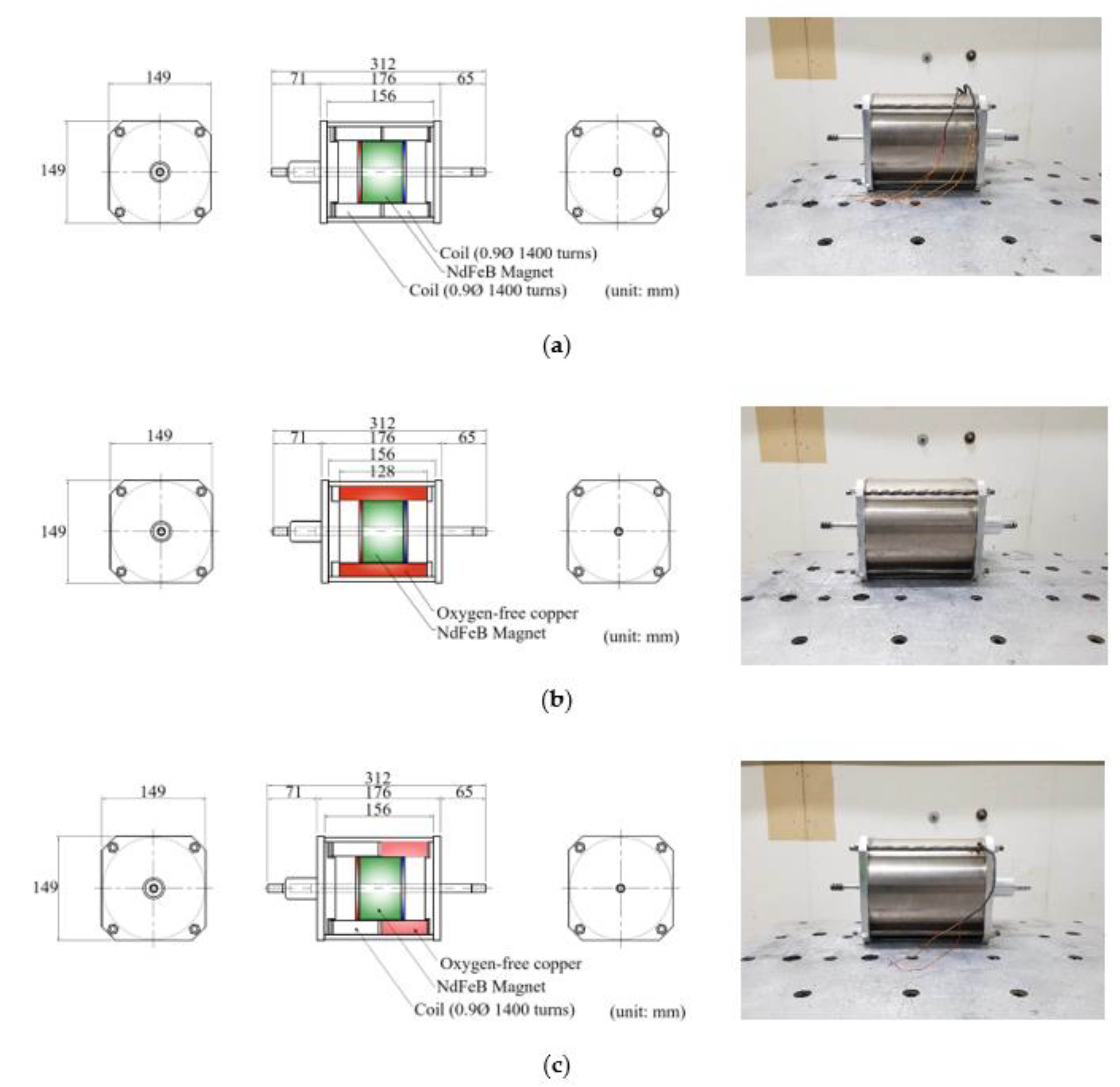
Using the coil-type electromagnetic damper as a basic model, three types of electromagnetic-damper prototypes of the eddy-current and composite types with different stator configurations were manufactured. Schematics and photographs of each damper are shown in Figure 2. All three types of electromagnetic damper were composed of an internal driver and external stator of the same size. The driver comprised an N42M-20C-grade neodymium (NdFeB) permanent magnet magnetized in the axial direction and ferromagnetic pole pieces at both ends. Because the driving part had to be moved by an external vibration, a rod attached to a controlled cable was installed in the center. All three types of electromagnetic damper had the same air gap outside of the driver.
The conductor of the stator outside the air gap was configured differently for the different types of structures. In the coil-type electromagnetic damper, two solenoid coils were arranged and separated by a bakelite insulator. In the eddy current-type electromagnetic damper, an oxygen-free copper tube was installed without a winding. In the composite-type electromagnetic damper, a solenoid coil and an oxygen-free copper tube are with the same length were installed in the axial direction. The specifications and number of turns of a single coil were identical to those for the coil-type electromagnetic damper. All three electromagnetic dampers were composed of a single magnetic circuit, as the back was made of pure iron, which functioned as a stator yoke on the outermost side.
The three electromagnetic dampers produced are shown on the right side of Figure 2. They can be distinguished by a wire strand exposed to the outside of the damper. The coil-type electromagnetic damper had four strands of exposed wires, and the composite-type electromagnetic damper had two strands, whereas the eddy current-type electromagnetic damper had no wires, because there was no coil.

3.2. Test Conditions

Shaking-table experiments were performed while changing the excitation conditions for the three types of electromagnetic dampers. The excitation conditions were determined in consideration of the damper’s design stroke length and the allowable capacity of the shaking table. The maximum stroke length for the three types of electromagnetic dampers was ±20 mm. The excitation was given as a sine wave with an amplitude of a multiple of 3 in the range of 3–12 mm and a frequency of 1–5 Hz. Additionally, excitation tests were performed in the range of 6–7 Hz and 1–4 Hz at amplitudes of 3 mm and 15 mm, respectively, while considering the performance and allowable vibration conditions of the shaking table. The sampling frequency for data collection was 100 Hz, and a 10-Hz low-pass filter was applied.
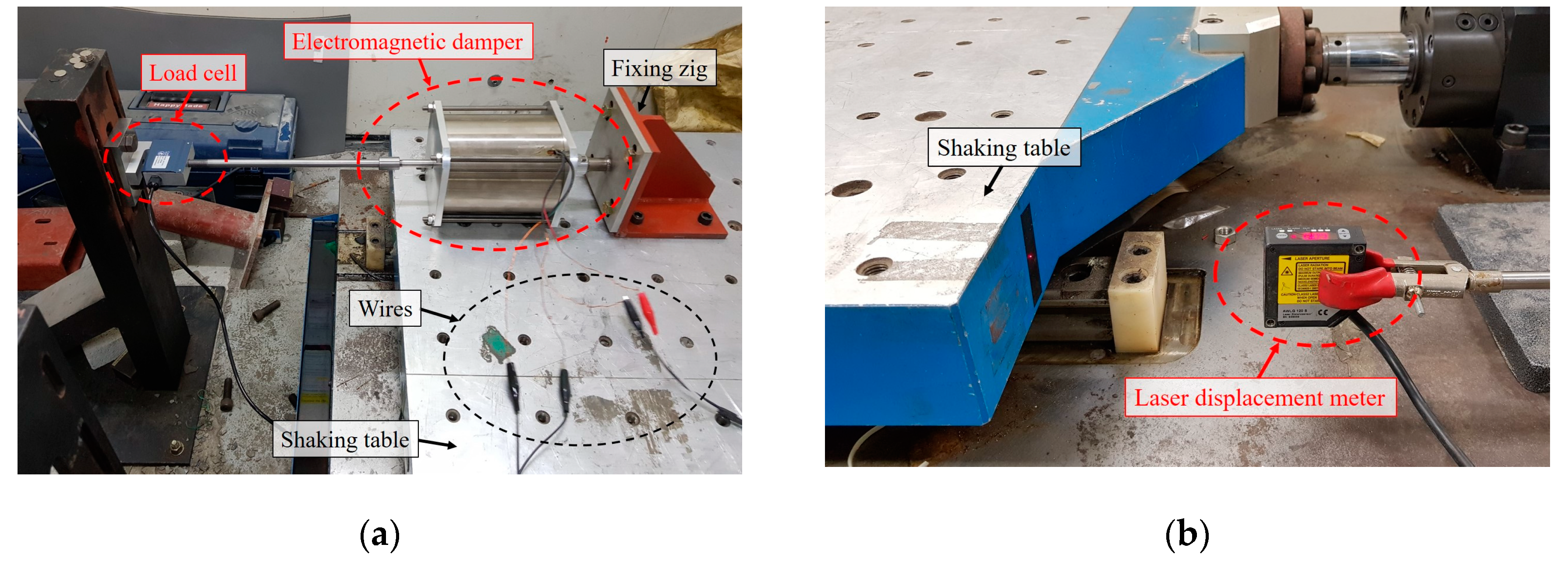
A single-axis shaking table was used for excitation. The maximum payload of the shaking table was 600 kg, the maximum stroke length was ±50 mm, the maximum dynamic force was 2 tons, and the maximum acceleration was 0.4 g (3.92 m/s2). A load cell was installed on the rod to measure the damping force acting on the electromagnetic damper. The load cell was an SB-500L model manufactured by CAS Corp. (Seoul, Korea) with a capacity of 500 kgf. The laser displacement meter used was an AWLG 120S model manufactured by WeloTec Corp. (Laer, Germany) with a measurement range of 60–180 mm, a resolution of 8 μ m , and a measurement frequency of 5000 Hz. The strain amplifier used was an STT-200S-03 model from CAS Corp. (Seoul, Korea). The dynamic data acquisition and processor used was a PXI-4461 model from National Instruments (Austin, TX, USA). Figure 3 shows the electromagnetic damper mounted on the shaking table and each measurement instrument.
Except for the eddy current-type electromagnetic damper, the coils were arranged in the stator; thus, an external circuit could be configured using wires outside the damper housing. The measured series resistance of the single coil was 13.5 Ω . When a closed circuit connected to a coil is formed, an alternating current is induced, which is affected by the resistance and inductance of the coil and the circuit. To compare the hysteresis in a state where all three electromagnetic dampers function as passive controllers, the electromagnetic dampers, including the coil type and composite type, were configured as a closed circuits without additional resistance to determine the maximum damping force.

3.3. Comparative Analysis of Test Results

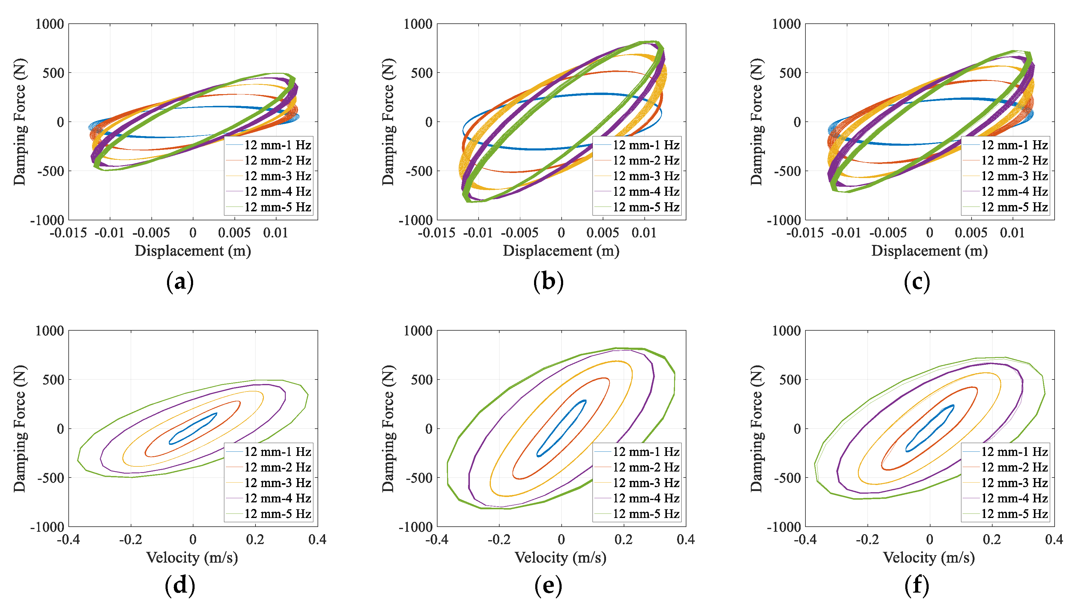
The hysteresis loops for the displacement and speed of the three types of electromagnetic dampers all exhibited an elliptical shape closer to that for a viscoelastic solid damper than to that for a viscous fluid damper [19]. Under the same excitation conditions, the damping force was the weakest for the coil type and the strongest for the eddy current-type.
The hysteresis loops indicating the displacement–force and velocity–force relationships according to the excitation frequency for the coil-, eddy current-, and composite-type electromagnetic dampers at an excitation amplitude of 12 mm are shown in Figure 4. For all the electromagnetic dampers, the damping force increased as the excitation frequency increased under a constant excitation amplitude. In the displacement–force loops, the inclination of the major axis increased as the maximum damping force increased. The relative energy dissipation was evaluated according to the area of the ellipse where the displacement–force loop appeared [20]. The area of the ellipse increased and the energy dissipation of the damper increased as the inclination and length of the major axis increased as the excitation frequency increased. The displacement value at which the maximum damping force occurred gradually increased as the excitation frequency increased, and it tended to approach the maximum displacement value.
In contrast, as indicated by the velocity–force loops of the electromagnetic dampers, as the excitation frequency increased, the lengths of the major and minor axes of the ellipse increased, and the area increased, but the major-axis inclination decreased. The slope of the major axis of the ellipse was related to the damping coefficient of the damper. Therefore, the damping coefficient decreased as the excitation frequency increased. As the eddy current-type electromagnetic damper had an excitation frequency of 5 Hz, the maximum damping force hardly increased, and the damping coefficient tended to decrease significantly. In contrast, for the coil-type electromagnetic damper, a moderate reduction was observed. It was confirmed that if the conductor density is low, the absolute magnitude of the damping force is small but can correspond to a relatively high frequency range.
The hysteresis loops caused by the amplitude change when the electromagnetic dampers were all excited at the same frequency (5 Hz), are shown in Figure 5. All the electromagnetic dampers exhibited a constant increase in the damping force as the excitation amplitude increased. However, in contrast to the case of the changing excitation frequency, as the excitation amplitude increased, the ellipse appeared to extend almost uniformly in the major- and minor-axis directions. Thus, the amount of energy dissipated by the electromagnetic dampers within the excitation range was affected more significantly by the excitation amplitude than by the excitation frequency.
As indicated by the velocity–force loops of the dampers, the inclination of the major axis remained almost constant even when the excitation amplitude increased. Therefore, the excitation-amplitude changes hardly affected the damping coefficient. The convergence of the maximum damping force and the reduction in the damping coefficient did not occur when the excitation frequency was changed. Therefore, to determine the required damping coefficient, the amplitude of the cable in the real wind environment and the driving stroke length of the damper should be considered. However, because the stroke length of the damper affects the lengths of the permanent magnet, coil, and magnetic material, these factors must be considered together.
The changes in the maximum damping force with respect to the excitation amplitude and excitation frequency of the electromagnetic dampers are shown in Figure 6 on the same y-axis scale. For all the electromagnetic dampers, the maximum damping force increased linearly as the excitation amplitude increased at a constant excitation frequency. However, at a constant excitation amplitude, the maximum damping force exhibited a non-linear increase with an increase in the excitation frequency. The convergence of the maximum damping force was most pronounced (and the damping force was strongest) for the eddy current-type electromagnetic damper.
The maximum damping force when the eddy current-type electromagnetic damper was excited at an amplitude of 12 mm and a frequency of 5 Hz was increased by 28.36 N (4%) compared with that for the same amplitude and a frequency of 4 Hz. This was the smallest increase among the three dampers under the same excitation conditions. The eddy current-type electromagnetic damper had a stronger damping force than the other dampers under the same excitation conditions but approached the maximum damping force at a relatively low frequency. Therefore, it is necessary to design a damper with consideration of the corresponding frequency range.
The results of comparing the velocity–force hysteresis loops under different excitation conditions are shown in Figure 7. When the excitation amplitude and frequency were small and low, respectively, the non-linearities and delays of loading and non-loading were significant. The effect of the error due to the friction of the drive shaft and the noise of the shaking table was observed. The history of motion was similar to that for the magnetorheological (MR) fluid damper, where shear and yield stresses act. As the excitation frequency and amplitude increased, the history became elliptical, similar to that for a viscoelastic damper.
A comparison of Figure 7b,c confirmed that a larger excitation amplitude corresponded to greater similarity between the damping forces of the composite- and eddy current-type dampers. This is because the increase rates of the damping force for the eddy current- and coil-type dampers were relatively low, and that of the damping force for the composite-type damper was relatively high. Previously, it was confirmed that the increase rate decreases as the eddy current-type electromagnetic damper force approaches the maximum damping force when the excitation amplitude and frequency are increased.
However, when the maximum damping force at an excitation frequency of 4 Hz and an excitation amplitude of 15 mm was compared with that at an amplitude of 3 mm, increments by factors of 4.3, 4.3, and 4.9 were observed for the eddy current-, coil-, and composite-type dampers, respectively. This implies that the excitation conditions cannot be presumed to be the cause for the convergence of the eddy-current type damping force and the maximum damping force. Hence, it was confirmed that to reinforce the damping force using the eddy current, it is necessary to limit the degree of contribution of the damping force due to the eddy current with consideration of the desired maximum damping force and the rate of increase in the damping force due to the strengthening of the excitation conditions. This is a major consideration in design, because the coil and oxygen-free copper tube must be placed together to ensure controllability and enhance the damping force.
The comparison results for the maximum damping forces of the three electromagnetic dampers under the same excitation conditions (frequency and amplitude) are shown in Figure 8. For all three dampers, as the excitation amplitude increased, the maximum damping force increased linearly. In contrast, as the excitation frequency increased, the maximum damping force increased non-linearly. For the composite- and coil-type dampers, the maximum damping force varied but remained within the ranges of 78–88% and 58–60%, respectively, of that for the eddy current-type damper.
The maximum damping forces of the three types of electromagnetic damper in the excitation test are presented in Table 3. Because the shaking table could not be excited under certain amplitude conditions (≥5 Hz), the excitation range was set with consideration of the allowable capacity of the shaking table. The three electromagnetic dampers exhibited the maximum damping forces when the excitation amplitude was 15 mm and the excitation frequency was 4 Hz. The maximum damping forces of the composite and coil types were 88% and 60%, respectively, of that of the eddy-current type. Remarkably, the maximum damping force when the eddy current-type electromagnetic damper was excited with an amplitude of 3 mm and a frequency of 7 Hz was 1.83 N weaker than that when the damper was excited at a frequency of 6 Hz.
In contrast, the coil-type electromagnetic damper did not exhibit a reduction in the maximum damping force under the same excitation conditions. However, when the frequency is ≥8 Hz, the maximum damping force is expected to decrease. Therefore, it is necessary to prevent the magnetic saturation of the pole pieces and magnetic body, as well as magnetic imbalance. In the coil-type electromagnetic damper used in the test, the stator coils were arranged in a slotless structure; thus, there was no eddy current loss [21].
Analysis of the foregoing results revealed an effective design direction for applying electromagnetic dampers in the field of civil engineering. It is necessary to improve the damping performance using the eddy current while maintaining controllability using the coil. Additionally, it is necessary to determine the driving stroke with consideration of the frequency and amplitude to be countered and to arrange the conductors and magnetic bodies. However, when applying a slot or bridge to reinforce the damping force, it is necessary to consider cogging [22]. In general, considering that the frequency band of civil structures including cables of bridges is lower than that of motors in the mechanical field, there is a concern that the non-uniform characteristics will appear more prominently. Therefore, it is necessary to configure the magnetic circuit so that the magnetic attraction generated at the end of the slot or bridge is not concentrated during driving and the magnetic flux is evenly distributed between the coil and the slot.

4. Electromagnetic Analysis of the Proposed Damper

According to the results of the characteristic tests, an RHED with controllable and improved damping performance was designed. An electromagnetic finite element analysis was performed to predict the dynamic behavior and investigate the electromagnetic characteristics. For the simulation based on finite element analysis, ANSYS Electromagnetics suite (ver. 19.2, official license), a commercial analysis program widely used for magnetic and electric field analysis, was used.

4.1. Design Orientation and Model Configuration

Coil-type electromagnetic dampers can be controlled actively, passively, or semi-actively, but need reinforcement in terms of damping force. In contrast, the eddy current-type electromagnetic damper has a strong damping force, but has a limit that can only be controlled passively. An eclectic type of damper was proposed, where the damping level was increased while combining the functions and advantages of coil-type and eddy current-type electromagnetic dampers. The damping level depended on the maximum damping force and damping density [23].
The drive part of the proposed damper is constrained by steel rods, permanent magnets, and pole pieces that move linearly under external excitation. In the stator surrounding the driving part, a coil for the control function, an oxygen-free copper tube for generating eddy currents, and a stator tooth for reinforcing the damping force were arranged. The outermost side of the stator was surrounded by an iron shell and functioned as a stator yoke, forming a magnetic circuit. The shape and analysis model of the proposed damper are shown in Figure 9.
The driving part comprised permanent magnets magnetized in the axial direction and pole shoes that induced a magnetic flux in the radial direction [24,25]. Because the permanent magnets maintained a permanent magnetization state when magnetized, they could be maintained without losing magnetic force or receiving electrical energy from an external source. These features are advantageous for use in semi-permanent attenuator development and monitoring-system construction. Among the magnets currently used as permanent magnets, neodymium (NdFeB) magnets used have the strongest magnetic force [26]. A neodymium magnet has good processability and a relatively low price but rusts easily; thus, it is usually plated with nickel. However, there is a disadvantage: the magnetism is weakened by heat owing to the low temperature coefficient [27]. Therefore, the magnet grade should be determined according to the temperature of the environment in which the damper is to be installed.
The width of the air gap is a critical variable influencing the absolute magnitude of the damping force [28,29,30]. The width of the air gap was set as 0.5 mm (the minimum length for ensuring permanent operation), as it is feasible to manufacture a prototype with a constant width in the axial direction. The stator located outside the air gap comprised two solenoid coils, an oxygen-free copper tube, and an outer shell [31]. The coils reduced the absolute damping force owing to series resistance and inductance, but were essential for circuit construction and control. Each coil was insulated and separated.
In addition to the coils, the stator was provided with an oxygen-free copper tube and regularly spaced teeth to increase the damping force [32]. The oxygen-free copper placed in the proposed tubular structure and the adjacent teeth facing the iron pieces reinforced the damping force by inducing eddy currents.
The damper was physically and magnetically affected by the configuration of the circuit connected to the coil. For passive control, a circuit was constructed by assuming a closed circuit and synchronizing each coil with an inductor and a measured series resistor. The circuit diagram is shown in Figure 9c.

4.2. Analysis Conditions

The drive part of the proposed damper performs translational motion, and the non-linear material properties of the permanent magnet should be considered. Additionally, the magnetic field due to the effect of the induced current on the surface should be considered. Therefore, a transient analysis was performed. The geometry of the damper’s finite-element model was modeled in two dimensions and rotated 360° around the z-axis.
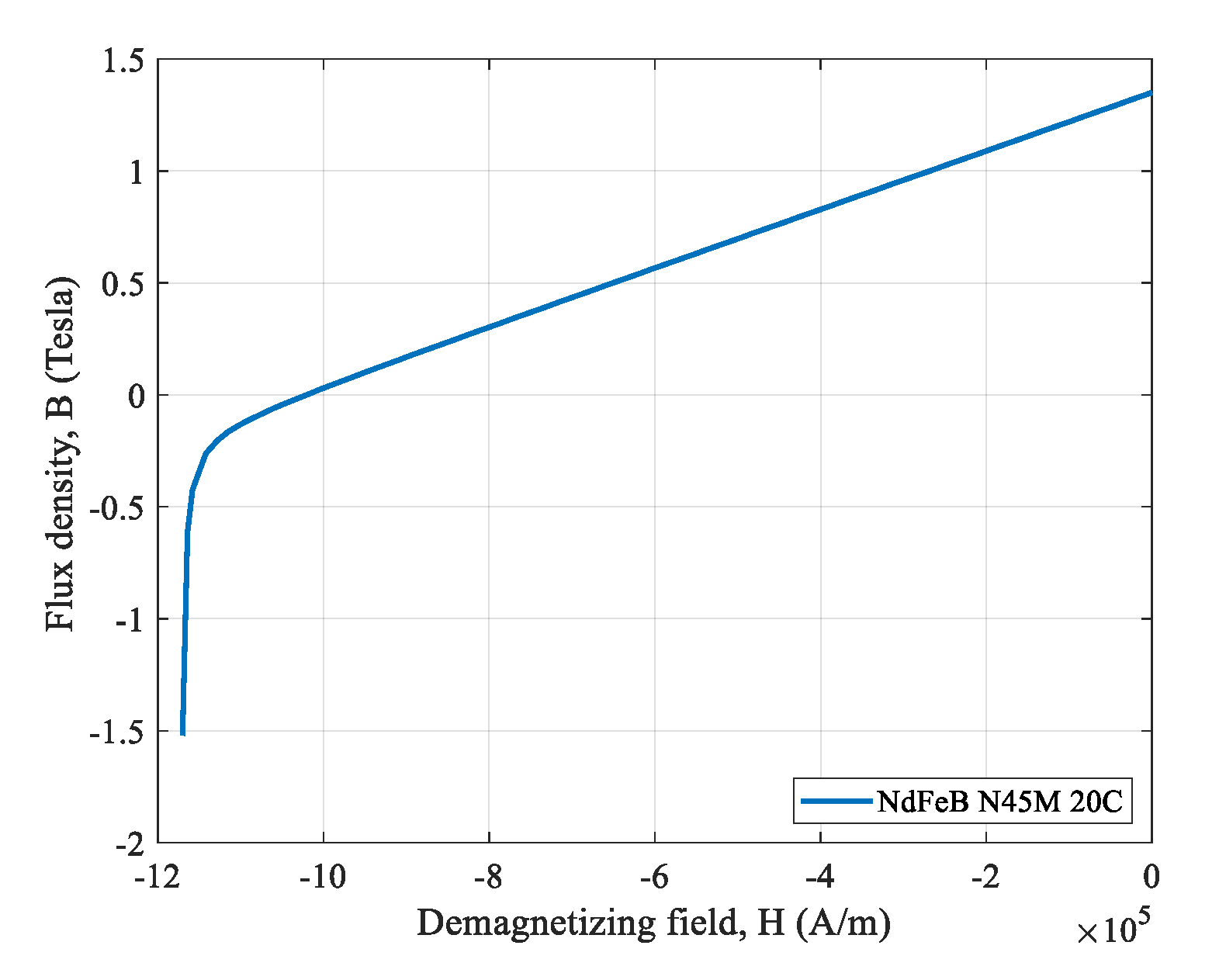
The neodymium used as the permanent magnet of the proposed damper was N45M-20C grade and from Arnold Magnetic Technologies Corp. (Rochester, NY, USA). The demagnetization curve indicating the non-linear relative permeability is shown in Figure 10. Other important non-linear attributes are presented in Table 4.
By placing pole pieces made of pure iron at the boundary between the magnets and at both ends of the driver, the magnetic path loss was minimized, and the magnetic flux was guided in the radial direction. The relative permeability of pure iron used in the analysis was 4000, and the bulk conductivity was 10,300,000 S/m.
It was assumed that the solenoid coils consisted of individually insulated conductors such that the eddy current was negligible. Therefore, the eddy current and displacement current inside the conductor were not calculated, and the current density was assumed to be uniform throughout the conductor. The diameter of each solenoid coil was 0.7 mm, and the number of turns was 625. According to the actual measurements, the series resistance of the coil was 6.5 (±0.1) Ω.
Both the coils and the oxygen-free copper tube were assumed to be made of copper. The relative permeability used in the analysis was 0.999991, and the bulk conductivity was 58,000,000 S/m. The intermeshed teeth structures were assumed to be made of copper and pure iron, respectively. In the tooth structure, the part made of pure iron was combined with the outermost shell, which was assumed to be made of the same material.
To manufacture an actual damper prototype and conduct an experiment with it, a rod had to be fixed to a permanent magnet. Additionally, perforated covers and bearings at both ends were needed to constrain the rod stroke. These components were assumed to be made of aluminum and stainless steel. Because these components are non-magnetic, they were not considered in the electromagnetic analysis. Additionally, it was assumed that each component of the damper had no deformation due to the magnetic field. Therefore, the Young’s modulus, Poisson’s ratio, and magnetostriction were not considered.
The analysis region was set to 100% offset of the damper dimension in each axial direction considering the magnetic material of the model. Vacuum conditions were assumed for the space outside the damper, the clearance for the stroke of the drive, and the air gap. To implement translational motion in the driving part, permanent magnets and pole pieces were wrapped to restrain them from moving integrally under external excitation. The tied part was made to move in the z-axis inside the band that realized the stroke space of the driving part. The excitation was a sinusoidal wave with an amplitude of 12 mm and a frequency of 5 Hz. A transient analysis was performed in an adaptive time step with a time interval of at least 0.001 s. The analysis was performed for two cycles of excitation.

4.3. Analysis Results

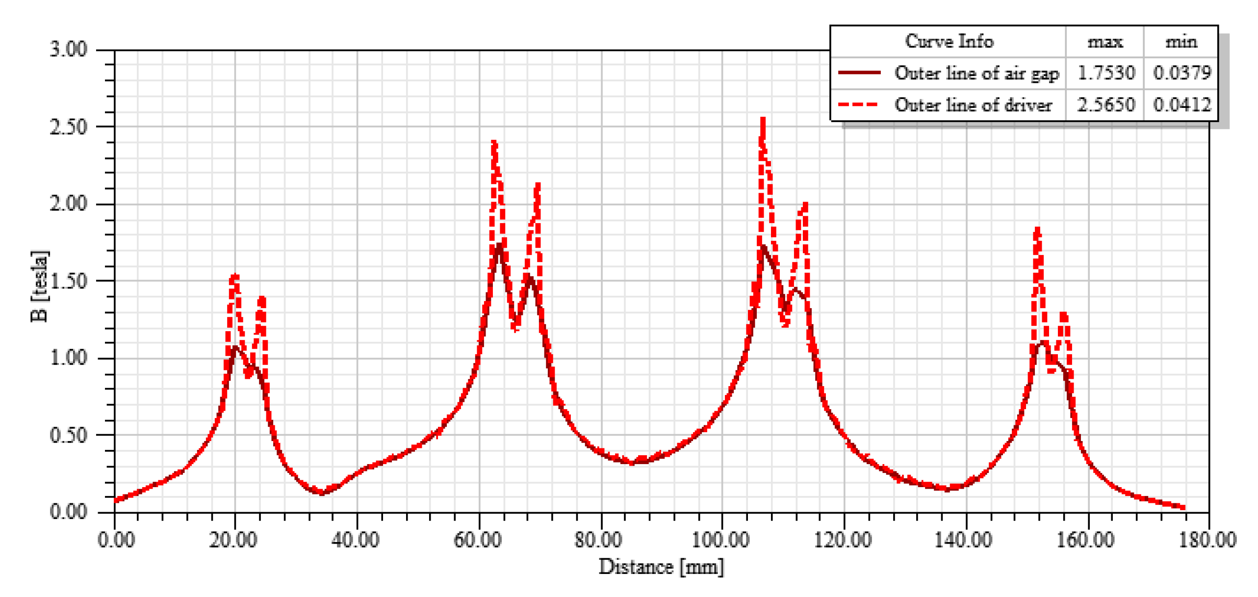
The magnetic-field distribution in the air gap by the driver was examined [33]. With consideration of the magnetic saturation, the thickness of the pole pieces was adjusted so that the maximum magnetic flux density outside the air gap was distributed in the range of 1.5–2.0 T. Figure 11 shows the magnetic flux density along the axial length inside and outside the air gap. The potential was maximized when the thickness of the inner and outer pole pieces were 7 and 5 mm, respectively.
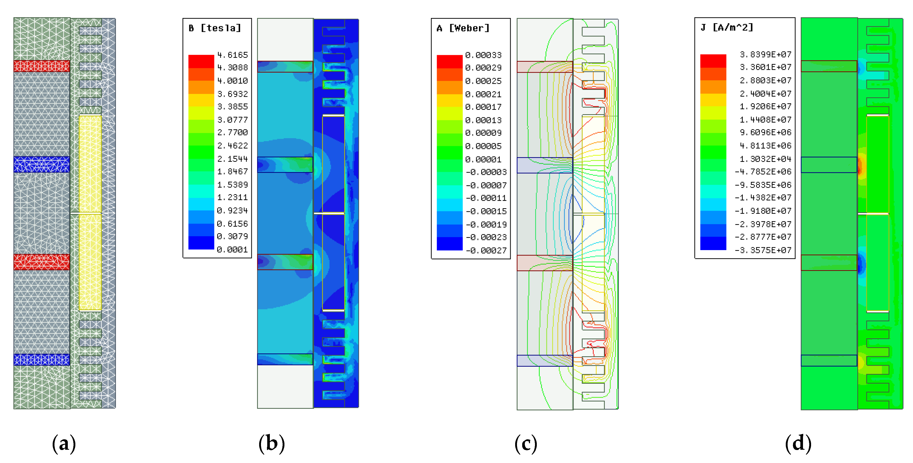
For the mesh of the transient analysis model, the conditions for magnetostatic analysis were applied to all the components of the damper and the band of the stroke space. In the magnetostatic analysis, the mesh was applied considering the density of the pole pieces and the air gap [34,35]. The maximum length of each element was 0.004 m, and the maximum number of elements was 1000. The faces, edges, etc. of each object were all divided equally. Copper modeled as a coil has high conductivity, but has little effect on penetration depth; thus, a skin-depth mesh was not considered. The mesh configuration applied to the damper model is shown in Figure 12a.
Figure 12b shows the distribution of the magnetic flux density at the maximum motion force, when the periodic motion of the driving part was stabilized and neutral. The magnetic flux density was concentrated on the teeth outside the pole pieces and on the magnetic path and exhibited a vertically symmetrical distribution. The maximum magnetic flux density appeared along the interface of the teeth facing the pole pieces. Low magnetic flux densities of ≤1 T were observed in the back iron of the magnetic path passing through the activated coils.
The distribution of the magnetic flux lines is shown in Figure 12c, confirming the formation of magnetic circuits. The magnetic flux lines of the permanent magnets and pole pieces exhibited a dense distribution as they approached the stator. The strongest and most dense magnetic flux distribution was observed in the teeth located on the magnetic path, which faced the pole pieces as the driver moved. Conversely, the weakest magnetic flux distribution was observed on the inner paths of the activated coils and flux lines in the back iron. Additionally, magnetic flux lines appeared on a short path through the slot in which the insulating material was disposed between the coils.
The current-density distribution is shown in Figure 12d. The damper windings were assumed to be stranded models. Therefore, since there was no skin depth and solid loss did not occur, a uniform current flowed through the coil cross-section. The coils exhibited a uniform density distribution and a concentrated distribution in the conductor, where each pole piece was located.
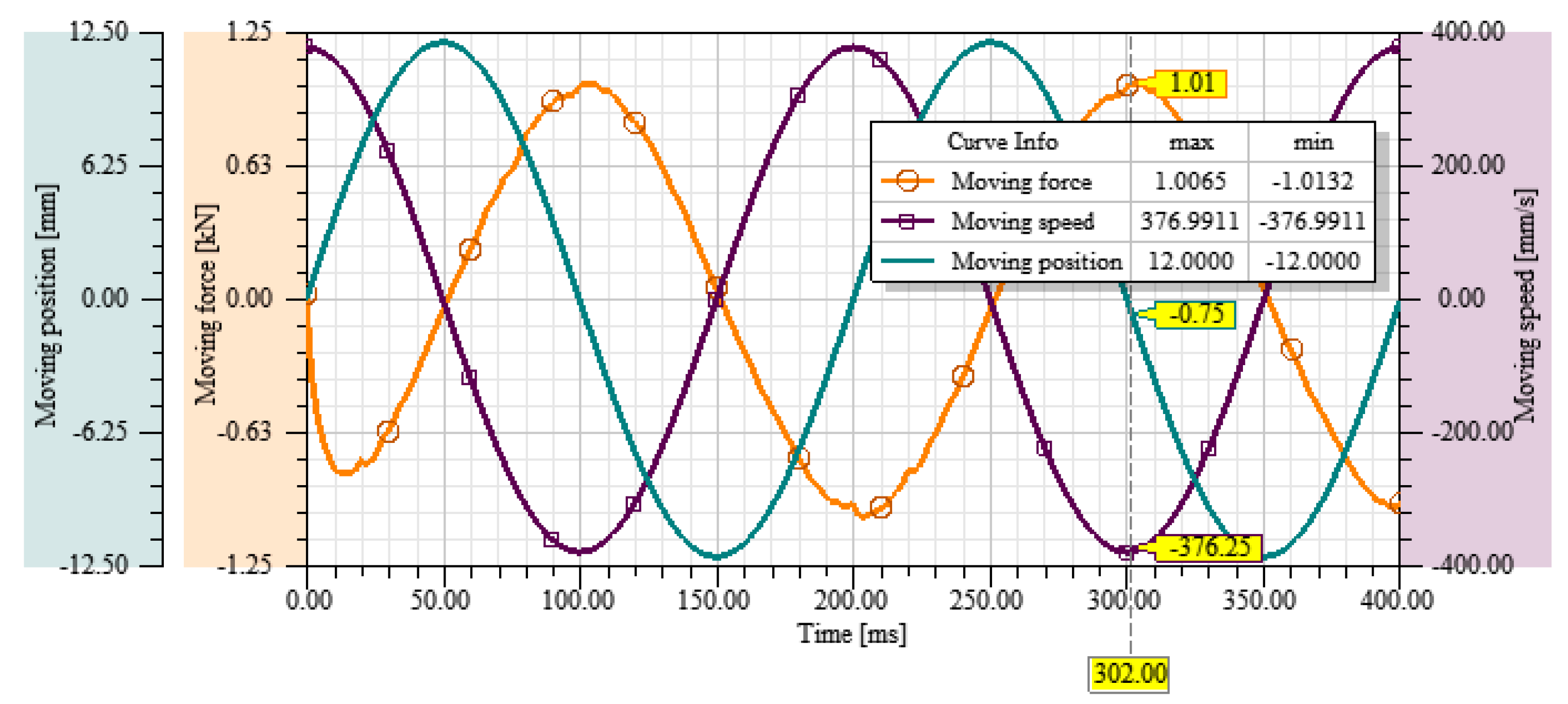
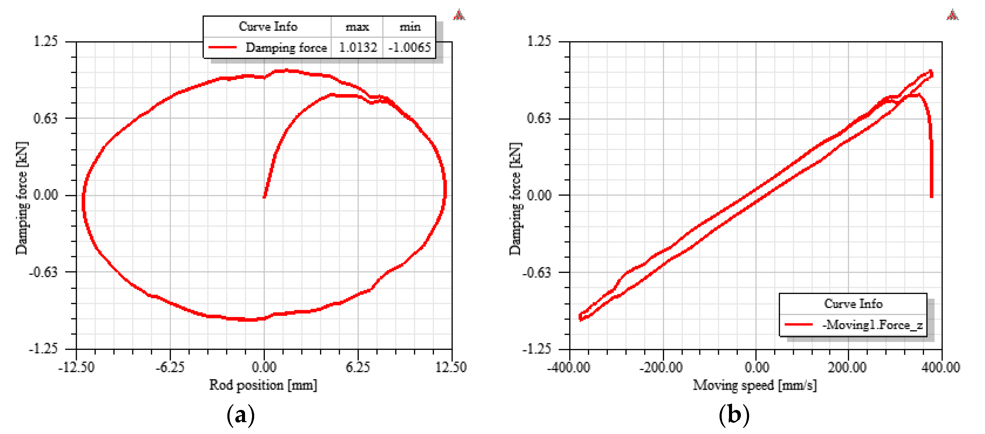
To examine the changes in the damping force of the proposed damper, the motion force acting on the driver during a period of two cycles was investigated. The position, speed, and force of the driver over time are shown in Figure 13. The driving force changed periodically with the changes in the position and speed. As the speed increased, the force increased and acted in the opposite direction to the movement of the driver, because the force was generated in a direction to resist changes in the magnetic flux. The maximum damping force exhibited a delay of ≥10 ms. A weak damping force was observed at the beginning of the driving, but the damping force stabilized rapidly from the second cycle onwards. After a delay of 2 ms, a constant period and damping force magnitude appeared. The maximum damping force was 1.01 kN when the speed of the damper was 376.99 mm/s, which was 88% stronger than that of the coil-type electromagnetic damper and 20% stronger than that of the composite-type electromagnetic damper.
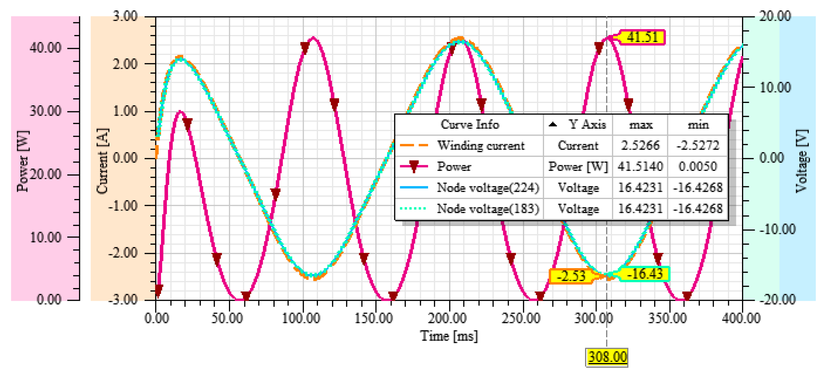
The electrical characteristics of the damper model affected the energy-harvesting performance. Figure 14 shows the induced current, induced voltage, and power of the circuit connected to the damper with respect to time. The induced voltages of the windings were generated by an alternating electromotive force, and the maximum voltage was 16.42 V. The maximum current flowing through the circuit was 2.53 A, and the voltage and current waveforms applied to the respective coils (resistance nodes #224 and #183) exhibited almost identical changes. The maximum power of the winding was calculated to be 41.51 W.
In the current measurement test for the coil-type electromagnetic damper, the maximum current and power were 1.31 A and 23.32 W, respectively. The maximum current and power of the proposed damper were 93% and 78% higher, respectively, than those of the coil-type electromagnetic damper. The feasibility of energy harvesting based on the wind-speed data measured on a cable of a real bridge was evaluated using the coil-type electromagnetic damper prototype employed in this study [36]. According to a previous study, the generated power of the proposed damper model satisfies the power required for vibration monitoring of the cable. However, because the amount of power of the proposed damper model is an analytically derived value, it is necessary to examine the loss and efficiency when implementing an energy-harvesting circuit including a storage battery.
Changes in the flux linkage of the windings affect the driving force, inductance, and induced electromotive force of the damper [37]. The function of the winding in the proposed damper was to ensure controllability, but when the energy-harvesting performance was first considered, it was necessary to determine the number of turns of the coil according to the voltage to be induced and the amount of power required. Figure 15 shows the changes in flux linkage and inductance of the two windings over time. The maximum flux linkages of the windings were 0.59 Wb and 0.39 Wb. The flux linkages changed with the same period as the excitation, while maintaining a constant difference of 0.2 Wb.
The average self-inductance of the windings calculated according to the flux linkage was 29.96 mH, and the mutual inductance was 6.67 mH. Changes of ≤0.37 and ≤0.05 mH, respectively, were observed; thus, the values remained almost constant over time.
The amount of magnetic flux per unit current varies according to the inductance and affects the damping force of the damper. Additionally, the damping coefficient of the electromagnetic damper is affected by not only the inductance of the winding but also the damper’s device constant, circuit resistance, and excitation frequency. Hysteresis curves indicating the damping force according to the displacement and speed of the proposed damper are presented in Figure 16.
The hysteresis loop of the proposed damper model was similar to that of a viscous fluid damper. Compared with the previously discussed electromagnetic dampers, the amount of dissipated energy was relatively large, and the damping coefficient remained almost constant. The estimated damping coefficient was 2687.60 N·s/m, representing an improvement of approximately 80% compared with the damping coefficient (1491.55 N·s/m) estimated according to the major-axis slope of the composite-type electromagnetic damper under the same excitation conditions.
In general, as the coil inductance decreased, the ellipse reflecting the velocity–force relationship became thinner (while maintaining a constant slope) and eventually approximated a straight line [38]. Therefore, the damping coefficient did not change, but the maximum damping force increased slightly.
The shape of the ellipse reflecting the velocity–force relationship of the damper also depended on the circuit resistance. As the resistance increased, the slope decreased, and the ellipse became thinner. Thus, both the damping coefficient and the damping force decreased. The results of the proposed damper indicate that the effect of the inductance is less than the winding resistance.

5. Conclusions

Through a magnetic-circuit analysis of an electromagnetic-damper model, major equations related to the dynamic behavior and performance of the damper were derived, including equations for the magnetic flux of the damper, the electromotive force induced in the active coil, and the total damping force of the damper. Additionally, characteristic tests were conducted on prototypes of electromagnetic dampers with different stator structures, including coil-type electromagnetic dampers, to which the optimal values for the main parameters were applied, to examine the hysteretic dynamics according to the excitation conditions and structure types.
For all the dampers, as the excitation frequency increased, the amount of dissipated energy and the damping force increased non-linearly, but the damping coefficient decreased slightly. As the excitation amplitude increased, the amount of dissipated energy increased significantly, and the damping force increased linearly, but the damping coefficient remained almost constant.
The eddy current-type electromagnetic damper exhibited the best damping performance among the dampers under the same excitation conditions, but as the excitation conditions were strengthened, the damping force and damping coefficient approached the maximum values and tended to converge. The damping force began to decrease after the frequency reached a certain value, and strong convergence was confirmed. The maximum damping forces for the coil-type and composite-type electromagnetic dampers were 60% and 80%, respectively, of those for the eddy current-type electromagnetic damper.
According to the considerations of the electromagnetic-damper model and the characteristics test results, an RHED was proposed that can apply various control methods, allow energy harvesting through self-generation, and exhibit improved damping performance compared to typical electromagnetic dampers. The physical and electromagnetic behaviors and characteristics of the proposed damper model were examined through electromagnetic finite element analysis.
The results confirmed that the enhancements in the damping and energy-harvesting performance were due to pole shoes considering magnetic saturation, the tubular oxygen-free copper inside the stator, and the magnetic paths utilizing the teeth structure. The maximum damping force of the proposed RHED model was 1.01 kN, and the estimated damping coefficient was 2687.60 N·s/m, which was improved by ≥80% compared with a controllable coil or composite-type electromagnetic damper.
The maximum induction voltage and production power of the RHED model were 16.43 V and 41.51 W, respectively. This production power is sufficient to build a vibration monitoring system for cables according to a previous study on the feasibility of energy harvesting using the same coil-type electromagnetic damper, wind vibration data for the cable of an actual bridge, and wireless sensors. However, it is necessary to consider that the actual wind environment is not the condition of having a constant wave excitation, such as in experiments or simulations.
When implementing an actual energy-harvesting circuit including a storage battery, it is necessary to examine the loss and efficiency. Additionally, because the hysteresis-loop analysis results indicate that the resistance value for inductance is relatively large, it is expected that the attenuation performance can be improved by optimizing the winding design according to the required voltage and power.
Through this study, we proposed an electromagnetic damper, a key element in realizing an autonomous damping and vibration monitoring system, and analyzed the feasibility of an improved damper model. It is necessary to verify the performance experimentally in the future by connecting the energy-harvesting circuit, including the control circuit, and analyzing the prototype applied to the cable. The proposed damper and system are expected to play an important role in the cable maintenance field of bridges through continuous improvement and practicality research.

Author Contributions

Conceptualization, S.K.; methodology, S.K.; validation, S.K. and H.-J.J.; formal analysis, S.K.; investigation, S.K.; resources, S.K.; data curation, S.K.; writing—original draft preparation, S.K.; writing—review and editing, S.K. and H.-J.J.; visualization, S.K.; supervision, H.-J.J.; project administration, H.-J.J.; funding acquisition, H.-J.J. All authors have read and agreed to the published version of the manuscript.

Funding

This research received no external funding.

Acknowledgments

This work was supported by the National Research Foundation of Korea (NRF) grant funded by the Korean government (MSIT) (No. 2017R1A5A1014883 and NRF-2019R1A2C2007835).

Conflicts of Interest

The authors declare no conflict of interest.

References

  1. Kim, S.; Park, J.; Kim, H.K. Damping Identification and Serviceability Assessment of a Cable-Stayed Bridge Based on Operational Monitoring Data. J. Bridge Eng. 2017, 22, 04016123. [Google Scholar] [CrossRef]
  2. Park, K.J.; Hwang, E.S. Assessment of Vibration Serviceability for Steel Cable-Stayed Bridges Using GNSS Data. Int. J. Steel Struct. 2016, 16, 1251–1262. [Google Scholar] [CrossRef]
  3. Li, H.; Ou, J. The state of the art in structural health monitoring of cable-stayed bridges. J. Civ. Struct. Health Monit. 2016, 6, 43–67. [Google Scholar] [CrossRef]
  4. Jiang, C.; Wu, C.; Cai, C.S.; Jiang, X.; Xiong, W. Corrosion fatigue analysis of stay cables under combined loads of random traffic and wind. Eng. Struct. 2020, 206, 110153. [Google Scholar] [CrossRef]
  5. Park, C. Detail Planning Research Project on Super-Long Span Cable Bridge; Korea Expressway Corporation: Seongnam, Korea, 2008; p. 688. [Google Scholar]
  6. Wang, J.; Howe, D.; Jewell, G.W. Analysis and Design Optimization of an Improved Axially Magnetized Tubular Permanent-Magnet Machine. IEEE Trans. Energy Convers. 2004, 19, 289–295. [Google Scholar] [CrossRef] [Green Version]
  7. Ebrahimi, B.; Khamesee, M.B.; Golnaraghi, M.F. Feasibility Study of an Electromagnetic Shock Absorber with Position Sensing Capability. In Proceedings of the 2008 34th Annual Conference of IEEE Industrial Electronics, Orlando, FL, USA, 10–13 November 2008. [Google Scholar]
  8. Wang, Z.; Hua, G. Feasibility Study of Passive Electromagnetic Dampers for Vibration Control of Stay Cables. Appl. Mech. Mater. 2013, 438–439, 1141–1144. [Google Scholar] [CrossRef]
  9. Jamshidi, M.; Chang, C.C.; Bakhshi, A. Self-powered hybrid electromagnetic damper for cable vibration mitigation. Smart Struct. Syst. 2017, 20, 285–301. [Google Scholar] [CrossRef]
  10. Zuo, L.; Chen, X.; Nayfeh, S. Design and Analysis of a New Type of Electromagnetic Damper With Increased Energy Density. J. Vib. Acoust. 2011, 133, 041006. [Google Scholar] [CrossRef]
  11. Palomera-Arias, R. Passive Electromagnetic Damping Device for Motion Control of Building Structures. Ph.D. Thesis, Massachusetts Institute of Technology, Cambridge, MA, USA, 2005. [Google Scholar]
  12. Furlani, E.P. Permanent Magnet and Electromechanical Devices-Materials, Analysis, and Applications, 1st ed.; Academic Press: San Diego, CA, USA, 2001. [Google Scholar]
  13. Griffiths, D.J. Introduction to Electrodynamics, 3rd ed.; Prentice Hall: Upper Saddle River, NJ, USA, 1999. [Google Scholar]
  14. Zhang, C.; Chen, Z.; Wang, L. An investigation on the field strength and loading rate dependences of the hysteretic dynamics of magnetorheological dampers. Mech. Time-Depend. Mater. 2014, 19, 61–74. [Google Scholar] [CrossRef]
  15. Zheng, J.; Zhang, C.; Li, A. Experimental Investigation on the Mechanical Properties of Curved Metallic Plate Dampers. Appl. Sci. 2020, 10, 269. [Google Scholar] [CrossRef] [Green Version]
  16. Dominguez, A.; Sedaghati, R.; Stiharu, I. Modelling the hysteresis phenomenon of magnetorheological dampers. Smart Mater. Struct. 2004, 13, 1351–1361. [Google Scholar] [CrossRef]
  17. Jung, H.Y. Feasibility Study of Multifunctional Electromagnetic Damper for Vibration Control of Cable and Energy Harvesting. Ph.D. Thesis, Korea Advanced Institute of Science and Technology, Daejeon, Korea, 2018. [Google Scholar]
  18. Jung, H.Y.; Kim, I.H.; Jung, H.J. Feasibility Study of the Electromagnetic Damper for Cable Structures Using Real-Time Hybrid Simulation. Sensors 2017, 17, 2499. [Google Scholar] [CrossRef] [PubMed] [Green Version]
  19. Soong, T.T.; Dargush, G.F. Passive Energy Dissipation Systems in Structural Engineering; John Wiley & Sons Ltd.: Chichester, UK, 1997. [Google Scholar]
  20. Zhao, Z.; Zhang, R.; Jiang, Y.; De Domenico, D.; Pan, C. Displacement-Dependent Damping Inerter System for Seismic Response Control. Appl. Sci. 2019, 10, 257. [Google Scholar] [CrossRef] [Green Version]
  21. Kim, J.B.; Jeong, S.S. Characteristics of linear reciprocating motor applying ferrite magnet. In Proceedings of the KIEE Summer Conference 2017, Jeollanam-do, Korea, 12–14 July 2017. [Google Scholar]
  22. Lee, J.; Lee, J.; Ha, J.I. On-line Tracking of Harmonic Torque Feedforward for Torque Ripple Reduction of PMSM. In Proceedings of the Power Electronics Annual Conference, Seoul, Korea, 22 November 2019. [Google Scholar]
  23. Kye, S. Regenerative Hybrid Electrodynamic Damper for Stay Cables. Ph.D. Thesis, Korea Advanced Institute of Science and Technology, Daejeon, Korea, 2020. [Google Scholar]
  24. Jung, S.J.; Lee, J. Characteristic Analysis and Test of IPMSM for e-4WD of the Hybrid Electric Vehicle. Trans. Korean Inst. Electr. Eng. 2016, 65, 777–784. [Google Scholar] [CrossRef]
  25. Glinka, T.; Bernatt, J. Asynchronous slip-ring motor synchronized with permanent magnets. Arch. Electr. Eng. 2017, 66, 199–206. [Google Scholar] [CrossRef]
  26. Basak, A.; Shirkoohi, G.H. Computation of magnetic field in DC brushless linear motors built with NdFeB magnets. IEEE Trans. Magn. 1990, 26, 948–951. [Google Scholar] [CrossRef]
  27. Park, Y.B.; Kim, J.W.; Lee, J.S. Study on Magnetic Property for Test Coil and Permanent Magnet. J. Korean Magn. Soc. 2016, 26, 154–158. [Google Scholar] [CrossRef] [Green Version]
  28. Kim, C.E.; Lee, S.H. Design and Analysis of Permanent Magnet Double-Sided Linear Synchronous Motor with Perpendicular Arrangement. J. Korean Inst. IIIum. Electr. Install. Eng. 2013, 27, 62–73. [Google Scholar] [CrossRef]
  29. Bianchi, N. Analytical Field Computation of a Tubular Permanent-Magnet Linear Motor. IEEE Trans. Magn. 2000, 36, 3798–3801. [Google Scholar] [CrossRef]
  30. Lee, J.; Lee, J. Magnetic Force Enhancement Using Air-Gap Magnetic Field Manipulation by Optimized Coil Currents. Appl. Sci. 2019, 10, 104. [Google Scholar] [CrossRef] [Green Version]
  31. Pan, Q.; He, T.; Xiao, D.; Liu, X. Design and Damping Analysis of a New Eddy Current Damper for Aerospace Applications. Lat. Am. J. Solids Struct. 2016, 13, 1997–2011. [Google Scholar] [CrossRef] [Green Version]
  32. Kim, R.E.; Seo, J.M.; Rhyu, S.H. Design and analysis of Permanent Magnet Motor without Shoes of Stator Teeth Considering Cogging Torque Reduction. In Proceedings of the 19th International Conference on Electrical Machines and Systems (ICEMS), Chiba, Japan, 13–16 November 2016. [Google Scholar]
  33. Kim, J.M.; Cho, H.W.; Jang, S.M.; Jo, J.M.; Han, Y.J. Design and Characteristics Analysis on Linear Synchronous Motor with Long Stator and Phase Concentrated Winding. Trans. Korean Inst. Electr. Eng. 2014, 63, 54–62. [Google Scholar] [CrossRef] [Green Version]
  34. Tomczuk, B.; Schroder, G.; Waindok, A. Finite-Element Analysis of the Magnetic Field and Electromechanical Parameters Calculation for a Slotted Permanent-Magnet Tubular Linear Motor. IEEE Trans. Magn. 2007, 43, 3229–3236. [Google Scholar] [CrossRef]
  35. Hu, Y.; Guo, D.; Yan, X. Computation of Transient Thrust Force in a Tubular Linear Motor for Pumping Unit. In Proceedings of the 2008 World Automation Congress, Hawaii, HI, USA, 28 September–2 October 2008. [Google Scholar]
  36. Kye, S.; Jung, H.-J.; Jung, H.-Y. Experimental Investigation on a Cable Structure Equipped with an Electrodynamic Damper and Its Monitoring Strategy through Energy Harvesting. Sensors 2019, 19, 2631. [Google Scholar] [CrossRef] [Green Version]
  37. Tan, Q.; Huang, X.; Li, L.; Wang, M. Analysis of Flux Linkage and Detent Force for a Modular Tubular Permanent Magnet Synchronous Linear Motor With Large Slots. IEEE Trans. Energy Convers. 2019, 34, 1532–1541. [Google Scholar] [CrossRef]
  38. Palomera-Arias, R.; Connor, J.J.; Ochsendorf, J.A. Feasibility study of passive electromagnetic damping systems. J. Struct. Eng. 2008, 134, 164–170. [Google Scholar] [CrossRef]
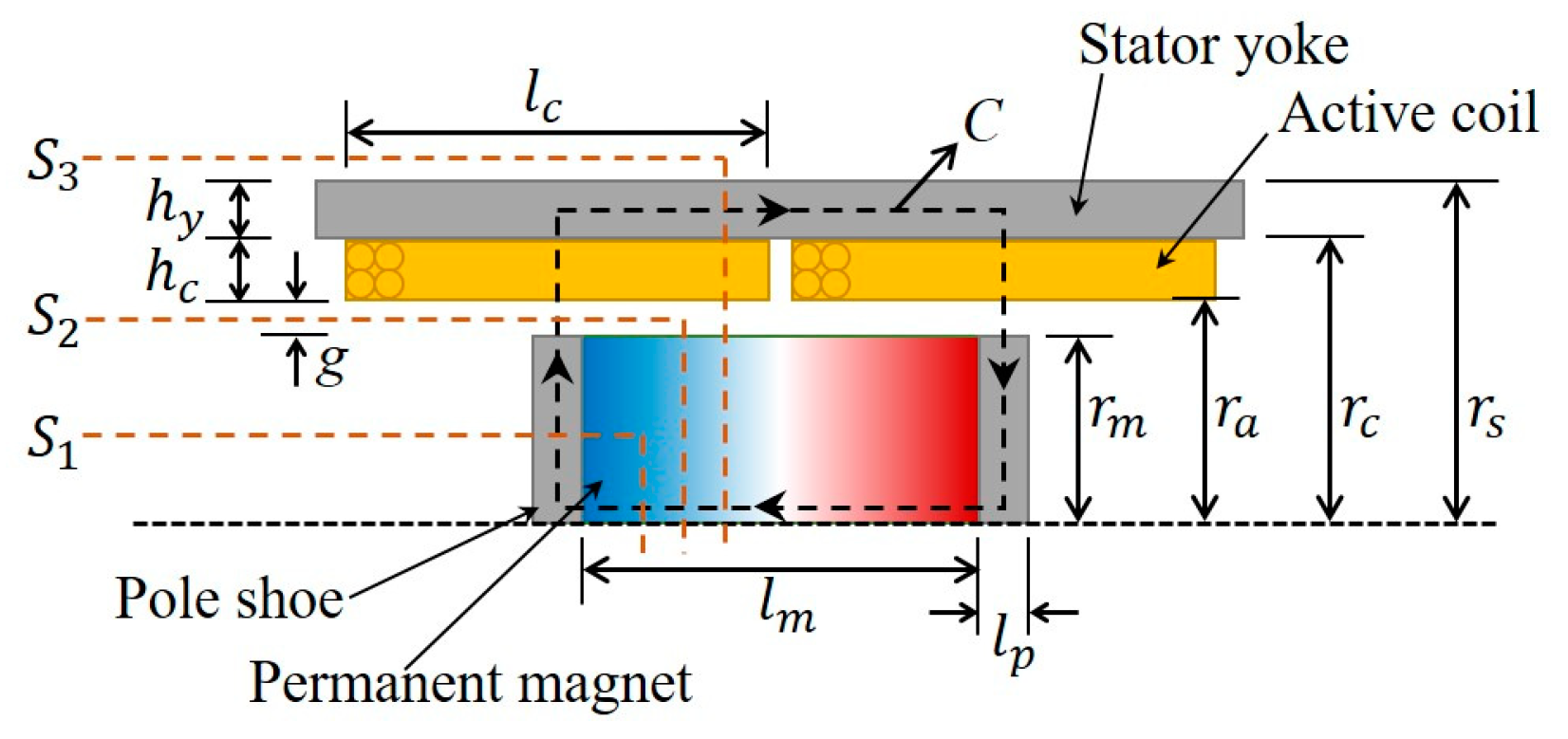
Figure 1. Cross-section of a coil-type electromagnetic damper.
Applsci 10 06078 g001
Figure 2. Schematics and photographs of the electromagnetic dampers: (a) coil type; (b) eddy-current type; (c) composite type.
Applsci 10 06078 g002
Figure 3. Experimental setup and measurement instruments: (a) damper fixed to the shaking table and load cell; (b) laser displacement meter.
Applsci 10 06078 g003
Figure 4. Hysteresis loops of electromagnetic dampers with an excitation amplitude of 12 mm: (a) displacement–force curve for the coil type; (b) displacement–force curve for the eddy-current type; (c) displacement–force curve for the composite type; (d) velocity–force curve for the coil type; (e) velocity–force curve for the eddy-current type; (f) velocity–force curve for the composite type.
Applsci 10 06078 g004
Figure 5. Hysteresis loops of electromagnetic dampers with an excitation frequency of 5 Hz: (a) displacement–force curve for the coil type; (b) displacement–force curve for the eddy-current type; (c) displacement–force curve for the composite type; (d) velocity–force curve for the coil type; (e) velocity–force curve for the eddy-current type; (f) velocity–force curve for the composite type.
Applsci 10 06078 g005
Figure 6. Maximum damping forces of the dampers under different excitation conditions: (a) amplitude–maximum force relationship for the coil type; (b) amplitude–maximum force relationship for the eddy-current type; (c) amplitude–maximum force relationship for the composite type; (d) frequency–maximum force relationship for the coil type; (e) frequency–maximum force relationship for the eddy-current type; (f) frequency–maximum force relationship for the composite type.
Applsci 10 06078 g006
Figure 7. Comparison of hysteresis curves: (a) excitation at an amplitude of 3 mm and a frequency of 1 Hz; (b) excitation at an amplitude of 3 mm and a frequency of 4 Hz; (c) excitation at an amplitude of 15 mm and a frequency of 4 Hz.
Applsci 10 06078 g007
Figure 8. Maximum damping forces of the dampers according to the excitation conditions: (a) changes in the excitation amplitude; (b) changes in the excitation frequency; (c) mesh plot for the excitation conditions.
Applsci 10 06078 g008
Figure 9. Regenerative hybrid electrodynamic damper (RHED) model: (a) damper shape; (b) finite element analysis model of the damper; (c) connected circuit.
Applsci 10 06078 g009
Figure 10. BH curve of the applied neodymium magnet.
Applsci 10 06078 g010
Figure 11. Magnetic flux density of the ferromagnetic pole pieces.
Applsci 10 06078 g011
Figure 12. Field results: (a) mesh configuration; (b) magnetic flux density; (c) magnetic flux lines; (d) current density.
Applsci 10 06078 g012
Figure 13. Changes in the driving force of the damper model over time.
Applsci 10 06078 g013
Figure 14. Changes in the electrical properties of the damper over time.
Applsci 10 06078 g014
Figure 15. Changes in the magnetic flux linkage and inductance of each winding: (a) flux linkage; (b) winding inductance.
Applsci 10 06078 g015
Figure 16. Hysteresis loops of the proposed damper: (a) position–force curve; (b) speed–force curve.
Applsci 10 06078 g016
Table 1. Main parameters of the damper.
NameSymbolDescription
Magnet length l m Actual length of the magnet (smaller than the pole pitch)
Pole shoe thickness l p Length excluding the magnetic length in the pole pitch
Coil length l c Axial length of each armature coil
Mover radius r m Outer radius of the magnet or pole pieces
Armature radius r a Inside radius of the armature
Winding radius r c Outside radius of the armature coil
Stator yoke radius r s Outside radius of the armature shell
Air gap g Distance between the mover and armature windings
Coil height h c Height of the armature coil section
Yoke thickness h y Armature shell thickness
Table 2. Values derived through optimization.
NameSymbolValueNameSymbolValue
Magnet length l m 0.06 mNumber of poles p 2
Pole shoe thickness l p 0.01 mWire diameter r w 0.009 m
Air gap g 0.001 mCoil turns N w 1400
Coil height h c 0.02 mCoil resistance R 27 Ω
Yoke thickness h y 0.02 m---
Table 3. Maximum damping forces (N) of the dampers according to the excitation conditions.
Type Freq.4 Hz 5 Hz 6 Hz 7 Hz Remarks
Amp.
Eddy current3 mm215.19234.14242.49240.66-
6 mm421.47458.95---
9 mm615.98669.36---
12 mm798.31826.67---
15 mm935.05---100%
Coil3 mm125.22136.64144.81145.25-
6 mm238.09264.73---
9 mm351.25390.60---
12 mm452.56496.52---
15 mm538.26---60%
Composite3 mm170.91182.43---
6 mm335.91367.56---
9 mm506.64550.21---
12 mm670.79729.11---
15 mm842.62---88%
Table 4. Properties of the non-linear permanent magnet.
CharacteristicsDescriptionValuesUnits
BrResidual induction1.35T
HcCoercivity−1,074,295.87A/m
BHmaxMaximum energy product36,2574.85J/m3