1. Introduction
Late in the last century, in order to meet the needs of deep-water gas and oil exploitation, subsea equipment suppliers began to develop and improve the all-electric subsea control technology [
1]. The all-electric Subsea Production Control System (AE), a leading-edge and breakthrough technology, which didn’t need hydraulic fluid and was driven completely by electric power, was proposed and developed [
2]. The key benefits of the AE system compared to the conventional Multiple Electric-Hydraulic Control System (MEH) are as follows [
3,
4,
5,
6,
7,
8,
9,
10]: the simplified system structure, enhanced control performance, improved system reliability and availability, increased the oil recovery factor and environmental friendliness. Furthermore, the advantages of AE system also include: the decreased power consumption [
11,
12], reduced Capital expenditure(CAPEX) and Operating expenditure(OPEX) [
13,
14,
15,
16], strengthened intelligence [
17,
18]. Therefore, with the improvement of key techniques of the AE system, the AE system will replace the MEH system as a trend in the future [
19,
20,
21].
The all-electric subsea gate valve actuator is one of the critical components of the AE system [
6,
7], which is used to open and close the production gate valve for the subsea Xmas tree. Its performance directly affects the reliability and safety of the AE system. Similar to the traditional hydraulic-driven subsea gate valve actuator, in the opening and closing processes of the valve, the all-electric subsea gate valve actuator is required to have a failsafe close ability, Remotely Operated Vehicle(ROV) override function, subsea ambient pressure compensation and valve position indication [
22,
23]. The all-electric subsea gate valve actuator uses the motor as the actuation unit, and the service life cycle of the motor is lower than that of the hydraulic cylinder. Therefore, to ensure the high reliability of the actuator, the actuation device should be designed with regard to redundancy [
24]. In addition, the subsea gate valve is a normally open valve. When the valve is opened, the power system needs to resist the resilience of the failsafe closing mechanism, which consumes a lot of energy in long term operation [
25]. Thus, to reduce the energy consumption, the low-power holding mechanism is required for the all-electric subsea gate valve actuator to ensure that the valve remains open with small power consumption.
The research and development of all-electric subsea gate valve actuators are in the early phase. A few oil companies like Cameron and FMC have carried out relevant research on it. Cameron’s all-electric subsea gate valve actuator realized the opening and closing operation of the subsea gate valve through a high-power “drive” motor, and was equipped with a low-power “clutch” motor to ensure that the valve remained open by means of a friction-based mechanism. Further, a closing spring was used as the failsafe close solution [
6,
7]. FMC’s all-electric subsea gate valve actuator powered the built-in motion control system via locally stored power from rechargeable batteries and capacitors to open and close the subsea gate valve and was equipped with the ROV interface. No springs were required to move a valve to a failsafe position [
8,
11]. At present, the all-electric subsea gate valves actuator of each oil company are still in the initial application stage, and the key technology of has not yet matured. Winther-Larssen [
26] developed a functional design specification for the all-electric subsea gate valve actuator and proposed a design for an all-electric subsea gate valve actuator, as well as the motor control system layout based on the specification. Jon Berven [
27] discussed failsafe solutions of the all-electric subsea gate valve actuator and created the calculation method of the peak load and the applied torque of the actuator. Wang [
24] proposed the multi-motor parallel redundant method to drive the valve and designed the structure of an all-electric subsea valve actuator. Xiao [
28] developed a subsea all-electric Christmas tree gate valve actuator and analyzed the sealing process of the gate valve. Liu [
25] proposed a new pressure compensation all-electric control gate valve and actuator integrated structure, which substantially reduced the high-pressure hydraulic resistance during valve closure.
According to the above analysis, it is obvious that some designs and researches have been done for the all-electric subsea gate valve actuator. However, most of the existing researches on the all-electric subsea gate valve actuator do not concentrate on the low-power holding mechanism, which was the unique composition of the all-electric subsea gate valve actuator. Therefore, a low-power holding mechanism of the all-electric subsea gate valve actuator is proposed in this paper, which uses an electromagnet as a driving element and combines spiral transmission and cam-like transmission, the corresponding mechanical and kinematic models are also established, respectively. The analytic expression of the relation is derived, respectively, for the lockable maximum load of the closing spring and the permissible stroke of the locking tab with regard to the design variables. The parameter effects and the corresponding sensitivities are analyzed as well. The lockable maximum load of the closing spring and the design parameters of the low-power holding mechanism are obtained.
This present work is aimed at developing a novel and feasible low-power holding mechanism of the all-electric subsea gate valve actuator, which can minimize the power consumption and cable number for control and improve the open-position keeping performance of an all-electric subsea gate valve actuator, only requiring a holding force of approximately 2%~7% of the maximum load of the closing spring to keep the valve open and with the ability to be applied to all-electric subsea gate valve actuators with various valve sizes and process pressure ratings, to bridge the gap of the low-power holding mechanism in the all-electric subsea gate valve actuator of the subsea production system.
The rest of the paper is organized as follows:
Section 2 briefly introduces the working process of the all-electric subsea gate valve actuator proposed, followed by a full presentation of the configuration, work principle and advantage of the proposed failsafe closing and low-power holding mechanism.
Section 3 presents the mechanical and kinematic models. In
Section 4, the detailed discussion of the parameter effects and sensitivity analysis is performed based on the established model and results. Finally, conclusions are given in
Section 5.
2. Research on the Configuration of Failsafe Closing and Low-Power Holding Mechanism
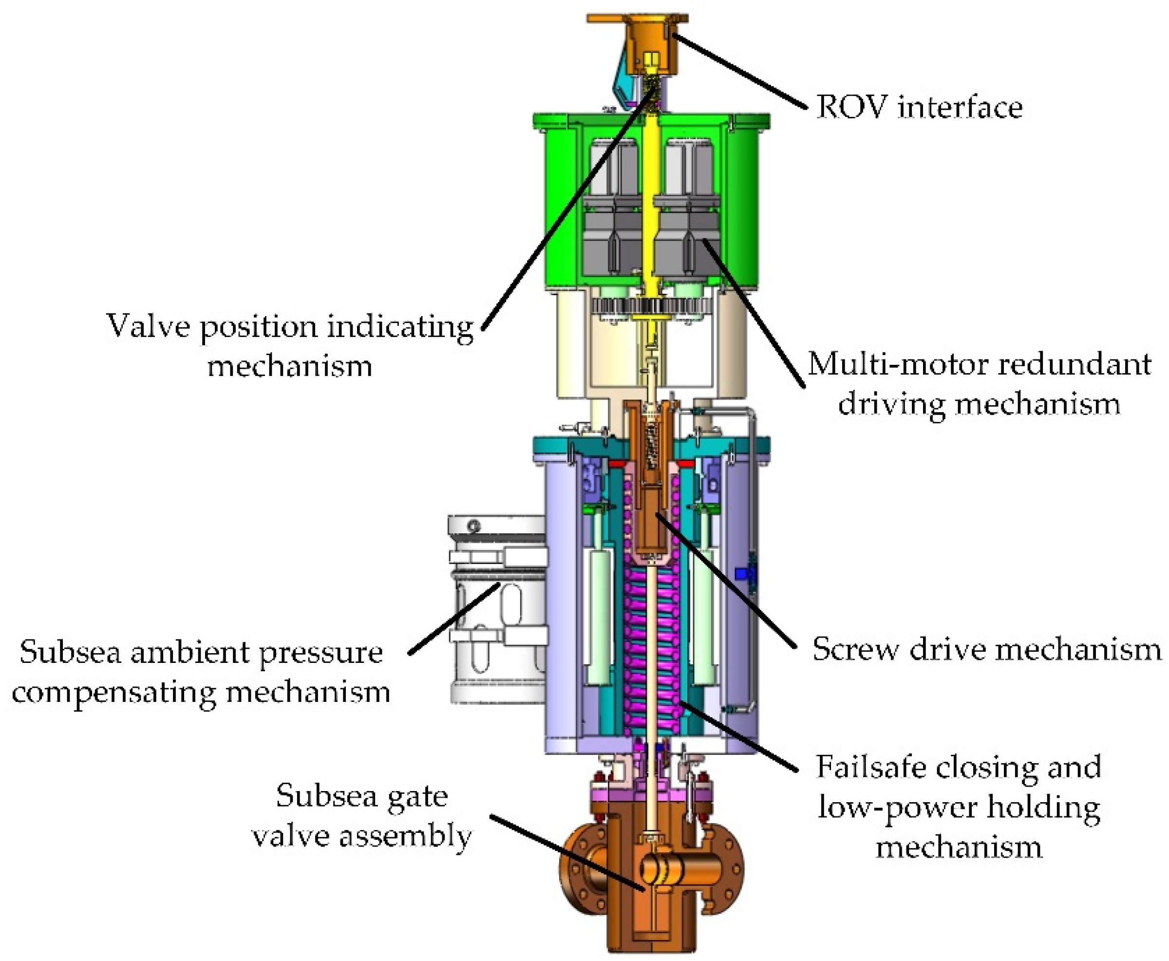
Based on the function of the all-electric subsea gate valve actuator, a configuration of the all-electric subsea gate valve actuator is proposed in this paper, as shown in
Figure 1, wherein the structure mainly includes the subsea gate valve assembly, failsafe closing and low-power holding mechanism, subsea ambient pressure compensating mechanism, screw drive mechanism, multi-motor redundant driving mechanism, valve position indicating mechanism and ROV interface. During the valve opening process, multi-motor redundant driving mechanism or ROV drives the valve stem and gate downward to open the subsea gate valve through the screw drive mechanism. After the subsea gate valve is fully opened, the low-power holding mechanism locks the failsafe closing mechanism to ensure that the valve remains open with the minimum power consumption. When the all-electric subsea production control system breaks down, the low-power holding mechanism and multi-motor redundant driving mechanism are power-off, the failsafe closing mechanism drives the valve stem and gate upward to realize the emergency failure close.
Failsafe closing mechanisms of the subsea valve include the mechanical failsafe closing mechanism and Uninterrupted Power System (UPS) failsafe closing mechanism [
29,
30]. As the service life cycle of the subsea Xmas tree or manifold is usually around 20 years, long term continuous power supply makes the UPS failsafe closing mechanism unpractical. The mechanical failsafe closing mechanism is most commonly used for this purpose. In the application of the mechanical failsafe closing mechanism for a subsea valve actuator, the spring-type configuration is reliable and widely used [
4,
25]. However, the force of the closing spring needs to be big enough to oppose the high-pressure fluid in the valve when a failure close occurs. So when the valve is opened, the power system needs to resist the large spring forces, which consume a lot of energy [
25]. Thus, the low-power holding mechanism also needed to be designed in the actuator of this paper. In addition, a single Electric Subsea Control Module (ESCM) is claimed to control up to 32 functional groups [
6]. However, a single ESCM can control up to 16 functional groups including sensors in an engineering application [
12], which puts forward requirements for the number of the actuator’s control cables.
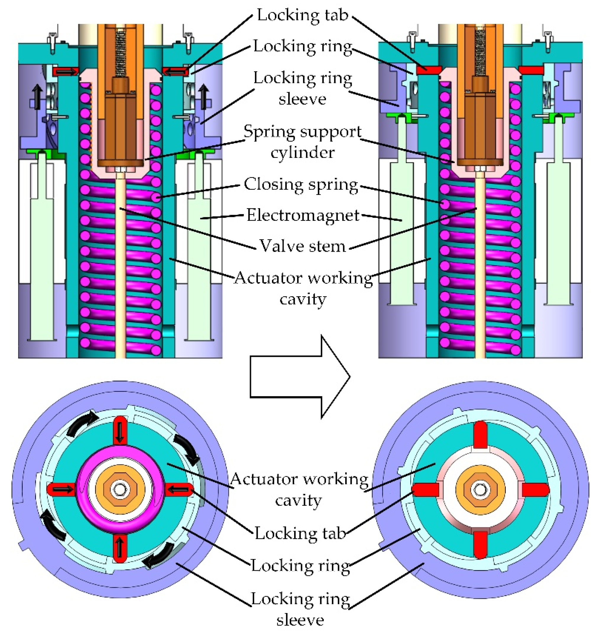
Based on the above analysis, the low-power holding mechanism is proposed in this paper, as shown in
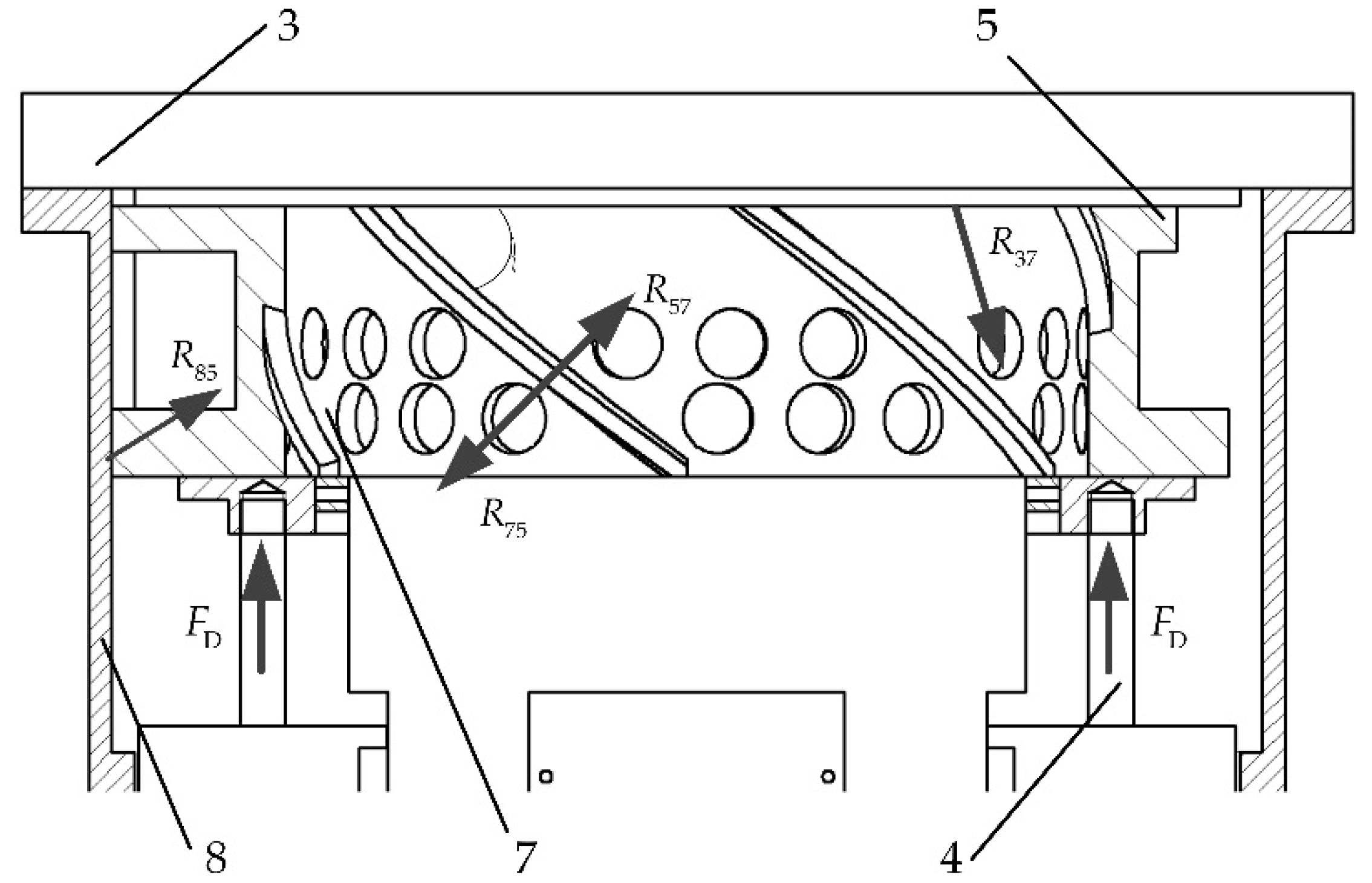
Figure 2, in which a spiral groove is machined inside the locking ring sleeve; a thread and four cam-like notches are machined outside the locking ring and inside the bottom, respectively. Four locking tabs are adopted due to the higher symmetry and stability of this configuration, compared with the design of two locking tabs. Furthermore, the requirements of this configuration for the size of the locking ring are moderate, because each locking tab needs a cam-like notch of the locking ring. The higher the number of locking tabs, the higher the number of cam-like notches necessary, which leads the size of the locking ring being easily unable to meet the requirements. Thus, the configuration of four locking tabs has advantages in realizing product function, improving product performance and meeting design constraints.
The locking and holding process of the low-power holding mechanism is shown in
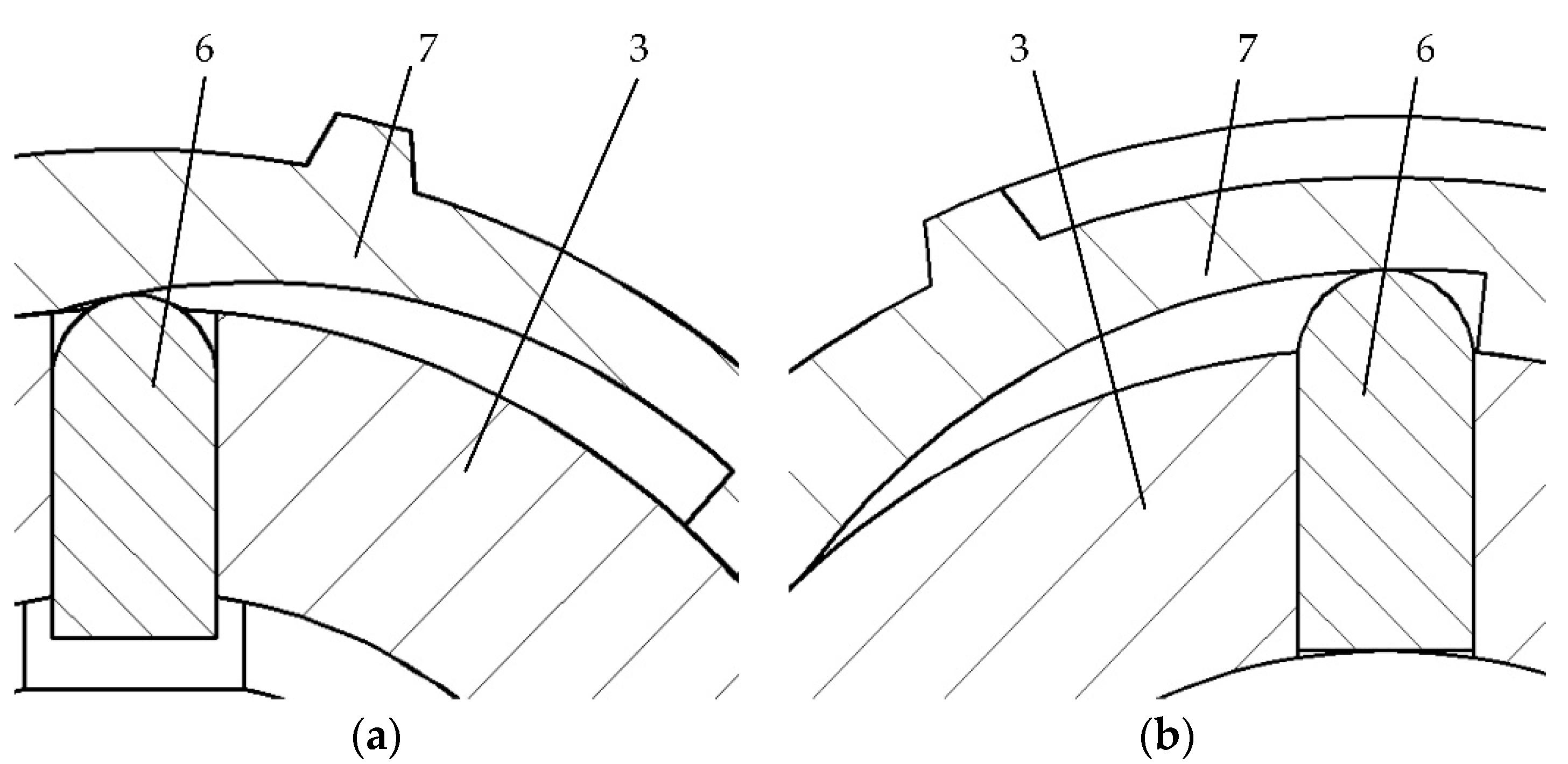
Figure 2. The driving mechanism pushes the spring support cylinder against the closing spring until the valve is fully opened, at which point the closing spring is at the limit, and the electromagnets are energized and push the locking ring sleeve upward. The locking ring sleeve drives the locking ring to rotate forward through the spiral groove. Meanwhile, the locking ring drives locking tabs to move inward through the cam-like notch. The locking process of the low-power holding mechanism is completed when the locking tabs fully enter the actuator working cavity and make contact with the slope of the spring support cylinder to block the cylinder moving back. After the locking process, the holding process of the low-power holding mechanism is started. In the holding process, the locking tab and the spring support cylinder constrain each other, and the position of the locking tab is restricted by the locking ring, to ensure that the valve remains open with the minimum power consumption.
When a valve fail-close occurs, the electromagnets are de-energized, thereby the position of the locking tab is not restricted by the locking ring. The unlocking process is opposite to the locking process, and the closing spring force is the driving force for the unlocking process. The closing spring drives the locking tabs to move outward through the slope of the spring support cylinder. Meanwhile, the locking tabs drive the locking ring to rotate backward through the cam-like notch surface, and the locking ring pushes the locking ring sleeve downward through the spiral groove. The unlocking process is completed when the locking tab and the spring support cylinder are separated. After the unlocking process, the closing spring continues to release rapidly and drives the spring support cylinder and the valve stem upward until the valve is fully closed.
The proposed low-power holding mechanism converts the axial force of the closing spring into the circumferential force by the spiral groove and the cam-like notches, which substantially reduces the output force required for the driving element of the low-power holding mechanism and increases the feasibility and reliability of the holding mechanism. In addition, different from the form of Cameron’s “clutch” motor, the proposed low-power holding mechanism is driven by the electromagnet, which effectively reduces the number of the actuator’s control cables.
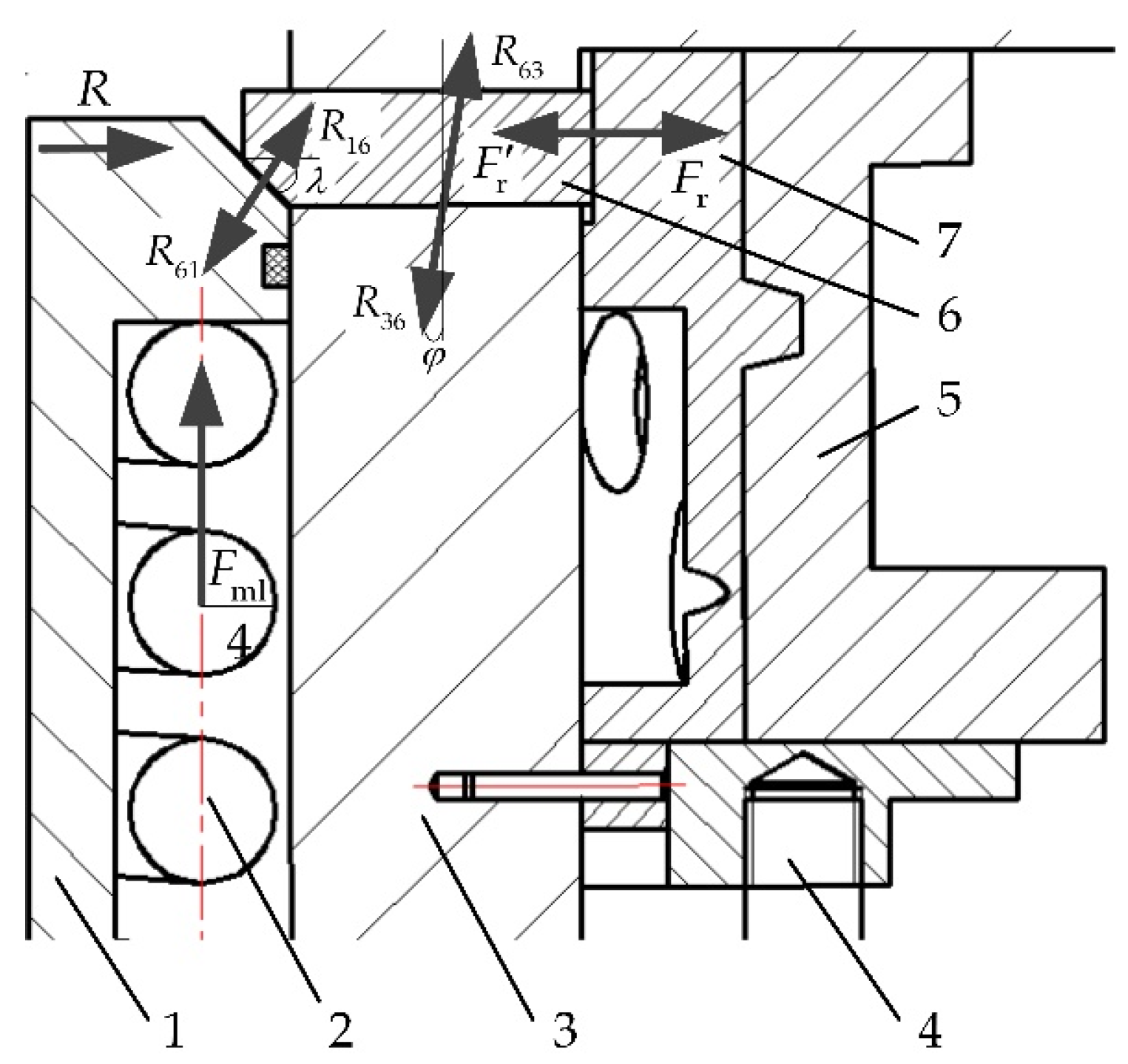
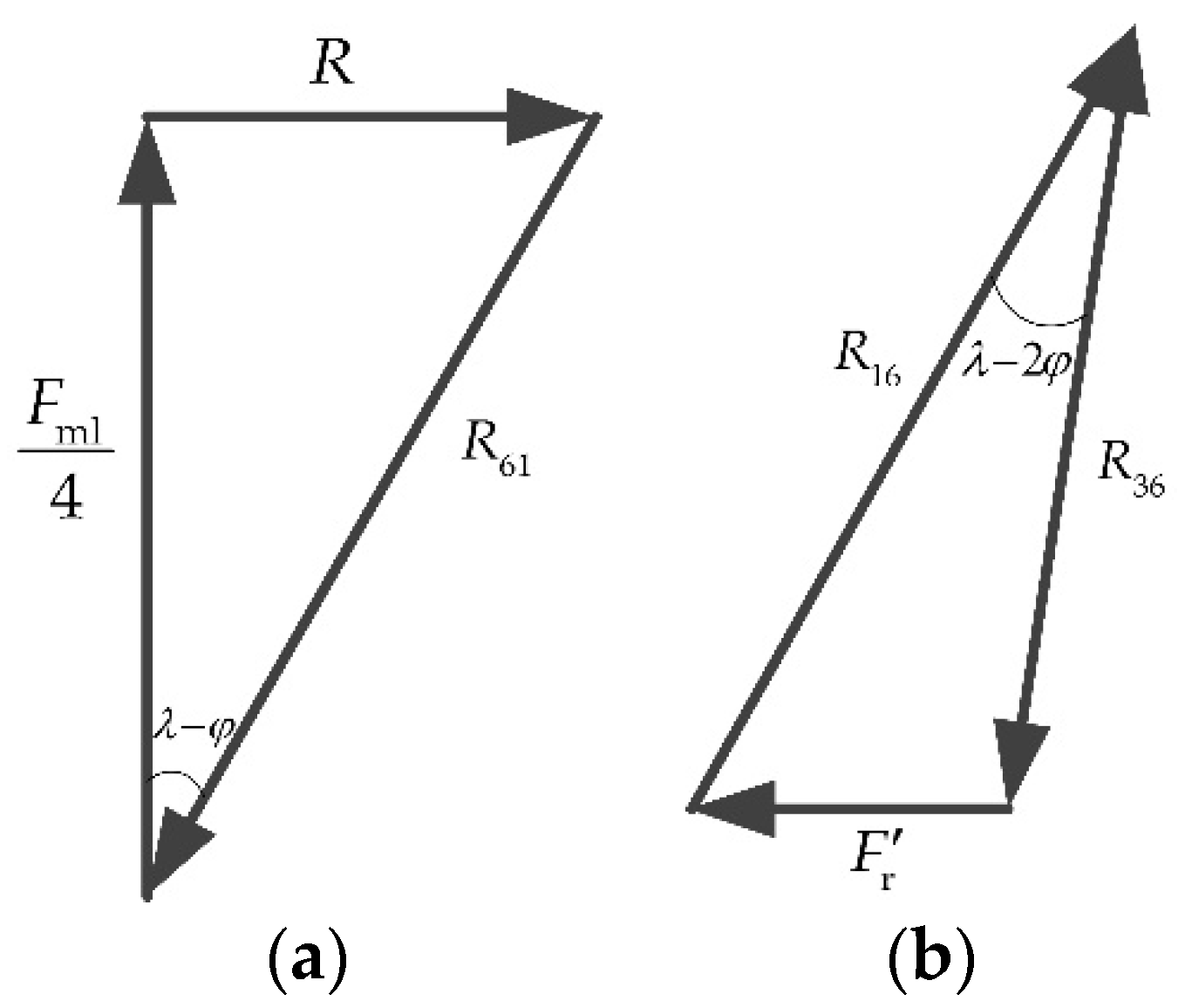
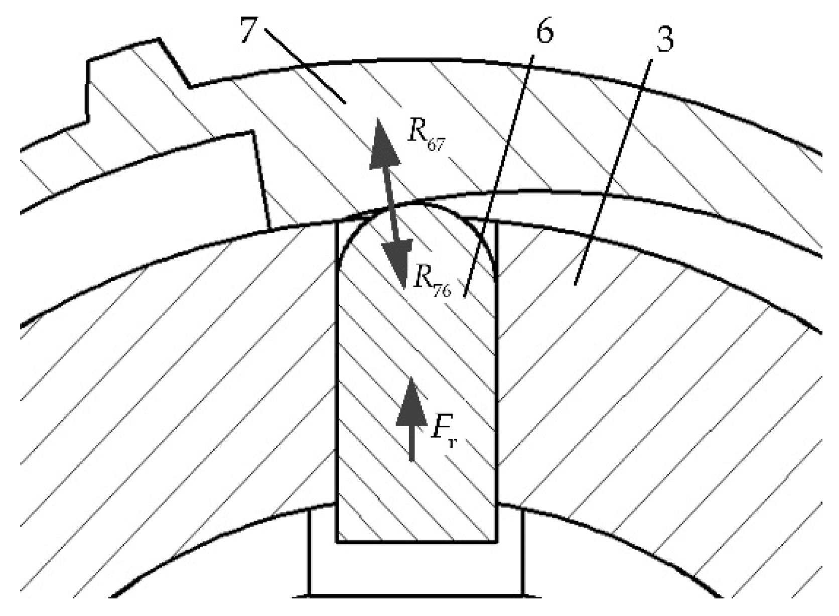
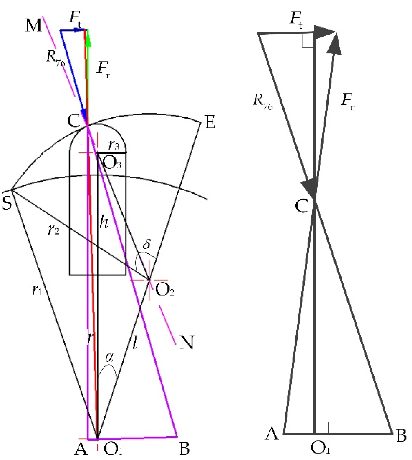
When a fail-close occurs, the maximum load produced by the high-pressure fluid which the all-electric subsea gate valve actuator can oppose depends on the force of the closing spring. According to the configuration of the low-power holding mechanism, the maximum load of the closing spring is related to the size of the low-power holding mechanism. However, the permissible stroke of the locking tab also depends on the size of the low-power holding mechanism and needs to be larger than the given working stroke, which will form a constraint for the optimization of the locking and holding ability of the low-power holding mechanism. Thus, it is necessary to analyze the mechanical and kinematic models of the low-power holding mechanism in detail.
5. Conclusions
To bridge the gap of the low-power holding mechanism in the all-electric subsea gate valve actuator of the subsea production system, minimize the power consumption and cable number for control and to improve the open-position keeping performance of all-electric subsea gate valve actuator, this paper proposed a novel low-power holding mechanism for the all-electric subsea gate valve actuator which can be applied to all-electric subsea gate valve actuators with various valve sizes and process pressure ratings. The paper also created mechanical and kinematic models, respectively, with regard to design variables, including the radius of the actuator working cavity r1, the radius of the notch of the locking ring r2, the radius of the locking tab r3, the center distance between the actuator working cavity and the locking ring notch l, and the radial deflection angle of the center of the locking ring notch α. Based on these analytic models, the variable effects on the lockable maximum load of the closing spring and the permissible stroke of the locking tab were analyzed. The parameter adjustment method was illustrated to satisfy the design criterion that the working stroke of the locking tab L should not exceed the permissible stroke of the locking tab [L]. The detailed conclusions are as follows:
The proposed low-power holding mechanism is driven by the electromagnet and combines spiral transmission and cam-like transmission to convert the axial force of the closing spring into circumferential force to minimize the output force required as well as the number of the actuator’s control cables, to improve the reliability and feasibility of the holding mechanism. The proposed low-power holding mechanism only requires a holding force of approximately 2%~7% of the maximum load of the closing spring to keep the valve open.
With a given output force of the electromagnet, the lockable maximum load the low-power holding mechanism can be increased by increasing r2 or decreasing r3, l and α. In the design space, the variable sensitivities of the lockable maximum load increases with the increase in r2 or the decrease in r3, l and α; the lockable maximum load is most sensitive to l and after that come α, r2 and r3 with regard to the average sensitivities in the design space.
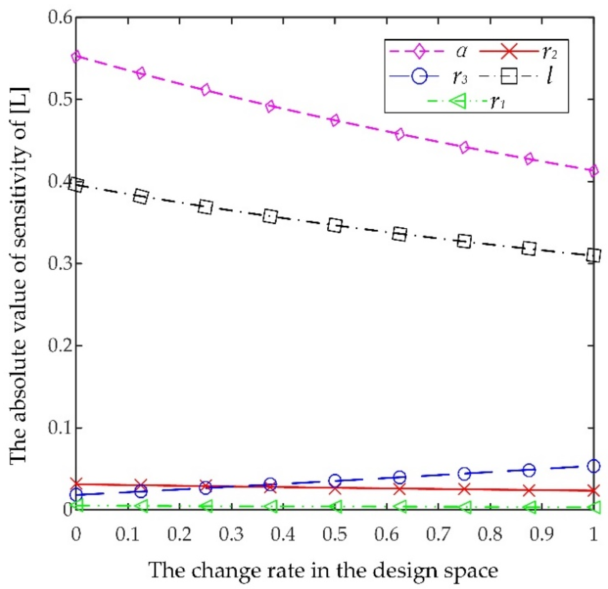
The permissible stroke of the locking tab increases with the increase in r1, l and α or the decrease in r2 and r3. In the design space, the variable sensitivities of the permissible stroke increase with the increase in r3 or the decrease in r2, l and α; the sensitivity of the permissible stroke to r1 remains on the lowest level in the full range; with regard to the average sensitivities of the permissible stroke, the most sensitive variable is α and after that l, r3, r2 and r1.
The design criterion is that the working stroke of the locking tab L should not exceed the permissible stroke of the locking tab [L]. The parameters can be adjusted to satisfy the criterion considering the variable sensitivities meanwhile minimizing the effect on the lockable maximum load. In the given case, the final parameter set of the low-power holding mechanism is: r1 = 150 mm, r2 = 150 mm, r3 = 10 mm, l = 30 mm and α = 39.31°, with a lockable maximum load of the closing spring of 71.44 kN.
Further research will focus on the analysis of the influence of contact deformation and surface morphology on the modeling and the open-position keeping performance of the low-power holding mechanism. In addition, the future scope of the work can be directed toward the reliability assessment of the all-electric subsea gate valve actuator considering the subsea environment and the production fluid factors to ensure the long term application of the actuator in the subsea environment. The procedure in the paper can be applied to the design and research of other key components of the all-electric subsea production control system, such as the all-electric subsea ball valve actuator, which is required for the failsafe close ability and the open-position keeping function.

 ,
, 


