1. Introduction
Up to the present, much attention has been given to fiber comb filters, which manipulate optical signals routed in optical systems, due to their structural simplicity, good fiber compatibility, and great facility to fabricate. They have been utilized for the implementation of optical pulse train generation [
1], multiwavelength switching or lasing [
2,
3,
4,
5], optical label switching [
6,
7], and microwave signal processing [
8,
9,
10]. Flexible adjustment of the wavelength (or frequency) location of the transmission bands of a comb filter is a crucial function to pass or reject the desired wavelength component in wavelength-division-multiplexing-based optical communication systems. While continuous wavelength tunability has been realized in numerous comb filters based on a Sagnac birefringence loop [
11,
12], a Lyot-type birefringence interferometer [
13,
14], and a Mach–Zehnder interferometer (MZI) [
15,
16], a comb filter incorporating a polarization–diversity loop structure (PDLS) [
17,
18,
19,
20] offers the most effective and diverse wavelength controllability (including wavelength switching and tuning) in comparison with conventional comb filters. PDLS-based comb filters are also more robust to external physical perturbations, such as ambient temperature and pressure changes, than MZI-based comb filters [
15,
16]. Over the last three years, several studies have been conducted for realization of continuous wavelength tunability in periodic comb spectra of PDLS-based fiber comb filters [
21,
22,
23,
24]. A continuously wavelength-tunable PDLS-based zeroth-order comb filter employing one birefringent component, i.e., a high-birefringence fiber (HBF) segment, was proposed by using three ordered wave retarder combinations (WRC’s): Two quarter-wave retarders (QWR’s), an ordered WRC of a QWR and a half-wave retarder (HWR), and another ordered WRC of an HWR and a QWR [
21]. In addition to the zeroth-order comb filters, there have been series of reports on the continuous control of the wavelength location of passband-flattened and -narrowed transmission spectra, which could be obtained in a PDLS-based first-order comb filter with two HBF segments [
22,
23,
24]. In terms of these first-order wavelength-tunable comb filters, an ordered WRC of an HWR and a QWR was positioned before each of two HBF segments. By controlling the azimuth orientation angles (AOA’s) of the wave retarders comprising the above comb filters, an incremental phase delay (
ψ) of 0°–360° can be introduced into the transmittance function of each filter. In these previous works on the first-order comb filters [
22,
23,
24], only the ordered WRC of an HWR and a QWR was employed and placed before each HBF segment for implementation of the continuous modulation of the extra phase delay
ψ in the filter transmittance function. Another ordered WRC of a QWR and an HWR may also be a candidate to achieve the continuous
ψ modulation. To the best of our knowledge, the continuous wavelength tuning of passband-narrowed transmission spectra was not accomplished by using an ordered WRC of a QWR and an HWR in the PDLS-based first-order comb filter. The introduction of the new ordered WRC will lead to completely different AOA sets of the wave retarders, required for the continuous frequency tuning of the filter spectrum. In particular, recent previous works failed to implement the continuous wavelength tuning of passband-narrowed transmission spectra [
22] or utilized an additional HWR to increase the visibility of passband-narrowed transmission spectra leading to the use of five wave retarders for the desired wavelength-tuning operation [
23,
24]. Here, we theoretically and experimentally demonstrate a narrowband fiber comb filter capable of continuously tuning its wavelength position with a composite combination of wave retarders in the PDLS. The demonstrated PDLS-based filter consists of a polarizing beam splitter (PBS), two HBF segments of equal length, an ordered WRC of a QWR and an HWR before the first HBF segment, and an ordered WRC of an HWR and a QWR ahead of the second HBF segment. The second HBF segment is butt-coupled to one port of the PBS so that its slow axis should be oriented at 22.5° with respect to the horizontal axis of the PBS, which enables the maximum spectral visibility without the use of an additional HWR. As described in
Section 2, considering the filter transmittance obtained by Jones calculus, we found the AOA sets of the four wave retarders, which could bring extra phase shifts (
ψ’s) from 0° to 360° to the narrowband transmittance function. From filter transmission spectra calculated according to the AOA sets found above, it is confirmed that the narrowband comb spectrum can be continuously frequency-tuned by properly adjusting the AOA’s, clearly demonstrating the continuous wavelength tunability of the proposed comb filter adopting composite WRC’s. As can be found in
Section 3, this theoretical prediction is verified by experimental demonstration showing eight measured narrowband transmission spectra spaced 0.1 nm apart in wavelength. Finally, a brief summary and conclusion on our continuously wavelength-tunable narrowband comb filter are given in
Section 4.
2. Principle of Operation
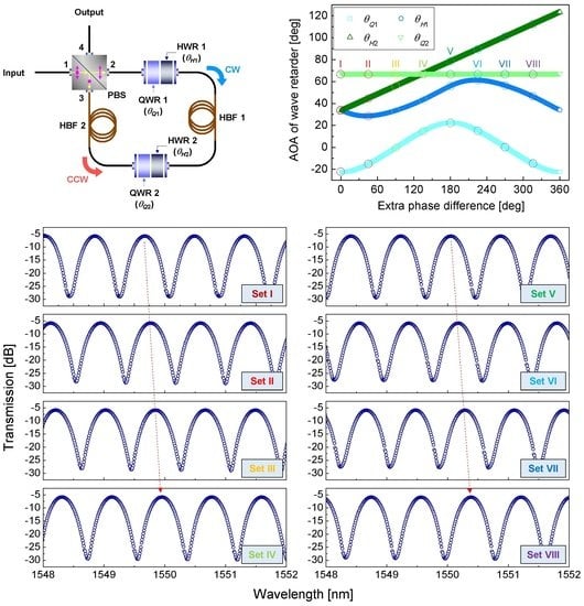
Figure 1a shows a schematic diagram of the proposed filter composed of a PBS, two HBF segments of the same length, an ordered WRC of a QWR and an HWR (designated as QWR 1 and HWR 1, respectively) before the first HBF segment depicted as HBF 1, and an ordered WRC of an HWR and a QWR (designated as HWR 2 and QWR 2, respectively) in front of the second HBF segment depicted as HBF 2. HBF 2 is butt-coupled to port 3 of the PBS so that its slow axis should be oriented at 22.5° with respect to the horizontal axis of the PBS. This butt-coupling between HBF 2 and the PBS maximizes the extinction ratio of the narrowband comb spectrum of the filter. Each ordered WRC can modify the effective phase delay difference between the fast and slow axes of HBF 1 or HBF 2. A change in this effective phase difference indicates a change in the effective birefringence of the entire polarization–diversity loop, which results in a wavelength shift of the transmission spectrum in the PDLS-based comb filter. In particular, the second WRC composed of HWR 2 and QWR 2 also functions as an effective rotator of HBF 2, which can adjust the effective angular difference between the two principal axes of HBF 1 and HBF 2. Input light incident on port 1 of the PBS is decomposed into linear horizontal polarization (LHP) and linear vertical polarization (LVP) components, which circulate through the polarization–diversity loop of the filter in the clockwise (CW) and counterclockwise (CCW) directions, respectively. If two orthogonally polarized modes propagating along the fast and slow axes of the HBF encounter with each other, having the same state of polarization (SOP) through some polarization conversion components (like wave retarders or polarizers), these orthogonal modes can interfere with the phase delay difference Γ resulting in a periodic interference spectrum. The periodic comb spectrum of our filter is based on this polarization interference defined by Γ = 2
πBL/
λ, where
B,
L, and
λ are the HBF birefringence, HBF length, and wavelength in vacuum, respectively. Engineered selection of the AOA’s of the wave retarders located before the HBF can create an additional phase difference
ψ, resulting in a total phase difference of Γ +
ψ. A monotonous change in
ψ gives a monotonous wavelength shift in the interference comb spectrum.
As can be found from
Figure 1a, the LHP and LVP components emerging from ports 2 and 3 of the PBS are guided in CW and CCW directions, respectively. Here we assume the horizontal and vertical axes of the PBS as
x and
y axes, respectively, and the direction of light propagation as the
z axis for convenience. As seen in
Figure 1b, linear horizontally polarized light from port 2 of the PBS goes through a linear horizontal polarizer (i.e.,
x-axis polarizer), QWR 1 (with its slow axis oriented at
θQ1 with respect to the
x axis), HWR 1 (oriented at
θH1), HBF 1 (oriented at
θB1), HWR 2 (oriented at
θH2), QWR 2 (oriented at
θQ2), HBF 2 (oriented at
θB2), and a linear horizontal analyzer (i.e.,
x-axis polarizer) in turn along the CW path. In a similar way, linear vertically polarized light from port 3 of the PBS passes through a linear vertical polarizer (i.e.,
y-axis polarizer), HBF 2 (−
θB2 oriented), QWR 2 (−
θQ2 oriented), HWR 2 (−
θH2 oriented), HBF 1 (−
θB1 oriented), HWR 1 (−
θH1 oriented), QWR 1 (−
θQ1 oriented), and a linear vertical analyzer (i.e.,
y-axis polarizer) in sequence along the CCW path. F and S appearing on the wave retarders and the HBF’s denote their fast and slow axes, respectively. Two orthogonally polarized light (i.e., LHP and LVP components) circulates in the polarization–diversity loop along the CW and CCW paths, respectively. In each path, polarization interference occurs owing to Γ of each HBF, leading to an interference spectrum. Because the input optical power of the filter is distributed to ports 2 and 3 of the PBS according to its input SOP, the insertion losses of these two interference spectra (for the CW and CCW paths) also rely on the input SOP. However, there is no difference in other spectral characteristics of the two interference spectra, for example, a free spectral range (FSR) that determines a channel spacing of the comb filter [
17]. This is because the Jones transfer matrices of all the wave retarders and HBF’s used here are lossless and unitary, which can also be confirmed in the following Jones matrix formulation of the filter transmittance. Owing to the orthogonality of the SOP’s of these two interference spectra, the output transmission spectrum of the filter can be obtained by simple arithmetic sum of them. Moreover, as any two orthogonal polarization bases (e.g., LHP and LVP) can generate an arbitrary SOP, the output spectrum is independent of input polarization in our filter [
17].
A comb spectrum created by polarization interference has a sinusoidal transmittance function of Γ. As a simple example, the transmittance function of a polarization interference spectrum created in an HBF segment sandwiched by two linear polarizers is represented by
p +
qcosΓ (where
p and
q are real constants) called the zeroth-order transmittance function. If the number of the HBF segments inserted between linear polarizers becomes the integer
M (≥2), this transmittance function is called the (
M−1)-order transmittance function, which includes sinusoidal functions of Γ, such as cos
MΓ, cos
M−1Γ, and cosΓ [
25]. To continuously tune the wavelength of a higher-order transmittance function, an extra phase retardation difference
ψ should be added to the phase retardation difference Γ of each HBF segment. For this, in view of the transmittance function, (Γ +
ψ) should be substituted for Γ in the sinusoidal functions (cos
MΓ, cos
M−1Γ, etc.). As we want to tune a narrowband comb spectrum of the first-order transmittance function (
M = 2), the effective phase retardation difference of each HBF segment between linear polarizers needs to become (Γ +
ψ) while the effective slow-axis AOA’s of HBF 1 and HBF 2 are set as 22.5° and 67.5°, respectively, as can be found in the CW path of
Figure 1c. These two effective AOA’s are inferred by analyzing the AOA relationship between birefringent components in a conventional fan Solc filter with a narrowband transmittance [
26]. The extra phase difference
ψ and AOA’s (
θB1 and
θB2) of HBF can be effectively modified by changing the input polarization of HBF 1 or HBF 2. This input SOP of each HBF can be determined by controlling the AOA’s of the four wave retarders (QWR 1, HWR 1, HWR 2, and QWR 2). If we can set
ψ to increase from 0° to 360° through the AOA adjustment of the wave retarders, the narrowband comb spectrum can be continuously red-shifted by a wavelength displacement corresponding to one FSR.
The general transmittance
tfilter of our filter can be derived using the Jones transfer matrix
T, which contains the transfer matrices of two QWR’s, two HWR’s, two HBF’s, and two polarizers, obtained along the CW and CCW paths, the first and second terms of the right side of (1), respectively. It is assumed here that there is no insertion loss in all the optical components and the wave retarders are frequency-independent.
where
TQWR1,
THWR1,
THBF1,
THWR2,
TQWR2, and
THBF2 are the Jones transfer matrices of QWR 1, HWR 1, HBF 1, HWR 2, QWR 2, and HBF 2, which have the slow-axis AOA’s of
θQ1,
θH1,
θB1,
θH2,
θQ2, and
θB2 with respect to the
x axis, respectively. The Jones transfer matrices (
TQWR,
THWR, and
THBF) of a QWR, an HWR, and an HBF, which have the AOA’s of
θQ,
θH, and
θB, respectively, are given as follows.
and
On the basis of (1),
tfilter is given by
where
α =
θQ1 –
θQ2,
β = 2
θH1 – 2
θH2 –
θQ1 +
θQ2,
γ =
θQ1 +
θQ2, and
δ = 2
θH1 + 2
θH2 –
θQ1 –
θQ2. The narrowband transmittance function
tnarrow can be obtained from this general transmittance
tfilter and is given by (5), which can also be drawn out in consideration of the transmittance function of a conventional fan Solc filter with two birefringent components (
M = 2) [
22]. The additional phase difference
ψ in
tnarrow sets the wavelength position of the narrowband transmission spectrum, that is, can be utilized to tune the spectral location.
To establish the theoretical conditions of the wave retarders, required to continuously tune the wavelength location of
tnarrow, the AOA’s of the four wave retarders, or (
θQ1,
θH1,
θH2,
θQ2), which could induce
ψ’s ranging from 0° to 360° in
tnarrow, were investigated by quantitatively comparing (3) with (5).
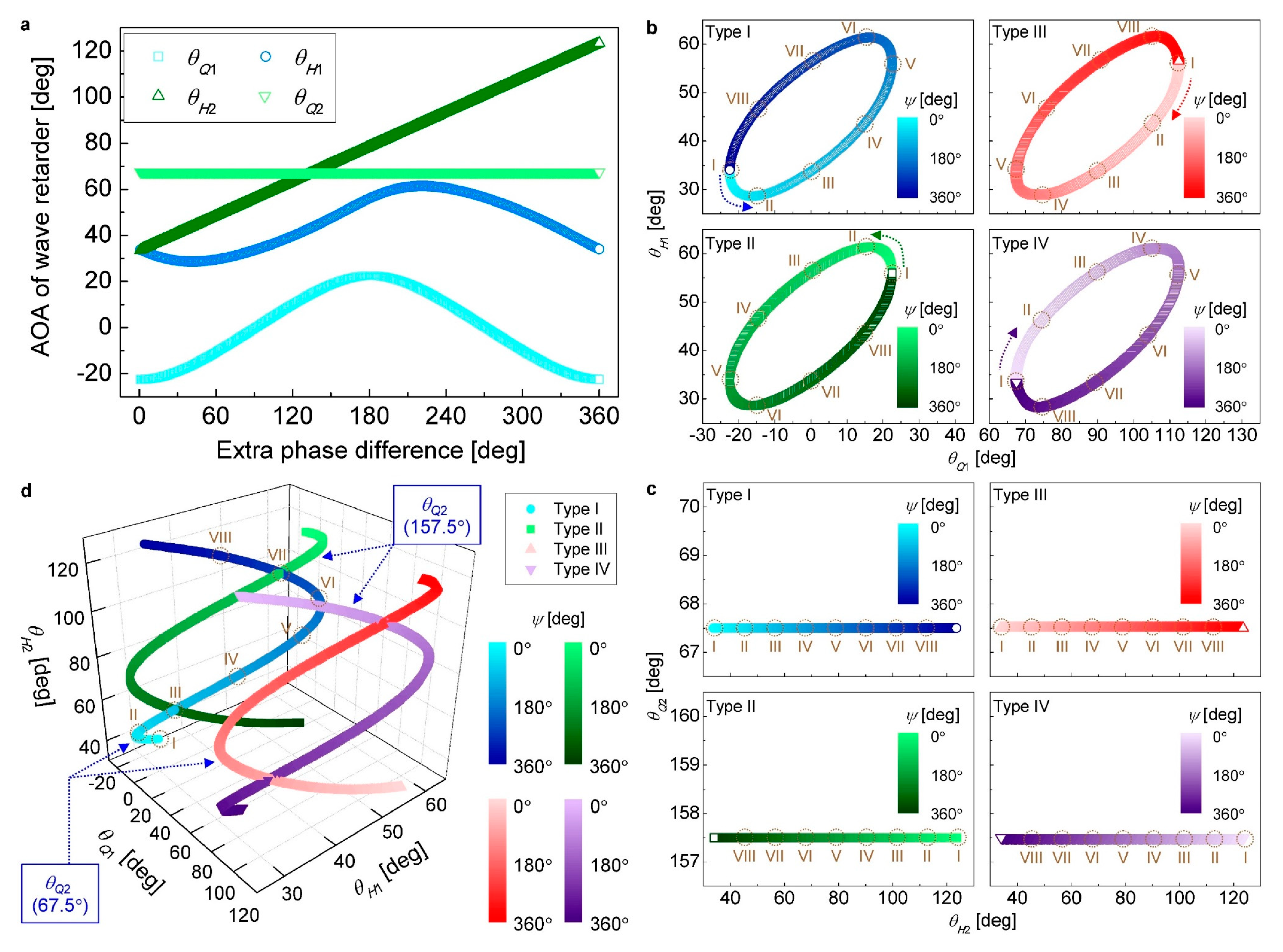
Figure 2a shows the AOA sets of four wave retarders (
θQ1,
θH1,
θH2,
θQ2), referred hereafter to as four AOA (FAOA) sets, indicated by skyblue squares, blue circles, olive triangles, and green inverted triangles, respectively, for the extra phase difference
ψ (from 0° to 360° with a step of 1°), which are found for the continuous wavelength tuning of
tnarrow in (5) at
θB1 = 0°. As
ψ increases,
θQ1 and
θH1 alternate with
ψ at the same frequency, and they are bounded in −22.5° <
θQ1 < 22.5° and 28.6° <
θH1 < 61.4°.
θQ1(
ψ) and
θH1(
ψ) seem to have similar alternating trajectories, but they are not sinusoidal functions of
ψ. On the other hand,
θH2 linearly increases with
ψ in an AOA range of 33.4° <
θH2 < 123.5°, and
θQ2 is not a function of
ψ but a constant value of 67.5°. From
Figure 2a, we can clearly see that an FAOA set (
θQ1,
θH1,
θH2,
θQ2) corresponds to any
ψ increasing from 0° to 360° with a step of 1°. This means that the narrowband transmittance
tnarrow can be wavelength-tuned if an FAOA set is picked along these four trajectories of
θQ1(
ψ),
θH1(
ψ),
θH2(
ψ), and
θQ2(
ψ) so that
ψ increases from 0° to 360°. Moreover, it can effortlessly be confirmed from quantitative calculations that the same locus is obtained for each trajectory shown in
Figure 2a, even for
ψ with 360 or more steps split at an angle smaller than 1°, which proves once again the continuous frequency tunability of
tnarrow in our filter. In the case of
θB1 ≠ 0°,
θH1 and
θH2 are simultaneously increased by
θB1/2 for all
ψ.
Figure 2b,c show four types of loci of (
θQ1,
θH1) and (
θH2,
θQ2), which are plotted for
ψ (from 0° to 360°) at
θB1 = 0° in the Cartesian coordinate systems of (
θQ1,
θH1) and (
θH2,
θQ2), respectively. There are four types of FAOA sets that can implement the continuous frequency tuning of the narrowband spectrum, and the AOA sets represented in
Figure 2a show one of them. In
Figure 2b, four subplots displayed as Types I to IV, that is, the four loci of (
θQ1,
θH1), show Lissajous trajectories plotted using both
θQ1(
ψ) and
θH1(
ψ) in these four types of FAOA sets. Similarly, in
Figure 2c, four subplots denoted by Types I to IV, i.e., the four loci of (
θH2,
θQ2), are obtained using both
θH2(
ψ) and
θQ2(
ψ) in the four types of FAOA sets. In
Figure 2b,c, the locus plots of Types I to IV are indicated by blue circles, green squares, red triangles, and violet inverted triangles, respectively. Among the four types of loci, two Type I loci in
Figure 2b,c are drawn out from
θQ1(
ψ) and
θH1(
ψ) traces and
θH2(
ψ) and
θQ2(
ψ) traces in
Figure 2a, respectively. In terms of Types I and II loci in
Figure 2b, the point of (
θQ1,
θH1) on the elliptical locus moves CCW along the locus, starting at a void circle and a void square, respectively, while
ψ increases from 0° to 360°. As opposed to the former case, in the case of Types III and IV loci in
Figure 2b, the point of (
θQ1,
θH1) moves CW along the locus, starting at a void triangle and a void inverted triangle, respectively, with increasing
ψ from 0° to 360°. In particular, the elliptical locus of Type I is determined by the following relations (6) and (7), which can be derived by considering the
ψ-driven evolution of the output SOP of HWR 1 on the Poincare sphere [
22].
and
These simple and deterministic locus patterns pave the way for easy prediction of FAOA sets for the continuous wavelength tuning of narrowband spectra. For Types I and III loci in
Figure 2c, the point of AOA’s (
θH2,
θQ2) on the linear locus goes from left to right with
θQ2 maintained as 67.5°, as
ψ increases from 0° to 360°. On the contrary, for Types II and IV loci in
Figure 2c, the point of (
θH2,
θQ2) on the locus shifts from right to left keeping
θQ2 = 157.5° with the increase of
ψ from 0° to 360°. To grasp the total loci at a glance, as shown in
Figure 2d, we plotted the four loci of (
θQ1,
θH1,
θH2) with respect to
ψ (from 0° to 360°) at
θB1 = 0° in the Cartesian coordinate system of
θQ1,
θH1, and
θH2, using
θQ1(
ψ),
θH1(
ψ), and
θH2(
ψ) shown in
Figure 2a. To maintain consistency, the locus plots of Types I to IV are indicated by blue circles, green squares, red triangles, and violet inverted triangles, respectively, as in
Figure 2b,c. In terms of Types I and III loci (
θQ2 = 67.5°), the point of AOA’s (
θQ1,
θH1,
θH2) on these helical loci rises from the bottom with the increase of
ψ (from bright to dark markers). In contrast, for Types II and IV loci (
θQ2 = 157.5°), the point of (
θQ1,
θH1,
θH2) on the loci comes down from the top with increasing
ψ. For each type of locus, eight points indicated by I to VIII show the eight sets of FAOA’s selected to spectrally shift
tnarrow. From set I to set VIII, an additional phase difference
ψ increases from 0° to 315° with a step of 45°. In other words, if we put the FSR of the narrowband transmission spectrum as Δ
λ, the narrowband transmission spectrum at set I is red-shifted by Δ
λ/8, Δ
λ/4, 3Δ
λ/8, Δ
λ/2, 5Δ
λ/8, 3Δ
λ/4, and 7Δ
λ/8 at sets II to VIII, respectively.
3. Spectral Calculation and Experimental Demonstration
Figure 3 shows the calculated narrowband transmission spectra of the proposed filter, obtained at the eight selected FAOA sets (sets I to VIII) over the wavelength range from 1548 to 1552 nm. In this spectrum calculation, the length
L and birefringence
B of each HBF (HBF 1 or HBF 2) were set as 7.2 m and 4.166 × 10
−4 to make Δ
λ of the narrowband spectrum become ~0.8 nm at 1550 nm, respectively. As can be checked from the figure, the narrowband spectrum moves towards a longer wavelength region as the FAOA set changes from set I to set VIII. If one peak wavelength of the comb spectrum at set I is denoted by
λ0 (=1550.4 nm), as shown in the left-top subplot of
Figure 3,
λ0 increases from 1550.5 to 1551.1 nm by 0.1 nm per set, while the FAOA set switches from set II to set VIII. In particular, it was also confirmed through additional spectral calculations that
λ0 linearly increased with
ψ for finer values of
ψ (for instance, 360 values of
ψ starting from 0° with a step of 1°), although the calculation results were not provided here. This implies that the narrowband comb spectrum can be continuously tuned in its wavelength. As a result, this calculated result corroborates that our comb filter can be continuously frequency-tuned within Δ
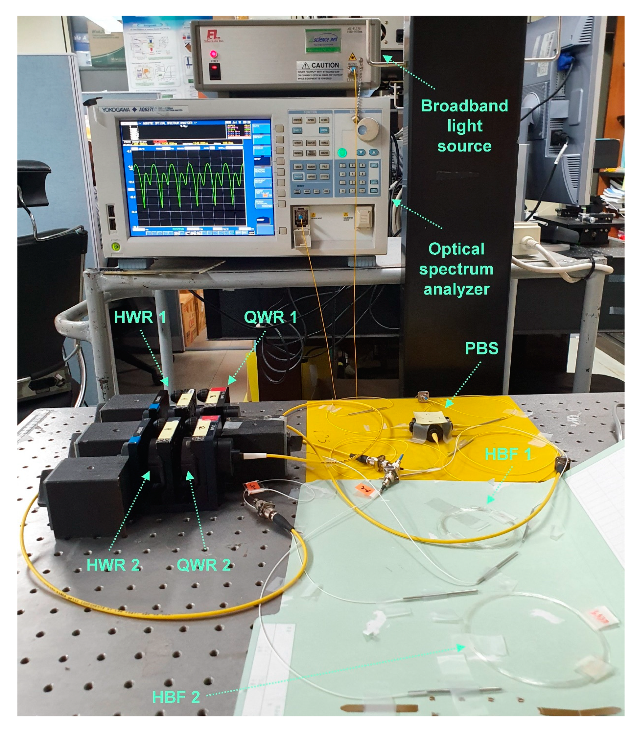
λ by properly selecting FAOA sets. For experimental demonstration of the calculated results, an actual implementation of our filter was done by incorporating a PBS (OZ Optics) pigtailed with single-mode fiber (SMF), two SMF-pigtailed QWR’s (OZ Optics), two SMF-pigtailed HWR’s (OZ Optics), and two equal-length bow-tie HBF segments (Fibercore), as shown in
Figure 1. Considering the birefringence (~4.166 × 10
−4) of the HBF, its length was tailored to be ~7.12 m so that Δ
λ became ~0.8 nm at 1550 nm. The transmission spectra of the constructed filter were measured using a broadband light source (Fiberlabs FL7701) and an optical spectrum analyzer (Yokogawa AQ6370C).
Figure 4 shows an actual experimental setup for measurement of the transmission spectra of the filter. As shown in
Figure 4, the input and output ports (ports 1 and 4) of the filter were connected to the broadband light source and optical spectrum analyzer, respectively, with FC/PC type fiber patchcords. The sensitivity and resolution bandwidth of the optical spectrum analyzer were set as HIGH1 and 0.02 nm, respectively, to acquire high resolution and high contrast optical spectra. To avoid unwanted displacements of all the optical components of the filter, we taped them up on the optical table so that they were immobilized during the spectrum measurement.
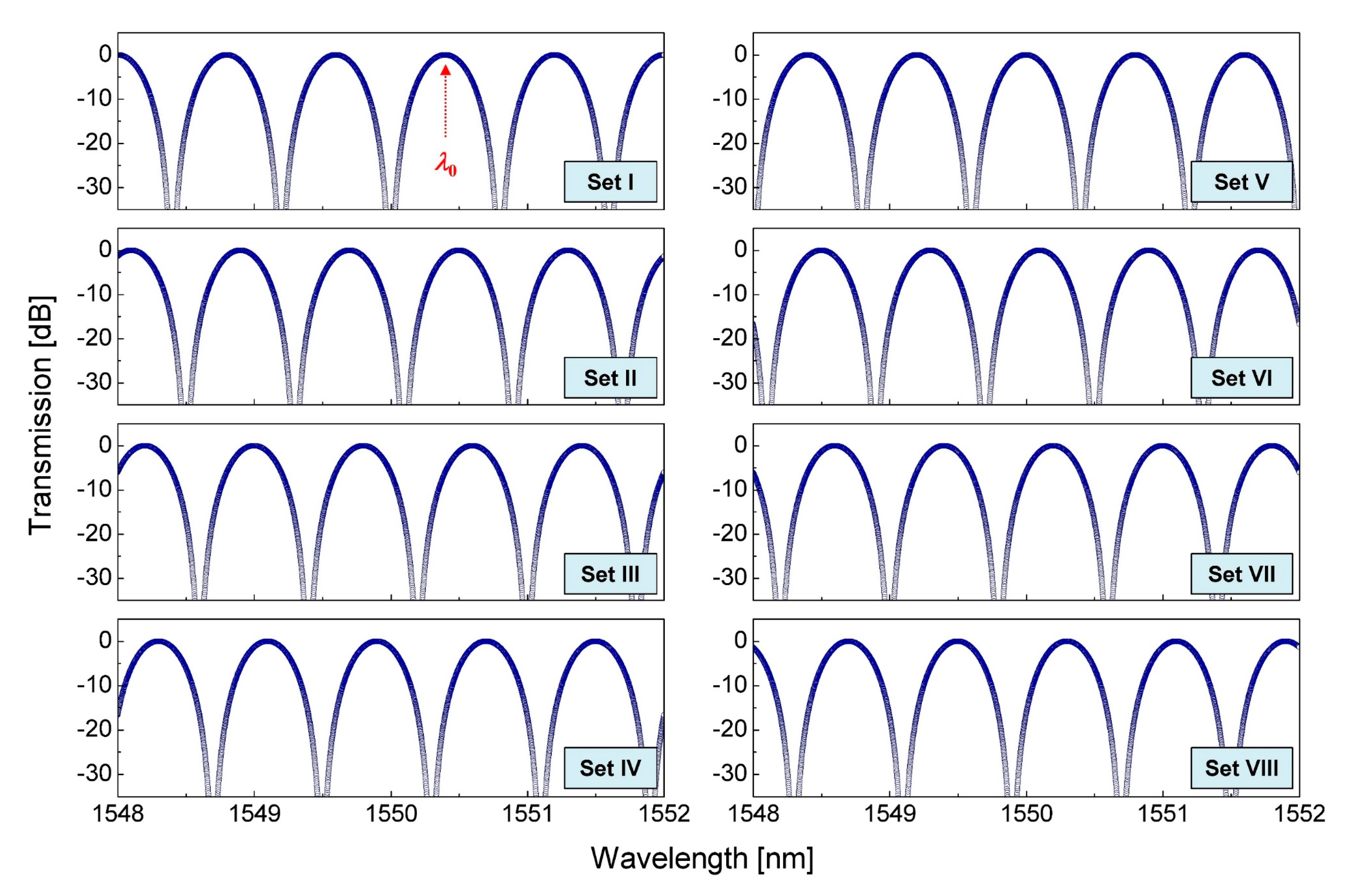
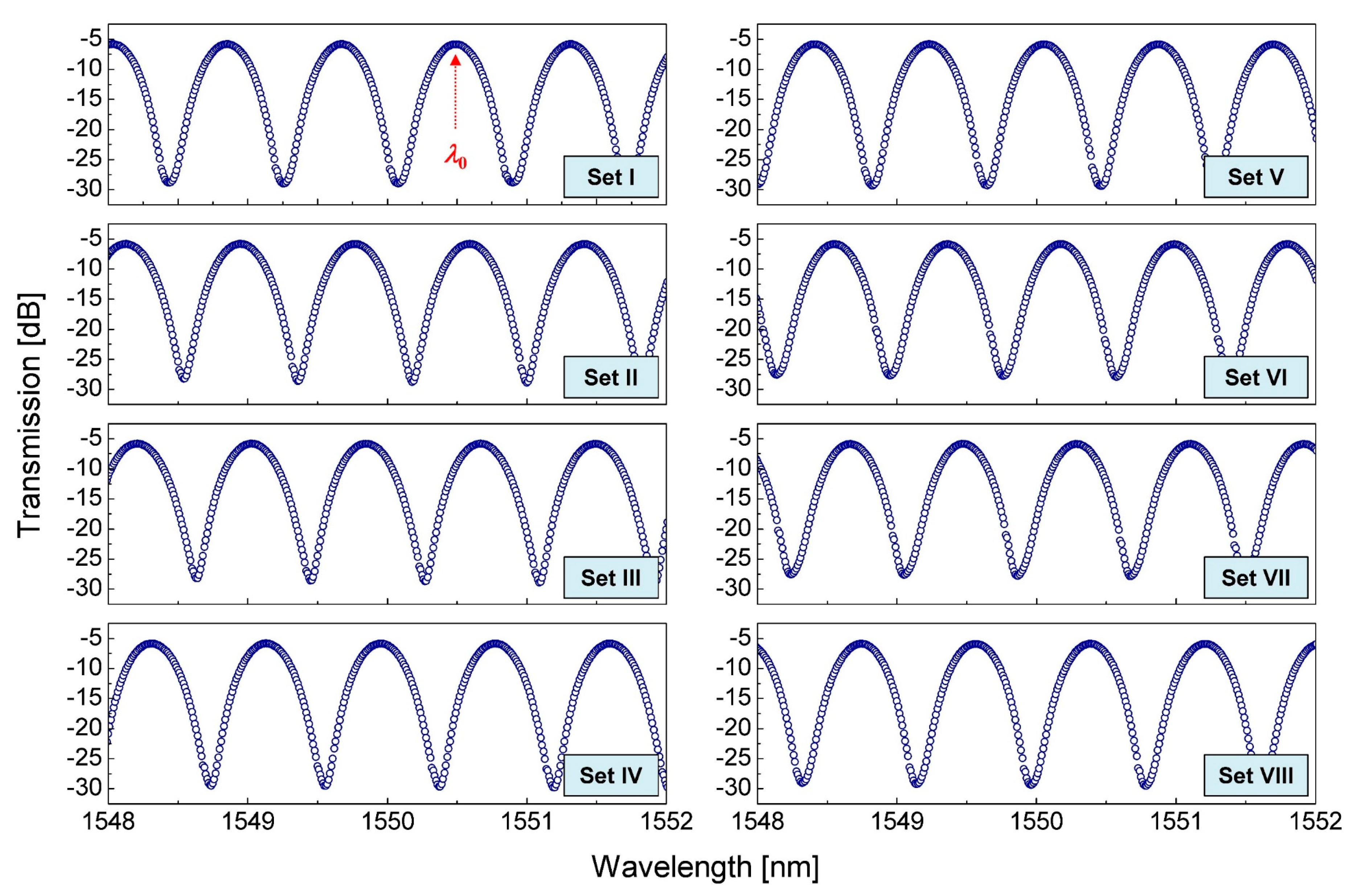
Figure 5 shows the narrowband transmission spectra, measured at the eight FAOA sets (sets I to VIII) in
Table 1. The resolution bandwidth of the optical spectrum analyzer was 0.05 nm during the measurement. For the eight comb spectra, the average insertion loss was measured to be ~5.88 dB and primarily attributed to the insertion losses of the PBS and wave retarders and the fiber splicing losses between different types of fibers (e.g., HBF and SMF). When we sequentially switched the FAOA set from set I to set VIII, the narrowband transmission spectrum moved towards a longer wavelength region by ~0.1 nm, leading to an entire wavelength shift of ~0.7 nm.
Figure 6a shows the variation of the peak wavelength denoted by
λ0 in
Figure 5, measured at the eight FAOA sets. A skyblue solid line indicates a linear fit of the measured data of
λ0. As can be figured out from the figure,
λ0 and
ψ have a highly linear relationship. From this linear fit, the adjusted
R2 value was evaluated as ~0.99723. It was also found that any desirable
ψ values between 0° and 360°, in addition to integer multiples of 45°, could be obtained by choosing appropriate FAOA’s. Thus, it is experimentally confirmed that the narrowband transmission spectrum can be continuously wavelength-tuned by elaborately adjusting FAOA sets of (
θQ1,
θH1,
θH2,
θQ2).
Figure 6b shows two superimposed plots of eight narrowband transmission spectra measured at the eight FAOA sets over a wavelength range from 1545 to 1555 nm; the upper plot displays four narrowband transmission spectra measured at the FAOA sets I, III, V, and VII, and the lower plot displays four narrowband transmission spectra measured at the FAOA sets II, IV, VI, and VIII. It is observed from the figure that the insertion losses are nearly even and the spectral flatness between transmission channels is less than 0.13 dB over the entire spectral range (10 nm). Moreover, the extinction ratio was measured to be more than 20 dB over the same wavelength range.


