Abstract
Previous studies on Connected and Automated Vehicles (CAVs) demonstrated the potential to coordinate the behaviors of multiple connected vehicles for traffic improvements. In this paper, we first propose a Conflict Duration Graph-based (CDG-based) coordination framework to resolve collisions and improve the traffic capacity of signal-free intersections. Secondly, a Speed Control-based Intersection Coordination Model (SICM) is developed to identify complex constraints in multi-vehicle collision scenarios. Thirdly, a geometric Translation-based Intersection Coordination Algorithm (TICA) is proposed to calculate the ideal location of time blocks in CDGs and then obtain the near-optimal design speed in the form of combinatorial optimization. Twelve groups of test scenarios with different traffic volumes were designed and tested on a MATLAB-based simulation platform. Simulation results showed that the proposed method can resolve all the collisions and instruct the vehicles to pass signal-free intersections collaboratively without stopping in low to medium level of congestion.
1. Introduction
With the rapid increase in population and transportation demand, intersections have become major bottlenecks in urban road networks as well as one of the most dangerous types of urban traffic infrastructures. According to an estimate from the Texas A&M Transportation Institute (TTI), due to traffic congestion, the population in the United States will consume 10 billion more hours commuting and purchase an extra 3.6 billion gallons of fuel at a total congestion cost of $237 billion by 2025 []. Besides, it has been reported that 21.5% of fatalities and 40% of accidents in the United States occur at intersections [].
In order to keep the balance between the growth in travel demand and the supply of transportation capacity, policy-makers and researchers have adopted various approaches to optimize road infrastructures and enhance road capacity in the past decades, including left-turn waiting areas [], variable approach lanes [], dynamic lane assignments [], and integrated waiting areas []. Nevertheless, congestion has gotten worse over the last several years. The reason why these approaches failed to significantly alleviate congestion is that they only optimized the structure of road macroscopically but ignored the impact of microscopic driving behaviors and traffic orders. Actually, drivers’ unnecessary acceleration and deceleration operations before reaching an intersection will cause speed fluctuations, which affect traffic efficiency, ride comfort, and energy consumption. Furthermore, the frequent start-stop cycle caused by traffic lights at signalized intersections will make drivers tired, agitated, or even angry and lead to a more aggressive and dangerous driving behavior called road rage, which may further aggravate congestion []. Recent technological advances in sensing, computing, and wireless communication have laid the foundation for the development of an approach based on Connected and Automated Vehicles (CAVs), which was named Cooperative, Connected, and Automated Mobility (CCAM) in Europe []. CAVs equipped with advanced onboard sensors, controllers, actuators, communicators, and other devices can perceive local and global environmental information and make intelligent decisions []. With the application of Vehicle-to-Everything (V2X) technologies, sensing and computing resources can be shared, and then vehicle information, including speed, acceleration, origin, and destination, can be obtained before the vehicle enters an intersection []. Furthermore, the behaviors and trajectories of vehicles can be optimized to coordinate with other vehicles for global traffic improvements []. It is expected that signal controllers will no longer be needed for the management and control at intersections in a future fully CAV-based environment [,,]. With the development of the Cooperative Vehicle Infrastructure System (CVIS), CAVs can realize autonomous traffic organization and management to ensure driving safety, improve traffic efficiency, save energy, and reduce emissions [,]. Therefore, a new traffic organization method called signal-free intersections comes into being.
Challenges in such a new organization method include three aspects:
- (1)
- First, traffic flows coming from all directions will enter the intersection at the same time, and their trajectories may form some conflict points in the central region. Therefore, the conflict resolution approach needs to guarantee that all vehicles can pass conflict points alternately rather than simultaneously. Furthermore, the number of vehicles entering the intersection at the same time will increase along with the traffic flow, which motivates us to consider resolution approaches suitable for different occasions, including two-vehicle collision and multi-vehicle collision.
- (2)
- Second, the spatio-temporal trajectory of CAVs needs to be optimized in the whole process, which starts at the approach road, goes through the intersection, and ends at the departure road. Therefore, each trajectory contains numerous decision variables, which makes the search space of trajectory optimization problems increase geometrically along with the traffic flow.
- (3)
- Third, the intersection manager needs to allocate the spatial and temporal resources of the intersection according to real-time traffic flow data, that is, to conduct online scheduling while keeping a balance between solving efficiency and quality. Therefore, the complexity of the optimization model and algorithm should not be too high so as to pursue higher computing efficiency and shorter computing time.
In this paper, we aim to address the challenges mentioned above and guide CAVs to cross signal-free intersection areas without stopping in medium to low traffic flows.
The remainder of this paper is organized as follows. Section 2 reviews related work. Section 3 introduces the autonomous traffic organization method of CAVs. In Section 4 we evaluate the performance of the proposed approach through simulation experiments. Section 5 provides the study’s conclusions and future research directions.
2. Related Work
As a new mode of traffic organization, signal-free intersections have attracted a lot of attention with various control approaches being proposed, which can be divided into two groups: distributed control and centralized control. The distributed control architecture regards vehicles as autonomous agents. Vehicles can pass the intersection through the strategic interaction via Vehicle-to-Vehicle (V2V) technology, which has the advantage of low infrastructure cost and low communication and computing requirements. Thus, an agent-based approach is commonly adopted to address the collaborative passing problem at a two-way two-lane intersection. Jin et al. [] proposed a multi-agent system and scheduled the departure times rather than just obeying the First-In-First-Out (FIFO) or the First-Arrive-First-Past (FAFP) rule. Bian et al. [] proposed a task-area partition framework to decompose the problem into three main tasks, including vehicle state observation, arriving time optimization, and trajectory tracking control problems, and then used a distributed algorithm to accomplish these tasks without global coordination. Wu et al. [] modeled the sequential movements of vehicles as Multi-Agent Markov Decision Processes (MAMDPs) and tried to alleviate the curse of dimensionality problem in multi-agent learning.
In the centralized control architecture, sensing and computing resources can be shared via the Vehicle-to-Infrastructure (V2I) technology, and global traffic improvement can be obtained. There is at least one task in the system conducted by the central controller, and V2I is used to capture the real-time information of traffic flow []. Some researchers [,] proposed reservation-based Autonomous Intersection Management (AIM) methods. In them, vehicles need to send messages to an intersection manager and reserve a sequence of spaces and time to cross the intersection. Then, the intersection manager will decide whether to approve or reject the requested reservation according to the intersection control policy. First-arrive-first-past is the most common policy; it takes the arrival time of each vehicle as a unique priority []. Therefore, the vehicle arriving earlier will have a higher priority to pass the intersection area. Lu et al. [] proposed a Discrete-time occupancies trajectory-based Intersection traffic Coordination Algorithm (DICA) and clarified the interaction between a CAV and an intersection control agent.
Some other studies in this field focused on the optimization of traffic sequences. Their objective function was usually related to safety performance [], traffic efficiency [], fuel consumption and pollutant emissions [,,], ride comfort [], fairness [], and other multiple performance measures []. A platoon mechanism has also been investigated to find the impact on integrated traffic performance [,]. Additionally, many researches tried to avoid conflicting vehicles entering the intersection at the same time to guarantee traffic safety, while some researches tried to allow vehicles with conflicting routes to enter intersections simultaneously so as to pursue higher traffic efficiency. To achieve this objective, Dresner et al. [] divided the intersection into grid cells or points, where only one vehicle is allowed to pass the cells or points at each time step to avoid collisions. Thus, other vehicles can exist within the same intersection cannot be within the same cell at the same time.
3. Methodology
3.1. Assumptions
As defined by relevant studies [,,], we also made several assumptions to quantify the potential benefits of the CAV environment.
- (1)
- All vehicles are fully automated and connected, and there are no human-driven vehicles, non-motor vehicles, or pedestrians on the road.
- (2)
- The influence of communication delay and packet loss can be ignored with the application of 5G networks.
- (3)
- There is a control center called the intersection manager that coordinates the sequence and motion of vehicles, and all the vehicles should follow the instructions of intersection manager.
- (4)
- The trajectory control error can be ignored; that is, the vehicle can move according to the spatio-temporal trajectory allocated by the intersection manager.
- (5)
- The intersection manager can obtain turning decisions of vehicles in advance through V2X technologies. Moreover, all the vehicles have completed lane changing before entering the entrance lane, while the left-turn lane is named lane no. 1, the straight lane is named lane no. 2, and the right-turn lane is named lane no. 3.
- (6)
- The length of vehicles is set to 3 or 5 m, representing compact vehicles and mid-sized vehicles, respectively, and the initial speed and arrival time are set as random values.
- (7)
- When the vehicle arrives at the entrance lane, the speed will be adjusted from the initial speed to a fixed speed specified by the intersection manager, and the maximum value of acceleration and deceleration are limited in order to ensure ride comfort, which still leaves room for energy-saving improvements.
Based on these assumptions, a typical two-way six-lane intersection sketch was designed (Figure 1). When the vehicle arrives in the communication area, it will send its passing request, origin and destination, location, and other motion information to the intersection manager. After that, the intersection manager will send back the passing guidance to instruct the vehicle to cross the approach road, intersection, and departure road with an ideal spatio-temporal trajectory, which can ensure both traffic safety and efficiency. The vehicle will follow the guidance to adjust its speed in the approach road, enter the intersection at the speed designated by the intersection manager, and then accelerate to the speed limit provided by law after entering the departure road.
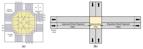
Figure 1.
Diagram of the two-way six-lane unsignalized intersection. (a) Intersection configuration; (b) road segment configuration.
We use direction and the turning information to number the 12 lanes. For example, E1 illustrates that the lane is coming from the east and can only turn left, and N2 illustrates that the lane is coming from the north and can only go straight. These 12 lanes will form 16 overlapping points (as shown in Figure 2 and Table 1) in the central region that pose a risk of collision accidents, which motivates us to design a conflict resolution mechanism.
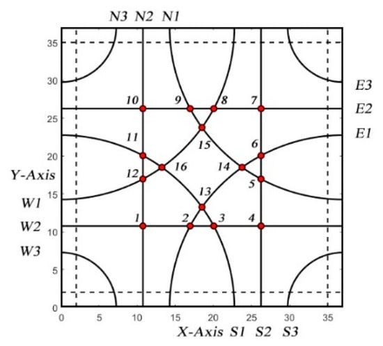
Figure 2.
All possible trajectories and overlapping points.

Table 1.
Conflict relationships among different lanes.
As shown in Figure 3, the potential trajectories of vehicles coming from one direction are assumed to be ideal geometrical lines. However, vehicles cannot be regarded as particles because the external sizes of vehicles have an impact on the occupation state of conflict points. As shown in Figure 4, the spatio-temporal trajectory of one vehicle is similar to a prism, and there will be a collision if the trajectories of two vehicles predicted by the intersection manager overlap, which indicates that the two vehicles have occupied the same conflict point at the same time.
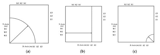
Figure 3.
Potential trajectories of vehicles. (a) Turn left from S1; (b) go straight from S2; (c) turn right from S3.
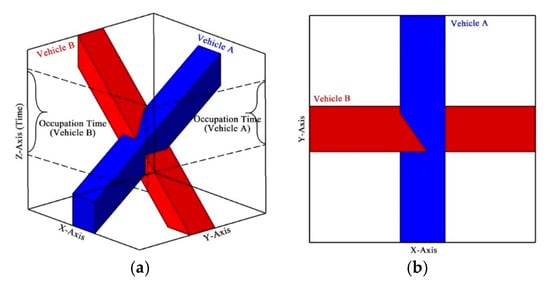
Figure 4.
Diagram of a collision from combined spatio-temporal domains. (a) 3D axonometric view; (b) 2D vertical view.
3.2. Procedure of Conflict Detection and Resolution
As we mentioned above, the intersection manager can obtain the motion information of CAVs, including arriving time, location, and speed by V2X technologies, and predict spatio-temporal trajectories of vehicles. Besides, the intersection manager will send warning messages to vehicles if conflicts are detected, and then adjust the speed to avoid collisions.
In this section, we use a two-vehicle collision scenario to introduce the proposed CDG-based conflict detection. As shown in Figure 5, vehicle A goes along lane W2 with an initial speed vA, vehicle B goes along lane S2 with an initial speed vB, and the two paths have an overlapping point called conflict point 4. If the two vehicles occupy the same conflict point at the same time, there will be a collision. On the contrary, it is feasible to drive at the initial speeds vA and vB, and that there will be no collision.
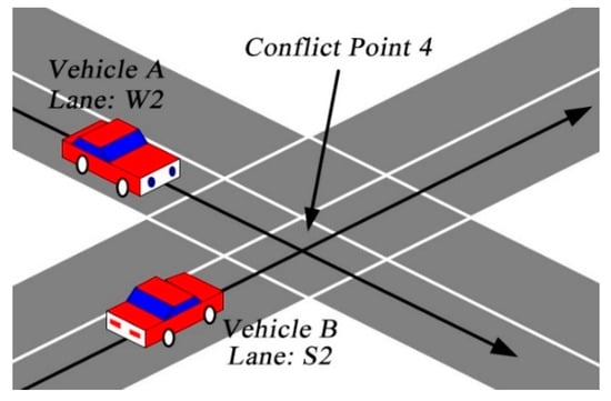
Figure 5.
Diagram of a potential collision accident.
Assuming that two vehicles keep their respective initial speeds after entering the approach road, we can predict the occupation time of the conflict point according to the following formula (taking vehicle A as an example):
where lA is the physical length of the vehicle, wA is its physical width and LA is its virtual length. The reason why we replace the original length with a larger artificial length (as shown in Figure 6) is to eliminate both communication and control errors caused by communication delay and packet loss, in order to prevent collisions accidents.
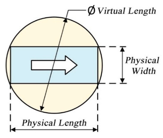
Figure 6.
Diagram of virtual length and physical width.
As shown in Figure 7a,b, the conflict point will be occupied when the head of vehicle A enters the overlapping region, and it will be released when the rear of the vehicle A entirely leaves the overlapping area. There will be no collision in Figure 7c if vehicle B does not contact the conflict point when vehicle A is occupying it. On the contrary, there will be a collision in Figure 7d.

Figure 7.
State of occupation. (a) Start of occupation; (b) end of occupation; (c) collision-free; (d) collision.
For the sake of visualization, we introduce the conflict-duration graph to express the crucial factors in spatio-temporal trajectories, for the reason that the trajectories will be too dense to detect conflicts as traffic flows rise. Hence, the conflict-duration graph, inspired by a Gantt chart, is used to represent the state of occupation of 16 conflict points inside the intersection. Among them, the horizontal axis of the CDG is used to represent the timestamp (the number of simulation steps experienced), and the vertical axis is used to represent the index of conflict points.
As shown in Figure 8, vehicle A goes along lane W2, which will occupy the first, second, third and fourth conflict points successively, and vehicle B goes along lane S2, which will correspondingly occupy the fourth, fifth, sixth and seventh conflict points. Each vehicle will occupy the conflict points on the path for a while and leave black time blocks on the graph. There will be no collision if they do not occupy the fourth conflict point at the same time. Otherwise, the overlapping areas will be marked red, representing a collision accident. The calculation method of the occupation time will be introduced later.

Figure 8.
Samples of conflict-duration graph. (a) Collision-free; (b) collision.
The procedures of conflict detection and resolution are introduced as follows (as shown in Figure 9):
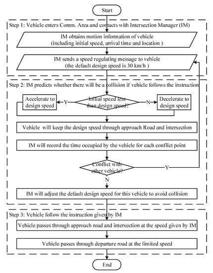
Figure 9.
Flowchart of conflict detection and resolution.
- Step 1: Assume that all the vehicles will communicate with the intersection manager in turn according to their arrival time after entering the communication area. Next, vehicles will report their motion information, including initial speed (in the range of 10 to 50 km/h), arrival time, and location via V2I technologies. At the same time, the intersection manager will send a speed regulation message to the vehicle, and the design speed is set to 30 km/h by default in order to keep a balance between efficiency and safety (speed limit is set to 50 km/h).
- Step 2: The intersection manager will predict the spatial-temporal trajectory of the vehicle and conduct a conflict detection procedure to check whether there will be a collision. (1) In the simulation, the vehicle will speed up or slow down to the speed designated by the intersection manager with a constant acceleration (1 m/s2) in the approach road. (2) It will keep the designated speed while going through the rest of the approach road and intersection. (3) The intersection manager will record the time occupied by the vehicle for each conflict and check whether it conflicts with other vehicles. If there will be a collision, the intersection manager will adjust the initial default design speed to ensure safety. The conflict resolution method that is the calculation method of the modified speed will be introduced later.
- Step 3: After a rigorous conflict detection performed by the intersection manager, the vehicle will follow the instructions that were proven safe to pass the intersection without collision. After that, it will speed up to the speed limit in the departure road to improve efficiency.
3.3. Speed Control-Based Intersection Coordination Model (SICM)
3.3.1. Calculation of Spatio-Temporal Trajectory
Before establishing the model, we need to study the computing method of the spatio-temporal trajectory. For the sake of clarity, some parameters and variables need to be classified (Table 2), which can be obtained via V2I techniques.

Table 2.
Notations and descriptions.
After that, the occupation time for the four conflict points of each vehicle can be calculated as follows (the procedures are shown in Figure 9).
- (1)
- The vehicle will accelerate uniformly from the initial speed to the design speed with acceleration in the approach lane, then we havewhere represents the time needed by the idth vehicle to accelerate uniformly and represents the distance traveled during acceleration.
- (2)
- The vehicle will move at a constant speed through the remaining part of the approach road and intersection until it enters the departure road, then we havewhere represents the time of constant motion, represents the index of four conflict points, represents the serial number of the ith conflict point through which the idth vehicle will pass, and represents the distance between the ith conflict point and the stop line at the intersection. Additionally, and represent the start and end time of occupation at the ith conflict point, respectively.
- (3)
- The vehicle will speed up to the speed limit in the departure road, and then we havewhere represents the time for the idth vehicle to accelerate uniformly and represents the distance traveled during acceleration.
- (4)
- The vehicle will move at the constant speed through the remaining part of the departure road, and then we havewhere represents the time of constant motion.
Aggregating all these formulas together, we can calculate the spatio-temporal trajectory of vehicles. Additionally, the time bocks in the conflict-duration graph can be calculated and located (as shown in Figure 10), while the and represent the start and end time of occupation at the ith conflict point.
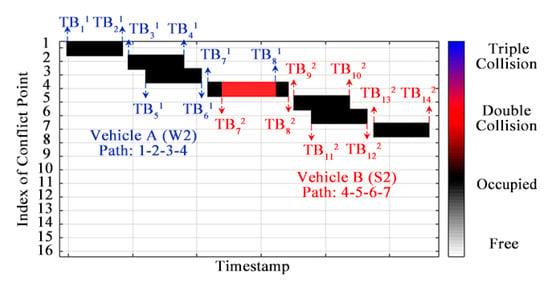
Figure 10.
The location of the time blocks of vehicle A and B.
3.3.2. Model Development
As mentioned above, we need to conduct the conflict resolution measure, which is used to adjust the speed of the vehicle in advance if there will be a collision (as shown in Figure 10). In this section, we will take vehicles A and B as an example to develop a conflict resolution model called the Speed Control-based Intersection Coordination Model (SICM).
- (1)
- Assume that the serial numbers of vehicles A and B are 1 and 2, respectively. If there will be a collision, the intersection manager will adjust the default design speed of the vehicles to avoid occupying the same conflict point at the same time. Therefore, we take the modified design speed as a decision variable as follows:
- (2)
- The decision variables should not exceed the speed limit, and the acceleration affected by the design speed should not exceed the mobility performance limit. Therefore,In addition, small errors in the model can lead to serious traffic accidents; thus, constraints on driving safety should also be set for the model, that is:where j is the serial number of conflict points and and represent the duration of occupation at the jth conflict point respectively.
- (3)
- We want to improve traffic efficiency; therefore, we set the optimize goal as:where represents the start time of occupation at the first conflict point, represents the end time of occupation at the fourth conflict point, and makespan represents the period of two vehicles occupying the intersection area.
- (4)
- The number of vehicles entering the intersection at the same time will increase along with the traffic flow, which may increase the risk of collision. Therefore, we need to modify the constraint conditions to address this multi-vehicle conflict resolution problem. We take a three-vehicle conflict as an example to illustrate the modification of constraints. Assuming that the serial numbers of the three vehicles are 1, 2, and 3, we have:where j is the serial number of conflict points, and , and represent the duration of occupation at the first, second and third conflict points, respectively.
3.4. Geometric-Translation Based Intersection Coordination Algorithm (TICA)
As we mentioned above, the intersection manager needs to allocate the spatial and temporal resources of the intersection according to real-time traffic flow data, that is, to conduct online scheduling while keeping a balance between solving efficiency and quality. Therefore, the complexity of the optimization algorithm should not be too high in order to pursue higher computing efficiency and shorter computing time. In this section, we will propose a Geometric Translation-based Intersection Coordination Algorithm (TICA) to address the problem.
In fact, the collision can be avoided if vehicle B can be delayed for a while to reach the fourth conflict point (as shown in Figure 11a). The expected time difference (as shown in Figure 11b) can be calculated as follows:
where and are known values, and represents the buffer time for ensuring safety. Furthermore, we can calculate the ideal time of vehicle B arriving at conflict point 4, that is
where represents the arriving time of vehicle B at the fourth conflict point after speed control.
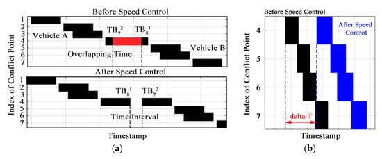
Figure 11.
Diagram of speed control. (a) Ideal conflict resolution results of vehicles A and B; (b) speed control of vehicle B.
After that, we can calculate the modified design speed for vehicle B based on the known ideal time difference. As shown in Figure 12, and represent the time needed to reach the fourth conflict point before and after speed control; and represent the time of acceleration before and after speed control. Therefore, we have:
where represents the expected time difference. Additionally, and represent the design speed given by the intersection manager before and after speed control, respectively. Among them, only and are unknown, and the relationship between the two variables is:
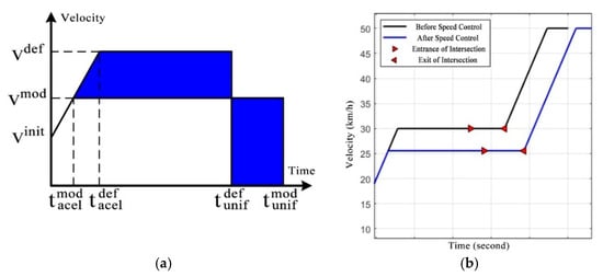
Figure 12.
Speed control solution for vehicle B. (a) Velocity difference before and after speed control; (b) speed control strategy.
Assume that the distance between the fourth conflict point and the stop line at the intersection are known, that is
where represents the distances of vehicle B between the fourth conflict point and the stop line. Besides, the movement distance of vehicle B before speed control and the distance after speed control can be calculated as follows:
It is obvious that s1 and are equal to ; therefore we have:
Aggregating all these formulas together, we can calculate and , which can guarantee the safety and efficiency of vehicles. The velocity difference of design speed before and after speed control can be calculated as:
The procedures of conflict detection and resolution strategy are concluded in Algorithm 1, and the details of TICA are shown in Algorithm 2. The algorithm framework, which has a computation complexity of , adopts an iterative method to generate optimal traffic solution for vehicles with no collisions, which can optimize vehicle sequences to reduce average delays and ensure safety with a linear computational complexity.
| Algorithm 1 Conflict detection and resolution strategy | |
| //id is the serial number of vehicles, num is the total number of vehicles. | |
| //index is the serial number of conflict points. | |
| //, , are arrival time, initial speed, and location of the idth vehicle. | |
| // is the default design speed, is the modified design speed. | |
| 1. | Begin |
| 2. | For id = 1 to num Do |
| 3. | flag = 1, = 30 km/h. |
| 4. | While flag == 1 Do |
| 5. | crashCount = 0; |
| 6. | Obtain motion information, including , , . |
| 7. | Calculate the location of the Time Blocks on Conflict-Duration-Graph. |
| 8. | For index = 1 to 16 Do |
| 9. | Record the time occupied by the idth vehicle for the indexth conflict point. |
| 10. | If the idth vehicle conflicts with other vehicles at the indexth conflict point |
| 11. | crashCount = crashCount+1. |
| 12. | End If |
| 13. | End for |
| 14. | If crashCount > 0//there are collisions existing on CDG |
| 15. | Calculate using TICA. |
| 16. | = . |
| 17. | Else |
| 18. | flag = 0. |
| 19. | Instruct the idth vehicle to pass the intersection area with . |
| 20. | End if |
| 21. | End While |
| 22. | End For |
| 23. | End |
| Algorithm 2 Geometric Translation-based Intersection Coordination Algorithm (TICA) | |
| // is the duration of occupation of the idth vehicle. | |
| //id1 is the serial number of the vehicle waiting for determining design speed. | |
| //id2 is the serial number of the vehicles of which design speed has determined. | |
| //Δt is the time difference before and after speed control. | |
| 1. | Begin |
| 2. | For index = 1 to 16 Do//index is the serial number of conflict point |
| 3. | For id2 = id1-1 to 1 Do |
| 4. | If |
| 5. | = length () |
| 6. | Calculate and using the formulas shown in Section 3.4. |
| 7. | End If |
| 8. | End For |
| 9. | End For |
| 10. | End |
4. Experimental Studies
4.1. Parameters and Simulation Setup
We operated the simulation experiments using MATLAB (R2018a, MathWorks, Natick, MA, USA), which provides a cost-effective, risk-free environment to explore the traffic management strategy and evaluate the proposed TICA algorithm. The specifications of the system used for the simulation are: Intel Core TM 2 processor, Quad CPUQ6700 @ 2.60 GHz, RAM-8 GB, and OS-Windows 10 Home 64-bit (Intel, Santa Clara, CA, USA). We selected a signal-free intersection of Tuanjie Avenue and Fenglin Road in Wuhan city, Hubei Province, China, as a test scenario, whose geometry is shown in Figure 13. For the sake of simplicity, the intersection has been simplified in the simulated road model, which contains three lanes at each entrance for “turn left”, “go straight”, and “turn right”, respectively.
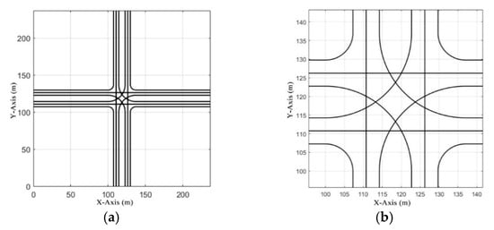
Figure 13.
The geometry of the unsignalized intersection. (a) Overview; (b) detailed drawing.
As shown in Table 3, the time step was set as 0.01 s, which provides a balance between motion control accuracy and computational time, and the width of the lane was set as 3.5 m, which affects the radius of the turning circle and the size of the intersection. The traffic flow was set from 1080 to 2160 vehicles per hour, and the initial speed of each vehicle was set from 10 to 50 km/h. Besides, the degree of traffic balance was set as [0.25 0.25 0.25 0.25], which represents that the amounts of vehicles coming from different directions are equal; the probability of turning was set as [0.3 0.5 0.2], which represents that 30% of vehicles will turn left, 50% will go straight and 20% will turn right. The length of vehicles was randomly set as 3 or 5 m, representing compact and middle-sized vehicles, respectively.

Table 3.
Simulation parameters setup.
Before the simulation experiments, we designed 12 groups of test scenarios with different volumes of traffic flows (1080 to 2160 vehicles per hour, veh/h) for evaluating the proposed conflict detection and resolution algorithm (as shown in Table 4). The number of vehicles passing through during a simulation was from 90 to 180 in proportion. Each traffic flow condition contained three randomly generated test scenarios, named A, B, and C. The details of each test scenario are contained in the sign-in sheet, which determines the initial state of vehicles (as shown in Table 5).

Table 4.
Code names for 12 test scenarios.

Table 5.
An example of a sign-in sheet of vehicles in the 90A test scenario.
4.2. Results and Discussions
In the simulation experiments, we applied the proposed TICA method to resolve conflicts in the intersection area. Examples of optimal spatio-temporal trajectories for vehicles generated by TICA are illustrated in Figure 14. As shown in Figure 14, the x-axis and y-axis represent the location of vehicles in the intersection area, and the z-axis represents the timeline of the simulation. The velocity sequence of each vehicle can be obtained from the spatio-temporal trajectories. The results of conflict detection and resolution for the 12 test scenarios are illustrated in Figure 15. As shown in Figure 15a, the number of potential collision accidents increased with the volume of traffic, which demonstrates the necessity for conflict resolution. As shown in Figure 15b, the number of vehicles that had to adjust their design speed also increased with the volume of traffic.
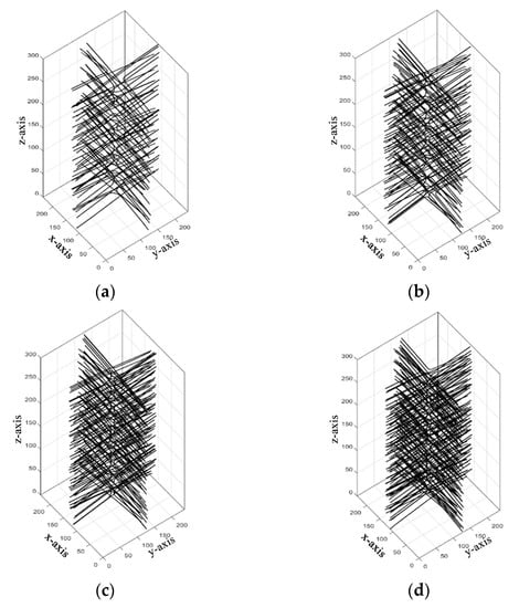
Figure 14.
Optimal spatio-temporal trajectories for vehicles in different test scenarios. (a) 90A; (b) 120A; (c) 150A; (d) 180A.
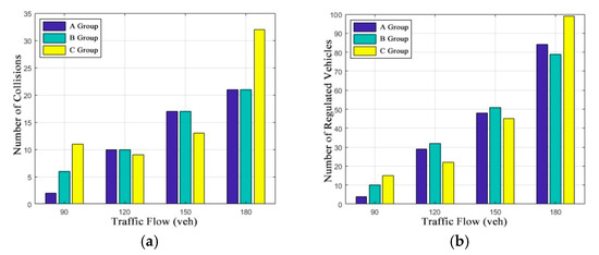
Figure 15.
Results of conflict detection and resolution for different test scenarios. (a) The number of potential collisions; (b) the number of regulated vehicles.
Next, we take a multi-vehicle collision accident in the 150A test scenario as an example to illustrate the detailed resolution process of the proposed method. As shown in Figure 16a, if all the vehicles follow a default design speed (30 km/h), there will be collision accidents occurring at the fourth, 10th, and 12th conflict points, of which motion information is shown in Table 6. As shown in Figure 16b, if vehicles follow the individual instructions given by the intersection manager, including a modified design speed and a driving strategy, all these collisions can be resolved. The 61th, 64th, 65th, and 66th vehicles are controlled by the intersection manager to slow the default speed down, making them arrive at conflict points later than before, which provides a buffer time for safe passage. The impacts of conflict resolution on regulated vehicles are shown in Figure 17 together with the modified design speed for each regulated vehicle in the 150A test scenario.
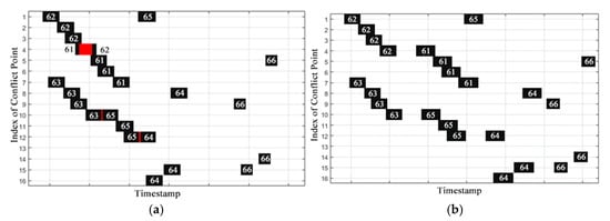
Figure 16.
A multi-vehicle collision in the 150A test scenario. (a) Before speed control; (b) after speed control.

Table 6.
Motion information in multi-vehicle collisions.
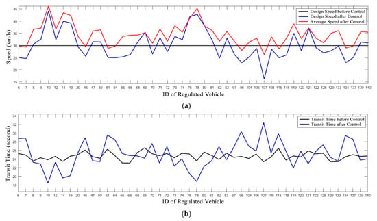
Figure 17.
Impacts of conflict resolution on regulated vehicles in the 150A test scenario. (a) Vehicle speed before and after speed control; (b) transit time before and after speed control.
Table 7 shows the evaluation indexes of the solutions for the 12 test scenarios. The average speed represents the average speed of vehicles in one test scenario; the transit time denotes the interval time between entering the entrance road and leaving the departure road; the delay time indicates the time difference before and after speed control. As shown in Table 7, all the collision accidents existing before could be resolved at the expense of traffic efficiency compared with the free flow situation, that is, a slight decline in average speeds as well as a slight growth in average transit time. The total delay showed an acceptable increase, which did not have much impact on efficiency.

Table 7.
Evaluation indexes of the solutions for the 12 test scenarios.
5. Conclusions and Future Work
In this study, a Conflict Duration Graph-based (CDG-based) coordination method for CAVs at signal-free intersections was proposed. The major contributions of this study can be summarized as follows:
- (1)
- We employed a CDG inspired by a Gantt chart to represent the crucial factors for scheduling in CAVs trajectories. After that, we established a CDG-based framework of conflict detection and resolution, which can show the occupation state of the conflict points and identify the existence of collision accidents in a visualization manner.
- (2)
- Considering that the number of vehicles entering the intersection at the same time will increase along with the traffic flow, we proposed a conflict resolution method for the multi-vehicle collision to ensure traffic safety and efficiency, which consists of a Speed Control-based Intersection Coordination Model (SICM) model and a Geometric Translation-based Intersection Coordination Algorithm (TICA). The SICM model takes the design speed as a decision variable to reduce the difficulty of controlling vehicle speed throughout and identifies constraints among multi-vehicle collision scenarios. The TICA algorithm allocates the spatial and temporal resources of intersections by translating time blocks into the form of combinatorial optimization in order to pursue higher computing efficiency and shorter computing time.
- (3)
- We developed a MATLAB-based simulation platform and designed 12 test scenarios to validate the proposed method. This platform provided a more flexible choice for integrated development than commercial traffic simulation software. The comparison results before and after speed control showed that the proposed algorithm can resolve all the collisions at some expense to traffic efficiency.
On the whole, the signal-free traffic mode is superior to the traditional signal-controlled mode with significant growth in the road capacity and a decline in transit delay per vehicle. Further, vehicles can cross signal-free intersection areas without stopping in low to medium traffic flows.
However, some limitations were observed in the present work:
- (1)
- The study could not address the coordination problem in mixed traffic flow and a partial CAV environment, which consists of CAVs, human-driven vehicles, pedestrians, etc. In more realistic situations, the other road users will also occupy the temporal-spatial resource and their trajectories will form some new overlapping points with the vehicle routes. Thus, we need to add some dynamic conflict points to the conflict-duration graph.
- (2)
- We assumed high-quality V2I/V2V communication with 5G networks, but the communication load, delay, and packet loss cannot be ignored under actual traffic conditions. Thus, we need to conduct a comprehensive simulation under the Veins framework, which combines the event-based network simulator OMNeT++ and the microscopic road traffic simulator SUMO (Simulation of Urban Mobility), to validate the proposed method in the future.
Author Contributions
Conceptualization, Z.D.; formal analysis, Q.H.; funding acquisition, Y.S.; investigation, L.L.; methodology, Z.D. and Y.S.; project administration, W.S.; resources, W.S.; software, Z.D.; supervision, W.S.; validation, Y.S.; visualization, Q.H.; writing—original draft, Z.D.; writing—review and editing, Y.S., Q.H., L.L. and W.S. All authors have read and agreed to the published version of the manuscript.
Funding
This research was funded by the National Key Research and Development Program of China (2018YFE0197700).
Conflicts of Interest
The funders had no role in the design of the study; in the collection, analyses, or interpretation of data; in the writing of the manuscript, or in the decision to publish the results. The authors declare no conflict of interest.
References
- Lasley, P. 2019 Urban Mobility Report. Available online: https://mobility.tamu.edu/umr/ (accessed on 20 July 2020).
- Choi, E.-H. Crash Factors in Intersection-Related Crashes: An On-Scene Perspective. Available online: https://trid.trb.org/view.aspx?id=1083638 (accessed on 20 July 2020).
- Ma, W.J.; Liu, Y.; Zhao, J.; Wu, N. Increasing the capacity of signalized intersections with left-turn waiting areas. Transp. Res. Part A Policy Pract. 2017, 105, 181–196. [Google Scholar] [CrossRef]
- Zhou, H.M.; Ding, J.; Qin, X. Optimization of Variable Approach Lane Use at Isolated Signalized Intersections. Transp. Res. Rec. 2016, 2556, 65–74. [Google Scholar] [CrossRef]
- Zhao, J.; Yao, J.; He, S.X.; Han, Y. Operational Efficiency Evaluation of Intersections with Dynamic Lane Assignment Using Field Data. J. Adv. Transp. 2017, 2017, 1–13. [Google Scholar] [CrossRef]
- Xia, X.M.; Ma, X.D.; Wang, J. Control Method for Signalized Intersection with Integrated Waiting Area. Appl. Sci. 2019, 9, 968. [Google Scholar] [CrossRef]
- Knoop, V.L.; Van Zuylen, H.J.; Hoogendoorn, S.P. Microscopic traffic behaviour near incidents. In Transportation and Traffic Theory 2009: Golden Jubilee; Springer: Berlin, Germany, 2009; pp. 75–97. [Google Scholar]
- Martinez, A.; Canibano, E.; Romo, J. Analysis of Low Cost Communication Technologies for V2I Applications. Appl. Sci. 2020, 10, 1249. [Google Scholar] [CrossRef]
- Wang, Y.P.; Cai, P.L.; Lu, G.Q. Cooperative autonomous traffic organization method for connected automated vehicles in multi-intersection road networks. Transp. Res. C-Emer 2020, 111, 458–476. [Google Scholar] [CrossRef]
- Li, Z.N.; Wu, Q.; Yu, H.; Chen, C.; Zhang, G.H.; Tian, Z.Z.; Prevedouros, P.D. Temporal-spatial dimension extension-based intersection control formulation for connected and autonomous vehicle systems. Transp. Res. C-Emerg. Technol. 2019, 104, 234–248. [Google Scholar] [CrossRef]
- Jin, Q.; Wu, G.; Boriboonsomsin, K.; Barth, M. Multi-Agent Intersection Management for Connected Vehicles using an Optimal Scheduling Approach. In Proceedings of the 2012 International Conference on Connected Vehicles and Expo, Beijing, China, 12–16 December 2012; IEEE: Piscataway, NJ, USA, 2012; pp. 185–190. [Google Scholar] [CrossRef]
- Meng, Y.; Li, L.; Wang, F.-Y.; Li, K.; Li, Z. Analysis of cooperative driving strategies for nonsignalized intersections. IEEE Trans. Veh. Technol. 2017, 67, 2900–2911. [Google Scholar] [CrossRef]
- Wu, Y.Y.; Chen, H.P.; Zhu, F. DCL-AIM: Decentralized coordination learning of autonomous intersection management for connected and automated vehicles. Transp. Res. C-Emer 2019, 103, 246–260. [Google Scholar] [CrossRef]
- Mirheli, A.; Hajibabai, L.; Hajbabaie, A. Development of a signal-head-free intersection control logic in a fully connected and autonomous vehicle environment. Transp. Res. Part C-Emerg. Technol. 2018, 92, 412–425. [Google Scholar] [CrossRef]
- Zhang, K.; Xie, C.; Wang, Y.; Wang, M.; de La Fortelle, A.; Zhang, W.; Duan, Z.J.A.S. Service-Oriented Cooperation Policies for Intelligent Ground Vehicles Approaching Intersections. Appl. Sci. 2018, 8, 1647. [Google Scholar] [CrossRef]
- Shin, D.; Yi, S.; Park, K.-M.; Park, M.J.A.S. An Interacting Multiple Model Approach for Target Intent Estimation at Urban Intersection for Application to Automated Driving Vehicle. Appl. Sci. 2020, 10, 2138. [Google Scholar] [CrossRef]
- Bian, Y.; Li, S.E.; Ren, W.; Wang, J.; Li, K.; Liu, H. Cooperation of Multiple Connected Vehicles at Unsignalized Intersections: Distributed Observation, Optimization, and Control. IEEE Trans. Ind. Electron. 2019, 67, 10744–10754. [Google Scholar] [CrossRef]
- Rios-Torres, J.; Malikopoulos, A.A. A Survey on the Coordination of Connected and Automated Vehicles at Intersections and Merging at Highway On-Ramps. IEEE Trans. Intell. Transp. Syst. 2017, 18, 1066–1077. [Google Scholar] [CrossRef]
- Carlin, D.; Boyles, S.D.; Stone, P. Auction-based autonomous intersection management. In Proceedings of the 16th International IEEE Conference on Intelligent Transportation Systems (ITSC), Hague, The Netherlands, 6–9 October 2013; IEEE: Piscataway, NJ, USA, 2013; pp. 529–534. [Google Scholar]
- Vasirani, M.; Ossowski, S. A Market-Inspired Approach for Intersection Management in Urban Road Traffic Networks. J. Artif. Intell. Res. 2012, 43, 621–659. [Google Scholar] [CrossRef]
- Lu, Q.; Kim, K.-D. Autonomous and connected intersection crossing traffic management using discrete-time occupancies trajectory. Appl. Intell. 2019, 49, 1621–1635. [Google Scholar] [CrossRef]
- Levin, M.W.; Fritz, H.; Boyles, S.D. On Optimizing Reservation-Based Intersection Controls. IEEE Trans. Intell. Transp. Syst. 2017, 18, 505–515. [Google Scholar] [CrossRef]
- Mahbub, A.M.I.; Malikopoulos, A.A.; Zhao, L.H. Decentralized optimal coordination of connected and automated vehicles for multiple traffic scenarios. Automatica 2020, 117, 7. [Google Scholar] [CrossRef]
- Jin, Q.; Wu, G.; Boriboonsomsin, K.; Barth, M.J. Power-Based Optimal Longitudinal Control for a Connected Eco-Driving System. IEEE Trans. Intell. Transp. Syst. 2016, 17, 2900–2910. [Google Scholar] [CrossRef]
- Wang, Z.; Wu, G.; Barth, M.J. Cooperative Eco-Driving at Signalized Intersections in a Partially Connected and Automated Vehicle Environment. IEEE Trans. Intell. Transp. Syst. 2020, 21, 2029–2038. [Google Scholar] [CrossRef]
- Mirheli, A.; Tajalli, M.; Hajibabai, L.; Hajbabaie, A. A consensus-based distributed trajectory control in a signal-free intersection. Transp. Res. Part C-Emerg. Technol. 2019, 100, 161–176. [Google Scholar] [CrossRef]
- Wu, J.; Ghosal, D.; Zhang, M.; Chuah, C.-N. Delay-Based Traffic Signal Control for Throughput Optimality and Fairness at an Isolated Intersection. IEEE Trans. Veh. Technol. 2018, 67, 896–909. [Google Scholar] [CrossRef]
- Guo, Y.; Ma, J.Q.; Xiong, C.F.; Li, X.P.; Zhou, F.; Hao, W. Joint optimization of vehicle trajectories and intersection controllers with connected automated vehicles: Combined dynamic programming and shooting heuristic approach. Transp. Res. C-Emerg. 2019, 98, 54–72. [Google Scholar] [CrossRef]
- Jin, Q.; Wu, G.; Boriboonsomsin, K.; Barth, M. Platoon-Based Multi-Agent Intersection Management for Connected Vehicle. In Proceedings of the 16th International IEEE Conference on Intelligent Transportation Systems, Hague, The Netherlands, 6–9 October 2013; IEEE: Piscataway, NJ, USA, 2013; pp. 1462–1467. [Google Scholar]
- Lioris, J.; Pedarsani, R.; Tascikaraoglu, F.Y.; Varaiya, P. Platoons of connected vehicles can double throughput in urban roads. Transp. Res. C-Emerg. 2017, 77, 292–305. [Google Scholar] [CrossRef]
- Dresner, K.; Stone, P. A multiagent approach to autonomous intersection management. J. Artif. Intell. Res. 2008, 31, 591–656. [Google Scholar] [CrossRef]
© 2020 by the authors. Licensee MDPI, Basel, Switzerland. This article is an open access article distributed under the terms and conditions of the Creative Commons Attribution (CC BY) license (http://creativecommons.org/licenses/by/4.0/).