Analysis of the Thermomechanical Fatigue Behavior of Fully Ferritic High Chromium Steel Crofer®22 H with Cyclic Indentation Testing


Abstract
:1. Introduction
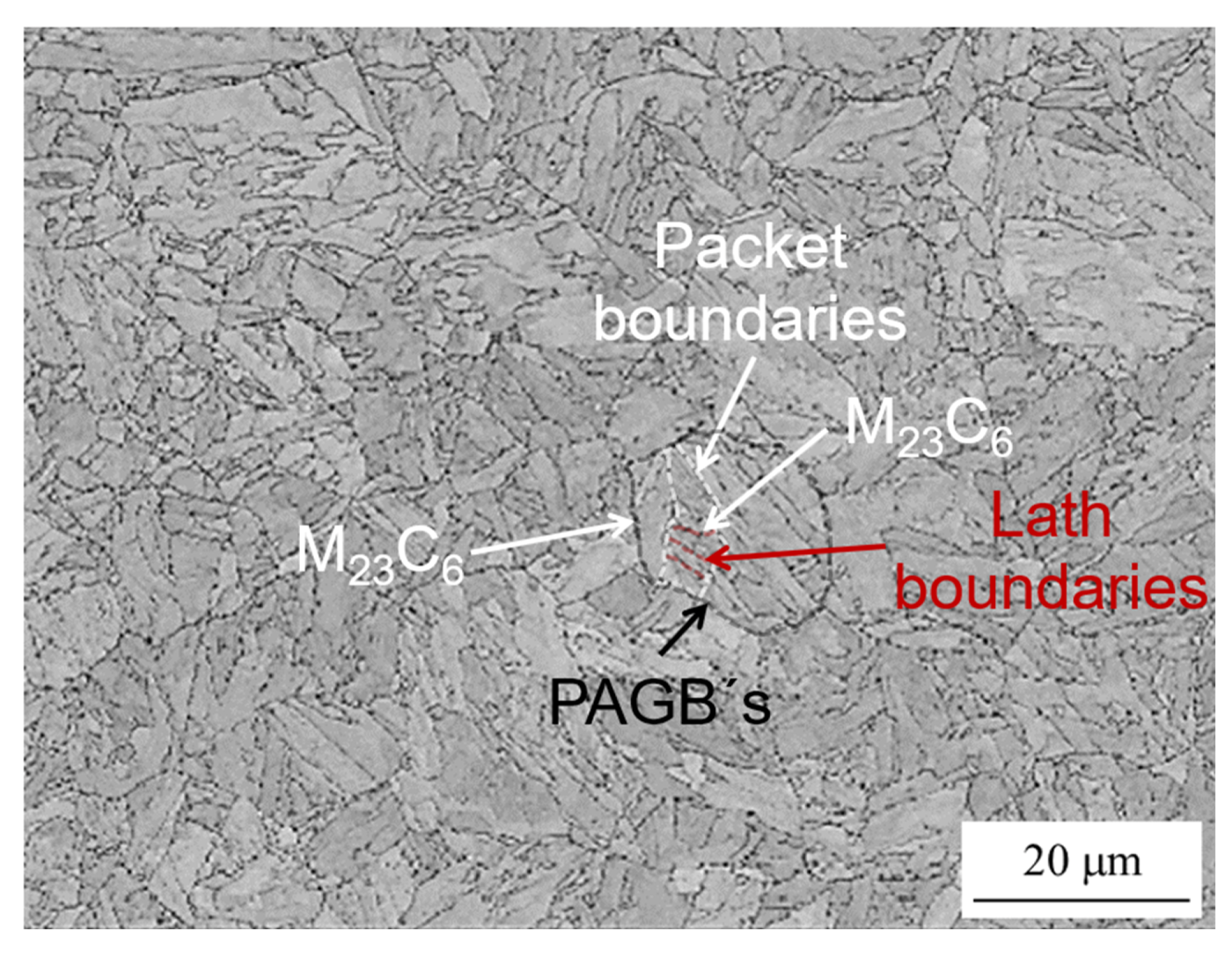
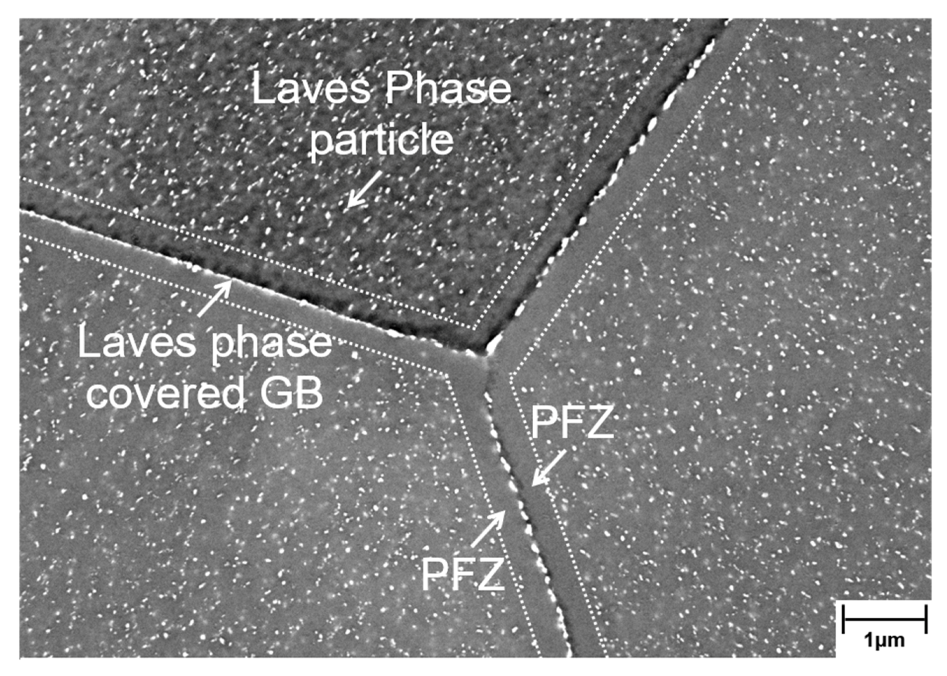
2. Materials
3. Methods
4. Results and Discussion
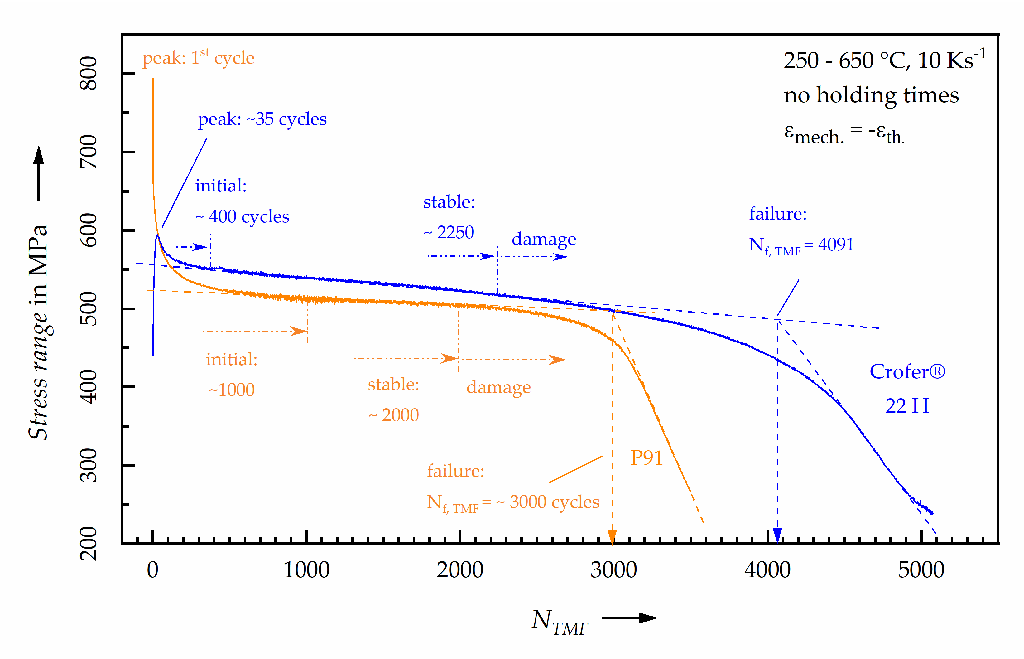
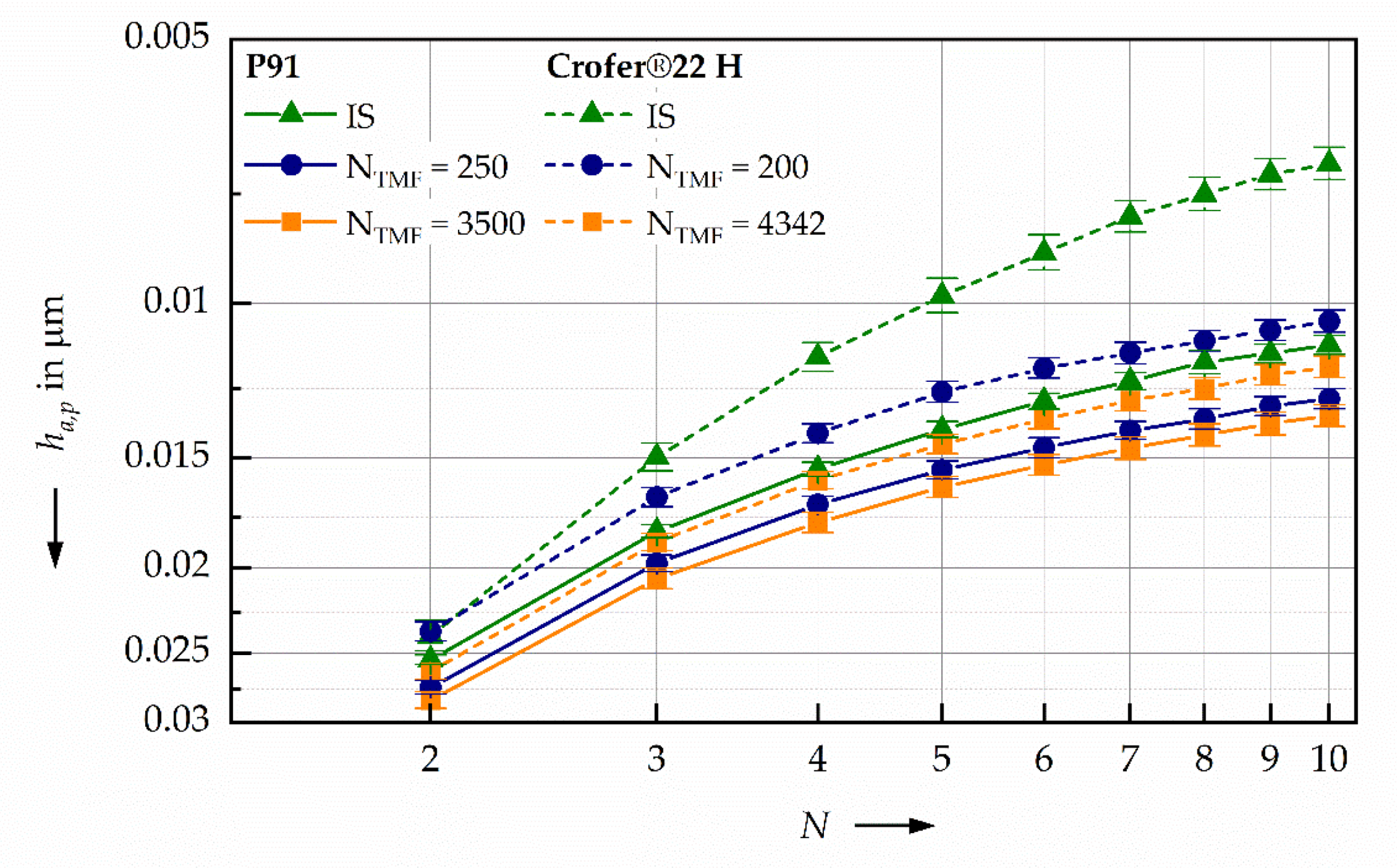
4.1. Evolution of Cyclic Hardening Potential and Hardness During TMF Loading
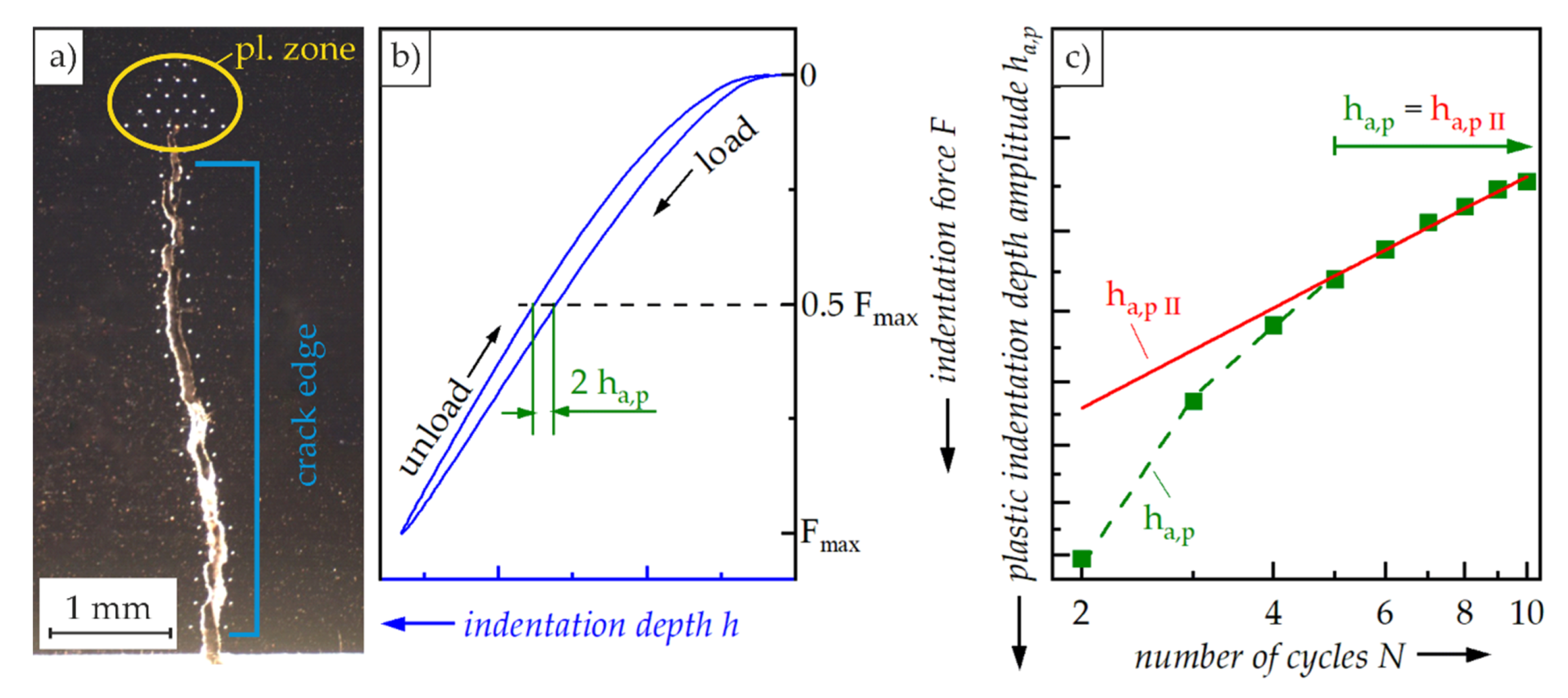
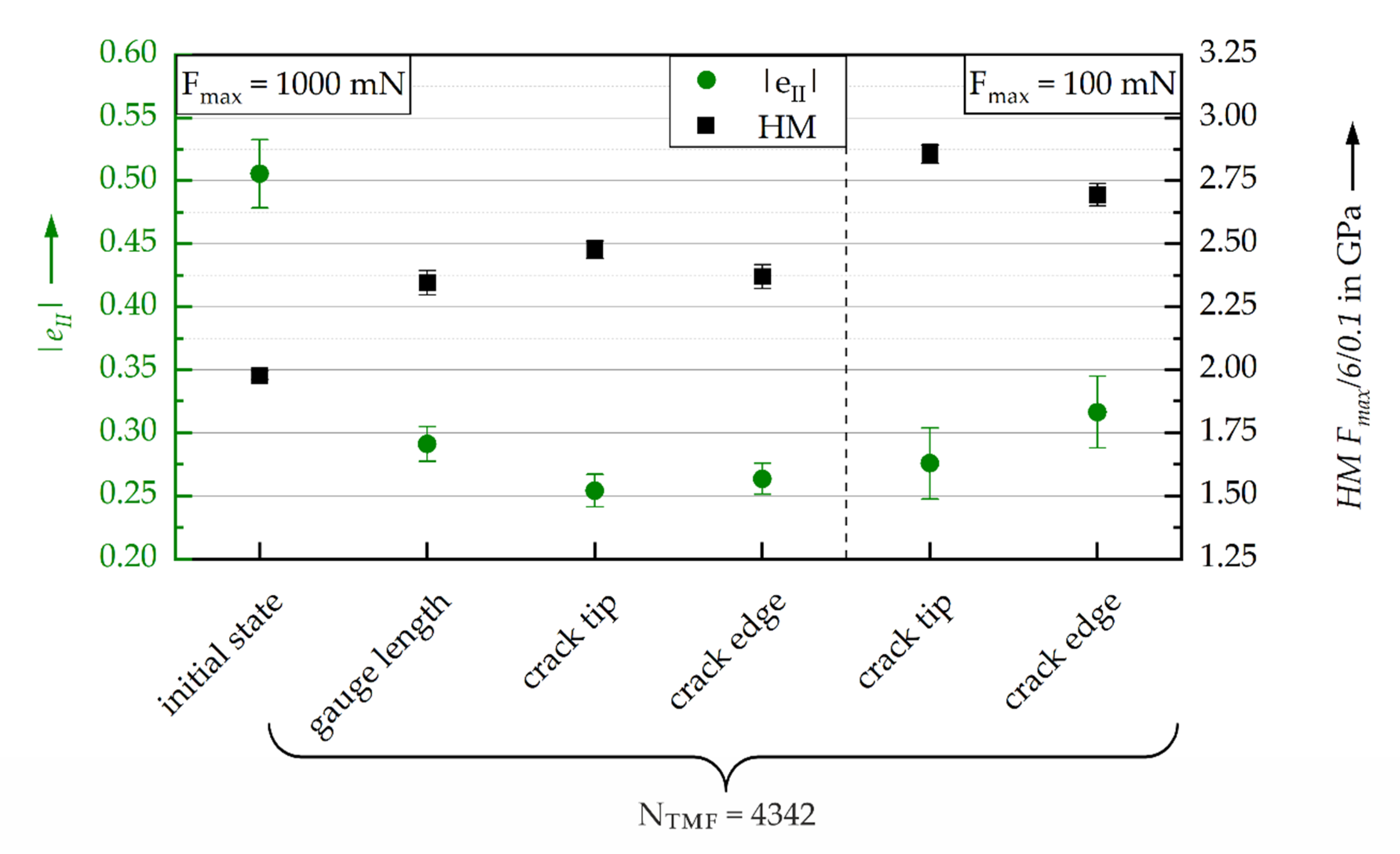
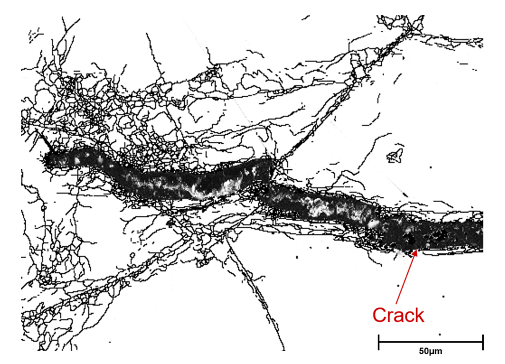
4.2. Investigation of the Local Cyclic Hardening Potential and Hardness in the Vicinity of a Fatigue Crack
5. Conclusions
- In the initial state, Crofer®22 H has a higher damage tolerance compared to P91, which correlates to higher TMF-lifetime;
- After approximately half of TMF-lifetime, an increase of damage tolerance can be observed for Crofer®22 H, which is not seen for P91 and correlates with changes of the Laves phase particle size and distribution;
- Polygonization, resulting from degradation of martensite lath structure in P91, does not influence the microhardness, as well as cyclic hardening potential obtained in CITs;
- For Crofer®22 H, the changes in damage tolerance correlate well with the cyclic deformation behavior observed in TMF-experiment and the accompanied microstructural changes;
- The cyclic hardening potential, and hence, damage tolerance, as well as hardness, is different between the crack tip and crack edges in Crofer®22 H;
- CITs are a powerful means to analyze the TMF-induced changes in mechanical properties, i.e., cyclic hardening potential, as well as for the investigation of locally restricted changes in the material’s cyclic deformation behavior.
Author Contributions
Funding
Acknowledgments
Conflicts of Interest
References
- Holdsworth, S. Creep-Fatigue Crack Growth in Power Plant Steels. Trans. Indian Inst. Met. 2015, 69, 353–358. [Google Scholar] [CrossRef]
- Kuhn, B.; Talik, M.; Zurek, J.; Beck, T.; Quadakkers, W.J.; Singheiser, L.S. Development of High Chromium Ferritic Steels Strengthened by Intermetallic Phases. In Proceedings of the Seventh International Conference of Advances in Materials Technology for Fossil Power Plants, Waikoloa, HI, USA, 22–25 October 2013. [Google Scholar]
- Pandey, C.; Mahapatra, M.M.; Kumar, P.; Saini, N. Some studies on P91 steel and their weldments. J. Alloys Compd. 2018, 743, 332–364. [Google Scholar] [CrossRef]
- Kuhn, B.; Talik, M.; Niewolak, L.; Zurek, J.; Hattendorf, H.; Ennis, P.; Quadakkers, W.J.; Beck, T.; Singheiser, L. Development of high chromium ferritic steels strengthened by intermetallic phases. Mater. Sci. Eng. A 2014, 594, 372–380. [Google Scholar] [CrossRef]
- Kuhn, B.; Barrilao, J.L.; Fischer, T. Impact of Thermomechanical Fatigue on Microstructure Evolution of a Ferritic-Martensitic 9 Cr and a Ferritic, Stainless 22 Cr Steel. Appl. Sci. 2020, 10, 6338. [Google Scholar] [CrossRef]
- Kuhn, B.; Talik, M.; Fischer, T.; Fan, X.; Yamamoto, Y.; Barrilao, J.L. Science and Technology of High Performance Ferritic (HiperFer) Stainless Steels. Metals 2020, 10, 463. [Google Scholar] [CrossRef] [Green Version]
- Mughrabi, H. Cyclic Slip Irreversibilities and the Evolution of Fatigue Damage. Met. Mater. Trans. A 2009, 40, 431–453. [Google Scholar] [CrossRef]
- Link, R.; Yang, L.; Fatemi, A. Cumulative Fatigue Damage Mechanisms and Quantifying Parameters: A Literature Review. J. Test. Eval. 1998, 26, 89–100. [Google Scholar] [CrossRef]
- Lemaitre, J.; Dufailly, J. Damage measurements. Eng. Fract. Mech. 1987, 28, 643–661. [Google Scholar] [CrossRef]
- Šulko, M.; Vladimír, C.; Kepka, M. Possibility of fatigue damage detection by non-destructive measurement of the surface hardness. Procedia Struct. Integr. 2017, 7, 262–267. [Google Scholar] [CrossRef]
- Liu, M.; Lin, J.-Y.; Lu, C.; Tieu, K.; Zhou, K.; Koseki, T. Progress in Indentation Study of Materials via Both Experimental and Numerical Methods. Crystals 2017, 7, 258. [Google Scholar] [CrossRef]
- Hay, J.L.; Pharr, G.M. Instrumented Indentation Testing. In Mechanical Testing and Evaluation, 11th ed.; Kuhn, H., Ed.; ASM International: Geauga County, OH, USA, 2000; pp. 231–242. ISBN 0871703890. [Google Scholar]
- Görzen, D.; Schwich, H.; Blinn, B.; Bleck, W.; Beck, T. Influence of different precipitation states of Cu on the quasi-static and cyclic deformation behavior of Cu alloyed steels with different carbon contents. Int. J. Fatigue 2020, 136, 105587. [Google Scholar] [CrossRef]
- Saraswati, T.; Sritharan, T.; Mhaisalkar, S.G.; Breach, C.; Wulff, F. Cyclic loading as an extended nanoindentation technique. Mater. Sci. Eng. A 2006, 423, 14–18. [Google Scholar] [CrossRef]
- Kramer, H.S.; Starke, P.; Klein, M.; Eifler, D. Cyclic hardness test PHYBALCHT – Short-time procedure to evaluate fatigue properties of metallic materials. Int. J. Fatigue 2014, 63, 78–84. [Google Scholar] [CrossRef]
- Blinn, B.; Görzen, D.; Klein, M.; Eifler, D.; Beck, T. PhyBaLCHT—Influence of indentation force on the results of cyclic hardness tests and investigations of comparability to uniaxial fatigue loading. Int. J. Fatigue 2019, 119, 78–88. [Google Scholar] [CrossRef]
- Blinn, B.; Ley, M.; Buschhorn, N.; Teutsch, R.; Beck, T.; Blinn, B. Investigation of the anisotropic fatigue behavior of additively manufactured structures made of AISI 316L with short-time procedures PhyBaLLIT and PhyBaLCHT. Int. J. Fatigue 2019, 124, 389–399. [Google Scholar] [CrossRef]
- Blinn, B.; Krebs, F.; Ley, M.; Teutsch, R.; Beck, T. Determination of the influence of a stress-relief heat treatment and additively manufactured surface on the fatigue behavior of selectively laser melted AISI 316L by using efficient short-time procedures. Int. J. Fatigue 2020, 131, 105301. [Google Scholar] [CrossRef]
- Durst, K.; Backes, B.; Göken, M. Indentation size effect in metallic materials: Correcting for the size of the plastic zone. Scr. Mater. 2005, 52, 1093–1097. [Google Scholar] [CrossRef]
- Sadrabadi, P.; Durst, K.; Göken, M. Study on the indentation size effect in CaF2: Dislocation structure and hardness. Acta Mater. 2009, 57, 1281–1289. [Google Scholar] [CrossRef]
- Klein, M.W.; Blinn, B.; Smaga, M.; Beck, T. High cycle fatigue behavior of high-Mn TWIP steel with different surface morphologies. Int. J. Fatigue 2020, 134, 105499. [Google Scholar] [CrossRef]
- Nix, W.D.; Gao, H. Indentation size effects in crystalline materials: A law for strain gradient plasticity. J. Mech. Phys. Solids 1998, 46, 411–425. [Google Scholar] [CrossRef]
- Masuyama, F. Advances in Physical Metallurgy and Processing of Steels. History of Power Plants and Progress in Heat Resistant Steels. ISIJ Int. 2001, 41, 612–625. [Google Scholar] [CrossRef]
- Pandey, C.; Giri, A.; Mahapatra, M. Evolution of phases in P91 steel in various heat treatment conditions and their effect on microstructure stability and mechanical properties. Mater. Sci. Eng. A 2016, 664, 58–74. [Google Scholar] [CrossRef]
- Quadakkers, W.J.; Wijnandsrade, N.L.; Niewolak, L.; Ennis, P.J. Kriechfester Ferritischer Stahl (Creep-Resistant Ferritic Steel). Patent DE102006007598A1, 30 August 2007. [Google Scholar]
- Schiller, G.; Franco, T.; Henne, R.; Lang, M.; Szabo, P.; Finkenwirth, O.; Kuhn, B.; Wetzel, F.-J. Development of Thin-Film SOFC for Stationary and Mobile Application by Using Plasma Deposition Technology. ECS Proc. Vol. 2003, 1051–1058. [Google Scholar] [CrossRef]
- Froitzheim, J.; Meier, G.; Niewolak, L.; Ennis, P.; Hattendorf, H.; Singheiser, L.; Quadakkers, W.J. Development of high strength ferritic steel for interconnect application in SOFCs. J. Power Sources 2008, 178, 163–173. [Google Scholar] [CrossRef]
- Hsiao, Z.-W.; Kuhn, B.; Chen, D.; Singheiser, L.; Kuo, J.-C.; Lin, D.-Y. Characterization of Laves phase in Crofer 22 H stainless steel. Micron 2015, 74, 59–64. [Google Scholar] [CrossRef]
- Hsiao, Z.W.; Kuhn, B.; Yang, S.M.; Yang, L.C.; Huang, S.Y.; Singheiser, L.; Kuo, J.C.; Lin, D.Y. The Influence of Deformation on the Precipitation Behavior of a Ferritic Stainless Steel. In Proceedings of the 10th Liége Conference on Materials for Advanced Power Engineering, Liége, Belgium, 14–17 September 2014; Lecomte-Beckers, J., Dedry, O., Oakey, J., Kuhn, B., Eds.; pp. 349–358. [Google Scholar]
- Pöpperlová, J.; Fan, X.; Kuhn, B.; Bleck, W.; Krupp, U. Impact of Tungsten on Thermomechanically Induced Precipitation of Laves Phase in High Performance Ferritic (HiperFer) Stainless Steels. Appl. Sci. 2020, 10, 4472. [Google Scholar] [CrossRef]
- Madyira, D.M.; Liebenberg, J.; Kaymacki, A. Comparative Characterization of P91 and 10CrMo9-10 Creep Resistant Steel Welds. Procedia Manuf. 2017, 8, 345–352. [Google Scholar] [CrossRef]
- Crofer® 22 H. Material Data Sheet No. 4050; ThyssenKrupp VDM GmbH: Werdohl, Germany, June 2010. [Google Scholar]
- Hähner, P.; Affeldt, E.; Beck, T.; Klingelhöffer, H.; Loveday, M.; Rinaldi, C. Validated Code-of-Practice for Thermo-Mechanical Fatigue Testing; Joint Research Centre: Luxembourg, 2006. [Google Scholar]
- Besel, M.; Breitbarth, E. Advanced analysis of crack tip plastic zone under cyclic loading. Int. J. Fatigue 2016, 93, 92–108. [Google Scholar] [CrossRef]


| Material | C | N | Cr | Mn | Si | Nb | W | V | Al | Ni | Mo | La | Ti |
| P91 | 0.1 | 0.051 | 8.1 | 0.46 | – | 0.07 | – | 0.18 | 0.34 | 0.33 | 0.92 | – | – |
| Crofer®22 H | <0.01 | <0.01 | 22.93 | 0.43 | 0.21 | 0.51 | 1.94 | – | – | – | – | 0.08 | 0.07 |
© 2020 by the authors. Licensee MDPI, Basel, Switzerland. This article is an open access article distributed under the terms and conditions of the Creative Commons Attribution (CC BY) license (http://creativecommons.org/licenses/by/4.0/).
Share and Cite
Blinn, B.; Görzen, D.; Fischer, T.; Kuhn, B.; Beck, T. Analysis of the Thermomechanical Fatigue Behavior of Fully Ferritic High Chromium Steel Crofer®22 H with Cyclic Indentation Testing. Appl. Sci. 2020, 10, 6461. https://doi.org/10.3390/app10186461
Blinn B, Görzen D, Fischer T, Kuhn B, Beck T. Analysis of the Thermomechanical Fatigue Behavior of Fully Ferritic High Chromium Steel Crofer®22 H with Cyclic Indentation Testing. Applied Sciences. 2020; 10(18):6461. https://doi.org/10.3390/app10186461
Chicago/Turabian StyleBlinn, Bastian, David Görzen, Torsten Fischer, Bernd Kuhn, and Tilmann Beck. 2020. "Analysis of the Thermomechanical Fatigue Behavior of Fully Ferritic High Chromium Steel Crofer®22 H with Cyclic Indentation Testing" Applied Sciences 10, no. 18: 6461. https://doi.org/10.3390/app10186461
APA StyleBlinn, B., Görzen, D., Fischer, T., Kuhn, B., & Beck, T. (2020). Analysis of the Thermomechanical Fatigue Behavior of Fully Ferritic High Chromium Steel Crofer®22 H with Cyclic Indentation Testing. Applied Sciences, 10(18), 6461. https://doi.org/10.3390/app10186461