Article

Energy Management of a Multi-Source Vehicle by λ-Control

1
Department of Electronics, Electrical Engineering and Automation, Faculty of Sciences and Technology, Univ. Lille, Arts et Metiers Institute of Technology, Centrale Lille, Yncrea Hauts-de-France, ULR 2697-L2EP, F-59000 Lille, France
2
AME-Eco7, Univ Gustave Eiffel, IFSTTAR, Univ Lyon, F-69675 Lyon, France
3
MEGEVH, French Research Network on Electrified Vehicles, 59650 Villeneuve D’Ascq, France
*
Author to whom correspondence should be addressed.
Appl. Sci. 2020, 10(18), 6541; https://doi.org/10.3390/app10186541
Submission received: 24 July 2020 / Revised: 8 September 2020 / Accepted: 16 September 2020 / Published: 18 September 2020
(This article belongs to the Section Energy Science and Technology)

Abstract

:
This paper deals with the real-time energy management of a fuel cell/battery/supercapacitors energy storage system for electric vehicles. The association of the battery and the supercapacitors with the fuel cell aims to reduce the hydrogen consumption while limiting the constraints on the fuel cell and the battery. In this paper, a real-time optimization-based energy management strategy by λ-control is proposed. Simulation results on a standard driving cycle show that the hydrogen consumption is reduced by 7% in comparison with a fuel-cell-based electric vehicle without any secondary energy storage source. Moreover, the energy management strategy ensures the system safety while preserving the fuel cell and the battery. Experimental results show that the developed energy management strategy is well-suited for the real-time requirements, applicability, and safety.

1. Introduction

To face economic and environmental challenges, future ground vehicles must be less energy consuming and less polluting. A fuel cell (FC) enables a vehicle to produce zero local emissions. FC-based electric vehicles are hence a viable alternative to internal combustion engine–based vehicles in ground transportation [1]. Among the different FC technologies, the proton exchange membrane fuel cell (PEM-FC) is the most promising solution for vehicle application due to low operating temperatures and fast start-up [2]. However, the PEM-FC has a few drawbacks. The efficiency of the FC decreases at low load. Its cost is relatively high, and its lifetime is restricted. Moreover, the system dynamics are limited. As a result, the FC cannot be used alone in a vehicle [3]. The current commercial FC-based electric vehicles generally use a battery (BAT) as a secondary energy source [4]. For instance, a 100 kW FC stack is used in combination with a 24-kW battery in the Honda ix35 FC vehicle. Nonetheless, a battery has also some drawbacks, such as a limited lifetime and a restricted specific power density [5]. Another possibility would be to replace the battery with super capacitors (SCs), which have a specific power density 100 times higher than battery. Furthermore, SCs allow over half a million charge-discharge cycles, while the current battery technologies do not allow more than some thousands charge-discharge cycles. However, the specific energy density of SCs is weak in comparison with battery. As a consequence, an electric vehicle composed of a FC as primary source and a BAT-SC hybrid energy storage system as a secondary source is of interest to take advantage of each source. However, such a system requires a smart energy management strategy (EMS) to coordinate all sources.
The energy management of such a system aims to design an efficient control to manage the three sources in the best way. In the literature, several works have been performed on the energy management of an FC-BAT-SC-based electric vehicle. Two approaches are generally considered: (1) rule-based EMS and (2) optimization-based EMS. The rule-based EMSs are determined by heuristic rules, while the optimization-based EMSs are based on the principle of optimality. In rule-based methods, the EMSs are defined using deterministic rules, such as developed by Thounthong et al. [6], or fuzzy rules [7,8]. Thounthong et al have, for instance, proposed to use low-pass filters to split the traction power between the three sources by taking into account the dynamics of the traction current. Despite their ease of implementation in real-time, rule-based EMSs have several drawbacks. They are defined for a specific vehicle architecture and particularly depend on the chosen driving profile to tune the rules and thresholds, which leads to time-consuming development. Moreover, optimization cannot be satisfied. The computational burden of adaptive fuzzy logic is furthermore too high to be implemented directly in real time [9]. That is why most of the research are now more focused on offline and online optimization-based EMS.
In offline optimization-based EMS, the data of the future driving cycle are known a priori. In this way, an optimal global solution can be obtained to minimize the performance index. In the literature, different kinds of offline optimization-based EMSs have been performed for FC-BAT-SC-based electric vehicles [10,11,12,13]. Nevertheless, as its name suggests, this kind of EMS cannot be implemented in real time. In real-time optimization-based EMS, the objective is to get as close as possible to the optimal solution with a realistic real-time computational burden. Since the future driving cycle is not known, the solution, based on real-time data, can only be suboptimal. For such a kind of EMS, a trade-off between three criteria—implementation, safety, and performance—has to be done. “Implementation” is necessary because the EMS has to be able to be implemented in real time. That means the control variables have to be calculated faster than the dynamics of the disturbance inputs, with a limited computation and memory resources. “Safety” is necessary because the EMS must respect the physical limits of the system (boundaries), such as the maximal current of the battery or the maximal voltage of the super capacitors. “Performance” is necessary because the EMS has to be as close as possible to the global optimal solution. These three criteria are not independent. That is why many studies have been investigated on this topic to solve state-constrained problems in real time. Among the different methods, the so-called equivalent cost minimization strategy (ECMS) is the most commonly studied. ECMS aims to minimize an equivalent fuel consumption, which corresponds to the weighted sum of power of each power sources [14]. For a hybrid electric vehicle with an internal combustion engine and a battery, it means that the engine fuel consumption is summed with an equivalent fuel consumption from the battery. Derived from the co-state of the Pontryagin’s Minimum Principle (PMP), an equivalent factor is used to convert battery power to equivalent fuel power. Subsequently, this principle has been extended to other types of electrified vehicles, such as FC-BAT-SC-based electric vehicles [15]. Another method, called λ-control, consists of adapting the PMP in real time by applying a feedback control to the co-state, which allows to have an adaptable co-state for different driving cycles and uncertainties of the system [16]. The main advantage of the strategies derived from PMP is easy to implement in real time due to a low computational burden. The λ-control has already been successfully used for conventional hybrid electric vehicles with an engine and a battery [16,17,18] and FC-BAT-based electric vehicles [19], but not for FC-BAT-SC-based electric vehicles.
The objective of this paper is to validate a real-time optimization-based EMS with λ-control for a FC-BAT-SC-based electric vehicle. The contribution of this paper are summarized as follows: (1) a multi-level control is proposed to formulate the optimal control problem and to deduce the reduced (quasi-static) model, which is required for the control problem resolution; (2) the developed EMS avoids over-charge and discharge of the secondary energy storages sources, while guarantying suboptimal solutions. The strategy is first designed and validated through simulations tests on a standard driving cycle with a worldwide harmonized light-duty vehicles test cycle (WLTC) class 2. Subsequently, the proposed strategy is assessed by experimental tests. The remainder of the paper is organized as follows. Section 2 is devoted to the modelling and the control organization of the studied electric vehicle. Energetic macroscopic representation (EMR) formalism [20,21] is used throughout the paper to organize both modelling and control of the system. Section 3 deals with the design of the λ-control strategy. Section 4 depicts the experimental validation of the proposed strategy.

2. Modelling and Control Organization

2.1. Architecture and System Modelling

The system architecture is described in Figure 1. Each source is connected to a DC–DC converter through a common DC bus voltage, such as suggested by Amjadi et al [22]. It may be noted that other architectures have also been depicted in the literature [7,23,24].
The cells of the fuel cell system are based on proton exchange membrane (PEM) technology. Due to its high power density, high efficiency, and low temperature, the PEM technology is the most widely used in the fuel cell vehicle sector [25]. As the objective is to propose an optimal energy management of a multi-source vehicle, energetic models are sufficient. Hence, the modelling of the PEM-FC is achieved with a quasi-static model. A polarization curve is used to depict the main losses with the voltage drops [26] (Figure 2). The polarization curve has been characterized with a laboratory plant for a constant temperature of 346 K with reactant pressures of 250 kPa. The PEM-FC stack is composed of 80 cells and can develop a maximum power of 20 kW for a stack voltage range of 50–80 V for a stack maximum current of 360 A. More details on the tests can be found in the book of Corbo et al [27]. A time constant of 10 ms is furthermore added to represent the main FC dynamics.
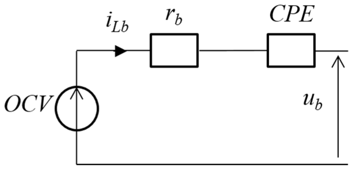
The battery is based on lithium iron phosphate (LFP) technology of the manufacturer A123. The LFP is adapted for high-power application, such as an secondary energy storage system, with a very good thermal stability [28]. The most dominating phenomena of LPF batteries are the ohmic effect and the diffusion process [29]. Hence, the battery model is composed of an open circuit voltage (OCV), a series-resistance rb, and a constant phase element (CPE) impedance (Figure 3). The CPE, defined by
Z C P E = 1 Q ( j ω ) k   k [ 0 , 1 ]
takes into account the voltage drop due to the diffusion process [30]. The battery model parameters have been identified by experimentation for an environmental temperature maintained at 25 °C into a thermal chamber. Each cell develops a nominal capacity of 20 Ah with a nominal voltage of 3.3 V, at 50% of the SoC, for a recommended maximum charge current of 100 A, and a maximum discharge continuous current of 200 A.
The SC bank is modeled to take into account the fast dynamics with a two branch R-C Zubieta and Bonert model [31] (Figure 4). The parameter rsc represents the SC bank series resistance, Csc is its main capacitance, and Ci1 is the coefficient of the variable capacitance evolution with its voltage. All parameters have been identified following the experimental protocols of Zubieta et al [31]. For the majority of the traction applications, this kind of model is enough for energetic study. The SC bank is based on Maxwell BPAK0350-15EA modules (San Diego, CA, USA). Each module develops a maximal voltage of 15 V for a nominal capacity of 58 F.
The smoothing inductors are modeled by R-L series circuits. No saturation of the magnetic circuit is considered:
L i d d t i L i = u i u h i r L i i L i
where rLi and Li are the resistance and the inductance of the inductor, respectively. The index “i” corresponds to each source (“fc” for fuel cell, “sc” for supercapacitors, “b” for battery).
For the DC–DC converters, a response time of the current iLi much greater than the switching frequency of the corresponding converter is considered [32]. In this way, an average model can be used, which is expressed by
{ u d c i = m i u i i d c i = m i η i γ i i L i   m i [ 0 ; 1 ]   , {   γ i = 1 ,   u i i L i < 0   γ i = 1 ,   u i i L i 0
with ηi the converter efficiency and mi its modulation function.
The DC bus model is given by
C b u s d d t u b u s = i b u s = i i t
where Cbus is the DC bus capacitance. The current node between the FC, the battery and the SC branches is furthermore expressed by the Kirchhoff’s laws:
i = i h b + i h s c + i h f c

2.2. Control Organization Using Energetic Macroscopic Representation

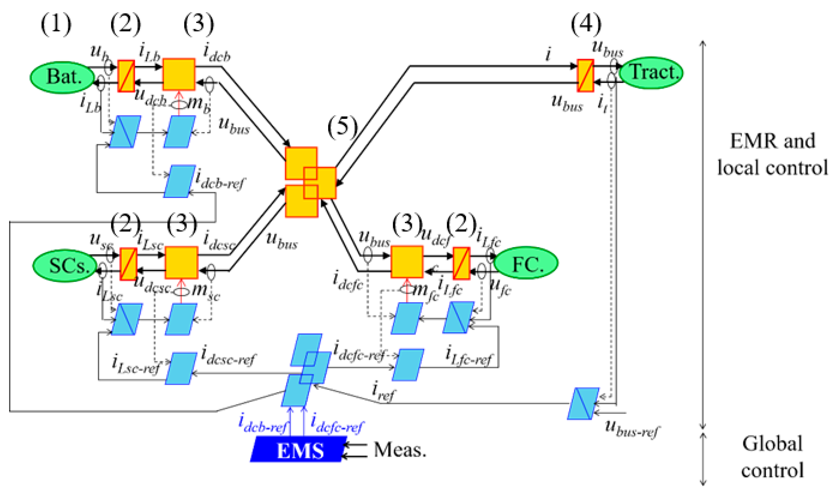
EMR is a graphical formalism used to highlight the energetic properties of the components of a system to develop control schemes [20]. EMR has already been used in several works on the energy management of vehicles [7,33]. The EMR of the studied system is represented in Figure 5 with several pictograms (green and orange pictograms—see Appendix A):
-
Four energy sources (green ovals) depict the three voltage sources (FC, SC, and Bat) and an equivalent current source (representing the electric load of the traction subsystem);
-
One coupling element (orange overlapping square) depicts the current node between the FC, the battery, the SC branches, and the DC bus (5);
-
The smoothing inductors store kinetic energy (2) and are accumulation elements (orange-barred rectangles) with the currents iLX as state variables, i.e., the outputs of the elements. The DC bus is also described as an accumulation element with the voltage ubus as the state variable (4);
-
The DC–DC converters are described by conversion elements (orange square) (3).
EMR is a graphical representation exclusively based on physical integral causality. This property enables a deduction of an inversion-based control scheme that can be implemented directly in real time. This deduction leads to having two control levels: local control and global control. The former is linked to the local control of elements, while the latter is linked to the EMS of the system to coordinate all the elements. The global control gives the control variables (setpoints) that the local control has to track with generally closed-control loops [20].
The local control level, light blue blocks in Figure 5, manages the system components to track the reference of the DC bus voltage to define the suited modulation ratios mfc, mb, and msc of the DC–DC converters. The local control is deduced step-by-step by following the inversion of the EMR of the system. The inversion of accumulation elements (orange-barred rectangular pictograms) is performed using closed-loop controls (light blue crossed parallelograms). Conversion elements (orange square pictograms) are directly inverted with open-loop controls (blue parallelograms). The inversion of coupling elements (orange overlapping pictograms) depicts degrees of freedom that correspond to the output of the EMS. The local control level highlights the fact that four closed-loop controls are required: three controllers to manage the currents of each source (iLfc, iLb, and iLsc) and one controller to track the DC bus voltage (ubus).
The global control level (dark blue block in Figure 5) coordinates the different components to achieve a global objective. The EMS is coded at this level and has to ensure the power sharing between the different energy sources. The outputs of the EMS correspond to the control variables (setpoints) of the local control level. They are highlighted by the EMR-based control organization. In this study, the EMS imposes the output current setpoints of the FC chopper idcfc-ref and battery chopper idcb-ref to minimize the hydrogen consumption and to preserve the battery lifetime, respectively.

3. Real-Time Optimization-Based Strategy

3.1. Optimal Control and Control Organization

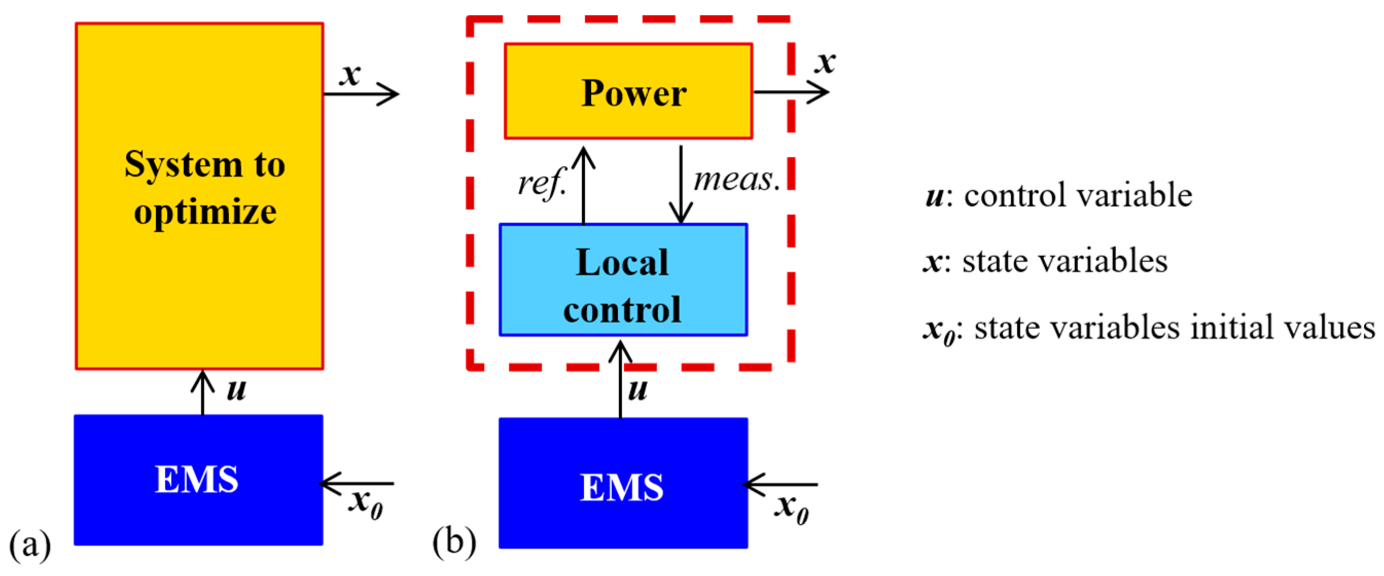
The classical structure of optimal control is depicted in Figure 6a. The optimal control procedure consists to minimize a performance index by setting the control variables u from the EMS to the “system to optimize.” Subsequently, the system to optimize reacts by its state variables x. A single level control is often considered [34]. Based on EMR, this paper proposes to use a multi-level control. Hence, the system to optimize can be seen as the local control level and the power level of the system (Figure 6b). The control variables of the EMS are then the set points of the local control level.

3.2. λ-Control Strategy

The λ-control strategy is a real-time optimization-based EMS, which minimizes a performance index while taking into account some constraints [16,35]. Two steps are necessary to design an optimization-based EMS: (1) the formulation of the optimal control problem with the performance index, the definition of the variables and constraints, and the mathematical description of the problem; and (2) the control problem resolution with the choice of the optimal method (here, the λ-control strategy).
The reference currents calculated by the EMS are set to minimize a performance index. The performance index considered here is to reduce the hydrogen consumption while preserving the battery lifetime. The battery current root mean square (RMS) value is a good indicator of the battery state of stress [36]. The current RMS reduces at the same time the variations of state of change (SoC) and the battery heating, which are the key parameters for battery ageing. The performance index J to be minimized is then expressed by a weighting function,
J = t 0 t f ( Q m + A b i L b 2 ) d t
where Qm is the hydrogen mass flow, Ab is a weighting factor, t0 is the beginning of the driving cycle, and tf is the end of the driving cycle. The higher Ab is, the more the battery current term is taken into account.
In the studied case, the control variables u are the reference currents idcb-ref and idcfc-ref, which are the outputs of the EMS in Figure 5. Some inequality constraints are set to comply with their physical limits. Relationships
0 i d c f c - r e f i d c f c - M
i d c b - m i d c b - r e f i d c b - M
are then used to fix the boundaries with the maximal and minimal currents of the FC and the battery. Moreover, the gradient of the FC current is limited to avoid fuel starvation [37]:
| d d t i d c f c - r e f | ρ i M
where ρi-M is the maximal gradient of the FC current. The state variables x are the stored energies of the secondary energy storage sources: Eb for the battery and Esc for the SC. Constraints are also set on these state variables to respect their physical limits. The stored energy are then constrained with the state of charge SoCb,
S o C b m S o C b ( t ) S o C b M
and the voltage usc,
u s c m u S C ( t ) u s c M
for the battery and the SC, respectively. To compare efficiently the studied FC-BAT-SC-based electric vehicle with a FC-based electric vehicle, without any secondary source, a charge sustaining for the secondary sources is needed. A charge sustaining allows to have a zero energy balance of the secondary sources between the beginning and the end of the driving cycle. Two charge sustaining conditions are then defined for the battery and the SC:
S o C b ( t f ) = S o C b ( t 0 )
u S C ( t f ) = u S C ( t 0 )
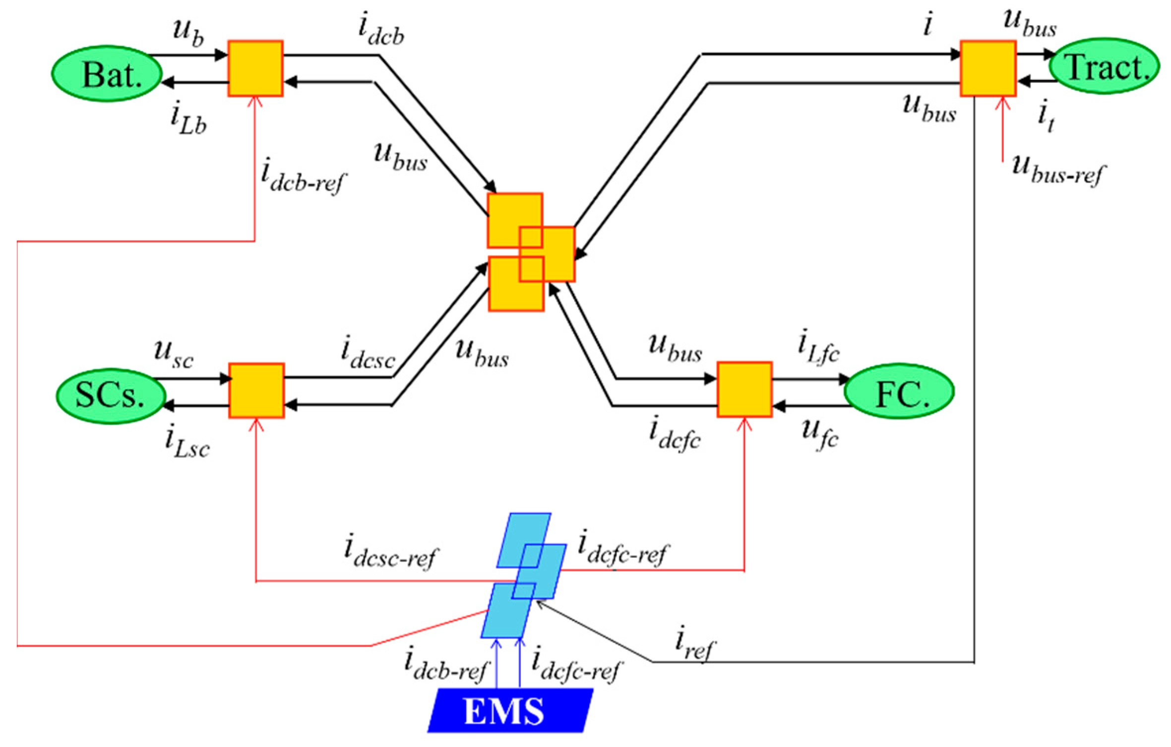
In order to simplify the control problem resolution, namely the second step of the optimization-based EMS design, it is common to use a reduced (quasi-static) model of the system [38]. EMR is based on the action–reaction principle, which enables us to respect the interactions between the different subsystems. This principle allows us to deduce the quasi-static model by neglecting the local control of each element. Moreover, since the reduced model is deduced from a forward description through EMR, the control variables can be implemented in real-time without any change [35].
The DC–DC converters, the smoothing inductors, and their related controls are first reduced. The corresponding equations are given by
i d c X = i d c X - r e f
and   u X i L X = u X i d c X η g X γ g X   with { γ g X = 1 ,   i L X > 0 γ g X = 1 ,   i L X 0
with the assumption that the DC–DC converters are well controlled (14), and the DC bus and its related controller can be reduced as well:
{ u b u s = u b u s - r e f i = i t = i - r e f
According to the dynamical model of the DC bus, no internal losses are considered.
The EMR and the control scheme of the corresponding reduced model are depicted in Figure 7. The accumulation elements (dynamic model) and their corresponding controllers have been replaced by conversion elements (static model).
The mathematical description level consists of defining the performance index with the control variables. The hydrogen mass flow Qm is defined according to the net output power Pfc of the fuel cell by using manufacturer’s data. A second-order interpolation is then achieved to analytically express the performance index:
{ Q m = a P f c 2 + b P f c + c P f c = u b u s i h f c - r e f η g f c
were a, b, and c are the interpolation coefficients. It may be noticed that the performance index J is expressed with idcb-ref and idcfc-ref the control variables:
J = t 0 t f ( a ( u b u s i d c f c - r e f η g f c ) 2 + b u b u s i d c f c - r e f η g f c + c + A b ( u b u s i d c b - r e f η g b γ g b u b ) 2 ) d t
The control problem resolution aims to find the right values of the control variables to comply with the optimal control problem formulation. In this paper, the considered optimal method is the λ-control, which is based on the calculus of variations [39]. This consists in minimizing at each time the Hamiltonian function H defined by
H = a ( u b u s i d c f c - r e f η g f c ) 2 + b u b u s i d c f c - r e f η g f c + c + A b ( u b u s i d c b - r e f η g b γ g b u b ) 2 + λ s c - r e f ( t ) d d t E s c + λ b - r e f ( t ) d d t E b
The control variables expressions can be deduced from
{ H i d c f c - r e f = 0 H i d c b - r e f = 0
if no minimum of H, within the boundaries of the control variables (idcfc-ref and idcb-ref), is assumed. This leads to the expressions
i d c f c - r e f = η g f c 2 η g s c γ g s c λ s c - r e f + η g f c b 2 u b u s a
and   i d c b - r e f = ( η g b γ g b λ b - r e f η g s c γ g s c λ s c - r e f ) u b 2 2 A b η g b 2 γ g b u b u s
The values of a, b, c and ηgX are deduced from look-up tables defined offline.
The key parameters are the Lagrange multipliers λb-ref and λsc-ref. They allow to respect the constraints on the state variables from (10) to (13). However, these parameters are suited for specific driving conditions and can be precisely calculated when the data of the future driving cycle data are known a priori. As a possible solution for real time, the λ-control aims to vary the Lagrange multipliers by using a feedback control to comply with any driving condition [16,40]. In this research, priority is given to the physical limits of the secondary energy storage sources. As a consequence, the Lagrange multipliers λb-ref and λsc-ref are changed from their initial values through a feedback control to comply with the constraints (10) and (11) for every driving condition (Figure 8).

4. Validation of the Real-Time Optimization Based Strategy

4.1. Simulation Results

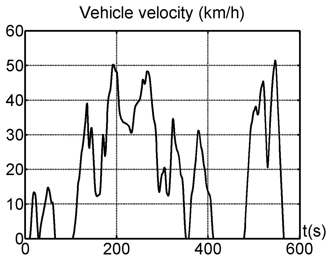
The studied vehicle is a real two-seat electric vehicle, the Tazzari Zero (Imola, Italia) [41], with a mass of 640 kg and an induction machine of 15 kW (Table 1). This kind of vehicle is most of the time used in urban area. The tests have hence been achieved on the low-speed phase (less than 50 km/h) of the standard driving cycle WLTC class 2 (Figure 9) [42]. The battery, SC, and PEM-FC have been designed to comply with energy, power, voltage, mass, and volume. The LFP battery is constituted of 24 A123 cells of 20 Ah connected in series. The SC bank is based on 15 branches connected in parallel. Each branch contains three Maxwell BPAK0350-15EA modules (San Diego, CA, USA) connected in series. The minimal voltage of the SC has been set to 65% to guarantee a high efficiency [43]. Furthermore, the SoC range of the battery has been defined in a narrow range. In literature, it is stated that the Li-ion battery lifetime is improved at high SoC levels. Omer et al., for instance, achieved ageing tests on LFP batteries from 100% SoC to 30% SoC [44]. The best results were obtained for a SoC range between 80% and 100%. In this study, the minimal and maximal SoC have been set to 90% and 100%, respectively.
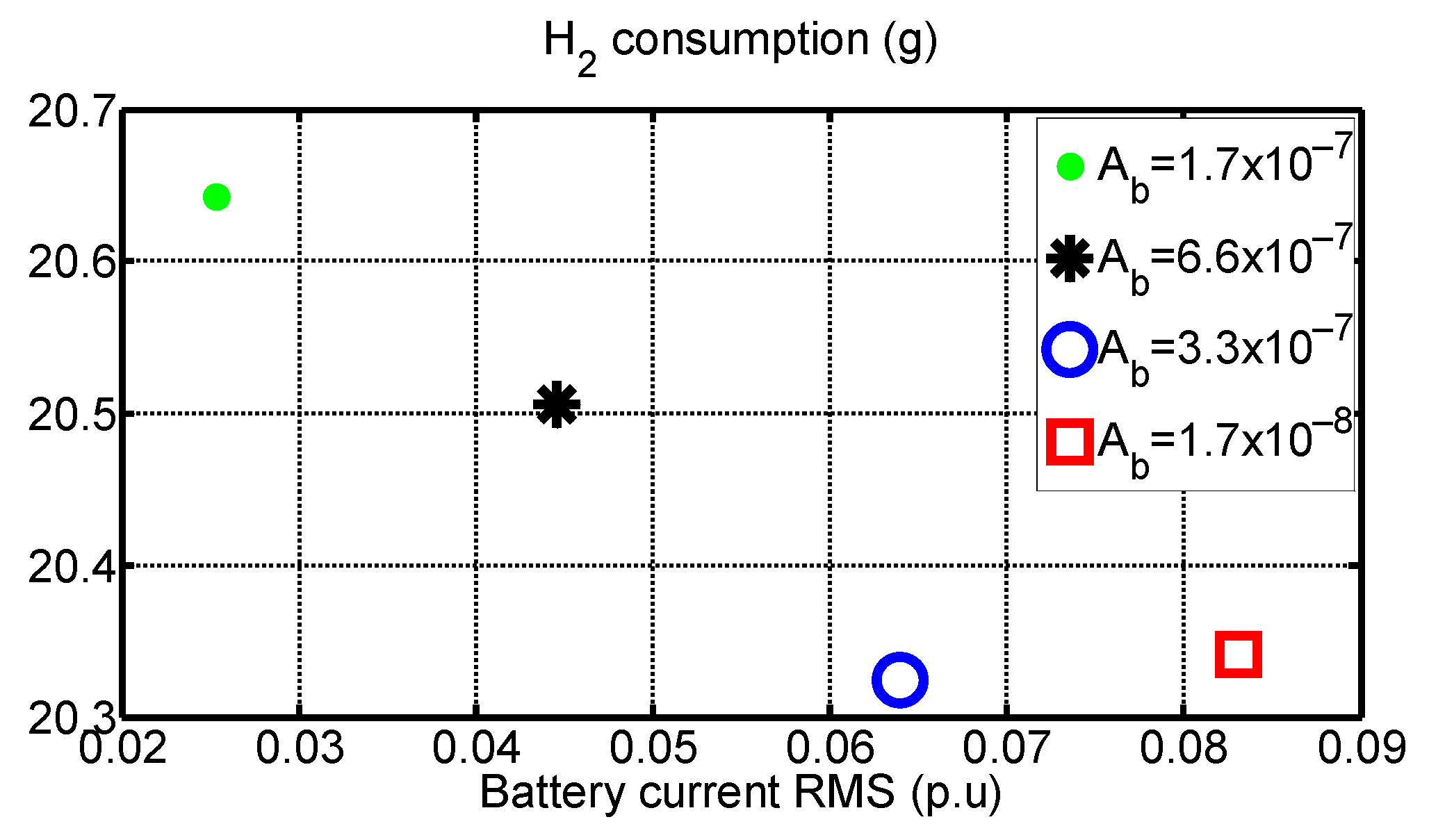
A key issue is the determination of the EMS parameters with the weighting factor Ab and the initial values of the Lagrange multipliers λsc-ref and λb-ref. The initial values of λsc-ref and λb-ref are determined offline by simulation on the standard driving cycle WLTC class 2. They are computed iteratively to comply with the charge sustaining conditions (12) and (13). The weighting factor Ab is determined by a Pareto optimal front [45] in Figure 10, which shows the compromises between both objectives: fuel cell hydrogen consumption and RMS value of the battery current. The value of 3.3 × 10⁻⁷ has been chosen for Ab as compromise to try satisfying both objectives. The initial Lagrange multipliers values are 1.352 × 10⁻⁵ and 1.354 × 10⁻⁵ for λsc-ref and λb-ref, respectively.
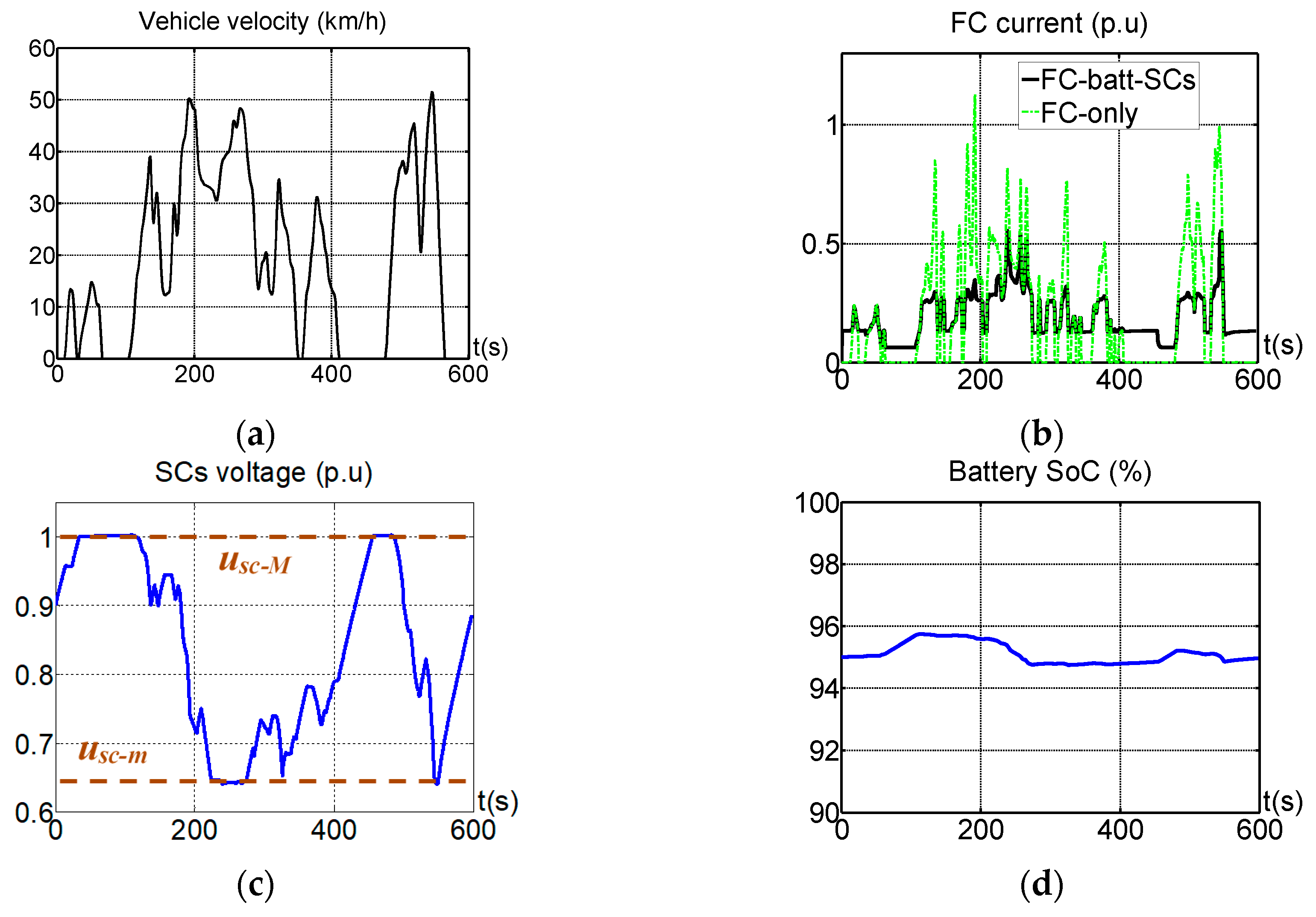
Based on these values, we can see in Figure 11b that the FC current is strongly reduced in comparison with a FC-based electric vehicle without any secondary source (FC-only). The limitations and constraints of the SC (Figure 11c) and battery (Figure 11d) are respected. As expected, the solicitations of the battery are weak. The SC allows the current peaks to be actually absorbed along the driving cycle. In order to quantify the benefit of the SC on the battery lifetime, an FC-BAT-based electric vehicle has also been simulated with the λ-control. The latter contains the same battery as the FC-BAT-SC-based electric vehicle. The performance index is the minimization of the hydrogen consumption. The results are summarized in Figure 12. The SC allows us to drastically reduce the RMS value of the battery current. This reduction is strongly linked with the value of the weighting factor Ab. For the considered value (3.3 × 10⁻⁷), a reduction of 77% can be obtained (Figure 12a). It is clear that any others values of the weighting factor Ab will change the reduction. A value of 6.6 × 10⁻⁷ (star in Figure 10) will reduce for instance the RMS value to 83%. Nevertheless, as the Pareto optimal front shown, the hydrogen consumption will be higher. As far as the performance index is concerned, there is a hydrogen reduction of 7% in comparison with a FC-based electric vehicle (without any secondary source; Figure 12b). To sum up, the simulation results shows that the association of the three sources reduces the hydrogen consumption, while avoiding high dynamics on the FC. Furthermore, the SC allows us to significantly reduce the solicitations of the battery.

4.2. Experimental Validation

Simulation tests have been achieved to assess the strategy performances in driving conditions. This section is devoted to the assessment of the EMS in real-time conditions.
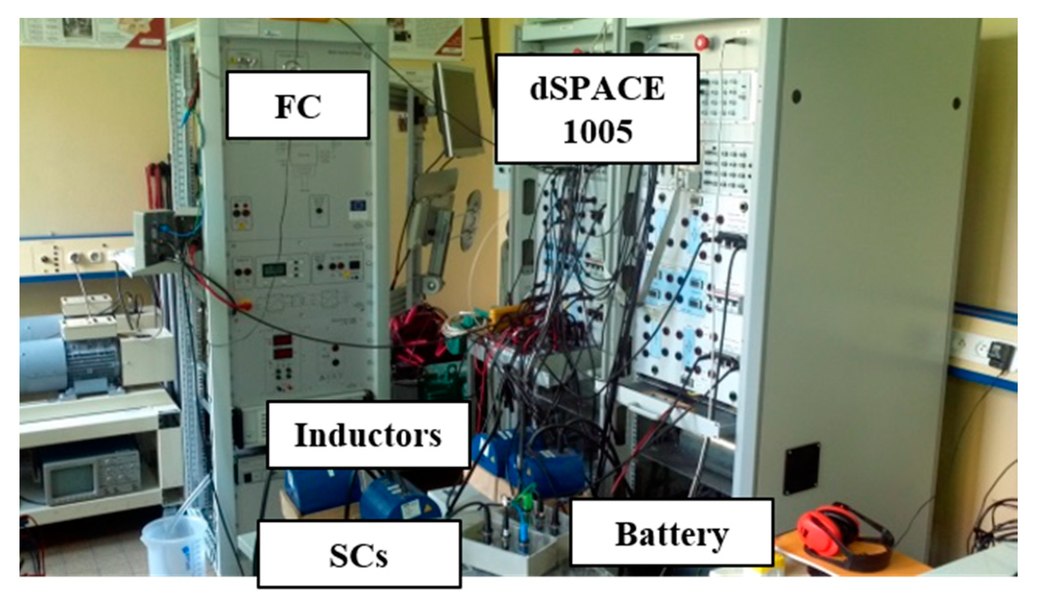
The EMS was implemented in a real system to validate its real-time capabilities. Experimental tests were carried out on the same standard WLTC class 2 driving cycle with the low speed phase. Based on the traction characteristics of the Tazzari Zero, a reduced-scale power hardware-in-the-loop (HIL) simulation is proposed on an experimental platform [46]. It is composed of a 1.2 kW Ballard FC, a bank of Maxwell SC, a DC electric source to emulate the battery, three smoothing inductors, three DC–DC converters, and a controlled current source to emulate the traction subsystem (Figure 13). The controlled current source is chosen as a load drive with a ratio current reduction of 17 compared to the full-scale studied vehicle. Voltages and currents are measured with classical LEM transducers. No additional numerical filters have been added.
The experimental tests were done to assess the EMS under three real-time constraints: implementation, safety and performance.
The λ-control EMS was implemented using a dSPACE 1005 prototyping board (Paderborn, Germany). A 3 GHz dual core processor/3.25 Go RAM memory computer was used. The sampling period was set to 1 ms, and a PWM of 10 kHz was used for the DC–DC converters. The EMS was fully implementable in real time and did not result in any computation issues because the proposed λ-control was developed with elementary operations.
The safety of the system was totally ensured for the experimental tests. In this system, the safety was linked to the maximal limits of the SC voltage and the battery SoC. The EMS enabled us to keep the SC voltage between the desired limits (Figure 14c). The λ-control complied then with the safety requirements. Three SC modules were used in the experimentation; there was hence a ratio of 15 between the simulation tests and the HiL testing. Nevertheless, all experimental tests were achieved with a reduced scale of 1/17th in power. In order to tackle this issue, the minimal SoC of the supercapacitors has to be increased. This corresponds to a SoC of 0.7. Nevertheless, in order to avoid any failure, the maximal voltage has been set to 44 V (0.98 pu), which implies a minimal SoC of 0.68 in Figure 14c.
The EMS performances are confirmed by the experimental tests. As shown by Figure 14a, most of the FC current peaks are avoided. The FC current is then smooth, which is a key point to improve the FC lifetime. Furthermore, as expected, the SC allows the battery state of stress to be reduced (Figure 14b). Some current peaks are then avoided for the battery, which will have a direct impact on its lifetime. Hence, the battery SoC varies in a small range (Figure 14d). It may be noted that, in comparison with simulation results, the charge sustaining (zero energy balance) for both battery and SC are not respected. The Lagrange multipliers have actually been designed to be charge-sustaining, which means that the initial and the final SoC should be equal. This is true for the simulation results. Nevertheless, the parameter discrepancies in real time do not allow us to have exactly an energy balance at the end of the driving cycle.

5. Conclusions

In this paper, a real-time optimization-based energy management strategy by λ-control has been achieved for a fuel cell–battery–supercapacitor-based electric vehicle. A structured method to formulate the optimal control problem and to deduce the model to optimize was first proposed using the energetic macroscopic representation formalism. The performance of the real-time strategy was then assessed by simulation tests for a two-seat urban electric vehicle along a standard driving cycle. The simulation results show that the proposed strategy reduces hydrogen consumption by 7% in comparison with a fuel-cell-based electric vehicle without any secondary source. Moreover, the investigation on the results has confirmed that the SC absorbs the current peaks of the traction, while the battery is used to reduce the dynamics of the fuel cell. To assess the implementation of the strategy in real time, a test rig with a reduced-scale power hardware-in-the-loop (HIL) testing of 1/17th in power has been also developed. The correlation between simulation and experimentation results has proven that the strategy is fully implementable in real time. Moreover, it has been seen that the strategy is safe by avoiding over-charge and discharge (physical limits) of the secondary energy storages sources.
In the future, the robustness of the strategy can be studied under several driving conditions using the same parameters. The temperature effect of the secondary storage energy sources, which can be important, could furthermore be studied on the optimization-based energy management strategy using λ-control.

Author Contributions

Conceptualization, A.C.; Methodology, all authors; Software, A.C.; Validation, A.C.; Formal analysis, A.C.; Writing—original draft preparation, A.C.; Writing—review and editing, all authors; Visualization, A.C. and W.L.; Supervision, A.B., W.L., and R.T. All authors have read and agreed to the published version of the manuscript.

Funding

This research received no external funding.

Conflicts of Interest

The authors declare no conflict of interest.

Appendix A

Table A1. Pictograms of energetic macroscopic representation (EMR).
PictogramElementPictogramElementPictogramElement
Applsci 10 06541 i001source element
(energy source)
Applsci 10 06541 i002accumulation element
(energy storage)
Applsci 10 06541 i003indirect inversion (closed-loop control)
Applsci 10 06541 i004mono-physical conversion element Applsci 10 06541 i005direct inversion (open-loop control)
Applsci 10 06541 i006sensor
mandatory
optional
Applsci 10 06541 i007mono-physical coupling element
(energy distribution)
Applsci 10 06541 i008coupling inversion (energy criteria)

References

  1. Ehsani, M.; Gao, Y.; Emadi, A. Modern Electric, Hybrid Electric, and Fuel Cell Vehicles: Fundamentals, Theory, and Design, Second Edition; CRC Press: Boca Raton, FL, USA, 2009. [Google Scholar]
  2. Sharaf, O.Z.; Orhan, M.F. An overview of fuel cell technology: Fundamentals and applications. Renew. Sustain. Energy Rev. 2014, 32, 810–853. [Google Scholar] [CrossRef]
  3. Tang, Y.; Yuan, W.; Pan, M.; Wan, Z. Experimental investigation on the dynamic performance of a hybrid PEM fuel cell/battery system for lightweight electric vehicle application. Appl. Energy 2011, 88, 68–76. [Google Scholar] [CrossRef]
  4. Ball, M.; Weeda, M. The hydrogen economy—Vision or reality? 1. 1 This paper is also published as Chapter 11 The hydrogen economy—Vision or reality? In Compendium of Hydrogen Energy Volume 4: Hydrogen Use, Safety and the Hydrogen Economy; Ball, M., Basile, A., Veziroglu, T.N., Eds.; Elsevier: Amsterdam, The Netherlands, 2015. [Google Scholar] [CrossRef]
  5. Uddin, K.; Moore, A.D.; Barai, A.; Marco, J. The effects of high frequency current ripple on electric vehicle battery performance. Appl. Energy 2016, 178, 142–154. [Google Scholar] [CrossRef] [Green Version]
  6. Thounthong, P.; Raël, S.; Davat, B. Energy management of fuel cell/battery/supercapacitor hybrid power source for vehicle applications. J. Power Sources 2009, 193, 376–385. [Google Scholar] [CrossRef]
  7. Martinez, J.S.; Hissel, D.; Péra, M.-C.; Amiet, M. Practical Control Structure and Energy Management of a Testbed Hybrid Electric Vehicle. IEEE Trans. Veh. Technol. 2011, 60, 4139–4152. [Google Scholar] [CrossRef]
  8. Li, Q.; Chen, W.; Liu, Z.; Li, M.; Ma, L. Development of energy management system based on a power sharing strategy for a fuel cell-battery-supercapacitor hybrid tramway. J. Power Sources 2015, 279, 267–280. [Google Scholar] [CrossRef]
  9. Wirasingha, S.G.; Emadi, A. Classification and Review of Control Strategies for Plug-In Hybrid Electric Vehicles. IEEE Trans. Veh. Technol. 2011, 60, 111–122. [Google Scholar] [CrossRef]
  10. Yu, Z.; Zinger, D.; Bose, A. An innovative optimal power allocation strategy for fuel cell, battery and supercapacitor hybrid electric vehicle. J. Power Sources 2011, 196, 2351–2359. [Google Scholar] [CrossRef]
  11. García, P.; Torreglosa, J.P.; Fernández, L.M.; Jurado, F. Viability study of a FC-battery-SC tramway con-trolled by equivalent consumption minimization strategy. Int. J. Hydrogen Energy 2012, 37, 9368–9382. [Google Scholar] [CrossRef]
  12. Odeim, F.; Roes, J.; Heinzel, A. Power Management Optimization of a Fuel Cell/Battery/Supercapacitor Hybrid System for Transit Bus Applications. IEEE Trans. Veh. Technol. 2015, 65, 5783–5788. [Google Scholar] [CrossRef]
  13. Jiang, H.; Xu, L.; Li, J.; Hu, Z.; Ouyang, M. Energy management and component sizing for a fuel cell/battery/supercapacitor hybrid powertrain based on two-dimensional optimization algorithms. Energy 2019, 177, 386–396. [Google Scholar] [CrossRef]
  14. Sciarretta, A.; Back, M.; Guzzella, L. Optimal Control of Parallel Hybrid Electric Vehicles. IEEE Trans. Control. Syst. Technol. 2004, 12, 352–363. [Google Scholar] [CrossRef]
  15. Fu, Z.; Li, Z.; Si, P.; Tao, F. A hierarchical energy management strategy for fuel cell/battery/supercapacitor hybrid electric vehicles. Int. J. Hydrogen Energy 2019, 44, 22146–22159. [Google Scholar] [CrossRef]
  16. Kessels, J.T.B.A.; Koot, M.; Bosch, P.V.D.; Kok, D. Online Energy Management for Hybrid Electric Vehicles. IEEE Trans. Veh. Technol. 2008, 57, 3428–3440. [Google Scholar] [CrossRef]
  17. Kermani, S.; Delprat, S.; Guerra, T.M.; Trigui, R.; Jeanneret, B. Predictive energy management for hybrid vehicle. Control. Eng. Pr. 2012, 20, 408–420. [Google Scholar] [CrossRef]
  18. Onori, S.; Tribioli, L. Adaptive Pontryagin’s Minimum Principle supervisory controller design for the plug-in hybrid GM Chevrolet Volt. Appl. Energy 2015, 147, 224–234. [Google Scholar] [CrossRef]
  19. Ettihir, K.; Boulon, L.; Agbossou, K. Optimization-based energy management strategy for a fuel cell/battery hybrid power system. Appl. Energy 2016, 163, 142–153. [Google Scholar] [CrossRef]
  20. Bouscayrol, A.; Hautier, J.-P.; Lemaire-Semail, B. Graphic Formalisms for the Control of Multi-Physical Energetic Systems: COG and EMR. Syst. Des. Methodol. Electr. Energy Syst. 2013, 89–124. [Google Scholar] [CrossRef]
  21. Castaings, A.; Lhomme, W.; Trigui, R.; Bouscayrol, A. Gestion d’énergie par λ-control d’un véhicule multi-sources. In Proceedings of the Symposium de Genie Electrique, Grenoble, France, 7 September 2016. [Google Scholar]
  22. Amjadi, Z.; Williamson, S. Power-Electronics-Based Solutions for Plug-in Hybrid Electric Vehicle Energy Storage and Management Systems. IEEE Trans. Ind. Electron. 2009, 57, 608–616. [Google Scholar] [CrossRef]
  23. Li, Q.; Chen, W.; Li, Y.; Liu, S.; Huang, J. Energy management strategy for fuel cell/battery/ultracapacitor hybrid vehicle based on fuzzy logic. Int. J. Electr. Power Energy Syst. 2012, 43, 514–525. [Google Scholar] [CrossRef]
  24. Zandi, M.; Payman, A.; Davat, B.; Meibody-Tabar, F.; Martin, J.-P.; Pierfederici, S. Energy Management of a Fuel Cell/Supercapacitor/Battery Power Source for Electric Vehicular Applications. IEEE Trans. Veh. Technol. 2010, 60, 433–443. [Google Scholar] [CrossRef]
  25. Manoharan, Y.; Hosseini, S.E.; Butler, B.; Alzhahrani, H.; Senior, B.T.F.; Ashuri, T.; Krohn, J. Hydrogen Fuel Cell Vehicles; Current Status and Future Prospect. Appl. Sci. 2019, 9, 2296. [Google Scholar] [CrossRef] [Green Version]
  26. Boscaino, V.; Rizzo, R.; Miceli, R.; Galluzzo, G.R.; Capponi, G. Comparison of models of fuel cells based on experimental data for the design of power electronics systems. IET Renew. Power Gener. 2015, 9, 660–668. [Google Scholar] [CrossRef]
  27. Corbo, P.; Migliardini, F.; Veneri, O. Hydrogen Fuel Cells for Road Vehicles; Springer Science and Business Media LLC: Berlin, Germany, 2011. [Google Scholar]
  28. Blomgren, G.E. The Development and Future of Lithium Ion Batteries. J. Electrochem. Soc. 2016, 164, A5019–A5025. [Google Scholar] [CrossRef] [Green Version]
  29. Hellwig, C.; Sőrgel, S.; Bessler, W. A Multi-Scale Electrochemical and Thermal Model of a LiFePO4 Battery. ECS Trans. 2019, 35, 215–228. [Google Scholar] [CrossRef] [Green Version]
  30. Montaru, M.; Pelissier, S. Frequency and Temporal Identification of a Li-ion Polymer Battery Model Using Fractional Impedance. Oil Gas. Sci. Technol. Rev. L’Institut Français Pétrole 2009, 65, 67–78. [Google Scholar] [CrossRef]
  31. Zubieta, L.; Bonert, R. Characterization of double-layer capacitors for power electronics applications. IEEE Trans. Ind. Appl. 2000, 36, 199–205. [Google Scholar] [CrossRef] [Green Version]
  32. Delarue, P.; Bouscayrol, A.; Semail, E. Generic control method of multileg voltage-source-converters for fast practical implementation. IEEE Trans. Power Electron. 2003, 18, 517–526. [Google Scholar] [CrossRef]
  33. Horrein, L.; Bouscayrol, A.; Cheng, Y.; Dumand, C.; Colin, G.; Chamaillard, Y. Influence of the heating system on the fuel consumption of a hybrid electric vehicle. Energy Convers. Manag. 2016, 129, 250–261. [Google Scholar] [CrossRef]
  34. Rajabzadeh, M.; Bathaee, S.M.T.; Golkar, M.A. Dynamic modeling and nonlinear control of fuel cell vehicles with different hybrid power sources. Int. J. Hydrogen Energy 2016, 41, 3185–3198. [Google Scholar] [CrossRef]
  35. Castaings, A.; Lhomme, W.; Trigui, R.; Bouscayrol, A. Comparison of energy management strategies of a battery/supercapacitors system for electric vehicle under real-time constraints. Appl. Energy 2016, 163, 190–200. [Google Scholar] [CrossRef]
  36. Vinot, E.; Trigui, R. Optimal energy management of HEVs with hybrid storage system. Energy Convers. Manag. 2013, 76, 437–452. [Google Scholar] [CrossRef] [Green Version]
  37. Thounthong, P.; Davat, B.; Rael, S.; Sethakul, P. Fuel starvation. IEEE Ind. Appl. Mag. 2009, 15, 52–59. [Google Scholar] [CrossRef]
  38. Guzzella, L.; Sciarretta, A. Supervisory Control Algorithms. In Vehicle Propulsion Systems; Springer Science and Business Media LLC: Berlin, Germany, 2013; pp. 243–276. [Google Scholar]
  39. Kirk, D.E. Optimal Control Theory: An Introduction; Dover Publications: Mineola, NY, USA, 2004. [Google Scholar]
  40. Serrao, L.; Sciarretta, A.; Grondin, O.; Chasse, A.; Creff, Y.; Di Domenico, D.; Pognant-Gros, P.; Quérel, C.; Thibault, L. Open Issues in Supervisory Control of Hybrid Electric Vehicles: A Unified Approach Using Optimal Control Methods. Oil Gas. Sci. Technol. Rev. IFP 2013, 68, 23–33. [Google Scholar] [CrossRef] [Green Version]
  41. Dépature, C.; Lhomme, W.; Bouscayrol, A.; Sicard, P.; Boulon, L.; Jokela, T. Characterization of the electric drive of EV: On-road versus off-road method. IET Electr. Syst. Transp. 2017, 7, 215–222. [Google Scholar]
  42. Tutuianu, M.; Marotta, A.; Steven, H.; Ericsson, E.; Haniu, T.; Ichikawa, N.; Ishii, H. Development of a World-Wide Worldwide Harmonized Light Duty Driving Test Cycle (WLTC). UN/ECE/WP.29/GRPE/WLTP IG 2014. Available online: http://www.unece.org/fileadmin/DAM/trans/doc/2014/wp29grpe/GRPE-68-03e.pdf (accessed on 21 June 2020).
  43. Torokhti, A.; Howlett, P. Theory of Multiobjective Optimization; Elsevier: Amsterdam, The Netherlands, 1985. [Google Scholar]
  44. Barrade, P.; Rufer, A. Current capability and power density of supercapacitors: Con-siderations on energy efficiency. In Proceedings of the European Conference on Power Electronics and Applications (EPE) 2003, Toulouse, France, 2–4 September 2003. [Google Scholar]
  45. Omar, N.; Monem, M.A.; Firouz, Y.; Salminen, J.; Smekens, J.; Hegazy, O.; Gaulous, H.; Mulder, G.; Van den Bossche, P.; Coosemans, T.; et al. Lithium iron phosphate based battery—Assessment of the aging parameters and development of cycle life model. Appl. Energy 2014, 113, 1575–1585. [Google Scholar] [CrossRef]
  46. Bouscayrol, A. Hardware-in-the-Loop Simulation. In The Handbook of Optical Communication Networks; Informa UK Limited: Colchester, UK, 2011; pp. 1–15. [Google Scholar]
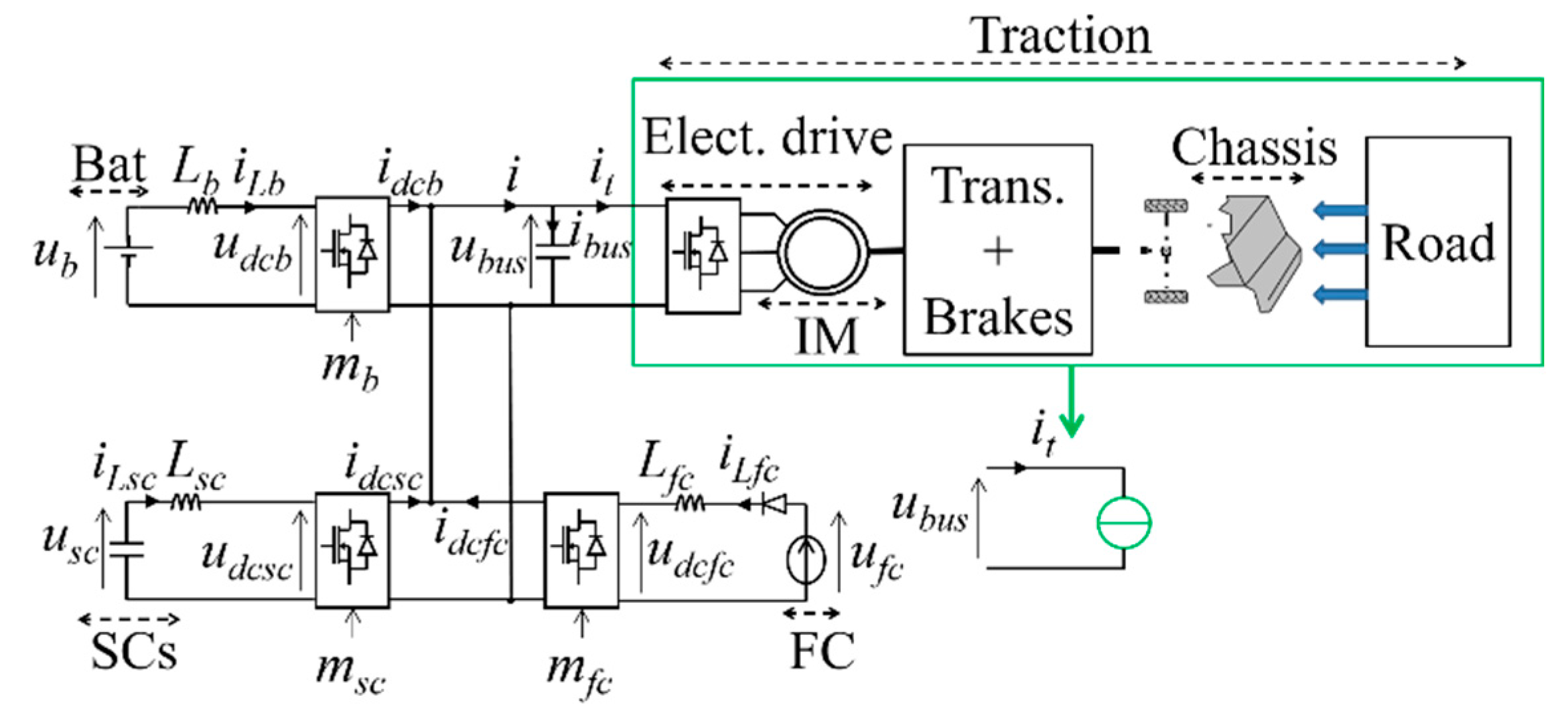
Figure 1. System architecture.
Applsci 10 06541 g001
Figure 2. Polarization curve of the fuel cell.
Applsci 10 06541 g002
Figure 3. Battery model.
Applsci 10 06541 g003
Figure 4. Supercapacitor model.
Applsci 10 06541 g004
Figure 5. Energetic macroscopic representation and control organization of the system.
Applsci 10 06541 g005
Figure 6. Optimal control scheme: (a) single-level control, (b) multi-level control.
Applsci 10 06541 g006
Figure 7. Energetic macroscopic representation and control scheme of the reduced model.
Applsci 10 06541 g007
Figure 8. λ-control strategy scheme.
Applsci 10 06541 g008
Figure 9. Standard driving cycle worldwide harmonized light-duty vehicles test cycle (WLTC) class 2 low-speed phase.
Applsci 10 06541 g009
Figure 10. Corresponding Pareto optimal front to define the weighting factor Ab.
Applsci 10 06541 g010
Figure 11. (a) WLTC class 2 low-speed phase. (b) Fuel cell currents iLfc for the fuel cell–battery–super capacitor (FC-BAT-SC)-based vehicle (black line) and fuel cell (FC)-based vehicle without any secondary source (green line). (c) Voltage of the super capacitors usc. (d) State of charge of the battery SoCb.
Applsci 10 06541 g011
Figure 12. Performance index: (a) H2 consumptions of the FC-BAT-based vehicle (green color) and FC-BAT-SC-based vehicle (black color); (b) battery current (root mean square (RMS) value) of the FC-based vehicle without any secondary source (green color) and FC-BAT-SC-based vehicle (black color).
Applsci 10 06541 g012
Figure 13. Experimental test rig.
Applsci 10 06541 g013
Figure 14. Experimental results: (a) DC–DC current of the fuel cell idcfc (red line) and traction current it (black line); (b) currents of the supercapacitors iLsc (green line) and battery iLb (blue line); (c) voltage of the supercapacitors usc; (d) state of charge of the battery SoCb.
Applsci 10 06541 g014aApplsci 10 06541 g014b
Table 1. System parameters.
Fuel Cell StackType: PEMFC
Maximal Power: 20 kW
Voltage Range: 50–80 V
Vehicle640 kg
Electric driveRated power: 15 kW
Supercapacitor bankusc-M = 45 V
Csc = 290 F | rsc = 3.8 mΩ
usc-m = 0.65 usc-M
uSC-0 = 0.9 usc-M
Battery24 LFP cells (3.3 V/20 Ah)
SoCb-M = 100%
SoCb-m = 90%
SoCb-0 = 95%