Abstract
The importance of a reliable blade root connection has grown due to the higher-gravity-induced edgewise loads on the blade root that resulted from the recent increased size and weight of a wind turbine rotor blade. To avoid the loosening of a bolt joint connection or even consecutive blade failures, the stress concentration factor (SCF) at the bolt thread root that is sensitive to fatigue should be understood comprehensively. In this work, two-dimensional and three-dimensional finite element (FE) analysis methods were used to determine the SCF at the bolt threads both between an insert and a M42 bolt used for a large offshore blade, and between a M42 bolt and a nut. The effect of various geometric parameters on the SCF were also investigated, which included shank diameter, nut height, nut type, and relief cone. Results showed that the decreased diameter of a M42 bolt shank diameter was the dominant design driver in reducing the stress concentration factor by 40%, from 3.94 to 2.32. The round nut type was also a recommended factor to be implemented to connect bolts and inner pitch bearing with an additional 10% SCF reduction. The relief cones applied to bolt threads and insert threads also contributed to the reduction of SCF to 2.01, a 49% reduction in total. This work not only provides guidelines by which to choose the proper geometry of the bolt and nut for a large blade, but also could be beneficial in designing bolted joint connections of segment or modular blades.
1. Introduction
Wind turbine generators (WTGs) have gained much attention because they utilize one of the cleanest and most environmentally friendly energy resources as an alternative to fossil fuels [1]. A modern wind turbine typically consists of blades, a nacelle including a generator and gearbox, and a substructure such as a tower. The two or three blades are coupled to the rotatable hub through a pitch bearing system by the blade root joint connection [2].
Currently, two types of root joint connections are widely used in commercial wind turbine blades: steel insert type and T-bolt (also referred to as “IKEA” connection) type, as shown in Figure 1 [3,4]. Traditionally, T-bolts or IKEA connections have been a popular choice for connecting a blade to the hub of the wind turbine due to the relatively easy manufacturing process and convenience of replacement. T-bolt joints have cross-bolts positioned perpendicular to the root cylinder surface, and longitudinal bolts connect the hub to the cross-bolt [5]. Martinez investigated the T-bolt joint both numerically and with experiments and concluded that the T-bolt joint is reliable and inexpensive [6]. As blade length has increased, however, a couple of issues have come up such as a transportation difficulty and excessive material usage due to the increased blade circle diameter (BCD) and increased root layer thickness to ensure structural durability [7,8].
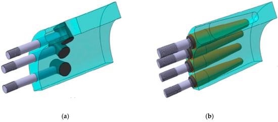
Figure 1.
Blade root connection types: (a) T-bolt type and (b) insert type [3].
During the last decade, the insert joint technology has been applied, especially to large offshore blades, which could reduce the BCD and weight as an alternative to T-bolted connections [9]. The advantage of the insert joint is that compared to the conventional T-bolt connection about 35% more bolts can be implemented. Further, no damage is caused by drilling, and another potential advantage is that inserts can be included as prefabricated parts in a root infusion [10].
As blade size becomes larger, a fatigue failure in the root region becomes an increasing problem due to the higher-gravity-induced edgewise loads [11,12]. That is, as the effect of the higher edgewise fatigue loading on the blade root region becomes critical, the stress concentration factor (SCF) at the bolt thread root that is sensitive to fatigue also becomes an important parameter in addition to the structural integrity of root laminate [13,14,15]. Many experiments were performed to ensure the quality of laminated root insert joint, for example, the bonding failure mechanism and manufacturing quality experimentally and numerically [16]. Zheng et al. recently performed a failure analysis of a fractured high-strength bolt used in a MW Class wind turbine blade connection system, and concluded that the bolt failure was caused by insufficient tightening and improper manufacturing procedure [17]. There is, however, little work on the stress concentration factor of a bolt–nut joint and a bolt–insert joint connection that depends on the varying geometric parameters of bolts, nut, and insert. Therefore, the comprehensive understanding of SCFs at the thread interface both between the insert and bolt and between the bolt and nut are important to avoid unwanted structural failure, especially for a large blade with M42 bolts.
In this work, the stress concentration factors on bolted joint connections will be fully investigated with two-dimensional and three-dimensional linear finite element models with contact elements according to the changes of the geometric parameters, including shank diameter, nut height, nut type, and relief cone angle. Based on close investigation, guidelines for choosing the proper connection type for an offshore wind blade root connection will be provided. This work will be also beneficial for designing bolted joint connections of segment or modular blades [18,19].
2. Numerical Analysis Model
This section describes the specification of a blade root connection model consisting of a steel insert, bolt, and nut. Finite element models, including contact elements and boundary conditions, will also be described.
2.1. Blade Root Connection Model
The specifications of the current blade root connection model with an insert are listed in Table 1, and the overall component diagram, consisting of a blade root connection such as a blade root, a flange, a pitch bearing, a hub, etc., is shown in Figure 2.

Table 1.
Root joint model description of a large wind turbine rotor blade.
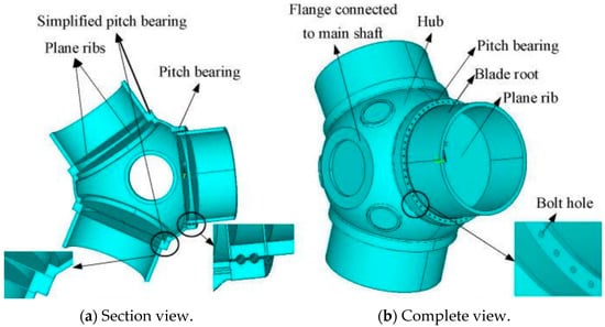
Figure 2.
Overall component diagram consisting of a blade root connection [17].
Figure 3 and Figure 4 show the design parameters of bolt and nut geometry used for the current analysis. In the next section, the close investigation of the effect of parameters on the SCF at the bolted joint model will be performed through a finite element analysis:
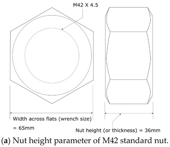
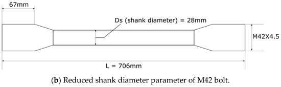
Figure 3.
Geometry of nut and bolt.
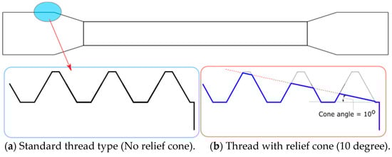
Figure 4.
Schematic diagram of a relief cone parameter at the bolt thread.
- Nut type effect on SCF;
- Nut height (or number of thread engagements) effect on SCF;
- Reduced shank diameter effect on SCF;
- Relief cone effect on SCF.
2.2. Finite Element Model
The symmetric part of a root connection model including a blade root, a pitch bearing, and a piece of hub is shown in Figure 5a,b, and the internal detail model of the bolt–insert joint and the bolt–nut joint can be seen in Figure 5c,d. The six components of loads are applied to the blade root joint in the direction of the blade root coordinate system, as shown in Figure 6.
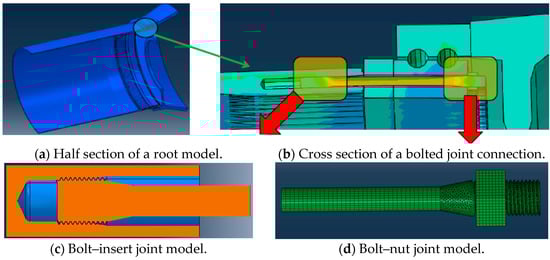
Figure 5.
Schematic diagram of a blade root joint model.
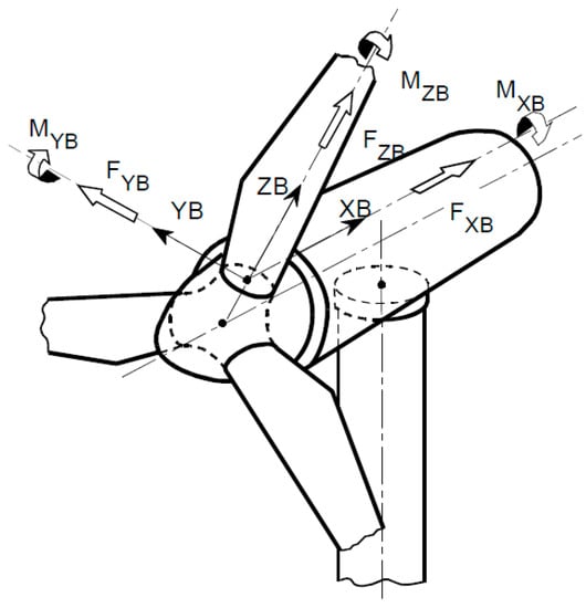
Figure 6.
Blade coordinate system; XB in direction of the rotor axis, ZB in radial direction along the blade, and YB in direction of the cross product of ZB and XB [4].
The finite element model consists of two types of elements in ABAQUS. The C3D8 element, used for bolt shank and nut geometries, is a general purpose linear brick element, fully integrated (2 × 2 × 2 integration points), which uses linear interpolation in each direction and is often called first-order element, and every node has three degrees of freedom: translation in the nodal X, Y, and Z direction. The C3D10 element, used for threads and transition areas, is also a general-purpose tetrahedral element with four integration points [20].
Surface-to-surface contact formulation from the general contact option in ABAQUS/standard was used. The contact pairs, master surface (nut or insert thread surface), and slave surface (bolt surface) were defined with the tangential frictional coefficient of 0.1, which is a general value used for contact analysis between untreated steels and hard contact default in the normal direction to allow for the shear force and open/closed change during contact analysis according to the surface definition in ABAQUS manual. The seed size of 2.0 was used to minimize the incorrect contact behavior due to the very coarse meshes, that is, the gross penetration of the master surface into the slave surface. For the current analysis in ABAQUS/standard, the following SI unit system is used; mm for length, Newton for load, MPa (N/mm2) for stress, and kilogram for weight.
For detailed investigation of SCF at the engagement threads, the FE model was focused on the bolt–nut joint and bolt–insert joint model with the preload of 400 kN applied at the bolt tip and the fixed condition of insert and nut as shown in Figure 7. Material properties of bolt and nut are listed in Table 2, and measured values of M42 bolts are listed in Table 3.
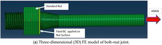
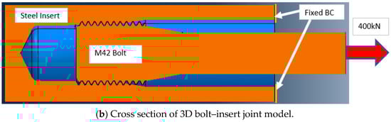
Figure 7.
Boundary condition of bolted joint model.
Table 2.
Material properties of insert, bolt, and nut.
Table 3.
Measured material properties of M42 bolt.
3. Numerical Analysis Results
Before closing the investigation on stress concentration factors, the convergence of 3D finite element analysis depending on the mesh size was checked. The coarse mesh model with seed size of 2.0 mm showed just 0.537% deviation compared to the fine mesh model with seed size of 0.2 mm, and stress concentration factors were highest in the first engaged thread and decreased in each successive thread moving toward the end of the bolt as listed in Table 4. Due to the time-consuming and costly nature of computation, a seed size of 0.2 mm was used for the thread and transition zone and a size of 2.0 mm was used for the body of the bolt and nut as shown in Figure 8. CA4X elements were used for the two-dimensional (2D) FE model, and C4D8 elements were used for the 3D FE model.
Table 4.
Mesh size effect on the stress concentration factor (SCF).
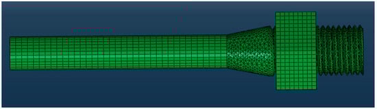
Figure 8.
Mesh size distribution (2.0 mm for the body of bolt and nut, 0.2 mm for the thread/transition zone).
In this section, various bolted joint conditions with geometric design modifications were numerically analyzed to determine the extent to which they reduce stress concentrations. The design modifications included nut type (standard vs. round), nut height (number of engaged threads), shank diameter, and relief cone angle.
3.1. Nut Type Effect on SCF
Two different nut types—standard and round—were studied for the reduction of the SCF, as shown in Figure 9. For the blade root joint analysis, smeared material properties for blade root laminates and steel properties for bolt and nut components were used. For the reliable and intensive analysis of a bolted joint, 2D model and 3D model were constructed as shown in Figure 10, and results from both the three-dimensional linear FE analysis and the two-dimensional liner FE analysis are shown in Table 5 and Table 6.
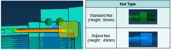
Figure 9.
Nut type (standard nut and round nut).
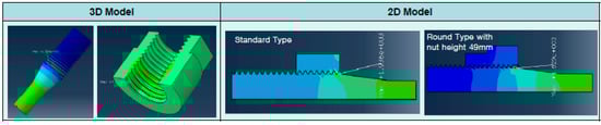
Figure 10.
Finite element model (two-dimensional (2D) and 3D model).
Table 5.
Analysis results from 3D finite element (FE) model.
Table 6.
Analysis results from 2D FE model.
The values of stresses and SCFs resulting from 3D and 2D FE models are reasonably similar. The values show that using the round nut type to connect bolts and inner pitch bearing will reduce SCF by 18.5% on average compared to the standard nut type. The effect of the number of engaged threads (or nut height) on SCF will be explained in the following section.
3.2. Nut Height (Number of Engaged Threads) Effect on SCF
Three round type nuts with three different nut heights (49 mm, 44.5 mm, and 40 mm) and number of engaged threads (9, 8, and 7) were examined through 2D FE analysis to determine if the design parameter is a meaningful factor in reducing SCFs as shown in Figure 11.
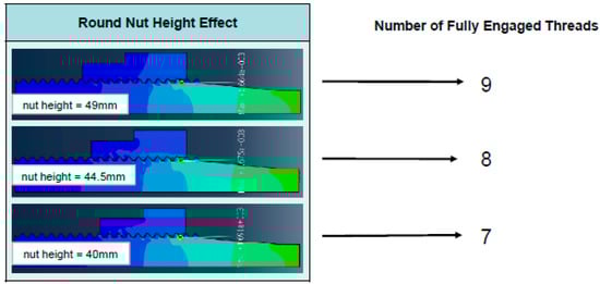
Figure 11.
Nut height and number of engaged threads of M42 round nut.
Table 7 indicates that nut height or number of engaged threads is not a critical factor in reducing SCF.
Table 7.
SCFs based on change of nut height.
3.3. Reduced Shank Diameter Effect on SCF
The straight bolt with 37.1 mm nominal diameter and neck-down bolt with reduced shank diameter of 28 mm were analyzed with two different nut types—standard and round nut type—as shown in Figure 12.
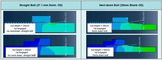
Figure 12.
2D stress analysis of straight bolt and neck-down (reduced shank) bolt.
Irrespective of nut types, the SCF of bolt with reduced shank diameter was reduced dominantly by 45% as listed in Table 8 and Table 9.
Table 8.
Bolt shank effect on SCF (connected with standard nut type).
Table 9.
Bolt shank effect on SCF (connected with round nut type).
3.4. Relief Cone Effect on SCF
In this section, the effect of the relief cone angle (10 degree) on SCFs was investigated at the bolt–insert joint model, and the combined effect of the cone angle and reduced shank diameter was also examined, as shown in Figure 13. The various analysis cases with the combination of shank diameter and cone angle are shown in Figure 14 and Figure 15 with two-dimensional and three-dimensional models, respectively.
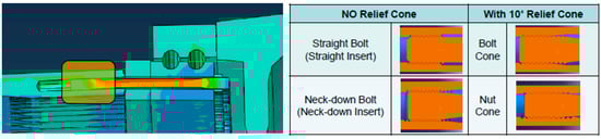
Figure 13.
Model comparison (straight or neck-down bolt with/without a relief cone model).
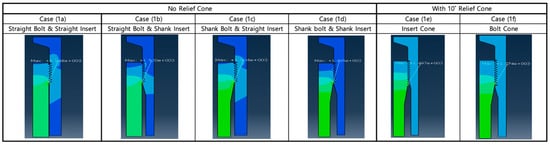
Figure 14.
2D bolt joint models with varying parameters (straight/shank and with/without a relief cone).
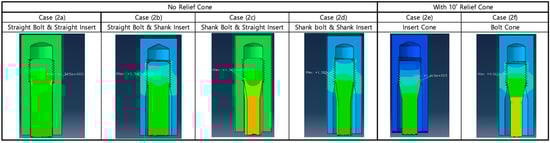
Figure 15.
3D Bolt joint models with varying parameters (straight/shank and with/without a relief cone).
As listed in Table 10 and Table 11, the SCF was further reduced by 10% with the application of the relief cone angle. In particular, applying the relief cone angle to the bolt was more beneficial in reducing SCF than insert cone application by 10% at most. Therefore, the bolted joint model consisting of a neck-down bolt (reduced shank bolt) with a relief cone and a root insert with a large shank diameter showed the largest reduction in the SCF by 50% in total.
Table 10.
SCF with varying parameters (straight/shank and with/without a relief cone).
Table 11.
SCF with varying parameters (straight/shank and with/without a relief cone).
4. Discussion
As the size of a wind turbine rotor blade is increases, the SCF at the bolt threads sensitive to fatigue becomes a more important parameter for the bolted joint connection to endure the designed fatigue life and to avoid the loosening of a bolt joint connection or even consecutive blade failure. In this work, the SCFs at the bolt threads of the bolted joint connection such as bolt–insert joint and bolt–nut joint were thoroughly computed by two-dimensional and three-dimensional linear finite element analysis methods with contact elements in detail, and the effect of various design parameters on the SCF were investigated as well. From this work, it is shown that a round nut is better than a standard nut at reducing stress concentration factor by 18.5% on average. Two-dimensional and three-dimensional FE analysis resulted in remarkably close SCFs, from 3.04 to 2.41 and from 2.98 to 2.51, respectively, from standard nut type to round nut type. However, the different nut heights of 40 mm, 44.5 mm, and 49 mm, or different number of engaged threads of 7, 8, and 9, showed little effect on SCFs. That is, the nut height or the number of the engaged threads was not a critical parameter in reducing the SCFs. Among other design parameters, the reduced shank diameter of the neck-down bolt was a dominant player in reducing SCF by 41% irrespective of nut type. In addition to the reduced shank diameter effect, the SCF was reduced further by 13% from 2.32 to 2.01 with the application of the relief cone angle at the bolt threads. Therefore, it was recommended to use the bolted joint model consisting of a neck-down bolt (reduced shank bolt) with a relief cone and a root insert with a large shank diameter to reduce the SCF by 50%, and it is also recommended to use the round nut type for additional reduction. Besides, based on the excellent agreement between two-dimensional and three-dimensional finite element analysis results, 2D finite element analysis is preferred due to the easy FE modeling, high-quality mesh construction, and high computational efficiency. During the current work, the pretension load was only considered for the comprehensive investigation of SCF at the bolt threads. Therefore, for further reliable and fatigue-safe bolted connection at the blade root joint, multiple loading conditions and fatigue analysis methodologies need to be considered in the future.
Funding
This work was supported by Brain Pool Program through the National Research Foundation of Korea (NRF) funded by the Ministry of Science and ICT (grant number: 2019H1D3A2A02102093).
Acknowledgments
I acknowledge the administrative and technical support of the Offshore Floating Wind Energy System Engineering Department of University of Ulsan.
Conflicts of Interest
The author declares no conflict of interest.
References
- Future of Wind: Deployment, Investment, Technology, Grid Integration, Socio-Economic Aspects; IRENA: Abu Dahbi, UAE, 2019; ISBN 978-92-9260-155-3.
- Manwell, J.; McGowan, J.; Rogers, A.L. Wind Energy Explained; Wiley: Hoboken, NJ, USA, 2002. [Google Scholar]
- Briggs, A.A.; Zhang, Z.; Dhakal, H. Study on T-bolt and pin-loaded bearing strengths and damage accumulation in E-glass/epoxy blade applications. J. Compos. Mater. 2014, 49, 1047–1056. [Google Scholar] [CrossRef]
- DNV GL AS. Rotor Blades for Wind Turbines. In Standard; DNVGL-ST-0376—Edition December 2015; DNVGL: Oslo, Norway, 2015. [Google Scholar]
- Scherer, R.; Martinez, V.; Mayugo, J.A.; Costa, J. Design and Performance of the T-Bolt Connection of Rotor Blades. In Proceedings of the European Wind Energy Conference, Nice, France, 1–5 March 1999. [Google Scholar]
- Martínez-Moll, V.; Güemes, A.; Trias, D.; Blanco, N.; Trias, D. Numerical and experimental analysis of stresses and failure in T-bolt joints. Compos. Struct. 2011, 93, 2636–2645. [Google Scholar] [CrossRef]
- Griffin, D.A.; Ashwill, T.D. Blade System Design Studies Volume I: Composite Technologies for Large Wind Turbine Blades; Sandia National Laboratories: Albuquerque, NM, USA, 2002. [Google Scholar]
- Nolet, S. Plenary 5: Large Turbines on Land—A Blade Maker’s View. In Proceedings of the Nawea/Windtech 2019, Amherst, MA, USA, 14–16 October 2019. [Google Scholar]
- DNV/Riso. Guidelines for Design of Wind Turbine, 2nd ed.; Chapter 5. Rotor; DNVGL: Oslo, Norway, 2002. [Google Scholar]
- Caruso, C.D.; General Electric Company. Rotor Blade Assembly Having a Stiffening Root Insert. U.S. Patent US 9464622B2, 11 October 2016. [Google Scholar]
- Ashuri, T. Beyond Classical Upscaling: Integrated Aeroservoelastic Design and Optimization of Large Offshore Wind Turbines; Wohrman: Zutphen, The Netherlands, 2012. [Google Scholar]
- Jensen, F.M.; Kling, A.; Sørensen, J.D. Change in Failure Type when Wind Turbine Blades Scale-Up Sandia Wind Turbine Workshop. In Proceedings of the European Wind Energy Conference and Exhibition 2012, Copenhagen, Denmark, 16–19 April 2012. [Google Scholar]
- Chalupnik, J.D. Stress concentrations in bolt-thread roots. Exp. Mech. 1968, 8, 398–404. [Google Scholar] [CrossRef][Green Version]
- Fukuoka, T.; Yamasaki, N.; Kitagawa, H.; Hamada, M. Stress concentration at the root of a screw thread (Effects of root radius and friction coefficient). Trans. Jpn. Soc. Mech. Eng. Ser. A 1986, 52, 2201–2208. [Google Scholar] [CrossRef]
- Fukuoka, T. Evaluation of the Method for Lowering Stress Concentration at the Thread Root of Bolted Joints With Modifications of Nut Shape. J. Press. Vessel Technol. 1997, 119, 1–9. [Google Scholar] [CrossRef]
- Martínez, V.; Güemes, A.; Blanco, N.; Costa, J. Three-Dimensional Stress Analysis of the T-Bolt Joint. In Proceedings of the 13th International Congress on Composite Materials, Beijing, China, 25–29 June 2001. [Google Scholar]
- Chen, G.; Wen, J. Load Performance of Large-Scale Rolling Bearings with Supporting Structure in Wind Turbines. J. Tribol. 2012, 134, 041105. [Google Scholar] [CrossRef]
- Peeters, M.; Santo, G.; DeGroote, J.; Van Paepegem, W. The Concept of Segmented Wind Turbine Blades: A Review. Energies 2017, 10, 1112. [Google Scholar] [CrossRef]
- Ha, K.; Bätge, M.; Melcher, D.; Czichon, S. Development and feasibility study of segment blade test methodology. Wind Energy Sci. 2020, 5, 591–599. [Google Scholar] [CrossRef]
- Smith, M. ABAQUS/Standard User’s Manual, Version 6.14; Dassault Systèmes Simulia Corp; Dassault Systems: Livonia, MI, USA, 2011. [Google Scholar]


© 2020 by the author. Licensee MDPI, Basel, Switzerland. This article is an open access article distributed under the terms and conditions of the Creative Commons Attribution (CC BY) license (http://creativecommons.org/licenses/by/4.0/).